WO2013186924A1 - ハイブリッド車両用駆動装置 - Google Patents
ハイブリッド車両用駆動装置 Download PDFInfo
- Publication number
- WO2013186924A1 WO2013186924A1 PCT/JP2012/065393 JP2012065393W WO2013186924A1 WO 2013186924 A1 WO2013186924 A1 WO 2013186924A1 JP 2012065393 W JP2012065393 W JP 2012065393W WO 2013186924 A1 WO2013186924 A1 WO 2013186924A1
- Authority
- WO
- WIPO (PCT)
- Prior art keywords
- engine
- rotating machine
- speed
- planetary gear
- ecu
- Prior art date
Links
Images


Classifications
-
- B—PERFORMING OPERATIONS; TRANSPORTING
- B60—VEHICLES IN GENERAL
- B60W—CONJOINT CONTROL OF VEHICLE SUB-UNITS OF DIFFERENT TYPE OR DIFFERENT FUNCTION; CONTROL SYSTEMS SPECIALLY ADAPTED FOR HYBRID VEHICLES; ROAD VEHICLE DRIVE CONTROL SYSTEMS FOR PURPOSES NOT RELATED TO THE CONTROL OF A PARTICULAR SUB-UNIT
- B60W20/00—Control systems specially adapted for hybrid vehicles
- B60W20/10—Controlling the power contribution of each of the prime movers to meet required power demand
-
- B—PERFORMING OPERATIONS; TRANSPORTING
- B60—VEHICLES IN GENERAL
- B60K—ARRANGEMENT OR MOUNTING OF PROPULSION UNITS OR OF TRANSMISSIONS IN VEHICLES; ARRANGEMENT OR MOUNTING OF PLURAL DIVERSE PRIME-MOVERS IN VEHICLES; AUXILIARY DRIVES FOR VEHICLES; INSTRUMENTATION OR DASHBOARDS FOR VEHICLES; ARRANGEMENTS IN CONNECTION WITH COOLING, AIR INTAKE, GAS EXHAUST OR FUEL SUPPLY OF PROPULSION UNITS IN VEHICLES
- B60K6/00—Arrangement or mounting of plural diverse prime-movers for mutual or common propulsion, e.g. hybrid propulsion systems comprising electric motors and internal combustion engines ; Control systems therefor, i.e. systems controlling two or more prime movers, or controlling one of these prime movers and any of the transmission, drive or drive units Informative references: mechanical gearings with secondary electric drive F16H3/72; arrangements for handling mechanical energy structurally associated with the dynamo-electric machine H02K7/00; machines comprising structurally interrelated motor and generator parts H02K51/00; dynamo-electric machines not otherwise provided for in H02K see H02K99/00
- B60K6/20—Arrangement or mounting of plural diverse prime-movers for mutual or common propulsion, e.g. hybrid propulsion systems comprising electric motors and internal combustion engines ; Control systems therefor, i.e. systems controlling two or more prime movers, or controlling one of these prime movers and any of the transmission, drive or drive units Informative references: mechanical gearings with secondary electric drive F16H3/72; arrangements for handling mechanical energy structurally associated with the dynamo-electric machine H02K7/00; machines comprising structurally interrelated motor and generator parts H02K51/00; dynamo-electric machines not otherwise provided for in H02K see H02K99/00 the prime-movers consisting of electric motors and internal combustion engines, e.g. HEVs
- B60K6/42—Arrangement or mounting of plural diverse prime-movers for mutual or common propulsion, e.g. hybrid propulsion systems comprising electric motors and internal combustion engines ; Control systems therefor, i.e. systems controlling two or more prime movers, or controlling one of these prime movers and any of the transmission, drive or drive units Informative references: mechanical gearings with secondary electric drive F16H3/72; arrangements for handling mechanical energy structurally associated with the dynamo-electric machine H02K7/00; machines comprising structurally interrelated motor and generator parts H02K51/00; dynamo-electric machines not otherwise provided for in H02K see H02K99/00 the prime-movers consisting of electric motors and internal combustion engines, e.g. HEVs characterised by the architecture of the hybrid electric vehicle
- B60K6/44—Series-parallel type
- B60K6/445—Differential gearing distribution type
-
- B—PERFORMING OPERATIONS; TRANSPORTING
- B60—VEHICLES IN GENERAL
- B60W—CONJOINT CONTROL OF VEHICLE SUB-UNITS OF DIFFERENT TYPE OR DIFFERENT FUNCTION; CONTROL SYSTEMS SPECIALLY ADAPTED FOR HYBRID VEHICLES; ROAD VEHICLE DRIVE CONTROL SYSTEMS FOR PURPOSES NOT RELATED TO THE CONTROL OF A PARTICULAR SUB-UNIT
- B60W10/00—Conjoint control of vehicle sub-units of different type or different function
- B60W10/04—Conjoint control of vehicle sub-units of different type or different function including control of propulsion units
- B60W10/06—Conjoint control of vehicle sub-units of different type or different function including control of propulsion units including control of combustion engines
-
- B—PERFORMING OPERATIONS; TRANSPORTING
- B60—VEHICLES IN GENERAL
- B60W—CONJOINT CONTROL OF VEHICLE SUB-UNITS OF DIFFERENT TYPE OR DIFFERENT FUNCTION; CONTROL SYSTEMS SPECIALLY ADAPTED FOR HYBRID VEHICLES; ROAD VEHICLE DRIVE CONTROL SYSTEMS FOR PURPOSES NOT RELATED TO THE CONTROL OF A PARTICULAR SUB-UNIT
- B60W10/00—Conjoint control of vehicle sub-units of different type or different function
- B60W10/04—Conjoint control of vehicle sub-units of different type or different function including control of propulsion units
- B60W10/08—Conjoint control of vehicle sub-units of different type or different function including control of propulsion units including control of electric propulsion units, e.g. motors or generators
-
- B—PERFORMING OPERATIONS; TRANSPORTING
- B60—VEHICLES IN GENERAL
- B60W—CONJOINT CONTROL OF VEHICLE SUB-UNITS OF DIFFERENT TYPE OR DIFFERENT FUNCTION; CONTROL SYSTEMS SPECIALLY ADAPTED FOR HYBRID VEHICLES; ROAD VEHICLE DRIVE CONTROL SYSTEMS FOR PURPOSES NOT RELATED TO THE CONTROL OF A PARTICULAR SUB-UNIT
- B60W10/00—Conjoint control of vehicle sub-units of different type or different function
- B60W10/12—Conjoint control of vehicle sub-units of different type or different function including control of differentials
-
- B—PERFORMING OPERATIONS; TRANSPORTING
- B60—VEHICLES IN GENERAL
- B60W—CONJOINT CONTROL OF VEHICLE SUB-UNITS OF DIFFERENT TYPE OR DIFFERENT FUNCTION; CONTROL SYSTEMS SPECIALLY ADAPTED FOR HYBRID VEHICLES; ROAD VEHICLE DRIVE CONTROL SYSTEMS FOR PURPOSES NOT RELATED TO THE CONTROL OF A PARTICULAR SUB-UNIT
- B60W30/00—Purposes of road vehicle drive control systems not related to the control of a particular sub-unit, e.g. of systems using conjoint control of vehicle sub-units, or advanced driver assistance systems for ensuring comfort, stability and safety or drive control systems for propelling or retarding the vehicle
- B60W30/18—Propelling the vehicle
- B60W30/188—Controlling power parameters of the driveline, e.g. determining the required power
-
- F—MECHANICAL ENGINEERING; LIGHTING; HEATING; WEAPONS; BLASTING
- F16—ENGINEERING ELEMENTS AND UNITS; GENERAL MEASURES FOR PRODUCING AND MAINTAINING EFFECTIVE FUNCTIONING OF MACHINES OR INSTALLATIONS; THERMAL INSULATION IN GENERAL
- F16H—GEARING
- F16H37/00—Combinations of mechanical gearings, not provided for in groups F16H1/00 - F16H35/00
- F16H37/02—Combinations of mechanical gearings, not provided for in groups F16H1/00 - F16H35/00 comprising essentially only toothed or friction gearings
- F16H37/06—Combinations of mechanical gearings, not provided for in groups F16H1/00 - F16H35/00 comprising essentially only toothed or friction gearings with a plurality of driving or driven shafts; with arrangements for dividing torque between two or more intermediate shafts
- F16H37/08—Combinations of mechanical gearings, not provided for in groups F16H1/00 - F16H35/00 comprising essentially only toothed or friction gearings with a plurality of driving or driven shafts; with arrangements for dividing torque between two or more intermediate shafts with differential gearing
- F16H37/0833—Combinations of mechanical gearings, not provided for in groups F16H1/00 - F16H35/00 comprising essentially only toothed or friction gearings with a plurality of driving or driven shafts; with arrangements for dividing torque between two or more intermediate shafts with differential gearing with arrangements for dividing torque between two or more intermediate shafts, i.e. with two or more internal power paths
- F16H37/084—Combinations of mechanical gearings, not provided for in groups F16H1/00 - F16H35/00 comprising essentially only toothed or friction gearings with a plurality of driving or driven shafts; with arrangements for dividing torque between two or more intermediate shafts with differential gearing with arrangements for dividing torque between two or more intermediate shafts, i.e. with two or more internal power paths at least one power path being a continuously variable transmission, i.e. CVT
- F16H2037/0866—Power split variators with distributing differentials, with the output of the CVT connected or connectable to the output shaft
-
- F—MECHANICAL ENGINEERING; LIGHTING; HEATING; WEAPONS; BLASTING
- F16—ENGINEERING ELEMENTS AND UNITS; GENERAL MEASURES FOR PRODUCING AND MAINTAINING EFFECTIVE FUNCTIONING OF MACHINES OR INSTALLATIONS; THERMAL INSULATION IN GENERAL
- F16H—GEARING
- F16H2200/00—Transmissions for multiple ratios
- F16H2200/003—Transmissions for multiple ratios characterised by the number of forward speeds
- F16H2200/0034—Transmissions for multiple ratios characterised by the number of forward speeds the gear ratios comprising two forward speeds
-
- F—MECHANICAL ENGINEERING; LIGHTING; HEATING; WEAPONS; BLASTING
- F16—ENGINEERING ELEMENTS AND UNITS; GENERAL MEASURES FOR PRODUCING AND MAINTAINING EFFECTIVE FUNCTIONING OF MACHINES OR INSTALLATIONS; THERMAL INSULATION IN GENERAL
- F16H—GEARING
- F16H2200/00—Transmissions for multiple ratios
- F16H2200/20—Transmissions using gears with orbital motion
- F16H2200/2002—Transmissions using gears with orbital motion characterised by the number of sets of orbital gears
- F16H2200/2005—Transmissions using gears with orbital motion characterised by the number of sets of orbital gears with one sets of orbital gears
-
- F—MECHANICAL ENGINEERING; LIGHTING; HEATING; WEAPONS; BLASTING
- F16—ENGINEERING ELEMENTS AND UNITS; GENERAL MEASURES FOR PRODUCING AND MAINTAINING EFFECTIVE FUNCTIONING OF MACHINES OR INSTALLATIONS; THERMAL INSULATION IN GENERAL
- F16H—GEARING
- F16H2200/00—Transmissions for multiple ratios
- F16H2200/20—Transmissions using gears with orbital motion
- F16H2200/203—Transmissions using gears with orbital motion characterised by the engaging friction means not of the freewheel type, e.g. friction clutches or brakes
- F16H2200/2035—Transmissions using gears with orbital motion characterised by the engaging friction means not of the freewheel type, e.g. friction clutches or brakes with two engaging means
-
- F—MECHANICAL ENGINEERING; LIGHTING; HEATING; WEAPONS; BLASTING
- F16—ENGINEERING ELEMENTS AND UNITS; GENERAL MEASURES FOR PRODUCING AND MAINTAINING EFFECTIVE FUNCTIONING OF MACHINES OR INSTALLATIONS; THERMAL INSULATION IN GENERAL
- F16H—GEARING
- F16H3/00—Toothed gearings for conveying rotary motion with variable gear ratio or for reversing rotary motion
- F16H3/44—Toothed gearings for conveying rotary motion with variable gear ratio or for reversing rotary motion using gears having orbital motion
- F16H3/46—Gearings having only two central gears, connected by orbital gears
- F16H3/48—Gearings having only two central gears, connected by orbital gears with single orbital gears or pairs of rigidly-connected orbital gears
- F16H3/52—Gearings having only two central gears, connected by orbital gears with single orbital gears or pairs of rigidly-connected orbital gears comprising orbital spur gears
- F16H3/54—Gearings having only two central gears, connected by orbital gears with single orbital gears or pairs of rigidly-connected orbital gears comprising orbital spur gears one of the central gears being internally toothed and the other externally toothed
-
- Y—GENERAL TAGGING OF NEW TECHNOLOGICAL DEVELOPMENTS; GENERAL TAGGING OF CROSS-SECTIONAL TECHNOLOGIES SPANNING OVER SEVERAL SECTIONS OF THE IPC; TECHNICAL SUBJECTS COVERED BY FORMER USPC CROSS-REFERENCE ART COLLECTIONS [XRACs] AND DIGESTS
- Y02—TECHNOLOGIES OR APPLICATIONS FOR MITIGATION OR ADAPTATION AGAINST CLIMATE CHANGE
- Y02T—CLIMATE CHANGE MITIGATION TECHNOLOGIES RELATED TO TRANSPORTATION
- Y02T10/00—Road transport of goods or passengers
- Y02T10/60—Other road transportation technologies with climate change mitigation effect
- Y02T10/62—Hybrid vehicles
-
- Y—GENERAL TAGGING OF NEW TECHNOLOGICAL DEVELOPMENTS; GENERAL TAGGING OF CROSS-SECTIONAL TECHNOLOGIES SPANNING OVER SEVERAL SECTIONS OF THE IPC; TECHNICAL SUBJECTS COVERED BY FORMER USPC CROSS-REFERENCE ART COLLECTIONS [XRACs] AND DIGESTS
- Y10—TECHNICAL SUBJECTS COVERED BY FORMER USPC
- Y10S—TECHNICAL SUBJECTS COVERED BY FORMER USPC CROSS-REFERENCE ART COLLECTIONS [XRACs] AND DIGESTS
- Y10S903/00—Hybrid electric vehicles, HEVS
- Y10S903/902—Prime movers comprising electrical and internal combustion motors
- Y10S903/903—Prime movers comprising electrical and internal combustion motors having energy storing means, e.g. battery, capacitor
- Y10S903/93—Conjoint control of different elements
Definitions
- the present invention relates to a hybrid vehicle drive device.
- Patent Document 1 discloses a transmission mechanism that shifts the rotation of an internal combustion engine and transmits it to a power distribution mechanism, a first transmission shaft that transmits power from the internal combustion engine to the transmission mechanism, and power output from the transmission mechanism.
- the technology of the drive device of the hybrid vehicle provided with the 2nd transmission shaft which transmits to a power distribution mechanism is disclosed.
- An object of the present invention is to provide a hybrid vehicle drive device that can stop an engine at an appropriate rotation angle.
- the hybrid vehicle drive device of the present invention includes an engine, a rotating machine, and a transmission that connects and disconnects the engine and the rotating machine, and when the engine is stopped while traveling using the engine as a power source, The engine is stopped by the rotating machine in a state in which the shift stage of the transmission unit is fixed, and the transmission unit is neutralized after the engine is stopped.
- the engine is stopped by the rotating machine in a state where the correspondence relationship between the rotating angle of the engine and the rotating angle of the rotating machine has been learned.
- the torque of the rotating machine is controlled so that the time until the engine stops is the same regardless of the gear position of the transmission unit.
- the engine and the rotating machine are connected via a differential mechanism, and the engine does not have a differential rotation speed larger than a predetermined value.
- the engine can be stopped, it is preferable that the engine is stopped by the rotating machine in a state in which the shift stage of the transmission unit is fixed.
- the hybrid vehicle drive device has an effect that the engine can be stopped at an appropriate rotation angle.
- FIG. 1 is a flowchart showing the operation of the hybrid vehicle drive device according to the embodiment.
- FIG. 2 is a skeleton diagram of the vehicle according to the embodiment.
- FIG. 3 is an input / output relationship diagram of the vehicle according to the embodiment.
- FIG. 4 is a diagram illustrating an operation engagement table of the hybrid vehicle drive device according to the embodiment.
- FIG. 5 is a collinear diagram related to the single motor EV mode.
- FIG. 6 is a collinear diagram related to the both-motor EV mode.
- FIG. 7 is a collinear diagram related to the HV low mode.
- FIG. 8 is a collinear diagram related to the HV high mode.
- FIG. 9 is a diagram illustrating a map relating to mode selection according to the embodiment.
- FIG. 1 is a flowchart showing the operation of the hybrid vehicle drive device according to the embodiment.
- FIG. 2 is a skeleton diagram of the vehicle according to the embodiment.
- FIG. 3 is an input / output relationship
- FIG. 10 is a diagram illustrating an implementation range of engine speed reduction control.
- FIG. 11 is a time chart according to the operation of the hybrid vehicle drive device of the embodiment.
- FIG. 12 is a skeleton diagram of a vehicle according to a modified example of the embodiment.
- FIG. 13 is a diagram illustrating an operation engagement table of a hybrid vehicle drive device according to a modification of the embodiment.
- FIG. 1 is a flowchart showing the operation of the hybrid vehicle drive device according to the embodiment of the present invention
- FIG. 2 is a skeleton diagram of the vehicle according to the embodiment
- FIG. 3 is an input / output relationship diagram of the vehicle according to the embodiment.
- FIG. 4 is a diagram illustrating an operation engagement table of the hybrid vehicle drive device according to the embodiment.
- the vehicle 100 is a hybrid (HV) vehicle having an engine 1, a first rotating machine MG1, and a second rotating machine MG2 as power sources, as shown in FIG.
- Vehicle 100 may be a plug-in hybrid (PHV) vehicle that can be charged by an external power source.
- the vehicle 100 includes an engine 1, a first planetary gear mechanism 10, a second planetary gear mechanism 20, a first rotating machine MG1, a second rotating machine MG2, a clutch CL1, a brake BK1, and an HV_ECU 50.
- the MG_ECU 60 and the engine_ECU 70 are included.
- the hybrid vehicle drive device 1-1 includes the engine 1, the first planetary gear mechanism 10, the second planetary gear mechanism 20, the clutch CL1, and the brake BK1.
- the hybrid vehicle drive device 1-1 may further include control devices such as the ECUs 50, 60, and 70.
- the hybrid vehicle drive device 1-1 can be applied to an FF (front engine front wheel drive) vehicle, an RR (rear engine rear wheel drive) vehicle, or the like.
- the hybrid vehicle drive device 1-1 is mounted on the vehicle 100 such that the axial direction is the vehicle width direction, for example.
- the transmission unit includes the first planetary gear mechanism 10, the clutch CL1, and the brake BK1. Further, a differential unit is configured including the second planetary gear mechanism 20. Further, a switching device for shifting the speed of the first planetary gear mechanism 10 is configured including the clutch CL1 and the brake BK1.
- Engine 1 which is an engine converts the combustion energy of the fuel into a rotary motion of the output shaft and outputs it.
- the output shaft of the engine 1 is connected to the input shaft 2.
- the input shaft 2 is an input shaft of the power transmission device.
- the power transmission device includes a first rotating machine MG1, a second rotating machine MG2, a clutch CL1, a brake BK1, a differential device 30 and the like.
- the input shaft 2 is arranged coaxially with the output shaft of the engine 1 and on an extension line of the output shaft.
- the input shaft 2 is connected to the first carrier 14 of the first planetary gear mechanism 10.
- the first planetary gear mechanism 10 of the present embodiment is mounted on the vehicle 100 as a first differential mechanism that is connected to the engine 1 and transmits the rotation of the engine 1.
- the first planetary gear mechanism 10 is an input-side differential mechanism that is disposed closer to the engine 1 than the second planetary gear mechanism 20.
- the first planetary gear mechanism 10 can change the rotation of the engine 1 and output it.
- the first planetary gear mechanism 10 is a single pinion type and includes a first sun gear 11, a first pinion gear 12, a first ring gear 13, and a first carrier 14.
- the first ring gear 13 is coaxial with the first sun gear 11 and is disposed on the radially outer side of the first sun gear 11.
- the first pinion gear 12 is disposed between the first sun gear 11 and the first ring gear 13 and meshes with the first sun gear 11 and the first ring gear 13, respectively.
- the first pinion gear 12 is rotatably supported by the first carrier 14.
- the first carrier 14 is connected to the input shaft 2 and rotates integrally with the input shaft 2. Therefore, the first pinion gear 12 can rotate (revolve) together with the input shaft 2 around the central axis of the input shaft 2 and is supported by the first carrier 14 and rotated around the central axis of the first pinion gear 12 ( Rotation) is possible.
- the clutch CL1 is a clutch device capable of connecting the first sun gear 11 and the first carrier 14.
- the clutch CL1 can be, for example, a friction engagement clutch, but is not limited thereto, and a clutch device such as a meshing clutch may be used as the clutch CL1.
- the clutch CL1 is controlled by hydraulic pressure to engage or disengage.
- the fully engaged clutch CL1 can connect the first sun gear 11 and the first carrier 14 and rotate the first sun gear 11 and the first carrier 14 together.
- the fully engaged clutch CL ⁇ b> 1 regulates the differential of the first planetary gear mechanism 10.
- the opened clutch CL1 disconnects the first sun gear 11 and the first carrier 14 and allows relative rotation between the first sun gear 11 and the first carrier 14. That is, the opened clutch CL1 allows the first planetary gear mechanism 10 to be differential.
- the clutch CL1 can be controlled to a half-engaged state.
- the half-engaged clutch CL1 allows the first planetary gear mechanism 10 to be differentially operated.
- the brake BK1 is a brake device that can regulate the rotation of the first sun gear 11.
- the brake BK1 has an engagement element connected to the first sun gear 11, and an engagement element connected to the vehicle body side, for example, a case of the power transmission device.
- the brake BK1 may be a friction engagement type clutch device similar to the clutch CL1, but is not limited thereto, and a clutch device such as a meshing type clutch may be used as the brake BK1.
- the brake BK1 is engaged or released by being controlled by, for example, hydraulic pressure.
- the fully engaged brake BK1 connects the first sun gear 11 and the vehicle body side and can regulate the rotation of the first sun gear 11.
- the released brake BK1 separates the first sun gear 11 from the vehicle body side and allows the first sun gear 11 to rotate.
- the brake BK1 can be controlled to be in a half-engaged state.
- the half-engaged brake BK1 allows the first sun gear 11 to rotate.
- the second planetary gear mechanism 20 of the present embodiment is mounted on the vehicle 100 as a second differential mechanism that connects the first planetary gear mechanism 10 and the drive wheels 32.
- the second planetary gear mechanism 20 is an output-side differential mechanism that is disposed closer to the drive wheel 32 than the first planetary gear mechanism 10.
- the second planetary gear mechanism 20 is a single pinion type and includes a second sun gear 21, a second pinion gear 22, a second ring gear 23, and a second carrier 24.
- the second planetary gear mechanism 20 is disposed coaxially with the first planetary gear mechanism 10 and faces the engine 1 with the first planetary gear mechanism 10 interposed therebetween.
- the second ring gear 23 is coaxial with the second sun gear 21 and is disposed on the radially outer side of the second sun gear 21.
- the second pinion gear 22 is disposed between the second sun gear 21 and the second ring gear 23 and meshes with the second sun gear 21 and the second ring gear 23, respectively.
- the second pinion gear 22 is rotatably supported by the second carrier 24.
- the second carrier 24 is connected to the first ring gear 13 and rotates integrally with the first ring gear 13.
- the second pinion gear 22 can rotate (revolve) around the central axis of the input shaft 2 together with the second carrier 24, and is supported by the second carrier 24 to rotate (rotate) around the central axis of the second pinion gear 22. It is possible.
- the first ring gear 13 is an output element of the first planetary gear mechanism 10, and can output the rotation input from the engine 1 to the first planetary gear mechanism 10 to the second carrier 24.
- the second carrier 24 corresponds to the first rotating element connected to the output element of the first planetary gear mechanism 10.
- the second sun gear 21 is connected to the rotary shaft 33 of the first rotary machine MG1.
- the rotating shaft 33 of the first rotating machine MG1 is disposed coaxially with the input shaft 2 and rotates integrally with the second sun gear 21.
- the second sun gear 21 corresponds to the second rotating element connected to the first rotating machine MG1.
- a counter drive gear 25 is connected to the second ring gear 23.
- the counter drive gear 25 is an output gear that rotates integrally with the second ring gear 23.
- the second ring gear 23 corresponds to the third rotating element connected to the second rotating machine MG ⁇ b> 2 and the drive wheel 32.
- the second ring gear 23 is an output element that can output the rotation input from the first rotating machine MG ⁇ b> 1 or the first planetary gear mechanism 10 to the drive wheels 32.
- the counter drive gear 25 is meshed with the counter driven gear 26.
- the counter driven gear 26 is connected to a drive pinion gear 28 via a counter shaft 27.
- the counter driven gear 26 and the drive pinion gear 28 rotate integrally.
- the counter driven gear 26 is engaged with a reduction gear 35.
- the reduction gear 35 is connected to the rotation shaft 34 of the second rotary machine MG2. That is, the rotation of the second rotating machine MG2 is transmitted to the counter driven gear 26 via the reduction gear 35.
- the reduction gear 35 has a smaller diameter than that of the counter driven gear 26, and reduces the rotation of the second rotary machine MG ⁇ b> 2 and transmits it to the counter driven gear 26.
- the drive pinion gear 28 meshes with the diff ring gear 29 of the differential device 30.
- the differential device 30 is connected to drive wheels 32 via left and right drive shafts 31.
- the second ring gear 23 is connected to the drive wheel 32 via a counter drive gear 25, a counter driven gear 26, a drive pinion gear 28, a differential device 30 and a drive shaft 31.
- the second rotating machine MG2 is connected to a power transmission path between the second ring gear 23 and the drive wheels 32, and can transmit power to the second ring gear 23 and the drive wheels 32, respectively. .
- the first rotating machine MG1 and the second rotating machine MG2 each have a function as a motor (electric motor) and a function as a generator.
- the first rotary machine MG1 and the second rotary machine MG2 are connected to a battery via an inverter.
- the first rotating machine MG1 and the second rotating machine MG2 can convert the electric power supplied from the battery into mechanical power and output it, and are driven by the input power to convert the mechanical power into electric power. Can be converted.
- the electric power generated by the rotating machines MG1 and MG2 can be stored in the battery.
- an AC synchronous motor generator can be used as the first rotating machine MG1 and the second rotating machine MG2, for example.
- a rotating machine MG1 is arranged.
- the hybrid vehicle drive device 1-1 of the present embodiment is a multi-shaft type in which the input shaft 2 and the rotation shaft 34 of the second rotary machine MG2 are arranged on different axes.
- the vehicle 100 includes an HV_ECU 50, an MG_ECU 60, and an engine_ECU 70.
- Each ECU 50, 60, 70 is an electronic control unit having a computer.
- the HV_ECU 50 has a function of integrally controlling the entire vehicle 100.
- MG_ECU 60 and engine_ECU 70 are electrically connected to HV_ECU 50.
- MG_ECU 60 can control the first rotary machine MG1 and the second rotary machine MG2. For example, the MG_ECU 60 adjusts the current value supplied to the first rotating machine MG1, controls the output torque of the first rotating machine MG1, and adjusts the current value supplied to the second rotating machine MG2. The output torque of the second rotary machine MG2 can be controlled.
- Engine_ECU 70 can control engine 1.
- the engine_ECU 70 can, for example, control the opening of the electronic throttle valve of the engine 1, perform ignition control of the engine 1 by outputting an ignition signal, and perform fuel injection control on the engine 1.
- the engine_ECU 70 can control the output torque of the engine 1 by electronic throttle valve opening control, injection control, ignition control, and the like.
- the HV_ECU 50 is connected to a vehicle speed sensor, an accelerator opening sensor, an MG1 rotational speed sensor, an MG2 rotational speed sensor, an output shaft rotational speed sensor, a battery sensor, and the like. With these sensors, the HV_ECU 50 obtains the vehicle speed, the accelerator opening, the rotational speed of the first rotary machine MG1, the rotational speed of the second rotary machine MG2, the rotational speed of the output shaft of the power transmission device, the battery state SOC, and the like. Can do.
- the HV_ECU 50 can calculate the required driving force, required power, required torque, and the like for the vehicle 100 based on the acquired information.
- the HV_ECU 50 also describes the output torque of the first rotating machine MG1 (hereinafter also referred to as “MG1 torque”) and the output torque of the second rotating machine MG2 (hereinafter referred to as “MG2 torque”) based on the calculated request value.
- MG1 torque the output torque of the second rotating machine MG2
- engine torque the output torque of the engine 1
- the HV_ECU 50 outputs the MG1 torque command value and the MG2 torque command value to the MG_ECU 60. Further, the HV_ECU 50 outputs an engine torque command value to the engine_ECU 70.
- the HV_ECU 50 controls the clutch CL1 and the brake BK1 based on a travel mode described later.
- the HV_ECU 50 outputs a command value (PbCL1) of the supply hydraulic pressure for the clutch CL1 and a command value (PbBK1) of the supply hydraulic pressure for the brake BK1.
- a hydraulic control device (not shown) controls the hydraulic pressure supplied to the clutch CL1 and the brake BK1 according to the command values PbCL1, PbBK1.
- the vehicle 100 can selectively execute hybrid (HV) traveling or EV traveling.
- HV travel is a travel mode in which the vehicle 100 travels using the engine 1 as a power source.
- the second rotary machine MG2 may be used as a power source.
- EV traveling is a traveling mode in which traveling is performed using at least one of the first rotating machine MG1 and the second rotating machine MG2 as a power source. In EV traveling, it is possible to travel with the engine 1 stopped.
- the hybrid vehicle drive device 1-1 includes, as an EV travel mode, a single motor EV mode (single drive EV mode) that causes the vehicle 100 to travel using the second rotary machine MG2 as a single power source, Both motor EV modes (both drive EV modes) for running the vehicle 100 using the rotating machine MG1 and the second rotating machine MG2 as power sources are provided.
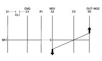
- FIG. 5 is a collinear diagram related to the single motor EV mode.
- reference numerals S1, C1, and R1 indicate the first sun gear 11, the first carrier 14, and the first ring gear 13, respectively.
- Reference numerals S2, C2, and R2 indicate the second sun gear 21 and the second carrier 24, respectively.
- the 2nd ring gear 23 is shown.
- the clutch CL1 and the brake BK1 are released.
- the brake BK1 is opened, the first sun gear 11 is allowed to rotate, and when the clutch CL1 is opened, the first planetary gear mechanism 10 can be differentially operated.
- the HV_ECU 50 causes the second rotary machine MG2 to output a positive torque via the MG_ECU 60 to cause the vehicle 100 to generate a driving force in the forward direction.
- the second ring gear 23 rotates forward in conjunction with the rotation of the drive wheel 32.
- the normal rotation is the rotation direction of the second ring gear 23 when the vehicle 100 moves forward.
- the HV_ECU 50 operates the first rotary machine MG1 as a generator to reduce drag loss.
- the HV_ECU 50 generates a power by applying a slight torque to the first rotating machine MG1, and sets the rotation speed of the first rotating machine MG1 to zero. Thereby, the drag loss of the first rotary machine MG1 can be reduced. Further, even when the MG1 torque is set to 0, the MG1 torque may not be applied if the MG1 rotation speed can be maintained at 0 using the cogging torque. Alternatively, the MG1 rotation speed may be set to 0 by the d-axis lock of the first rotating machine MG1.
- the first ring gear 13 rotates along with the second carrier 24 and rotates forward.
- the neutral state of the first planetary gear mechanism 10 is a state in which no power is transmitted between the first ring gear 13 and the first carrier 14, that is, the engine 1 and the second planetary gear mechanism 20 are disconnected. In this state, power transmission is interrupted.
- the first planetary gear mechanism 10 is connected to connect the engine 1 and the second planetary gear mechanism 20 when at least one of the transmission clutch CL1 and the transmission brake BK1 is engaged.
- the battery When running in the single motor EV mode, the battery may be fully charged and regenerative energy may not be obtained. In this case, it is conceivable to use an engine brake together.
- the clutch CL ⁇ b> 1 or the brake BK ⁇ b> 1 By engaging the clutch CL ⁇ b> 1 or the brake BK ⁇ b> 1, the engine 1 can be connected to the drive wheel 32 and the engine brake can be applied to the drive wheel 32.
- the clutch CL1 or the brake BK1 when the clutch CL1 or the brake BK1 is engaged in the single motor EV mode, the engine 1 is brought into a rotating state, and the engine speed is increased by the first rotating machine MG1 to be in an engine braking state. be able to.
- FIG. 6 is a collinear diagram related to the both-motor EV mode.
- the clutch CL1 When the clutch CL1 is engaged, the differential of the first planetary gear mechanism 10 is restricted, and when the brake BK1 is engaged, the rotation of the first sun gear 11 is restricted. Accordingly, the rotation of all the rotating elements of the first planetary gear mechanism 10 is stopped. By restricting the rotation of the first ring gear 13 that is the output element, the second carrier 24 connected thereto is locked to zero rotation.
- the HV_ECU 50 causes the first rotating machine MG1 and the second rotating machine MG2 to output driving driving torque, respectively. Since the rotation of the second carrier 24 is restricted, the second carrier 24 can take a reaction force against the torque of the first rotating machine MG ⁇ b> 1 and output the torque of the first rotating machine MG ⁇ b> 1 from the second ring gear 23.
- the first rotating machine MG1 can output a positive torque from the second ring gear 23 by outputting a negative torque and rotating negatively when moving forward. On the other hand, at the time of reverse travel, the first rotary machine MG1 can output negative torque from the second ring gear 23 by outputting positive torque and rotating forward.
- FIG. 7 is a collinear diagram related to the HV driving mode in the low state (hereinafter also referred to as “HV low mode”), and FIG. 8 is also referred to as the HV driving mode in the high state (hereinafter referred to as “HV high mode”).
- HV low mode the HV driving mode in the low state
- HV high mode the HV driving mode in the high state
- the HV_ECU 50 engages the clutch CL1 and releases the brake BK1.
- the clutch CL1 is engaged, the differential of the first planetary gear mechanism 10 is restricted, and the rotating elements 11, 13, and 14 rotate integrally. Accordingly, the rotation of the engine 1 is not accelerated or decelerated and is transmitted from the first ring gear 13 to the second carrier 24 at a constant speed.
- the HV_ECU 50 releases the clutch CL1 and engages the brake BK1.
- the engagement of the brake BK1 restricts the rotation of the first sun gear 11. Therefore, the first planetary gear mechanism 10 enters an overdrive (OD) state in which the rotation of the engine 1 input to the first carrier 14 is increased and output from the first ring gear 13.
- the first planetary gear mechanism 10 can increase the rotation speed of the engine 1 and output it.
- the gear ratio of the first planetary gear mechanism 10 during overdrive can be set to 0.7, for example.
- the switching device including the clutch CL1 and the brake BK1 switches between a state in which the differential of the first planetary gear mechanism 10 is regulated and a state in which the differential of the first planetary gear mechanism 10 is allowed to switch.
- the gear mechanism 10 is shifted.
- the hybrid vehicle drive device 1-1 can be switched between the HV high mode and the HV low mode by the transmission unit including the first planetary gear mechanism 10, the clutch CL1, and the brake BK1, and improves the transmission efficiency of the vehicle 100. be able to.
- a second planetary gear mechanism 20 as a differential unit is connected in series with the subsequent stage of the transmission unit. Since the first planetary gear mechanism 10 is overdriven, there is an advantage that the first rotating machine MG1 does not have to be greatly increased in torque.
- the HV_ECU 50 selects the HV high mode at a high vehicle speed, and selects the HV low mode at a medium to low vehicle speed.
- FIG. 9 is a diagram illustrating a map relating to mode selection according to the present embodiment.
- the horizontal axis represents the vehicle speed
- the vertical axis represents the required driving force.
- the low load region where the vehicle speed is low and the required driving force is small is the motor travel region.
- EV travel is selected.
- the single motor EV mode is selected when the load is low, and the dual drive EV mode is selected when the load is high.
- the region where the vehicle speed and load are higher than the motor travel region is the engine travel region.
- the engine travel area is further divided into a direct connection (low) area and an OD (high) area.
- the direct connection region is an engine traveling region where the HV low mode is selected.
- the OD region is an engine traveling region where the HV high mode is selected.
- the OD region is a high vehicle speed region, and the direct connection region is a medium to low vehicle speed region.
- the direct connection area is set on the higher load side than the OD area. The fuel consumption can be improved by overdriving the transmission at high vehicle speed and low load.
- the number of mechanical points becomes two, and the fuel consumption can be improved.
- the mechanical point is a highly efficient operating point in which all the power input to the planetary gear mechanisms 10 and 20 is transmitted to the counter drive gear 25 by mechanical transmission without passing through an electrical path.
- the first planetary gear mechanism 10 can increase the rotation of the engine 1 and output it from the first ring gear 13. Therefore, the hybrid vehicle drive device 1-1 is further provided on the high gear side with respect to the mechanical point when the engine 1 is directly connected to the second carrier 24 without the first planetary gear mechanism 10. Has one mechanical point. That is, the hybrid vehicle drive device 1-1 has two mechanical points on the high gear side. Therefore, the hybrid vehicle drive device 1-1 can realize a hybrid system that can improve fuel efficiency by improving transmission efficiency during high-speed traveling.
- the hybrid vehicle drive device 1-1 can regulate the rotation of the input element of the second planetary gear mechanism 20 by engaging the clutch CL1 and the brake BK1 of the transmission unit, and is based on the dual motor EV mode. It is possible to run. For this reason, it is not necessary to provide a separate clutch or the like in order to realize the both-motor EV mode, and the configuration is simplified.
- the reduction ratio of the second rotary machine MG2 can be increased. Further, a compact arrangement can be realized by the FF or RR layout.
- reverse drive In the case of reverse travel, during engine travel, the first rotary machine MG1 generates power as a generator, the second rotary machine MG2 powers as a motor, travels negatively, outputs negative torque, and travels. When the state of charge of the battery is sufficient, the second rotary machine MG2 may independently rotate in the single drive EV mode to run on the motor. It is also possible to drive backward with the second carrier 24 fixed and in the double drive EV mode.
- the HV_ECU 50 can execute coordinated shift control that simultaneously shifts the first planetary gear mechanism 10 and the second planetary gear mechanism 20.
- the HV_ECU 50 increases one gear ratio of the first planetary gear mechanism 10 and the second planetary gear mechanism 20 and decreases the other gear ratio.
- HV_ECU 50 changes the gear ratio of second planetary gear mechanism 20 to the high gear side in synchronization with the mode switching when switching from the HV high mode to the HV low mode.
- the discontinuous change of the gear ratio in the whole from the engine 1 of the vehicle 100 to the drive wheel 32 can be suppressed or reduced, and the degree of the change of the gear ratio can be reduced.
- the HV_ECU 50 shifts the first planetary gear mechanism 10 and the second planetary gear mechanism 20 in a coordinated manner so as to continuously change the gear ratio of the entire vehicle 100 to the low side.
- the HV_ECU 50 when switching from the HV low mode to the HV high mode, changes the gear ratio of the second planetary gear mechanism 20 to the low gear side in synchronization with the mode switching. Thereby, the discontinuous change of the gear ratio in the entire vehicle 100 can be suppressed or reduced, and the degree of change of the gear ratio can be reduced.
- the HV_ECU 50 shifts the first planetary gear mechanism 10 and the second planetary gear mechanism 20 in a coordinated manner so as to continuously change the gear ratio of the entire vehicle 100 to the high side.
- the adjustment of the gear ratio of the second planetary gear mechanism 20 is performed, for example, by controlling the rotational speed of the first rotating machine MG1.
- the HV_ECU 50 controls the first rotary machine MG1 so as to change the speed ratio between the input shaft 2 and the counter drive gear 25 steplessly.
- the entire transmission including the planetary gear mechanisms 10, 20, the first rotating machine MG1, the clutch CL1, and the brake BK1, that is, the transmission including the differential unit and the transmission unit operates as an electric continuously variable transmission. Since the gear ratio range of the transmission including the differential unit and the transmission unit is wide, the gear ratio from the differential unit to the drive wheels 32 can be made relatively large. Further, power circulation during high vehicle speed traveling in the HV traveling mode is reduced.
- the hybrid vehicle drive device 1-1 uses the first rotating machine MG1 to fix the engine 1 while the gear position of the transmission unit is fixed when the engine 1 is stopped while the engine 1 is running as a power source. And after the engine 1 is stopped, the transmission unit is made neutral. At this time, the engine stop position control described below can be performed with the gear stage fixed. The engine stop position control is facilitated by stopping the engine 1 in a state where there is no speed change with the gear stage fixed.
- the first rotating machine MG1 In order to stop the engine 1 by the first rotating machine MG1, for example, the first rotating machine MG1 generates a torque in a direction opposite to the rotation direction of the engine 1 after the fuel supply to the engine 1 is stopped, This includes generating torque in the rotational direction of the engine 1 by the first rotating machine MG1. Further, stopping the engine 1 by the first rotating machine MG1 includes changing the engine speed and the rotation angle of the engine 1 until the engine 1 stops by the torque of the first rotating machine MG1.
- Securing the shift stage of the transmission unit includes maintaining the current shift stage and not performing a shift.
- fixing the shift stage of the transmission unit includes fixing the shift stage of the transmission unit to a predetermined shift stage. In this case, if the current shift speed is not the predetermined shift speed, the shift to the predetermined shift speed is included, and thereafter the predetermined shift speed is maintained.
- the hybrid vehicle drive device 1-1 can execute engine stop position control for controlling the stop position of the engine 1 when the engine 1 is stopped during HV traveling or the like.
- the stop position of the engine 1 is controlled by the first rotating machine MG1 in a state in which the speed stage of the transmission unit is fixed so that the engine 1 is stopped at a predetermined crank angle.
- the predetermined crank angle is set, for example, as a crank angle that can minimize a shock that occurs when the engine 1 is restarted next time.
- the predetermined crank angle is a crank angle at which a reaction force due to air in the cylinder is minimized when the engine 1 starts rotating at the time of restart.
- the predetermined crank angle is, for example, a crank angle at which the piston stops during expansion during the expansion stroke, or a crank angle at which the piston stops during compression during the compression stroke.
- the engine speed reduction control is a control that promotes the reduction of the engine speed when the engine 1 is stopped during HV traveling or the like. Specifically, a decrease in engine speed is promoted by outputting torque (negative torque) in a direction that restricts engine rotation by the first rotating machine MG1. Due to the engine speed reduction control, the engine speed when the engine is stopped decreases quickly after passing through the rotational speed range of the resonance point of the engine 1. Thereby, the shock at the time of an engine stop is suppressed.
- the first rotating machine MG1 functions as a generator by generating negative torque and rotating positively. Therefore, in the engine speed reduction control, the rotational energy of the engine 1 can be recovered as electric energy and charged to the battery.
- the hybrid vehicle drive device 1-1 of the present embodiment performs engine stop position control when the magnitude of the differential rotation speed of the second planetary gear mechanism 20 is equal to or less than a predetermined value.
- “when the magnitude of the differential rotational speed of the second planetary gear mechanism 20 is equal to or smaller than a predetermined value” means, for example, the second planetary gear until the rotation of the engine 1 is stopped by engine stop position control.
- the predetermined value for the magnitude of the differential rotation speed of the second planetary gear mechanism 20 is determined based on, for example, the maximum allowable value for the magnitude of the differential rotation speed of the second planetary gear mechanism 20.
- the predetermined value is determined from the viewpoint of loss generated in the second planetary gear mechanism 20 and durability of the second planetary gear mechanism 20, for example.
- FIG. 10 is a diagram showing an implementation range of engine speed reduction control.
- the horizontal axis indicates the vehicle speed
- the vertical axis indicates the engine speed.
- the HV_ECU 50 executes engine speed reduction control and engine stop position control, respectively.
- the HV_ECU 50 controls the rotation angle of the engine 1 so that the first rotation machine MG1 reduces the engine rotation speed, and when the engine 1 stops, the first rotation machine MG1 sets the crank angle of the engine 1 to a predetermined crank angle. To do.
- the HV_ECU 50 ends the engine speed reduction control when the engine speed decreases to the predetermined speed NE1.
- the predetermined vehicle speed V1 of the present embodiment is determined as a vehicle speed at which the differential rotation speed of the second planetary gear mechanism 20 becomes a predetermined upper limit value.
- the predetermined rotational speed NE1 is the difference rotational speed of the second planetary gear mechanism 20 when the rotational speed of the first rotating machine MG1 is changed in conjunction with the engine rotational speed by engine rotational speed reduction control or engine stop position control. This is the engine speed at which the magnitude becomes a predetermined value.
- HV_ECU 50 releases the clutch CL1 and the brake BK1 and sets the transmission unit to neutral in the region of the engine speed lower than the predetermined speed NE1.
- the transmission of the engine 1 and the first rotary machine MG1 or the second rotary machine MG2 is interrupted by setting the transmission unit to neutral. Therefore, if the speed change portion is neutral, there is no need to change the rotational speed of the first rotating machine MG1 in conjunction with a decrease in the engine rotational speed, and the differential rotational speed of the planetary gear mechanisms 10 and 20 may become excessive. It is suppressed.
- FIG. 11 is a time chart relating to the operation of the hybrid vehicle drive device 1-1 of the present embodiment.
- step S10 the HV_ECU 50 determines whether or not an engine stop determination has been made.
- the HV_ECU 50 determines whether or not a condition for stopping the engine 1 is established during traveling in the HV mode using the engine 1 as a power source. For example, based on the map shown in FIG. 9, when the operating point has shifted from the engine travel area to the motor travel area, an engine stop determination is made. In FIG. 11, the engine stop determination is made at time t1 when the accelerator opening is decreased to ⁇ 1, and an affirmative determination is made in step S10.
- the HV_ECU 50 executes a fuel cut that stops the fuel supply to the engine 1.
- the MG1 torque after time t1 is changed from the reaction torque against the engine torque so far to a torque that decreases the engine speed.
- the HV_ECU 50 causes the first rotating machine MG1 to output a negative torque and promotes a decrease in the engine speed.
- step S10 if it is determined that the engine stop determination is made (step S10-Y), the process proceeds to step S20, and if not (step S10-N), the process proceeds to step S110.
- step S20 the HV_ECU 50 determines whether or not the positional relationship has been learned (origin has been adjusted).
- This positional relationship is a positional relationship between the crank angle of the engine 1 and the rotation angle of the first rotary machine MG1.
- the engine 1 and the first rotating machine MG1 are connected via a transmission unit. For this reason, when the transmission unit is set to neutral or the transmission unit is shifted, a shift occurs in the correspondence relationship between the crank angle of the engine 1 and the rotation angle of the first rotary machine MG1. In this case, it is necessary to relearn the positional relationship.
- the hybrid vehicle drive device 1-1 has a sensor for detecting the crank angle of the engine 1 and a sensor for detecting the rotation angle of the first rotating machine MG1 (for example, an MG1 rotation speed sensor).
- the HV_ECU 50 can learn the positional relationship based on the detection results of these sensors. In this learning control, for example, the phase difference between the origin of the crank angle and the origin of the rotation angle of the first rotary machine MG1 is learned.
- the learning of the positional relationship is appropriately executed when the positional relationship has not been learned. For example, the positional relationship is learned when one of the shift stages is formed from neutral in the transmission unit or when a shift is executed.
- step S20 if it is determined that the positional relationship has been learned (step S20-Y), the process proceeds to step S40, and if not (step S20-N), the process proceeds to step S30.
- step S30 the HV_ECU 50 performs learning while fixing the gear position.
- the HV_ECU 50 learns the relationship between the crank angle of the engine 1 and the rotation angle of the first rotary machine MG1 in a state where the shift of the transmission unit is prohibited and the shift stage of the transmission unit is fixed. For example, when it is determined that the engine is stopped during a shift, a gear position is once formed and the angular relationship is learned. That is, the relationship between the crank angle of the engine 1 and the rotation angle of the first rotary machine MG1 is learned in a state where the gear position of the transmission unit is fixed to the gear position in the HV low mode or the gear position in the HV high mode.
- step S30 the process proceeds to step S40.
- step S40 the HV_ECU 50 prohibits shifting.
- the HV_ECU 50 prohibits shifting of the transmission unit so that the correspondence relationship between the crank angle and the rotation angle of the first rotating machine MG1 does not change from the learned one.
- step S50 the HV_ECU 50 determines whether or not the vehicle speed is higher than a predetermined vehicle speed V1. As a result of the determination, if it is determined that the vehicle speed is greater than the predetermined vehicle speed V1 (step S50-Y), the process proceeds to step S60, and if not (step S50-N), the process proceeds to step S80.
- step S60 the HV_ECU 50 executes the engine speed reduction control and does not execute the engine stop position control.
- the HV_ECU 50 executes the engine speed reduction control and promotes the engine speed reduction by the first rotating machine MG1.
- the process proceeds to step S70.
- step S70 the HV_ECU 50 executes neutral control.
- the HV_ECU 50 releases the clutch CL1 and the brake BK1, and sets the transmission unit to neutral.
- the process proceeds to step S100.
- step S80 the engine speed reduction control and the engine stop position control are executed by the HV_ECU 50, respectively.
- the HV_ECU 50 promotes a decrease in the engine speed through the engine speed reduction control.
- the engine speed reduction control is started at time t1.
- the HV_ECU 50 controls the stop position of the engine 1 by the first rotating machine MG1 so that the engine 1 stops at a predetermined crank angle when the rotation of the engine 1 stops.
- the engine stop position control is started, for example, when the engine speed becomes a predetermined speed or less.
- the engine stop position control is started at time t3.
- the HV_ECU 50 makes the engine rotation speed decrease rate in the engine stop position control smaller than the engine rotation speed decrease rate in the engine rotation speed decrease control. For example, the HV_ECU 50 reduces the decrease rate of the engine speed by setting the MG1 torque in the engine stop position control to a positive torque.
- the HV_ECU 50 controls the rotation angle of the engine 1 with the MG1 torque so as to stop the engine 1 at a predetermined crank angle.
- the engine stop position control ends when the engine 1 stops at a predetermined crank angle.
- the HV_ECU 50 sets the MG1 torque to 0 when the engine stop position control ends. In FIG. 11, the engine stop position control ends at time t4. When the engine stop position control ends, the process proceeds to step S90.
- step S90 the HV_ECU 50 executes neutral control.
- the HV_ECU 50 releases the clutch CL1 and the brake BK1, and sets the transmission unit to neutral. In other words, the transmission unit is neutral after the engine 1 is stopped.
- the hydraulic pressure supplied to the brake BK1 that has been engaged until time t4 decreases, the brake BK1 is released, and both the clutch CL1 and the brake BK1 are released by time t5.
- the process proceeds to step S100.
- step S100 the HV_ECU 50 executes control for setting the rotation speed of the first rotating machine MG1 to zero.
- Neutral control is executed in step S70 or step S90, and the rotational speed of the first rotating machine MG1 can be changed regardless of the engine rotational speed.
- the HV_ECU 50 changes the rotation speed of the first rotary machine MG1 to 0 rotation.
- the rotation of the first rotating machine MG1 can be stopped by causing the first rotating machine MG1 that is rotating negatively to output a positive torque.
- the first rotating machine MG1 may idle and the rotation of the first rotating machine MG1 may be stopped by friction.
- the rotation speed of the first rotating machine MG1 changes to 0 from time t5 to time t6.
- step S100 completes a series of controls related to engine stop, and the transition to the motor travel mode is completed.
- HV_ECU 50 outputs MG2 torque and causes vehicle 100 to travel by motor.
- step S110 If a negative determination is made in step S10 and the process proceeds to step S110, the engine running is continued by the HV_ECU 50 in step S110.
- the HV_ECU 50 continues the operation of the engine 1 and causes the vehicle 100 to travel in the HV low mode or the HV high mode.
- step S110 is executed, the control flow ends.
- the hybrid vehicle drive device 1-1 of the present embodiment sets the transmission unit to neutral after completion of the engine stop position control by the first rotating machine MG1. Thereby, the engine 1 can be stopped at an appropriate rotation angle. Therefore, the restartability of the engine 1 can be improved and the shock during engine restart can be reduced.
- the hybrid vehicle drive device 1-1 stops the engine 1 by the first rotating machine MG1 in a state where the correspondence relationship between the crank angle of the engine 1 and the rotating angle of the first rotating machine MG1 has been learned.
- engine stop position control is preferably executed. Thereby, the stop position control of the crank angle can be performed with high accuracy.
- the gear position is once formed in the gear shifting portion, and the engine stop position control is executed after learning the angular relationship. Therefore, the engine 1 can be stopped at a desired crank angle.
- the hybrid vehicle drive device 1-1 does not execute the engine stop position control when the engine stop determination is made at a vehicle speed higher than the predetermined vehicle speed V1. Thereby, it can suppress that the pinion relative rotational speed (differential rotational speed) of the 2nd planetary gear mechanism 20 becomes excessive. Further, when engine stop determination is made at a vehicle speed equal to or lower than the predetermined vehicle speed V1, the engine 1 is stopped by the first rotating machine MG1 with the gear position of the transmission unit fixed. As a result, the engine 1 can be stopped while suppressing the pinion relative rotational speed (differential rotational speed) of the second planetary gear mechanism 20 from becoming excessive. When the engine 1 is stopped, the engine stop position control is preferably executed by the first rotating machine MG1.
- the engine speed reduction control is executed until the engine speed decreases to the predetermined speed NE1. Therefore, the engine speed is reduced by quickly passing through the resonance speed range, thereby reducing vibration when the engine is stopped.
- the transmission unit is set to neutral, and the MG1 rotation speed is set to zero. Thereby, the efficiency fall by the friction etc. of the 1st rotary machine MG1 is suppressed.
- the MG1 torque may be changed according to the gear position of the transmission unit.
- the MG1 torque is determined so that the time from when the engine stop is determined until the rotation of the engine 1 stops is the same time regardless of the gear position.
- the MG1 torque may be determined such that the rate of decrease in engine speed is constant regardless of the gear position.
- the engine 1 when the engine 1 is a supercharged engine, the engine 1 may be shifted to engine speed reduction control or engine stop position control after the supercharging pressure is reduced. Thereby, since the compression reaction force of an engine can be reduced, the vibration at the time of an engine stop is reduced.
- FIG. 12 is a skeleton diagram of a vehicle according to a modification of the embodiment
- FIG. 13 is a diagram illustrating an operation engagement table of a hybrid vehicle drive device according to the modification of the embodiment.
- the hybrid vehicle drive device 1-2 of the present modification differs from the hybrid vehicle drive device 1-1 of the above embodiment in that the second planetary gear mechanism 20 functions as a transmission unit.
- the first carrier 14 of the first planetary gear mechanism 10 is connected to the engine 1 and the first ring gear 13 is connected to the second planetary gear mechanism 20 in the same manner as in the above embodiment.
- the second carrier 24 is connected.
- the first sun gear 11 of the first planetary gear mechanism 10 is connected to the rotating shaft 33 of the first rotating machine MG1. Therefore, the first planetary gear mechanism 10 can function as a power split mechanism that splits the output torque of the engine 1 into the first rotary machine MG1 side and the output side.
- the first planetary gear mechanism 10 functions as a differential unit that can change the rotational speed ratio between the engine 1 (first carrier 14) and the first ring gear 13 steplessly together with the first rotating machine MG1. can do.
- the counter drive gear 25 is connected to the second ring gear 23 of the second planetary gear mechanism 20.
- a brake BK ⁇ b> 1 is connected to the second sun gear 21.
- the brake BK1 is a brake device that can regulate the rotation of the second sun gear 21.
- the brake BK1 of this modification can have the same configuration as the brake BK1 of the above embodiment.
- the clutch CL1 according to this modification is a clutch device capable of connecting the second sun gear 21 and the second carrier 24.
- the clutch CL1 of this modification can have the same configuration as the clutch CL1 of the above embodiment.
- the switching device including the clutch CL1 and the brake BK1 switches the state of restricting the differential of the second planetary gear mechanism 20 and the state of allowing the differential of the second planetary gear mechanism 20 to switch the second planetary gear mechanism 20. Change speed. That is, the second planetary gear mechanism 20 of the present modification functions as a transmission unit.
- the hybrid vehicle drive device 1-2 of this modification is different from the hybrid vehicle drive device 1-1 (see FIG. 4) of the above embodiment and does not have the dual motor EV mode. .
- the engagement / release states of the clutch CL1 and the brake BK1 in the other modes are the same as those in the above embodiment.
- the hybrid vehicle drive device 1-2 when the brake BK1 and the clutch CL1 are released and the speed change unit is neutral, the power transmission path between the first ring gear 13 and the drive wheels 32 is cut off. The In this case, power transmission between the engine 1 and the first rotary machine MG1 is also interrupted. In the single motor EV mode, by releasing the brake BK1 and the clutch CL1, the second rotary machine MG2, the drive wheel 32, and the engine 1 can be disconnected, and the second rotary machine MG2 can be used as a power source.
- the brake BK1 or the clutch CL1 when the brake BK1 or the clutch CL1 is engaged, the power transmission path between the first ring gear 13 and the drive wheels 32 is connected.
- the brake BK1 when the brake BK1 is engaged and the clutch CL1 is released (HV high mode), the rotation of the second sun gear 21 is restricted.
- the first ring gear 13 is connected to the drive wheels 32 through the second carrier 24, the second pinion gear 22, and the second ring gear 23 so that power can be transmitted. Therefore, the first rotary machine MG1 and the engine 1 are connected so that power can be transmitted.
- the first rotating machine MG1 functions as a reaction force receiver of the engine 1 and can output engine torque from the first ring gear 13 to the drive wheels 32.
- the brake BK1 As the brake BK1 is engaged, the engine speed input to the second carrier 24 is increased and output from the second ring gear 23.
- the differential of the second planetary gear mechanism 20 is restricted.
- the first ring gear 13 is connected to the drive wheels 32 through the second carrier 24, the second pinion gear 22, and the second ring gear 23 so that power can be transmitted. Therefore, the first rotary machine MG1 and the engine 1 are connected so that power can be transmitted.
- the first rotating machine MG1 functions as a reaction force receiver of the engine 1 and can output engine torque from the first ring gear 13 to the drive wheels 32. Since the clutch CL1 is engaged, the engine rotation input to the second carrier 24 is output from the second ring gear 23 without being accelerated or decelerated.
- the hybrid vehicle drive device 1-2 is subjected to engine speed reduction control and engine stop position control in the same manner as the hybrid vehicle drive device 1-1 of the above embodiment.
- the HV_ECU 50 of this modification can execute the same control (see FIG. 1) as the HV_ECU 50 of the above embodiment. If the positional relationship has not been learned (S20-N), the engine speed is fixed and the learning is executed (S30), and then the engine stop position control is executed (S80). Further, the engine stop position control is performed when the magnitude of the differential rotation speed of the first planetary gear mechanism 10 is equal to or smaller than a predetermined value (S50-N).
- an engine, a first transmission unit, and a differential unit are used, and an electric continuously variable transmission unit is formed by the first rotating machine (electric motor) and the second rotating machine (electric motor).
- a power transmission device (a hybrid vehicle drive device) is disclosed in which a first transmission unit is set to neutral after completion of engine stop position control by a rotating machine. According to this power transmission device, it is possible to reduce the shock at the time of restart by improving the accuracy of the stop position control.
Abstract
Description
図1から図11を参照して、実施形態について説明する。本実施形態は、ハイブリッド車両用駆動装置に関する。図1は、本発明の実施形態に係るハイブリッド車両用駆動装置の動作を示すフローチャート、図2は、実施形態に係る車両のスケルトン図、図3は、実施形態に係る車両の入出力関係図、図4は、実施形態に係るハイブリッド車両用駆動装置の作動係合表を示す図である。
後進走行をする場合、エンジン走行中は、第一回転機MG1がジェネレータとして発電を行い、第二回転機MG2がモータとして力行し、負回転して負トルクを出力して走行する。バッテリの充電状態が十分であるときは、単独駆動EVモードで第二回転機MG2が単独で逆回転してモータ走行するようにしてもよい。また、第二キャリア24を固定して両駆動EVモードで後進走行することも可能である。
HV_ECU50は、HVハイモードとHVローモードとの切り替えを行う場合、第一遊星歯車機構10と第二遊星歯車機構20とを同時に変速させる協調変速制御を実行することができる。HV_ECU50は、協調変速制御において、第一遊星歯車機構10および第二遊星歯車機構20の一方の変速比を増加させ、他方の変速比を減少させる。
単独モータEVモードからエンジン1を始動する場合、クラッチCL1あるいはブレーキBK1を係合し、第一回転機MG1によってエンジン回転数を上昇させて点火を行う。このときに、クラッチCL1あるいはブレーキBK1を係合する前に、第一回転機MG1の回転数制御によって、第二キャリア24(第一リングギア13)の回転数を0回転とするようにしてもよい。また、MG1トルクによってエンジン回転数を上昇させるときに、走行駆動力を低下させる方向の反力トルクが発生する。HV_ECU50は、この反力トルクをキャンセルする反力キャンセルトルクを第二回転機MG2に追加で出力させるようにしてもよい。なお、エンジン1が直噴エンジンなど自立的に始動可能なものである場合、自立的にエンジン1を始動させてもよく、エンジン1の自立始動をMG1トルクによってアシストするようにしてもよい。
本実施形態に係るハイブリッド車両用駆動装置1-1は、エンジン1を動力源として走行中にエンジン1を停止するときに、変速部の変速段を固定した状態で第一回転機MG1によってエンジン1を停止し、エンジン1の停止後に変速部を中立とする。このときに、変速段を固定した状態で以下に説明するエンジン停止位置制御を行うことができる。変速段を固定して変速がない状態でエンジン1を停止することで、エンジン停止位置制御が容易になる。
本実施形態に係るハイブリッド車両用駆動装置1-1は、HV走行中等にエンジン1を停止するときに、エンジン1の停止位置を制御するエンジン停止位置制御を実行することができる。エンジン停止位置制御は、エンジン1を予め定められた所定のクランク角度で停止させるように、変速部の変速段を固定した状態で第一回転機MG1によってエンジン1の停止位置を制御するものである。所定のクランク角度は、例えば、次回エンジン1を再始動するときに発生するショックを最小とすることができるクランク角度として設定される。例えば、所定のクランク角度は、再始動時にエンジン1が回転を始める時の筒内の空気による反力が最小となるクランク角度である。回転に対する反力が小さいことで、エンジン回転数の上昇が速くなる。その結果、再始動時に、エンジン回転数がエンジン1の共振点の回転数域を素早く抜けて上昇することで、始動に伴うショックが抑制される。所定のクランク角度は、一例として、膨張行程の膨張途中でピストンが停止するクランク角度や、圧縮行程の圧縮途中でピストンが停止するクランク角度とされる。
また、ハイブリッド車両用駆動装置1-1は、エンジン回転数低下制御を実行することができる。エンジン回転数低下制御は、HV走行中等にエンジン1を停止するときにエンジン回転数の低下を促進する制御である。具体的には、第一回転機MG1によってエンジン回転を規制する方向のトルク(負トルク)を出力させることにより、エンジン回転数の低下を促進する。エンジン回転数低下制御により、エンジン停止時のエンジン回転数は、エンジン1の共振点の回転数域を素早く抜けて低下する。これにより、エンジン停止時のショックが抑制される。また、エンジン回転数低下制御では、第一回転機MG1は負トルクを発生して正回転することで、発電機として機能する。従って、エンジン回転数低下制御では、エンジン1の回転エネルギーを電気エネルギーとして回収し、バッテリに充電することができる。
実施形態の変形例について説明する。図12は、実施形態の変形例に係る車両のスケルトン図、図13は、実施形態の変形例に係るハイブリッド車両用駆動装置の作動係合表を示す図である。本変形例のハイブリッド車両用駆動装置1-2において、上記実施形態のハイブリッド車両用駆動装置1-1と異なる点は、第二遊星歯車機構20が変速部として機能する点である。
1 エンジン
10 第一遊星歯車機構
20 第二遊星歯車機構
100 車両
MG1 第一回転機
MG2 第二回転機
Claims (4)
- 機関と、
回転機と、
前記機関と前記回転機とを断接する変速部と
を備え、
前記機関を動力源として走行中に前記機関を停止するときに、前記変速部の変速段を固定した状態で前記回転機によって前記機関を停止し、前記機関の停止後に前記変速部を中立とする
ことを特徴とするハイブリッド車両用駆動装置。 - 前記機関の回転角度と前記回転機の回転角度との対応関係を学習済みの状態で前記回転機によって前記機関を停止する
請求項1に記載のハイブリッド車両用駆動装置。 - 前記変速部の変速段によらず前記機関が停止するまでの時間を同一とするように前記回転機のトルクを制御する
請求項1または2に記載のハイブリッド車両用駆動装置。 - 前記機関と前記回転機とが差動機構を介して接続されており、
前記差動機構の差回転数の大きさを所定値よりも大とすることなく前記機関を停止可能な場合に、前記変速部の変速段を固定した状態で前記回転機によって前記機関を停止する
請求項1に記載のハイブリッド車両用駆動装置。
Priority Applications (5)
| Application Number | Priority Date | Filing Date | Title |
|---|---|---|---|
| PCT/JP2012/065393 WO2013186924A1 (ja) | 2012-06-15 | 2012-06-15 | ハイブリッド車両用駆動装置 |
| DE112012006525.5T DE112012006525T5 (de) | 2012-06-15 | 2012-06-15 | Hybridfahrzeug-Antriebsvorrichtung |
| US14/407,694 US20150166042A1 (en) | 2012-06-15 | 2012-06-15 | Hybrid Vehicle Driving Device |
| CN201280073998.7A CN104379423A (zh) | 2012-06-15 | 2012-06-15 | 混合动力车辆用驱动装置 |
| JP2014521086A JPWO2013186924A1 (ja) | 2012-06-15 | 2012-06-15 | ハイブリッド車両用駆動装置 |
Applications Claiming Priority (1)
| Application Number | Priority Date | Filing Date | Title |
|---|---|---|---|
| PCT/JP2012/065393 WO2013186924A1 (ja) | 2012-06-15 | 2012-06-15 | ハイブリッド車両用駆動装置 |
Publications (1)
| Publication Number | Publication Date |
|---|---|
| WO2013186924A1 true WO2013186924A1 (ja) | 2013-12-19 |
Family
ID=49757785
Family Applications (1)
| Application Number | Title | Priority Date | Filing Date |
|---|---|---|---|
| PCT/JP2012/065393 WO2013186924A1 (ja) | 2012-06-15 | 2012-06-15 | ハイブリッド車両用駆動装置 |
Country Status (5)
| Country | Link |
|---|---|
| US (1) | US20150166042A1 (ja) |
| JP (1) | JPWO2013186924A1 (ja) |
| CN (1) | CN104379423A (ja) |
| DE (1) | DE112012006525T5 (ja) |
| WO (1) | WO2013186924A1 (ja) |
Cited By (7)
| Publication number | Priority date | Publication date | Assignee | Title |
|---|---|---|---|---|
| WO2015106739A1 (de) * | 2014-01-16 | 2015-07-23 | Schaeffler Technologies AG & Co. KG | Elektromechanische anlasseranordnung für eine brennkraftmaschine |
| JPWO2013186924A1 (ja) * | 2012-06-15 | 2016-02-01 | トヨタ自動車株式会社 | ハイブリッド車両用駆動装置 |
| JP2016094153A (ja) * | 2014-11-17 | 2016-05-26 | トヨタ自動車株式会社 | 車両の駆動装置 |
| JP2017222298A (ja) * | 2016-06-16 | 2017-12-21 | 日産自動車株式会社 | 車両の駆動力制御方法および駆動力制御装置 |
| JP2017222217A (ja) * | 2016-06-13 | 2017-12-21 | トヨタ自動車株式会社 | 車両の制御装置 |
| JP2019055712A (ja) * | 2017-09-21 | 2019-04-11 | トヨタ自動車株式会社 | 車両の制御装置 |
| JP2020189592A (ja) * | 2019-05-23 | 2020-11-26 | 本田技研工業株式会社 | ハイブリッド車両の駆動装置 |
Families Citing this family (6)
| Publication number | Priority date | Publication date | Assignee | Title |
|---|---|---|---|---|
| JP5874814B2 (ja) * | 2012-03-26 | 2016-03-02 | トヨタ自動車株式会社 | ハイブリッド車両の駆動制御装置 |
| DE102014016873A1 (de) * | 2014-11-15 | 2016-05-19 | Daimler Ag | Verfahren zum Betrieb eines Kraftfahrzeugs und Kraftfahrzeug |
| WO2019116556A1 (ja) * | 2017-12-15 | 2019-06-20 | 日産自動車株式会社 | ハイブリッド車両の制御方法及び制御装置 |
| DE102019103689A1 (de) * | 2019-02-14 | 2020-08-20 | Bayerische Motoren Werke Aktiengesellschaft | Verfahren zum Betreiben eines Hybridelektrokraftfahrzeugs, Steuereinrichtung sowie Hybridelektrokraftfahrzeug |
| KR102621233B1 (ko) * | 2019-07-24 | 2024-01-05 | 현대자동차 주식회사 | 수동 변속기가 장착된 차량의 isg 기능 제어 방법 및 그 방법이 적용된 차량 |
| CN112829739B (zh) * | 2019-11-22 | 2023-04-07 | 广州汽车集团股份有限公司 | 混合动力驱动装置的工作模式控制方法和混合动力系统 |
Citations (3)
| Publication number | Priority date | Publication date | Assignee | Title |
|---|---|---|---|---|
| JP2008120233A (ja) * | 2006-11-10 | 2008-05-29 | Toyota Motor Corp | ハイブリッド駆動装置 |
| JP2009298269A (ja) * | 2008-06-12 | 2009-12-24 | Toyota Motor Corp | ハイブリッド車両の制御装置 |
| JP2010155495A (ja) * | 2008-12-26 | 2010-07-15 | Aisin Aw Co Ltd | 車両制御装置 |
Family Cites Families (11)
| Publication number | Priority date | Publication date | Assignee | Title |
|---|---|---|---|---|
| JP3578071B2 (ja) * | 2000-09-14 | 2004-10-20 | トヨタ自動車株式会社 | 可変気筒エンジンの制御装置および車両の制御装置 |
| JP4075508B2 (ja) * | 2002-08-02 | 2008-04-16 | トヨタ自動車株式会社 | 内燃機関の制御装置 |
| US7524266B2 (en) * | 2005-09-30 | 2009-04-28 | Mazda Motor Corporation | Engine starting system for power train |
| JP2010125900A (ja) * | 2008-11-25 | 2010-06-10 | Aisin Aw Co Ltd | ハイブリッド駆動装置 |
| CN102421649B (zh) * | 2009-05-12 | 2015-04-22 | 丰田自动车株式会社 | 混合动力车辆的控制装置 |
| JP5267677B2 (ja) * | 2009-11-13 | 2013-08-21 | トヨタ自動車株式会社 | ハイブリッド車およびその制御方法 |
| US8241173B2 (en) * | 2010-01-12 | 2012-08-14 | GM Global Technology Operations LLC | Single motor hybrid transmission |
| JP5353781B2 (ja) * | 2010-03-18 | 2013-11-27 | 三菱自動車工業株式会社 | ハイブリッド車のエンジン制御装置 |
| JP2012056510A (ja) * | 2010-09-10 | 2012-03-22 | Aisin Seiki Co Ltd | ハイブリッド車両の駆動装置 |
| JP5589922B2 (ja) * | 2011-03-24 | 2014-09-17 | アイシン精機株式会社 | ハイブリッド車両のクラッチ制御装置 |
| US20150166042A1 (en) * | 2012-06-15 | 2015-06-18 | Toyota Jidosha Kabushiki Kaisha | Hybrid Vehicle Driving Device |
-
2012
- 2012-06-15 US US14/407,694 patent/US20150166042A1/en not_active Abandoned
- 2012-06-15 DE DE112012006525.5T patent/DE112012006525T5/de not_active Withdrawn
- 2012-06-15 WO PCT/JP2012/065393 patent/WO2013186924A1/ja active Application Filing
- 2012-06-15 CN CN201280073998.7A patent/CN104379423A/zh active Pending
- 2012-06-15 JP JP2014521086A patent/JPWO2013186924A1/ja active Pending
Patent Citations (3)
| Publication number | Priority date | Publication date | Assignee | Title |
|---|---|---|---|---|
| JP2008120233A (ja) * | 2006-11-10 | 2008-05-29 | Toyota Motor Corp | ハイブリッド駆動装置 |
| JP2009298269A (ja) * | 2008-06-12 | 2009-12-24 | Toyota Motor Corp | ハイブリッド車両の制御装置 |
| JP2010155495A (ja) * | 2008-12-26 | 2010-07-15 | Aisin Aw Co Ltd | 車両制御装置 |
Cited By (7)
| Publication number | Priority date | Publication date | Assignee | Title |
|---|---|---|---|---|
| JPWO2013186924A1 (ja) * | 2012-06-15 | 2016-02-01 | トヨタ自動車株式会社 | ハイブリッド車両用駆動装置 |
| WO2015106739A1 (de) * | 2014-01-16 | 2015-07-23 | Schaeffler Technologies AG & Co. KG | Elektromechanische anlasseranordnung für eine brennkraftmaschine |
| JP2016094153A (ja) * | 2014-11-17 | 2016-05-26 | トヨタ自動車株式会社 | 車両の駆動装置 |
| JP2017222217A (ja) * | 2016-06-13 | 2017-12-21 | トヨタ自動車株式会社 | 車両の制御装置 |
| JP2017222298A (ja) * | 2016-06-16 | 2017-12-21 | 日産自動車株式会社 | 車両の駆動力制御方法および駆動力制御装置 |
| JP2019055712A (ja) * | 2017-09-21 | 2019-04-11 | トヨタ自動車株式会社 | 車両の制御装置 |
| JP2020189592A (ja) * | 2019-05-23 | 2020-11-26 | 本田技研工業株式会社 | ハイブリッド車両の駆動装置 |
Also Published As
| Publication number | Publication date |
|---|---|
| DE112012006525T5 (de) | 2015-03-12 |
| US20150166042A1 (en) | 2015-06-18 |
| CN104379423A (zh) | 2015-02-25 |
| JPWO2013186924A1 (ja) | 2016-02-01 |
Similar Documents
| Publication | Publication Date | Title |
|---|---|---|
| JP6801617B2 (ja) | 車両の制御装置 | |
| WO2013186924A1 (ja) | ハイブリッド車両用駆動装置 | |
| EP2810806B1 (en) | Drive apparatus for hybrid vehicle | |
| JP6015770B2 (ja) | ハイブリッド車両用駆動装置 | |
| JP5892180B2 (ja) | ハイブリッド車両用駆動装置 | |
| JP5991374B2 (ja) | ハイブリッド車両の動力伝達装置及びハイブリッドシステム | |
| JP6075376B2 (ja) | ハイブリッド車両用駆動装置 | |
| JP5892256B2 (ja) | ハイブリッド車両の動力伝達装置及びハイブリッドシステム | |
| JP5904279B2 (ja) | ハイブリッド車両の動力伝達装置及びハイブリッドシステム | |
| JP6888497B2 (ja) | 車両用動力伝達装置の制御装置 | |
| JP6115572B2 (ja) | 動力伝達装置 | |
| JP6040886B2 (ja) | 動力伝達装置 | |
| JP2014051146A (ja) | ハイブリッド車両用駆動装置 | |
| JP6891748B2 (ja) | 車両の制御装置 | |
| JP5929641B2 (ja) | ハイブリッド車両用駆動装置 | |
| JP6015489B2 (ja) | ハイブリッド車両用駆動装置 | |
| JP2015020725A (ja) | ハイブリッド車両用駆動装置 | |
| JP6911667B2 (ja) | 車両用動力伝達装置の制御装置 | |
| WO2014080529A1 (ja) | ハイブリッド車両用駆動装置 | |
| JP2015174554A (ja) | ハイブリッド車両用駆動装置の制御装置 | |
| JP2015024761A (ja) | ハイブリッド車両用駆動装置 |
Legal Events
| Date | Code | Title | Description |
|---|---|---|---|
| 121 | Ep: the epo has been informed by wipo that ep was designated in this application |
Ref document number: 12878848 Country of ref document: EP Kind code of ref document: A1 |
|
| ENP | Entry into the national phase |
Ref document number: 2014521086 Country of ref document: JP Kind code of ref document: A |
|
| WWE | Wipo information: entry into national phase |
Ref document number: 14407694 Country of ref document: US |
|
| WWE | Wipo information: entry into national phase |
Ref document number: 1120120065255 Country of ref document: DE Ref document number: 112012006525 Country of ref document: DE |
|
| 122 | Ep: pct application non-entry in european phase |
Ref document number: 12878848 Country of ref document: EP Kind code of ref document: A1 |