WO2013183134A1 - インデキサブル式回転工具 - Google Patents
インデキサブル式回転工具 Download PDFInfo
- Publication number
- WO2013183134A1 WO2013183134A1 PCT/JP2012/064598 JP2012064598W WO2013183134A1 WO 2013183134 A1 WO2013183134 A1 WO 2013183134A1 JP 2012064598 W JP2012064598 W JP 2012064598W WO 2013183134 A1 WO2013183134 A1 WO 2013183134A1
- Authority
- WO
- WIPO (PCT)
- Prior art keywords
- screw
- tip
- hole
- chip
- shaft
- Prior art date
Links
Images


Classifications
-
- B—PERFORMING OPERATIONS; TRANSPORTING
- B23—MACHINE TOOLS; METAL-WORKING NOT OTHERWISE PROVIDED FOR
- B23G—THREAD CUTTING; WORKING OF SCREWS, BOLT HEADS, OR NUTS, IN CONJUNCTION THEREWITH
- B23G1/00—Thread cutting; Automatic machines specially designed therefor
- B23G1/02—Thread cutting; Automatic machines specially designed therefor on an external or internal cylindrical or conical surface, e.g. on recesses
- B23G1/04—Machines with one working-spindle
-
- B—PERFORMING OPERATIONS; TRANSPORTING
- B23—MACHINE TOOLS; METAL-WORKING NOT OTHERWISE PROVIDED FOR
- B23B—TURNING; BORING
- B23B31/00—Chucks; Expansion mandrels; Adaptations thereof for remote control
- B23B31/005—Cylindrical shanks of tools
-
- B—PERFORMING OPERATIONS; TRANSPORTING
- B23—MACHINE TOOLS; METAL-WORKING NOT OTHERWISE PROVIDED FOR
- B23B—TURNING; BORING
- B23B31/00—Chucks; Expansion mandrels; Adaptations thereof for remote control
- B23B31/02—Chucks
- B23B31/10—Chucks characterised by the retaining or gripping devices or their immediate operating means
- B23B31/11—Retention by threaded connection
-
- B—PERFORMING OPERATIONS; TRANSPORTING
- B23—MACHINE TOOLS; METAL-WORKING NOT OTHERWISE PROVIDED FOR
- B23G—THREAD CUTTING; WORKING OF SCREWS, BOLT HEADS, OR NUTS, IN CONJUNCTION THEREWITH
- B23G5/00—Thread-cutting tools; Die-heads
- B23G5/02—Thread-cutting tools; Die-heads without means for adjustment
- B23G5/06—Taps
-
- B—PERFORMING OPERATIONS; TRANSPORTING
- B23—MACHINE TOOLS; METAL-WORKING NOT OTHERWISE PROVIDED FOR
- B23G—THREAD CUTTING; WORKING OF SCREWS, BOLT HEADS, OR NUTS, IN CONJUNCTION THEREWITH
- B23G7/00—Forming thread by means of tools similar both in form and in manner of use to thread-cutting tools, but without removing any material
- B23G7/02—Tools for this purpose
-
- B—PERFORMING OPERATIONS; TRANSPORTING
- B23—MACHINE TOOLS; METAL-WORKING NOT OTHERWISE PROVIDED FOR
- B23B—TURNING; BORING
- B23B2231/00—Details of chucks, toolholder shanks or tool shanks
- B23B2231/02—Features of shanks of tools not relating to the operation performed by the tool
- B23B2231/0204—Connection of shanks to working elements of tools
-
- B—PERFORMING OPERATIONS; TRANSPORTING
- B23—MACHINE TOOLS; METAL-WORKING NOT OTHERWISE PROVIDED FOR
- B23B—TURNING; BORING
- B23B2251/00—Details of tools for drilling machines
- B23B2251/02—Connections between shanks and removable cutting heads
-
- B—PERFORMING OPERATIONS; TRANSPORTING
- B23—MACHINE TOOLS; METAL-WORKING NOT OTHERWISE PROVIDED FOR
- B23B—TURNING; BORING
- B23B2260/00—Details of constructional elements
- B23B2260/138—Screw threads
-
- B—PERFORMING OPERATIONS; TRANSPORTING
- B23—MACHINE TOOLS; METAL-WORKING NOT OTHERWISE PROVIDED FOR
- B23B—TURNING; BORING
- B23B2260/00—Details of constructional elements
- B23B2260/138—Screw threads
- B23B2260/1388—Screw threads with special profile not otherwise provided for
-
- B—PERFORMING OPERATIONS; TRANSPORTING
- B23—MACHINE TOOLS; METAL-WORKING NOT OTHERWISE PROVIDED FOR
- B23G—THREAD CUTTING; WORKING OF SCREWS, BOLT HEADS, OR NUTS, IN CONJUNCTION THEREWITH
- B23G2200/00—Details of threading tools
- B23G2200/02—Tools in which the shank and the cutting part are made from different materials or from separate components
-
- B—PERFORMING OPERATIONS; TRANSPORTING
- B23—MACHINE TOOLS; METAL-WORKING NOT OTHERWISE PROVIDED FOR
- B23G—THREAD CUTTING; WORKING OF SCREWS, BOLT HEADS, OR NUTS, IN CONJUNCTION THEREWITH
- B23G2210/00—Details of threads produced
- B23G2210/04—Internal threads
-
- B—PERFORMING OPERATIONS; TRANSPORTING
- B23—MACHINE TOOLS; METAL-WORKING NOT OTHERWISE PROVIDED FOR
- B23G—THREAD CUTTING; WORKING OF SCREWS, BOLT HEADS, OR NUTS, IN CONJUNCTION THEREWITH
- B23G2225/00—Materials of threading tools, workpieces or other structural elements
- B23G2225/28—Hard metal, i.e. cemented carbides
-
- B—PERFORMING OPERATIONS; TRANSPORTING
- B23—MACHINE TOOLS; METAL-WORKING NOT OTHERWISE PROVIDED FOR
- B23G—THREAD CUTTING; WORKING OF SCREWS, BOLT HEADS, OR NUTS, IN CONJUNCTION THEREWITH
- B23G2240/00—Details of equipment for threading other than threading tools, details of the threading process
- B23G2240/12—Means for cooling or lubrication
Definitions
- the present invention relates to an indexable rotary tool, and more particularly to an improvement of an indexable rotary tool in which a tip is detachably attached to a front end portion of a body by screw fastening.
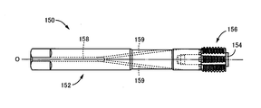
- FIGS. 17 and 18 are views showing a build-up tap 150 as an example of such a conventional indexable rotary tool.
- a tip 156 is detachably attached to a body 152 via a mounting screw 154.
- a large number of meshing teeth 160 and tooth grooves 162 are alternately provided radially on the opposing surfaces where the chips 156 face each other in the axial direction. It is fixed integrally impossible.
- FIG. 18 is a view showing the facing surface of the tip 156, in which the width dimension of the meshing tooth 160 is made larger than that of the tooth groove 162, and the body 152 side is configured in the opposite manner.
- the body 152 is provided with a fluid supply path 158 in the axial direction, and the fluid supply path 158 is branched in a Y shape into two or more branch paths 159 on the way. As the cooling fluid is discharged obliquely forward from the path 159, the rolling processed portion by the chip 156 is cooled.
- the number of parts is three. Therefore, it is difficult to obtain the centering accuracy between the body and the chip, and it becomes difficult to obtain sufficient strength because the sectional area of each part becomes small, and the connecting part may be suddenly damaged by the load torque, There was a problem that the tool life was shortened or varied. If the tool life varies in this way, it is difficult to predict the replacement time of the tool, and thus unattended operation cannot be performed.
- the cooling fluid can be supplied to the processing portion by the tip 156, but the fluid is obliquely separated from the position away from the tip 156 by the plurality of branch paths 159. Therefore, the fluid may be dispersed by centrifugal force or the like, and sufficient cooling performance may not be obtained, and the workpiece may be welded to the tip 156, leading to chipping of the rolling blade or breakage of the tap 150.
- the tool life was shortened and varied.
- Patent Document 2 a threaded shaft is integrally formed on a chip concentrically with an axis O, and is directly screwed into a threaded hole formed on the body, whereby an annular shoulder around the threaded shaft of the chip is attached to the tip of the body.
- a technique of pressing the surface and fixing it integrally since a separate mounting screw is not required and the body and the tip are composed of two parts, high centering accuracy is easily obtained, and the cross-sectional area of each part is increased to increase the strength.
- tensile stress acts on the screw shaft when the annular shoulder is pressed against the front end surface of the body, so that it is difficult to obtain high fastening strength.
- the raised tap is provided with a screw shaft and a screw hole in the torsion direction that are easily tightened during the rolling process of the female screw, so that it is easy to loosen at the time of backing, and if the fastening strength is low, the screw is loosened by drag torque. It is.
- the screw shaft provided integrally with the chip is screwed into the screw hole of the body and fastened, it is not possible to provide unevenness that meshes with each other on the mating surface (opposing surface). become.
- the present invention has been made against the background of the above circumstances, and the object thereof is to suppress variations in tool life in an indexable rotary tool in which a tip is detachably attached to the tip of a body by screw fastening. In addition, a high fastening strength is to be obtained.
- the first invention comprises (a) a shaft-shaped body and (b) a screw fastening so as to be concentrically attached to the front end of the body.
- the body is provided with a screw hole concentric with the axis O, and the tip is concentric with the axis O.
- the screw shaft provided on the screw hole is screwed into the screw hole, and the screw fastening is performed.
- the chip is integrally fixed to the body, and (e) the body is provided with a constraining hole concentric with the axis O, and the chip is constrained with the axis O.
- the axis O is the axis of the rotary tool in which the tip is attached to the body. Since the tip and the body are connected concentrically, the individual axis of the tip and the body is also the axis O. In this specification, these are expressed as the axis O without distinction.
- the outer diameter of the tip surface of the screw shaft that is brought into close contact with the bottom surface of the screw hole is within a range of 30% to 55% of the machining diameter by the tip. It is characterized by being. “ ⁇ ” includes the upper and lower limits of the numerical range.
- the nominal diameter of the screw hole and the screw shaft is within a range of 48% to 66% of a machining diameter by the insert.
- a fourth aspect of the invention is the indexable rotary tool according to any one of the first to third aspects of the invention, wherein (a) the fluid is supplied to the body so as to open vertically through the axis O to the bottom surface of the screw hole.
- the tip is provided with a center hole on the axis O from the tip end surface of the screw shaft, and a plurality of diameters from the outer periphery so as to communicate with the center hole.
- a cooling fluid is discharged from the fluid supply passage of the body through the center hole of the chip and a plurality of radial holes to the outer peripheral side of the chip.
- the tip end surface of the screw shaft is a convex tapered surface concentric with the axis O
- the bottom surface of the screw hole is It is a concave tapered surface that is concentric with the shaft center O and has the same taper angle as the tapered surface of the screw shaft, and these tapered surfaces are pressed so as to be in surface contact with each other.
- the screw shaft is screwed into the screw hole provided in the body, and the screw is fastened, and the tip is detachably attached to the body.
- the restriction portions of the chips are fitted into the restriction holes provided in the body, so that the bodies and the chips are positioned concentrically with the axis O.
- the tip of the screw shaft is pressed so that the screw shaft is brought into close contact with the bottom surface of the screw hole, and the chip is integrally fixed to the body, compressive stress acts on the screw shaft, and tension is applied.
- the chip can be fastened to the body with a higher fastening strength than that of Patent Document 2 where stress acts.
- a tool is pulled out by rotating backward (backing) after rolling of a female screw, such as a raised tap, even if drag torque is generated due to the elasticity of the rolled female screw, the drag torque causes the screw shaft to rotate. It is properly prevented that the screw is loosened and the tip is detached from the body.
- the strength of the body provided with the screw hole is appropriately set. While maintaining, high fastening strength can be obtained by frictional contact between the bottom surface of the screw hole and the tip surface of the screw shaft. Although it depends on the material of the body and the tip, if the outer diameter of the screw shaft tip surface is less than 30% of the machining diameter, the torque due to contact friction with the bottom surface of the screw hole will be reduced, making it difficult to obtain sufficient fastening strength. If it exceeds 55%, the thickness around the screw hole of the body becomes thin, and the body is easily damaged.
- the nominal diameter of the screw hole and the screw shaft is within the range of 48% to 66% of the machining diameter by the chip, the strength of the chip and the body is appropriately maintained, and the screw hole and screw are also maintained. High fastening strength can be obtained by screwing the shaft. Although it depends on the material of the body and the chip, if the nominal diameter of the screw is less than 48% of the machining diameter, the screw shaft becomes thin and the chip is likely to be damaged. The thickness becomes thin and the body is easily damaged.
- the cooling fluid is discharged from the fluid supply path provided in the body through the center hole of the chip and the plurality of radial holes to the outer peripheral side of the chip. It is possible to supply reliably, and excellent cooling performance can be obtained. Thereby, welding due to insufficient cooling is suppressed, and an excellent tool life can be stably obtained.
- both the tip surface of the screw shaft and the bottom surface of the screw hole are tapered surfaces concentric with the shaft center O and are pressed so as to be in surface contact with each other.
- the body and the tip are positioned with high accuracy by being concentric with the shaft center O in combination with the fitting of the restraining hole and the restraining portion.
- ⁇ durability test 3 which prepared five kinds of test goods from which a bottom contact surface diameter of a tip and a body differs, and performed rolling processing of a female screw, and investigated durability. It is the graph which showed the measurement result of durability (the number of processing holes) of Drawing 9 on the horizontal axis as a base surface diameter ratio. It is a graph which shows the result of ⁇ durability test 4 >> which performed the rolling process of the internal thread using the conventional product and this invention one by one, and investigated durability (the number of processing holes). It is a front view which shows another example of the chip
- FIG. 14 It is a front view which shows another example of the chip
- the indexable rotary tool of the present invention is suitably applied to a build-up tap for rolling a female thread, but is a cutting tap, drill, center drill, step drill, end mill, counterbore cutter, chamfering cutter, T slot It can be applied to various rotary tools such as carters. Die steel and high-speed tool steel are preferably used as the body, and cemented carbide is preferably used as the tip, but other tool materials and hard materials can also be adopted.
- the screw shaft provided on the chip and the screw hole of the screw hole provided on the body are tightened by the rotational resistance at the time of processing. It is desirable to set it to be selfish. For example, when machining is performed by rotating clockwise as viewed from the body side, the screw shaft and the screw hole may be right-handed.
- a predetermined fastening strength can be obtained by friction caused by surface contact between the tip surface and the bottom surface or friction of the screw shaft and screw hole. It is done.
- the tip surface of the screw shaft and the bottom surface of the screw hole are, for example, flat surfaces perpendicular to the axis O, but can also be tapered as in the fifth invention, or have a convex curved surface and a concave surface such as a partial spherical shape. Various modes are possible, such as a curved surface.
- the screw shaft and the screw thread shape of the screw hole may be a regular triangular screw, but a sawtooth buttress screw or the like may be employed.
- the restraint hole provided in the body is provided, for example, in the opening portion of the screw hole, and the restraint portion provided in the chip is provided in the proximal end portion of the screw shaft, but the restraint hole is provided on the bottom side of the screw hole and the restraint portion is provided. It is also possible to provide at the tip portion of the screw shaft.
- These restraining holes and restraining portions have, for example, a cylindrical shape with a constant diameter, and the fitting tolerance is, for example, about H6 / h6 grade. There may be a slight gap between them, or a slight interference fit.
- At least one of the outer peripheral surface of the restricting portion and the inner peripheral surface of the restricting hole can be a tapered surface, and can be positioned by being concentric with the axis O by the engagement of the tapered surface. In that case, it is configured such that the tip end surface of the screw shaft is allowed to be pressed against the bottom surface of the screw hole by screw fastening regardless of the engagement of the tapered surface due to elastic deformation of the restraint hole.
- the fluid supply path is provided so as to pass through the axis O of the body and open to the bottom surface of the screw hole, and the cooling fluid passes through the center hole of the chip and the plurality of radial holes to the outer peripheral side of the chip.
- a fluid supply path, a center hole, and a radial hole may be appropriately provided as necessary, and the cooling fluid can be directly supplied to the machining site by the tip by external oiling.
- various modes are possible, such as discharging from the body obliquely as in the conventional example of FIG.
- As the cooling fluid a cooling or lubricating oil is preferably used, but a gas such as cooling air can also be supplied.
- the oil agent can be supplied in a liquid state or in a mist state.
- FIG. 1 is a view showing an indexable raised tap (hereinafter simply referred to as a raised tap) 10 according to an embodiment of the present invention, and is a front view seen from a direction perpendicular to the axis O.
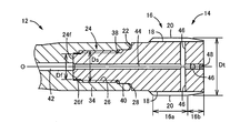
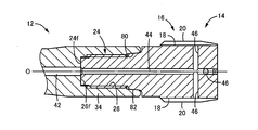
- FIG. FIG. 2 is an enlarged cross-sectional view of the tip portion including the tip 14 of the build-up tap 10
- FIG. 3 is a perspective view showing the tip 14 alone.
- the raised tap 10 includes a shaft-shaped body 12 and a tip 14 that is detachably attached to the tip of the body 12 by screw fastening. Thus, the thread rolling process is performed.
- the body 12 is made of die steel or high-speed tool steel, while the tip 14 is made of cemented carbide. A hard film is coated on the surface of the chip 14 as necessary.
- the tip 14 includes a male screw portion 16 having a male screw corresponding to a female screw to be processed provided on the outer peripheral surface.
- the male screw portion 16 includes a plurality of (eight in the embodiment) parallel to the axis O. ) Oil circulation groove 18 is provided, and the external thread is divided into a plurality of parts in the circumferential direction.
- the male thread portion 16 is provided so as to form a regular polygonal shape consisting of a side where the thread is curved outward, in this embodiment, a substantially octagonal cross section, and eight protrusions corresponding to the apex of the octagonal shape.
- the part functions as the rolling blade 20, and the female thread is rolled by cutting into the surface layer part of the pilot hole of the workpiece and causing plastic deformation.
- the oil circulation groove 18 is provided on each side of the octagon.
- the male thread portion 16 includes a complete mountain portion 16a in which the diameter dimension of the rolling blade 20 is substantially constant, and a biting portion 16b in which the diameter dimension gradually decreases toward the distal end side.
- the tip 14 of this embodiment is a rolling process of an M14 ⁇ 1.5 right-handed female screw, and the tip 14 is fed while being driven to rotate clockwise as viewed from the body 12 side.
- the internal thread is rolled by the rolling blade 20 after being screwed into the prepared hole of the workpiece.
- the diameter dimension Dt in FIG. 2 is a rolling blade diameter that is a processing diameter of the chip 14 and is 14 mm in this embodiment.
- a screw shaft 24 is erected concentrically with the shaft center O on the end face 22 of the male thread portion 16 on the complete mountain portion 16 a side, and is screwed into a screw hole 26 provided concentrically with the shaft center O on the body 12.
- the tip surface 24 f of the screw shaft 24 is pressed so as to be in close contact with the bottom surface 26 f of the screw hole 26, and the chip 14 is integrally attached to the body 12.
- Both the front end surface 24f and the bottom surface 26f are flat surfaces perpendicular to the axis O, and a predetermined fastening strength is obtained by friction caused by surface contact between them and friction caused by surface contact between the screw shaft 24 and the screw thread of the screw hole 26. Is obtained.
- a predetermined gap is formed between the tip end of the body 12, that is, the end face 28 on the opening side of the screw hole 26, and the end face 22 of the male thread portion 16 of the chip 14, and the screw shaft 24 and the screw hole
- the tip surface 24 f of the screw shaft 24 is reliably pressed against the bottom surface 26 f of the screw hole 26.
- the twist direction of the screw shaft 24 and the screw hole 26 is determined so as to be tightened by the rotational resistance at the time of rolling by the tip 14, and is rotated clockwise as viewed from the body 12 side.
- the screw shaft 24 and the screw hole 26 are also right-handed screws.
- the male thread portion 16 is provided with a flat tool locking portion 30 so that when the tip 14 is fastened to the body 12, the tool can be locked and torque can be applied.
- the bottom contact surface diameter Df at which the front end surface 24f of the screw shaft 24 and the bottom surface 26f of the screw hole 26 are in close contact, that is, the outer diameter of the front end surface 24f is in the range of 30% to 55% of the rolling blade diameter Dt. Specifically, it is within the range of 4.2 to 7.7 mm. Further, the nominal diameter of the screw of the screw shaft 24 and the screw hole 26, that is, the fastening screw diameter Ds is within the range of 48% to 66% of the rolling blade diameter Dt, specifically within the range of 6.72 to 9.24 mm. For example, M7 to M9 screws are provided. The fastening screw diameter Ds is larger than the bottom contact surface diameter Df.
- the body 12 has a stepped cylindrical shape with different diameter dimensions, and includes a rear-side shank 32, a leading-end-side connecting portion 34, and a small-diameter neck portion 36 therebetween concentrically and integrally.
- the screw hole 26 is provided in the connecting portion 34.
- a constraining hole 38 having a constant diameter larger than the fastening screw diameter Ds is provided in the opening portion of the screw hole 26 concentrically with the shaft center O, while the proximal end of the screw shaft 24 of the tip 14 is provided.
- a constraining portion 40 having a cylindrical outer peripheral surface having substantially the same diameter as that of the constraining hole 38 is provided concentrically with the shaft center O, and the constraining portion 40 is fitted into the constraining hole 38 as the screw is tightened.
- restraining holes 38 and restraining portions 40 are provided with fitting tolerances of, for example, about H6 / h6 grade, and are positioned concentrically with the axis O with high accuracy.
- the body 12 is provided with a fluid supply path 42 that passes through the shaft center O from the rear end on the shank 32 side and opens to the bottom surface 26f of the screw hole 26, while the tip 14 has a screw shaft.
- a center hole 44 is provided on the axis O from the front end surface 24 f of 24, and a plurality of radial holes 46 are provided from the outer periphery so as to communicate with the center hole 44.
- the plurality of radial holes 46 are provided, for example, so as to be orthogonal to the axis O so as to open to the groove bottom of the oil circulation groove 18 of the external thread portion 16, and correspond to the oil circulation groove 18. Eight are provided.
- the center hole 44 is provided so as to penetrate the chip 14 in the axial direction, and the opening on the distal end side is closed by a plug member 48.
- the cooling fluid flows through the center hole 44 and the plurality of radial holes 46 of the tip 14 to distribute the oil in the external thread portion 16.
- the roller 18 is discharged into the groove 18, and the rolling processed portion by the male screw portion 16 is appropriately cooled and lubricated.
- the cooling fluid is cooling air, a cooling oil agent, a lubricating oil agent, or the like.
- the screw shaft 24 is subjected to compressive stress.
- the tip 14 can be fastened to the body 12 with higher fastening strength than that of Patent Document 2 in which tensile stress acts.
- the tip 14 is made of a cemented carbide, the strength against tensile stress is lower than the compressive stress, and the fastening strength can be greatly improved by applying the compressive stress by screw fastening. it can.
- the bottom contact surface diameter Df which is the outer diameter of the tip surface 24f of the screw shaft 24 that is brought into close contact with the bottom surface 26f of the screw hole 26, is 30% to the machining diameter of the tip 14, that is, the rolling blade diameter Dt. Since it is within the range of 55%, high fastening strength is obtained by frictional contact between the bottom surface 26f of the screw hole 26 and the tip end surface 24f of the screw shaft 24 while maintaining the strength of the body 12 provided with the screw hole 26 appropriately. It is done. That is, when the bottom contact surface diameter Df is less than 30% of the rolling blade diameter Dt, the torque due to contact friction between the tip surface 24f and the bottom surface 26f becomes small, and it becomes difficult to obtain a sufficient fastening strength. When Df exceeds 55% of the rolling blade diameter Dt, the thickness around the screw hole 26 of the body 12 becomes thin, and the body 12 is easily damaged.
- the nominal diameter of the screw shaft 24 and the screw hole 26, that is, the fastening screw diameter Ds is within the range of 48% to 66% of the machining diameter by the tip 14, that is, the rolling blade diameter Dt. While maintaining the strength of the body 12 appropriately, high fastening strength can be obtained by screw fastening of the screw shaft 24 and the screw hole 26. That is, when the fastening screw diameter Ds is less than 48% of the rolling blade diameter Dt, the screw shaft 24 becomes thin and the tip 14 is easily damaged, and when the fastening screw diameter Ds exceeds 66% of the rolling blade diameter Dt. The thickness around the screw hole 26 of the body 12 becomes thin, and the body 12 is easily damaged.
- the cooling fluid is discharged from the fluid supply path 42 provided in the body 12 through the center hole 44 and the plurality of radial holes 46 of the chip 14 to the outer peripheral side of the chip 14.
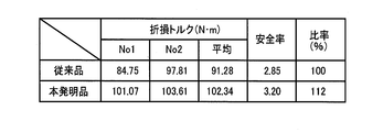
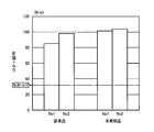
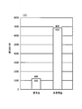
- FIG. 5 is a graph showing a comparison of the breaking torque of the four test products.
- the variation of the breaking torque of the two test products is as large as 13.06 (N ⁇ m) in the conventional product. It can be seen that the inventive product has a small variation of 2.54 (N ⁇ m), and a stable break strength can be obtained.
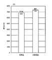
- FIG. 6 is a diagram showing the results of examining the durability by rolling a female screw under the following test conditions using the product of the embodiment of the present invention and the conventional product shown in FIGS. 17 and 18. It is.
- ⁇ Test conditions> ⁇ Nominal: M14 ⁇ 1.5 ⁇ Preliminary hole diameter: ⁇ 13.3 (through hole) ⁇ Hole depth: 30 mm ⁇ Rolled material: SCM440 (chrome molybdenum steel according to JIS) ⁇ Rolled material hardness: 30HRC Rolling speed: 30m / min Cutting fluid: Water-soluble
- the durability (the number of processed holes) is improved by about 7% compared to the conventional product.
- the conventional product has a life due to a rolling blade failure, so it is difficult to predict the life and unmanned operation is difficult. Life can be predicted from changes, etc., and unmanned operation is possible.
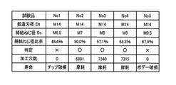
- FIG. 7 shows the results of investigating the durability of five types of test products (build-up taps) No. 1 to No. 5 with different fastening screw diameters Ds and rolling the female screw under the following test conditions.
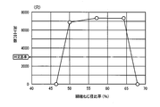
- FIG. 8 is a graph showing the durability (number of processed holes) of each test product with the fastening screw diameter ratio as the horizontal axis.
- the fastening screw diameters Ds of the five types of test products are M6.5, M7, M8, M9, and M9.5, respectively, and the “fastening screw diameter ratio” is (fastening screw diameter Ds / rolling blade diameter Dt).
- the fastening screw diameter Ds is preferably in the range of 48% to 66% of the rolling blade diameter Dt.
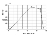
- FIG. 9 shows five types of test products (build-up taps) No. 1 to No. 5 with different bottom contact surface diameters Df, and rolls the female thread under the same test conditions as in ⁇ Durability Test 2>.
- FIG. 10 is a graph showing the durability (the number of processed holes) of each test product with the bottom surface area ratio as the horizontal axis.
- the bottom contact surface diameters Df of the five types of test products are 3 mm, 5.5 mm, 6.2 mm, 7.5 mm, and 8 mm, respectively, and the “bottom contact surface diameter ratio” is (bottom contact surface diameter Df / rolling blade diameter Dt). ).
- “ ⁇ ” (passed) and “x” (failed) are determined using 3000 holes as a determination criterion, and 3000 holes or more are “passed”.
- the bottom contact surface diameter Df is preferably in the range of 30% to 55% of the rolling blade diameter Dt.
- FIG. 11 is a diagram showing the results of investigating the durability by rolling a female thread under the following test conditions using the product of the embodiment of the present invention and the conventional product shown in FIGS. 17 and 18. It is.
- ⁇ Test conditions> ⁇ Nominal size: M14 ⁇ 1.5 ⁇ Preliminary hole diameter: ⁇ 13.3 (through hole) ⁇ Depth depth: 30 mm ⁇ Rolled material: S50C (carbon steel for machine structure according to JIS regulations; raw material) ⁇ Rolled Speed: 15m / min ⁇ Cutting fluid: Mist
- FIG. 12 is a front view of a chip 50 that can be used in place of the chip 14, and the thread shape of the screw shaft 52 is different from that of the chip 14. That is, the screw of the screw shaft 24 of the tip 14 is a normal triangular screw whose thread shape is a substantially equilateral triangle, but the screw of the screw shaft 52 of the tip 50 has a flank angle of the advance side flank (play side flank). This is a reverse buttress screw having a sawtooth shape that is smaller than the flank angle of the follower flank (pressure flank).
- the tip 60 of FIG. 13 can also be used in place of the tip 14, and the screw of the screw shaft 62 has a sawtooth shape like the screw shaft 52 of the tip 50, but is opposite to the screw shaft 52. This is a case of a positive buttress screw in which the flank angle of the follower flank (pressure flank) is smaller than the flank angle of the advance flank (play flank).
- the tip 70 of FIG. 14 can be used in place of the tip 14 as well, but the tip of the screw shaft 24 is provided with a tapered protrusion 72 concentrically with the axis O, as shown in FIG. As described above, a concave tapered bottom surface 74 having the same taper angle as that of the taper convex portion 72 is provided concentrically with the axis O at the bottom of the screw hole 26 of the body 12. Then, when the screw shaft 24 is screwed into the screw hole 26 and screwed, the taper outer peripheral surface 72f of the taper convex portion 72 is pressed so as to come into surface contact with the taper bottom surface 74 of the screw hole 26.
- the body 12 and the chip 70 are positioned with high accuracy by the concentricity with the axis O.
- the tapered outer peripheral surface 72 f corresponds to the tip end surface of the screw shaft 24, and the tapered bottom surface 74 corresponds to the bottom surface of the screw hole 26.
- FIG. 16 is a cross-sectional view corresponding to FIG. 2.
- the constraining hole 80 provided at the tip of the body 12 is a tapered surface having a diameter that increases toward the opening end. Concentric.
- the outer peripheral surface of the restraining portion 82 provided at the base end portion of the screw shaft 24 of the tip 14 is a tapered surface having a smaller diameter as the distance from the male screw portion 16 is equal to the taper angle of the restraining hole 80.
- the tapered outer peripheral surface of the restraining portion 82 is taper-fitted so as to come into surface contact with the tapered inner peripheral surface of the restraining hole 80, and the body 12.
- the tip 14 are positioned concentrically with the axis O.
- the portion of the body 12 in which the restraint hole 80 is provided that is, the tip end portion of the cylindrical connecting portion 34 is elastically deformed so as to expand toward the outer peripheral side by taper fitting with the restraint portion 82.
- the screw shaft 24 and the screw hole 26 are fastened so that the tip surface 24f of the screw shaft 24 is allowed to be pressed against the bottom surface 26f of the screw hole 26, and the friction between the tip surface 24f and the bottom surface 26f is allowed. It is the same as in the above embodiment that high fastening strength can be obtained by engagement. In this embodiment, friction due to surface contact between the restraint hole 80 and the restraint portion 82 also contributes to the fastening strength. Further, the constraining hole 80 and the constraining portion 82 that are taper-fitted in this way can also be applied to the embodiments shown in FIGS.
Landscapes
- Engineering & Computer Science (AREA)
- Mechanical Engineering (AREA)
- Milling Processes (AREA)
- Gripping On Spindles (AREA)
- Drilling Tools (AREA)
Priority Applications (5)
| Application Number | Priority Date | Filing Date | Title |
|---|---|---|---|
| PCT/JP2012/064598 WO2013183134A1 (ja) | 2012-06-06 | 2012-06-06 | インデキサブル式回転工具 |
| CN201280073754.9A CN104364042B (zh) | 2012-06-06 | 2012-06-06 | 可转位式挤压丝锥 |
| JP2014519755A JP5851603B2 (ja) | 2012-06-06 | 2012-06-06 | インデキサブル式盛上げタップ |
| EP12878634.0A EP2859978B1 (en) | 2012-06-06 | 2012-06-06 | Indexable rotating tool |
| US14/401,678 US9533363B2 (en) | 2012-06-06 | 2012-06-06 | Indexable thread forming tap |
Applications Claiming Priority (1)
| Application Number | Priority Date | Filing Date | Title |
|---|---|---|---|
| PCT/JP2012/064598 WO2013183134A1 (ja) | 2012-06-06 | 2012-06-06 | インデキサブル式回転工具 |
Publications (1)
| Publication Number | Publication Date |
|---|---|
| WO2013183134A1 true WO2013183134A1 (ja) | 2013-12-12 |
Family
ID=49711551
Family Applications (1)
| Application Number | Title | Priority Date | Filing Date |
|---|---|---|---|
| PCT/JP2012/064598 WO2013183134A1 (ja) | 2012-06-06 | 2012-06-06 | インデキサブル式回転工具 |
Country Status (5)
| Country | Link |
|---|---|
| US (1) | US9533363B2 (zh) |
| EP (1) | EP2859978B1 (zh) |
| JP (1) | JP5851603B2 (zh) |
| CN (1) | CN104364042B (zh) |
| WO (1) | WO2013183134A1 (zh) |
Families Citing this family (4)
| Publication number | Priority date | Publication date | Assignee | Title |
|---|---|---|---|---|
| EP3239055B1 (de) * | 2016-04-25 | 2019-01-30 | AIRBUS HELICOPTERS DEUTSCHLAND GmbH | Extrahiervorrichtung zum extrahieren eines trimmgewichts aus einem rotorblatt |
| CN111054951B (zh) * | 2019-12-06 | 2021-10-12 | 株洲钻石切削刀具股份有限公司 | 一种分体式旋转加工刀具 |
| DE102019133681A1 (de) | 2019-12-10 | 2021-06-10 | Gühring KG | Zerspanungswerkzeug und Verfahren zur Herstellung eines Zerspanungswerkzeuges |
| US11571221B2 (en) * | 2020-10-22 | 2023-02-07 | Spinal Simplicity, Llc | Combined bone tap and rasp |
Citations (6)
| Publication number | Priority date | Publication date | Assignee | Title |
|---|---|---|---|---|
| US1407335A (en) * | 1920-06-02 | 1922-02-21 | Charles B Reynolds | Pipe and tool joint |
| US5114286A (en) * | 1991-08-13 | 1992-05-19 | Calkins Donald W | Interchangeable tool alignment system |
| JPH10504767A (ja) * | 1994-08-29 | 1998-05-12 | サンドビック アクティエボラーグ | 着脱可能頂部を備えた軸工具 |
| US20040185948A1 (en) | 2001-07-25 | 2004-09-23 | Wolfgang Muller | Thread former or tap |
| JP4117131B2 (ja) | 2000-05-09 | 2008-07-16 | イスカーリミテッド | 工具の継ぎ手 |
| JP2010184339A (ja) * | 2009-02-13 | 2010-08-26 | Osg Corp | 流体供給孔付きタップ |
Family Cites Families (22)
| Publication number | Priority date | Publication date | Assignee | Title |
|---|---|---|---|---|
| CN85201412U (zh) * | 1985-04-13 | 1986-06-18 | 蒋尧夫 | 带有冷却液喷嘴的丝锥夹置装置 |
| JP2512876B2 (ja) | 1988-05-13 | 1996-07-03 | 株式会社ニコン | 実体顕微鏡の照明光学装置 |
| US5060740A (en) * | 1990-05-29 | 1991-10-29 | Sandvik Rock Tools, Inc. | Screw thread coupling |
| IL106697A (en) * | 1993-08-15 | 1996-10-16 | Iscar Ltd | A cutting board with an integral lining |
| JPH11285912A (ja) * | 1998-02-05 | 1999-10-19 | Toshiba Corp | エンドミル及びこれを用いた切削加工法 |
| EP0934788B1 (en) | 1998-02-05 | 2003-07-30 | Kabushiki Kaisha Toshiba | Endmill and cutting method |
| FR2787048B1 (fr) * | 1998-12-11 | 2001-01-26 | Pronic | Taraud a deformation de matiere par molettes filetees et rotatives |
| SE526762C2 (sv) * | 2002-06-17 | 2005-11-01 | Sandvik Intellectual Property | Han/hon-koppling uppvisande presspassning mellan delarna |
| SE528299C2 (sv) * | 2004-09-24 | 2006-10-17 | Seco Tools Ab | Skärspets och skärverktyg med hållardel utformad som stympad konisk gänga |
| JP2007030045A (ja) * | 2005-07-22 | 2007-02-08 | Max Co Ltd | 刃先交換型ドリル |
| US20110170980A1 (en) * | 2006-01-10 | 2011-07-14 | Mcgrade Stephen L | Ballistic Resistant Fastener |
| DE102006010651A1 (de) * | 2006-03-06 | 2007-09-20 | EMUGE-Werk Richard Glimpel GmbH & Co. KG Fabrik für Präzisionswerkzeuge | Kombinationswerkzeug mit Stirnaussparung |
| CN201089049Y (zh) * | 2007-08-17 | 2008-07-23 | 杨唯 | 硬质合金挤压丝锥 |
| JP5003363B2 (ja) * | 2007-09-06 | 2012-08-15 | マックス株式会社 | 穿孔工具 |
| IL191330A (en) * | 2008-05-11 | 2014-11-30 | Kennametal Inc | Component grinding tool with alternating blade |
| DE102008053772A1 (de) * | 2008-10-22 | 2010-04-29 | Komet Jel Precision Tools | Gewindeformer |
| JP2010099773A (ja) * | 2008-10-23 | 2010-05-06 | Yunitakku Kk | 深孔切削用ドリル |
| JP5362451B2 (ja) * | 2009-06-11 | 2013-12-11 | オーエスジー株式会社 | 加工ヘッド交換式回転工具、ホルダー、および加工ヘッド |
| CN202123294U (zh) * | 2011-05-13 | 2012-01-25 | 中国石油天然气集团公司 | 抽油杆接箍内螺纹卧式挤压丝锥 |
| AT13405U1 (de) | 2012-01-20 | 2013-12-15 | Ceratizit Austria Gmbh | Hartwerkstoff-gewindeverbindung |
| US9868162B2 (en) * | 2012-03-29 | 2018-01-16 | Hitachi Tool Engineering, Ltd. | Machining head, holder and exchangeable tip cutting tool |
| DE102013218884B4 (de) * | 2013-09-19 | 2015-05-21 | Kennametal Inc. | Spanendes Werkzeug |
-
2012
- 2012-06-06 US US14/401,678 patent/US9533363B2/en active Active
- 2012-06-06 WO PCT/JP2012/064598 patent/WO2013183134A1/ja active Application Filing
- 2012-06-06 CN CN201280073754.9A patent/CN104364042B/zh active Active
- 2012-06-06 JP JP2014519755A patent/JP5851603B2/ja active Active
- 2012-06-06 EP EP12878634.0A patent/EP2859978B1/en active Active
Patent Citations (6)
| Publication number | Priority date | Publication date | Assignee | Title |
|---|---|---|---|---|
| US1407335A (en) * | 1920-06-02 | 1922-02-21 | Charles B Reynolds | Pipe and tool joint |
| US5114286A (en) * | 1991-08-13 | 1992-05-19 | Calkins Donald W | Interchangeable tool alignment system |
| JPH10504767A (ja) * | 1994-08-29 | 1998-05-12 | サンドビック アクティエボラーグ | 着脱可能頂部を備えた軸工具 |
| JP4117131B2 (ja) | 2000-05-09 | 2008-07-16 | イスカーリミテッド | 工具の継ぎ手 |
| US20040185948A1 (en) | 2001-07-25 | 2004-09-23 | Wolfgang Muller | Thread former or tap |
| JP2010184339A (ja) * | 2009-02-13 | 2010-08-26 | Osg Corp | 流体供給孔付きタップ |
Non-Patent Citations (1)
| Title |
|---|
| See also references of EP2859978A4 |
Also Published As
| Publication number | Publication date |
|---|---|
| CN104364042A (zh) | 2015-02-18 |
| CN104364042B (zh) | 2016-09-28 |
| EP2859978A4 (en) | 2016-01-27 |
| JP5851603B2 (ja) | 2016-02-03 |
| JPWO2013183134A1 (ja) | 2016-01-21 |
| US20150133226A1 (en) | 2015-05-14 |
| US9533363B2 (en) | 2017-01-03 |
| EP2859978A1 (en) | 2015-04-15 |
| EP2859978B1 (en) | 2020-04-22 |
Similar Documents
| Publication | Publication Date | Title |
|---|---|---|
| JP5731643B2 (ja) | チップ着脱式回転工具 | |
| JP5362451B2 (ja) | 加工ヘッド交換式回転工具、ホルダー、および加工ヘッド | |
| US9623490B2 (en) | Three-bladed drill with cutting fluid supply hole | |
| US8425163B2 (en) | Thread forming tap | |
| JP5301647B2 (ja) | ドリル付きタップ、およびめねじ加工方法 | |
| WO2013183134A1 (ja) | インデキサブル式回転工具 | |
| CN103386513A (zh) | 铣削刀具 | |
| US20140056658A1 (en) | Cutting tool with removable head | |
| JPWO2009057192A1 (ja) | ねじ切りフライス | |
| JP5476267B2 (ja) | ドリル付きタップ | |
| JPWO2008102445A1 (ja) | 下穴加工具付きタップ | |
| WO2010049989A1 (ja) | スパイラルタップ | |
| WO2010103611A1 (ja) | スパイラルタップおよびその製造方法 | |
| US9737944B2 (en) | Thread-cutting tap | |
| US10814408B2 (en) | Replaceable-tip cutting tool main body and replaceable-tip cutting tool | |
| TWI722440B (zh) | 成形螺絲攻 | |
| JP5237659B2 (ja) | 切削タップ | |
| JP5475176B2 (ja) | 工具ホルダ | |
| WO2017094152A1 (ja) | 管用テーパねじ加工スパイラルタップ | |
| JPH061297Y2 (ja) | ねじ切削用タツプ | |
| JP5329504B2 (ja) | 盛上げタップ |
Legal Events
| Date | Code | Title | Description |
|---|---|---|---|
| 121 | Ep: the epo has been informed by wipo that ep was designated in this application |
Ref document number: 12878634 Country of ref document: EP Kind code of ref document: A1 |
|
| WWE | Wipo information: entry into national phase |
Ref document number: 14401678 Country of ref document: US |
|
| WWE | Wipo information: entry into national phase |
Ref document number: 2012878634 Country of ref document: EP |
|
| ENP | Entry into the national phase |
Ref document number: 2014519755 Country of ref document: JP Kind code of ref document: A |
|
| NENP | Non-entry into the national phase |
Ref country code: DE |