WO2013183134A1 - Indexable rotating tool - Google Patents

Indexable rotating tool Download PDF

Info

Publication number
WO2013183134A1
WO2013183134A1 PCT/JP2012/064598 JP2012064598W WO2013183134A1 WO 2013183134 A1 WO2013183134 A1 WO 2013183134A1 JP 2012064598 W JP2012064598 W JP 2012064598W WO 2013183134 A1 WO2013183134 A1 WO 2013183134A1
Authority
WO
WIPO (PCT)
Prior art keywords
screw
tip
hole
chip
shaft
Prior art date
Application number
PCT/JP2012/064598
Other languages
French (fr)
Japanese (ja)
Inventor
二朗 大沢
敬之 松下
顕太朗 乗松
格 伊東
Original Assignee
オーエスジー株式会社
Priority date (The priority date is an assumption and is not a legal conclusion. Google has not performed a legal analysis and makes no representation as to the accuracy of the date listed.)
Filing date
Publication date
Application filed by オーエスジー株式会社 filed Critical オーエスジー株式会社
Priority to CN201280073754.9A priority Critical patent/CN104364042B/en
Priority to PCT/JP2012/064598 priority patent/WO2013183134A1/en
Priority to JP2014519755A priority patent/JP5851603B2/en
Priority to EP12878634.0A priority patent/EP2859978B1/en
Priority to US14/401,678 priority patent/US9533363B2/en
Publication of WO2013183134A1 publication Critical patent/WO2013183134A1/en

Links

Images

Classifications

    • BPERFORMING OPERATIONS; TRANSPORTING
    • B23MACHINE TOOLS; METAL-WORKING NOT OTHERWISE PROVIDED FOR
    • B23GTHREAD CUTTING; WORKING OF SCREWS, BOLT HEADS, OR NUTS, IN CONJUNCTION THEREWITH
    • B23G1/00Thread cutting; Automatic machines specially designed therefor
    • B23G1/02Thread cutting; Automatic machines specially designed therefor on an external or internal cylindrical or conical surface, e.g. on recesses
    • B23G1/04Machines with one working-spindle
    • BPERFORMING OPERATIONS; TRANSPORTING
    • B23MACHINE TOOLS; METAL-WORKING NOT OTHERWISE PROVIDED FOR
    • B23BTURNING; BORING
    • B23B31/00Chucks; Expansion mandrels; Adaptations thereof for remote control
    • B23B31/005Cylindrical shanks of tools
    • BPERFORMING OPERATIONS; TRANSPORTING
    • B23MACHINE TOOLS; METAL-WORKING NOT OTHERWISE PROVIDED FOR
    • B23BTURNING; BORING
    • B23B31/00Chucks; Expansion mandrels; Adaptations thereof for remote control
    • B23B31/02Chucks
    • B23B31/10Chucks characterised by the retaining or gripping devices or their immediate operating means
    • B23B31/11Retention by threaded connection
    • BPERFORMING OPERATIONS; TRANSPORTING
    • B23MACHINE TOOLS; METAL-WORKING NOT OTHERWISE PROVIDED FOR
    • B23GTHREAD CUTTING; WORKING OF SCREWS, BOLT HEADS, OR NUTS, IN CONJUNCTION THEREWITH
    • B23G5/00Thread-cutting tools; Die-heads
    • B23G5/02Thread-cutting tools; Die-heads without means for adjustment
    • B23G5/06Taps
    • BPERFORMING OPERATIONS; TRANSPORTING
    • B23MACHINE TOOLS; METAL-WORKING NOT OTHERWISE PROVIDED FOR
    • B23GTHREAD CUTTING; WORKING OF SCREWS, BOLT HEADS, OR NUTS, IN CONJUNCTION THEREWITH
    • B23G7/00Forming thread by means of tools similar both in form and in manner of use to thread-cutting tools, but without removing any material
    • B23G7/02Tools for this purpose
    • BPERFORMING OPERATIONS; TRANSPORTING
    • B23MACHINE TOOLS; METAL-WORKING NOT OTHERWISE PROVIDED FOR
    • B23BTURNING; BORING
    • B23B2231/00Details of chucks, toolholder shanks or tool shanks
    • B23B2231/02Features of shanks of tools not relating to the operation performed by the tool
    • B23B2231/0204Connection of shanks to working elements of tools
    • BPERFORMING OPERATIONS; TRANSPORTING
    • B23MACHINE TOOLS; METAL-WORKING NOT OTHERWISE PROVIDED FOR
    • B23BTURNING; BORING
    • B23B2251/00Details of tools for drilling machines
    • B23B2251/02Connections between shanks and removable cutting heads
    • BPERFORMING OPERATIONS; TRANSPORTING
    • B23MACHINE TOOLS; METAL-WORKING NOT OTHERWISE PROVIDED FOR
    • B23BTURNING; BORING
    • B23B2260/00Details of constructional elements
    • B23B2260/138Screw threads
    • BPERFORMING OPERATIONS; TRANSPORTING
    • B23MACHINE TOOLS; METAL-WORKING NOT OTHERWISE PROVIDED FOR
    • B23BTURNING; BORING
    • B23B2260/00Details of constructional elements
    • B23B2260/138Screw threads
    • B23B2260/1388Screw threads with special profile not otherwise provided for
    • BPERFORMING OPERATIONS; TRANSPORTING
    • B23MACHINE TOOLS; METAL-WORKING NOT OTHERWISE PROVIDED FOR
    • B23GTHREAD CUTTING; WORKING OF SCREWS, BOLT HEADS, OR NUTS, IN CONJUNCTION THEREWITH
    • B23G2200/00Details of threading tools
    • B23G2200/02Tools in which the shank and the cutting part are made from different materials or from separate components
    • BPERFORMING OPERATIONS; TRANSPORTING
    • B23MACHINE TOOLS; METAL-WORKING NOT OTHERWISE PROVIDED FOR
    • B23GTHREAD CUTTING; WORKING OF SCREWS, BOLT HEADS, OR NUTS, IN CONJUNCTION THEREWITH
    • B23G2210/00Details of threads produced
    • B23G2210/04Internal threads
    • BPERFORMING OPERATIONS; TRANSPORTING
    • B23MACHINE TOOLS; METAL-WORKING NOT OTHERWISE PROVIDED FOR
    • B23GTHREAD CUTTING; WORKING OF SCREWS, BOLT HEADS, OR NUTS, IN CONJUNCTION THEREWITH
    • B23G2225/00Materials of threading tools, workpieces or other structural elements
    • B23G2225/28Hard metal, i.e. cemented carbides
    • BPERFORMING OPERATIONS; TRANSPORTING
    • B23MACHINE TOOLS; METAL-WORKING NOT OTHERWISE PROVIDED FOR
    • B23GTHREAD CUTTING; WORKING OF SCREWS, BOLT HEADS, OR NUTS, IN CONJUNCTION THEREWITH
    • B23G2240/00Details of equipment for threading other than threading tools, details of the threading process
    • B23G2240/12Means for cooling or lubrication

Abstract

By screwing a threaded shaft (24) provided on a tip (14) into a threaded hole (26) provided on a body (12), the tip (14) is detachably installed on the body (12). Additionally, a restraining part (40) of the tip (14) is fitted into a restraining hole (38) provided in the body (12) and the body (12) and the tip (14) are positioned to be concentric with the shaft center (O). As a result, a separate installation screw is unnecessary and the tool is configured from two parts, the body (12) and the tip (14). Therefore, high centering precision is easily obtained. Additionally, the cross-sectional areas of the respective parts increase and strength increases, variation in tool life is limited, and excellent tool life can be stably obtained. Moreover, because the surface (24f) of the tip of the threaded shaft (24) is pressed to adhere closely to the bottom surface (26f) of the threaded hole (26) and the tip (14) is fixed to the body (12) to form a unit, a compressive stress acts on the threaded shaft (24) and the tip (14) can be fastened to the body (12) with a higher fastening strength than when a tensile stress is in operation.

Description

インデキサブル式回転工具Indexable rotary tool
 本発明はインデキサブル式回転工具に係り、特に、ねじ締結によりボデーの先端部にチップが着脱可能に取り付けられるインデキサブル式回転工具の改良に関するものである。 The present invention relates to an indexable rotary tool, and more particularly to an improvement of an indexable rotary tool in which a tip is detachably attached to a front end portion of a body by screw fastening.
 (a) 軸形状のボデーと、(b) ねじ締結により前記ボデーの先端部に同心に着脱可能に取り付けられ、そのボデーと共に軸心Oまわりに回転駆動されることにより所定の加工を行うチップ、を有するインデキサブル式回転工具が提案されている。特許文献1に記載のタップはその一例で、ボデーに軸心Oと同心にねじ穴が設けられるとともに、チップには軸心Oと同心に取付穴が貫通して設けられ、取付ねじがチップの取付穴を貫通してボデーのねじ穴に螺合されることにより、チップがボデーに一体的に固定されるようになっている。また、ボデーとチップとの合わせ面にはそれぞれ凹凸が設けられ、それ等の凹凸が噛み合わさることにより、軸心Oまわりの相対回転が阻止されるようになっている。 (a) a shaft-shaped body, and (b) a tip that is detachably attached concentrically to the tip of the body by tightening a threaded screw, and performs predetermined processing by being rotationally driven around the shaft center O together with the body, An indexable rotary tool having the following has been proposed. The tap described in Patent Document 1 is one example, and the body is provided with a screw hole concentrically with the axis O, the tip is provided with a mounting hole concentrically with the axis O, and the mounting screw is the tip of the tip. The chip is fixed to the body integrally by passing through the mounting hole and screwing into the screw hole of the body. Further, the mating surfaces of the body and the chip are each provided with irregularities, and these irregularities mesh with each other so that relative rotation about the axis O is prevented.
 図17および図18は、このような従来のインデキサブル式回転工具の一例である盛上げタップ150を示す図で、ボデー152に取付ねじ154を介してチップ156が着脱可能に取り付けられるとともに、ボデー152およびチップ156が軸方向において互いに対面させられる対向面には、それぞれ図18に示すように多数の噛合い歯160および歯溝162が交互に放射状に設けられており、互いに噛み合わされることにより相対回転不能に一体的に固定される。図18はチップ156の対向面を示す図で、歯溝162に比較して噛合い歯160の幅寸法が大きくされており、ボデー152側はその逆に構成されている。ボデー152には、軸方向に流体供給路158が設けられているとともに、その流体供給路158は途中で2以上の複数の分岐路159にY字状に分岐させられており、それ等の分岐路159から冷却流体が斜め前方へ吐出されることにより、チップ156による転造加工部が冷却されるようになっている。 FIGS. 17 and 18 are views showing a build-up tap 150 as an example of such a conventional indexable rotary tool. A tip 156 is detachably attached to a body 152 via a mounting screw 154. As shown in FIG. 18, a large number of meshing teeth 160 and tooth grooves 162 are alternately provided radially on the opposing surfaces where the chips 156 face each other in the axial direction. It is fixed integrally impossible. FIG. 18 is a view showing the facing surface of the tip 156, in which the width dimension of the meshing tooth 160 is made larger than that of the tooth groove 162, and the body 152 side is configured in the opposite manner. The body 152 is provided with a fluid supply path 158 in the axial direction, and the fluid supply path 158 is branched in a Y shape into two or more branch paths 159 on the way. As the cooling fluid is discharged obliquely forward from the path 159, the rolling processed portion by the chip 156 is cooled.
米国特許出願公開第2004/0185948号公報US Patent Application Publication No. 2004/0185948 特許第4117131号公報Japanese Patent No. 4117131
 しかしながら、このように取付ねじがチップの取付穴を貫通してボデーのねじ穴に螺合されることにより、チップがボデーに一体的に固定されるインデキサブル式回転工具においては、部品数が3点であるためボデーとチップとの心出し精度が得られ難いとともに、各部品の断面積が小さくなって十分な強度が得られ難くなり、負荷トルクによって突発的に連結部が破損することがあり、工具寿命が短くなったりばらついたりする問題があった。そして、このように工具寿命がばらつくと、工具の交換時期を予測することが難しいため、無人運転を行うことができない。 However, in the indexable rotary tool in which the tip is fixed to the body integrally by passing through the mounting hole of the tip and screwing into the screw hole of the body in this way, the number of parts is three. Therefore, it is difficult to obtain the centering accuracy between the body and the chip, and it becomes difficult to obtain sufficient strength because the sectional area of each part becomes small, and the connecting part may be suddenly damaged by the load torque, There was a problem that the tool life was shortened or varied. If the tool life varies in this way, it is difficult to predict the replacement time of the tool, and thus unattended operation cannot be performed.
 また、前記図17、図18に記載のインデキサブル式盛上げタップ150の場合、チップ156による加工部位に対して冷却流体を供給できるものの、複数の分岐路159によりチップ156から離れた位置から斜めに流体を吐出するため、遠心力等により流体が分散して必ずしも十分な冷却性能が得られず、チップ156にワークが溶着して転造刃の刃欠けやタップ150の折損を生じることがあり、これも工具寿命が短くなったりばらついたりする一因となっていた。 In the case of the indexable rising tap 150 shown in FIGS. 17 and 18, the cooling fluid can be supplied to the processing portion by the tip 156, but the fluid is obliquely separated from the position away from the tip 156 by the plurality of branch paths 159. Therefore, the fluid may be dispersed by centrifugal force or the like, and sufficient cooling performance may not be obtained, and the workpiece may be welded to the tip 156, leading to chipping of the rolling blade or breakage of the tap 150. However, the tool life was shortened and varied.
 一方、特許文献2には、チップに軸心Oと同心にねじ軸を一体に設け、ボデーに設けられたねじ穴に直接螺合することにより、チップのねじ軸まわりの環状ショルダーをボデーの先端面に押圧して一体的に固定する技術が提案されている。この場合は、別体の取付ねじが不要となってボデーおよびチップの2部品で構成されるため、高い心出し精度が得られ易いとともに各部品の断面積が大きくなって強度が高くなり、工具寿命のばらつきが抑制されるが、環状ショルダーがボデーの先端面に押圧されることによりねじ軸に引張応力が作用するため、高い締結強度が得られ難い。特に、チップ材料として広く用いられている超硬合金の場合、圧縮応力に比較して引張応力に対する強度が低いため、十分な締結強度が得られない。このため、例えば盛上げタップのように、めねじの転造後に逆回転(バッキング)させて工具を抜き出す際にも、転造めねじの弾性により引き摺りトルクが生じる場合、ねじが緩んでボデーからチップが外れる可能性があった。すなわち、盛上げタップにおいては、めねじの転造加工時に締まり勝手となるねじれ方向のねじ軸およびねじ穴が設けられるため、バッキング時には緩み勝手となり、締結強度が低いと引き摺りトルクでねじが緩んでしまうのである。チップに一体に設けられたねじ軸をボデーのねじ穴に螺合して締結する場合、両者の合わせ面(対向面)に互いに噛み合う凹凸を設けることができないため、このようなねじの緩みが問題になる。 On the other hand, in Patent Document 2, a threaded shaft is integrally formed on a chip concentrically with an axis O, and is directly screwed into a threaded hole formed on the body, whereby an annular shoulder around the threaded shaft of the chip is attached to the tip of the body. There has been proposed a technique of pressing the surface and fixing it integrally. In this case, since a separate mounting screw is not required and the body and the tip are composed of two parts, high centering accuracy is easily obtained, and the cross-sectional area of each part is increased to increase the strength. Although the variation in life is suppressed, tensile stress acts on the screw shaft when the annular shoulder is pressed against the front end surface of the body, so that it is difficult to obtain high fastening strength. In particular, in the case of a cemented carbide widely used as a chip material, a sufficient fastening strength cannot be obtained because the strength against a tensile stress is lower than a compressive stress. For this reason, when pulling torque is generated due to the elasticity of the rolled female screw, for example, when the tool is pulled out by rotating backward (backing) after rolling the female screw, such as a raised tap, the screw loosens and inserts from the body. There was a possibility of coming off. In other words, the raised tap is provided with a screw shaft and a screw hole in the torsion direction that are easily tightened during the rolling process of the female screw, so that it is easy to loosen at the time of backing, and if the fastening strength is low, the screw is loosened by drag torque. It is. When the screw shaft provided integrally with the chip is screwed into the screw hole of the body and fastened, it is not possible to provide unevenness that meshes with each other on the mating surface (opposing surface). become.
 本発明は以上の事情を背景として為されたもので、その目的とするところは、ねじ締結によりボデーの先端部にチップが着脱可能に取り付けられるインデキサブル式回転工具において、工具寿命のばらつきを抑制するとともに高い締結強度が得られるようにすることにある。 The present invention has been made against the background of the above circumstances, and the object thereof is to suppress variations in tool life in an indexable rotary tool in which a tip is detachably attached to the tip of a body by screw fastening. In addition, a high fastening strength is to be obtained.
 かかる目的を達成するために、第1発明は、(a) 軸形状のボデーと、(b) ねじ締結により前記ボデーの先端部に同心に着脱可能に取り付けられ、そのボデーと共に軸心Oまわりに回転駆動されることにより所定の加工を行うチップ、を有するインデキサブル式回転工具において、(c) 前記ボデーには前記軸心Oと同心にねじ穴が設けられ、前記チップにその軸心Oと同心に設けられたねじ軸がそのねじ穴に螺合されることで前記ねじ締結が行われ、(d) そのねじ締結により前記ねじ軸の先端面が前記ねじ穴の底面に密着するように押圧されて、前記チップが前記ボデーに一体的に固定される一方、(e) 前記ボデーには前記軸心Oと同心に拘束穴が設けられ、前記チップにその軸心Oと同心に設けられた拘束部がその拘束穴内に嵌合されることにより、両者がその軸心Oと同心に位置決めされることを特徴とする。
 なお、上記軸心Oは、チップがボデーに取り付けられた回転工具の軸心であるが、それ等のチップおよびボデーは同心に連結されるため、チップおよびボデーの個々の軸心も軸心Oと見做すことができ、本明細書ではそれ等を区別することなく軸心Oと表現している。
In order to achieve such an object, the first invention comprises (a) a shaft-shaped body and (b) a screw fastening so as to be concentrically attached to the front end of the body. (C) The body is provided with a screw hole concentric with the axis O, and the tip is concentric with the axis O. The screw shaft provided on the screw hole is screwed into the screw hole, and the screw fastening is performed. (D) By the screw fastening, the tip surface of the screw shaft is pressed so as to be in close contact with the bottom surface of the screw hole. The chip is integrally fixed to the body, and (e) the body is provided with a constraining hole concentric with the axis O, and the chip is constrained with the axis O. Part is fitted into the restraint hole Both are characterized in that it is positioned on the axis O concentric.
The axis O is the axis of the rotary tool in which the tip is attached to the body. Since the tip and the body are connected concentrically, the individual axis of the tip and the body is also the axis O. In this specification, these are expressed as the axis O without distinction.
 第2発明は、第1発明のインデキサブル式回転工具において、前記ねじ穴の底面に密着させられる前記ねじ軸の先端面の外径は、前記チップによる加工径の30%~55%の範囲内であることを特徴とする。なお、「~」は数値範囲の上限および下限を含む。 According to a second aspect of the present invention, in the indexable rotary tool of the first aspect, the outer diameter of the tip surface of the screw shaft that is brought into close contact with the bottom surface of the screw hole is within a range of 30% to 55% of the machining diameter by the tip. It is characterized by being. “˜” includes the upper and lower limits of the numerical range.
 第3発明は、第1発明または第2発明のインデキサブル式回転工具において、前記ねじ穴および前記ねじ軸の呼び径は、前記チップによる加工径の48%~66%の範囲内であることを特徴とする。 According to a third aspect of the present invention, in the indexable rotary tool of the first or second aspect, the nominal diameter of the screw hole and the screw shaft is within a range of 48% to 66% of a machining diameter by the insert. And
 第4発明は、第1発明~第3発明の何れかのインデキサブル式回転工具において、(a) 前記ボデーには、前記軸心Oを縦通して前記ねじ穴の底面に開口するように流体供給路が設けられている一方、(b) 前記チップには、前記ねじ軸の先端面から前記軸心O上にセンター穴が設けられるとともに、そのセンター穴に連通するように外周部から複数の径方向穴が設けられており、(c) 前記ボデーの流体供給路から前記チップのセンター穴および複数の径方向穴を通って冷却流体がそのチップの外周側へ吐出されることを特徴とする。 A fourth aspect of the invention is the indexable rotary tool according to any one of the first to third aspects of the invention, wherein (a) the fluid is supplied to the body so as to open vertically through the axis O to the bottom surface of the screw hole. On the other hand, (b) the tip is provided with a center hole on the axis O from the tip end surface of the screw shaft, and a plurality of diameters from the outer periphery so as to communicate with the center hole. (C) A cooling fluid is discharged from the fluid supply passage of the body through the center hole of the chip and a plurality of radial holes to the outer peripheral side of the chip.
 第5発明は、第1発明~第4発明の何れかのインデキサブル式回転工具において、前記ねじ軸の先端面は前記軸心Oと同心の凸形状のテーパ面で、前記ねじ穴の底面はその軸心Oと同心で且つそのねじ軸のテーパ面とテーパ角が等しい凹形状のテーパ面であり、それ等のテーパ面が互いに面接触するように押圧されることを特徴とする。 According to a fifth aspect of the present invention, in the indexable rotary tool according to any one of the first to fourth aspects, the tip end surface of the screw shaft is a convex tapered surface concentric with the axis O, and the bottom surface of the screw hole is It is a concave tapered surface that is concentric with the shaft center O and has the same taper angle as the tapered surface of the screw shaft, and these tapered surfaces are pressed so as to be in surface contact with each other.
 このようなインデキサブル式回転工具においては、チップに設けられたねじ軸がボデーに設けられたねじ穴に螺合されることでねじ締結が行われ、このねじ締結でチップがボデーに着脱可能に取り付けられるとともに、ボデーに設けられた拘束穴内にチップの拘束部が嵌合されることで、それ等のボデーとチップとが軸心Oと同心に位置決めされる。これにより、前記特許文献2と同様に別体の取付ねじが不要となり、ボデーおよびチップの2部品で構成されるため、高い心出し精度が得られ易いとともに、各部品の断面積が大きくなって強度が高くなり、工具寿命のばらつきが抑制されて優れた工具寿命が安定して得られるようになる。 In such an indexable rotary tool, the screw shaft is screwed into the screw hole provided in the body, and the screw is fastened, and the tip is detachably attached to the body. At the same time, the restriction portions of the chips are fitted into the restriction holes provided in the body, so that the bodies and the chips are positioned concentrically with the axis O. This eliminates the need for a separate mounting screw as in Patent Document 2, and is composed of two parts, a body and a chip. Therefore, high centering accuracy is easily obtained, and the cross-sectional area of each part increases. The strength is increased, and variations in tool life are suppressed, and an excellent tool life can be stably obtained.
 また、ねじ締結によりねじ軸の先端面がねじ穴の底面に密着するように押圧されて、チップがボデーに一体的に固定されるため、ねじ軸には圧縮応力が作用するようになり、引張応力が作用する特許文献2に比較して高い締結強度でチップをボデーに締結できる。これにより、例えば盛上げタップのように、めねじの転造後に逆回転(バッキング)させて工具を抜き出す際に、転造めねじの弾性により引き摺りトルクが生じる場合でも、その引き摺りトルクでねじ軸のねじが緩んでチップがボデーから外れることが適切に防止される。 In addition, since the tip of the screw shaft is pressed so that the screw shaft is brought into close contact with the bottom surface of the screw hole, and the chip is integrally fixed to the body, compressive stress acts on the screw shaft, and tension is applied. The chip can be fastened to the body with a higher fastening strength than that of Patent Document 2 where stress acts. Thus, for example, when a tool is pulled out by rotating backward (backing) after rolling of a female screw, such as a raised tap, even if drag torque is generated due to the elasticity of the rolled female screw, the drag torque causes the screw shaft to rotate. It is properly prevented that the screw is loosened and the tip is detached from the body.
 第2発明では、ねじ穴の底面に密着させられるねじ軸の先端面の外径がチップによる加工径の30%~55%の範囲内であるため、ねじ穴が設けられるボデーの強度を適切に維持しつつ、ねじ穴の底面とねじ軸の先端面との摩擦接触により高い締結強度が得られる。ボデーおよびチップの材質によっても異なるが、ねじ軸の先端面の外径が加工径の30%未満になると、ねじ穴底面との接触摩擦によるトルクが小さくなって十分な締結強度が得られ難くなり、55%を超えると、ボデーのねじ穴の周囲の肉厚が薄くなってボデーが破損し易くなる。 In the second invention, since the outer diameter of the tip surface of the screw shaft that is brought into close contact with the bottom surface of the screw hole is within the range of 30% to 55% of the machining diameter by the chip, the strength of the body provided with the screw hole is appropriately set. While maintaining, high fastening strength can be obtained by frictional contact between the bottom surface of the screw hole and the tip surface of the screw shaft. Although it depends on the material of the body and the tip, if the outer diameter of the screw shaft tip surface is less than 30% of the machining diameter, the torque due to contact friction with the bottom surface of the screw hole will be reduced, making it difficult to obtain sufficient fastening strength. If it exceeds 55%, the thickness around the screw hole of the body becomes thin, and the body is easily damaged.
 第3発明では、ねじ穴およびねじ軸の呼び径がチップによる加工径の48%~66%の範囲内であるため、チップおよびボデーの強度を適切に維持しつつ、それ等のねじ穴およびねじ軸のねじ締結により高い締結強度が得られる。ボデーおよびチップの材質によっても異なるが、ねじの呼び径が加工径の48%未満になるとねじ軸が細くなってチップが破損し易くなり、66%を超えると、ボデーのねじ穴の周囲の肉厚が薄くなってボデーが破損し易くなる。 In the third invention, since the nominal diameter of the screw hole and the screw shaft is within the range of 48% to 66% of the machining diameter by the chip, the strength of the chip and the body is appropriately maintained, and the screw hole and screw are also maintained. High fastening strength can be obtained by screwing the shaft. Although it depends on the material of the body and the chip, if the nominal diameter of the screw is less than 48% of the machining diameter, the screw shaft becomes thin and the chip is likely to be damaged. The thickness becomes thin and the body is easily damaged.
 第4発明では、ボデーに設けられた流体供給路からチップのセンター穴および複数の径方向穴を通って冷却流体がそのチップの外周側へ吐出されるため、そのチップによる加工部位へ冷却流体を確実に供給することが可能で、優れた冷却性能が得られるようになる。これにより、冷却不足による溶着等が抑制され、優れた工具寿命が安定して得られるようになる。 In the fourth invention, the cooling fluid is discharged from the fluid supply path provided in the body through the center hole of the chip and the plurality of radial holes to the outer peripheral side of the chip. It is possible to supply reliably, and excellent cooling performance can be obtained. Thereby, welding due to insufficient cooling is suppressed, and an excellent tool life can be stably obtained.
 第5発明では、ねじ軸の先端面およびねじ穴の底面が共に軸心Oと同心のテーパ面で、互いに面接触するように押圧されることにより、それ等の接触摩擦で高い締結強度が得られるだけでなく軸心Oと同心に心出しされるため、前記拘束穴と拘束部との嵌合と相まって、ボデーとチップとが軸心Oと同心により高い精度で位置決めされる。 According to the fifth aspect of the present invention, both the tip surface of the screw shaft and the bottom surface of the screw hole are tapered surfaces concentric with the shaft center O and are pressed so as to be in surface contact with each other. In addition to being centered concentrically with the shaft center O, the body and the tip are positioned with high accuracy by being concentric with the shaft center O in combination with the fitting of the restraining hole and the restraining portion.
本発明の一実施例であるインデキサブル式盛上げタップを示す図で、軸心Oと直角方向から見た正面図である。It is a figure which shows the indexable type | formula increase tap which is one Example of this invention, and is the front view seen from the axial center O from the right angle. 図1のインデキサブル式盛上げタップのチップを含む先端部分の拡大断面図である。It is an expanded sectional view of the front-end | tip part containing the chip | tip of the indexable rising tap of FIG. 図1のインデキサブル式盛上げタップのチップを単独で示す斜視図である。It is a perspective view which shows independently the chip | tip of the indexable rising tap of FIG. 従来品および本発明品をそれぞれ2本用意して折損トルクを調べた《折損強度試験》の結果を説明する図である。It is a figure explaining the result of the << breakage strength test >> which prepared two each of the conventional goods and this invention, and investigated breakage torque. 図4の折損トルクの測定結果を比較して示したグラフである。It is the graph which showed the measurement result of the breaking torque of FIG. 4 in comparison. 従来品および本発明品を1本ずつ用いてめねじの転造加工を行い、耐久性(加工穴数)を調べた《耐久性試験1》の結果を示すグラフである。It is a graph which shows the result of << durability test 1 >> which carried out the rolling process of the internal thread using the conventional product and this invention one by one, and investigated durability (the number of processing holes). チップとボデーとの締結ねじ径が異なる5種類の試験品を用意し、めねじの転造加工を行って耐久性を調べた《耐久性試験2》の結果を説明する図である。It is a figure explaining the result of << durability test 2 >> which prepared five kinds of test goods from which a fastening screw diameter of a tip and a body differs, and performed endurance processing of a female screw. 図7の耐久性(加工穴数)の測定結果を、締結ねじ径比率を横軸として示したグラフである。It is the graph which showed the measurement result of durability (the number of processing holes) of Drawing 7 on the axis of a fastening screw diameter as a horizontal axis. チップとボデーとの底当て面径が異なる5種類の試験品を用意し、めねじの転造加工を行って耐久性を調べた《耐久性試験3》の結果を説明する図である。It is a figure explaining the result of << durability test 3 >> which prepared five kinds of test goods from which a bottom contact surface diameter of a tip and a body differs, and performed rolling processing of a female screw, and investigated durability. 図9の耐久性(加工穴数)の測定結果を、底当て面径比率を横軸として示したグラフである。It is the graph which showed the measurement result of durability (the number of processing holes) of Drawing 9 on the horizontal axis as a base surface diameter ratio. 従来品および本発明品を1本ずつ用いてめねじの転造加工を行い、耐久性(加工穴数)を調べた《耐久性試験4》の結果を示すグラフである。It is a graph which shows the result of << durability test 4 >> which performed the rolling process of the internal thread using the conventional product and this invention one by one, and investigated durability (the number of processing holes). 図1のインデキサブル式盛上げタップに好適に用いられるチップの別の例を示す正面図である。It is a front view which shows another example of the chip | tip suitably used for the indexable rising tap of FIG. 図1のインデキサブル式盛上げタップに好適に用いられるチップの更に別の例を示す正面図である。It is a front view which shows another example of the chip | tip suitably used for the indexable rise tap of FIG. 図1のインデキサブル式盛上げタップに好適に用いられるチップの更に別の例を示す正面図である。It is a front view which shows another example of the chip | tip suitably used for the indexable rise tap of FIG. 図14のチップが用いられたインデキサブル式盛上げタップの先端部分の断面図である。It is sectional drawing of the front-end | tip part of the indexable rising tap in which the chip | tip of FIG. 14 was used. 本発明の更に別の実施例を説明する図で、図2に対応する断面図である。It is a figure explaining another Example of this invention, and is sectional drawing corresponding to FIG. 従来のインデキサブル式盛上げタップの一例を示す図で、軸心と直角方向からみた正面図である。It is a figure which shows an example of the conventional indexable type enlarging tap, and is the front view seen from the direction orthogonal to an axial center. 図17のインデキサブル式盛上げタップのボデーおよびチップの対向面にそれぞれ設けられた噛合い歯を説明する図である。It is a figure explaining the meshing tooth respectively provided in the opposing surface of the body and chip | tip of the indexable riser tap of FIG.
 本発明のインデキサブル式回転工具は、めねじを転造加工する盛上げタップに好適に適用されるが、切削タップやドリル、センタードリル、段付きドリル、エンドミル、座ぐり用カッター、面取りカッター、Tスロットカーターなど、種々の回転工具に適用され得る。ボデーとしてはダイス鋼や高速度工具鋼が好適に用いられ、チップとしては超硬合金が好適に用いられるが、他の工具材料や硬質材料を採用することもできる。 The indexable rotary tool of the present invention is suitably applied to a build-up tap for rolling a female thread, but is a cutting tap, drill, center drill, step drill, end mill, counterbore cutter, chamfering cutter, T slot It can be applied to various rotary tools such as carters. Die steel and high-speed tool steel are preferably used as the body, and cemented carbide is preferably used as the tip, but other tool materials and hard materials can also be adopted.
 チップに設けられるねじ軸およびボデーに設けられるねじ穴のねじのねじれ方向は、例えば軸心Oまわりの一方へ回転駆動して加工を行うインデキサブル式回転工具の場合、その加工時の回転抵抗により締まり勝手となるように設定することが望ましい。例えばボデー側から見て右まわりに回転駆動して加工を行う場合、ねじ軸およびねじ穴も右ねじとすれば良い。 For example, in the case of an indexable rotary tool that is driven to rotate around one of the shaft centers O, the screw shaft provided on the chip and the screw hole of the screw hole provided on the body are tightened by the rotational resistance at the time of processing. It is desirable to set it to be selfish. For example, when machining is performed by rotating clockwise as viewed from the body side, the screw shaft and the screw hole may be right-handed.
 ねじ締結によりねじ軸の先端面がねじ穴の底面に密着するように押圧されることにより、その先端面と底面との面接触による摩擦やねじ軸およびねじ穴の摩擦で所定の締結強度が得られる。ねじ軸の先端面およびねじ穴の底面は、例えば軸心Oと直角な平坦面とされるが、第5発明のようにテーパ面とすることもできるし、部分球面状等の凸曲面および凹曲面とすることもできるなど、種々の態様が可能である。また、ねじ軸およびねじ穴のねじ山形状は、通常の三角ねじであっても良いが、鋸歯状のバットレスねじなどを採用することもできる。 When the screw shaft is pressed so that the tip surface of the screw shaft is in close contact with the bottom surface of the screw hole, a predetermined fastening strength can be obtained by friction caused by surface contact between the tip surface and the bottom surface or friction of the screw shaft and screw hole. It is done. The tip surface of the screw shaft and the bottom surface of the screw hole are, for example, flat surfaces perpendicular to the axis O, but can also be tapered as in the fifth invention, or have a convex curved surface and a concave surface such as a partial spherical shape. Various modes are possible, such as a curved surface. Further, the screw shaft and the screw thread shape of the screw hole may be a regular triangular screw, but a sawtooth buttress screw or the like may be employed.
 ボデーに設けられる拘束穴は、例えばねじ穴の開口部分に設けられ、チップに設けられる拘束部はねじ軸の基端部分に設けられるが、拘束穴をねじ穴の底部側に設けるとともに拘束部をねじ軸の先端部分に設けることも可能である。これ等の拘束穴および拘束部は、例えば径寸法が一定の円筒形状とされ、その嵌め合い公差は例えばH6/h6等級程度が適当である。それ等の間に僅かな隙間が生じたり、僅かに締まり嵌めになったりしても良い。また、拘束部の外周面および拘束穴の内周面の少なくとも一方をテーパ面とし、そのテーパ面の係合により軸心Oと同心に心出しして位置決めすることもできる。その場合は、拘束穴の弾性変形などで、テーパ面の係合に拘らずねじ締結によりねじ軸の先端面がねじ穴の底面に押圧されることが許容されるように構成される。 The restraint hole provided in the body is provided, for example, in the opening portion of the screw hole, and the restraint portion provided in the chip is provided in the proximal end portion of the screw shaft, but the restraint hole is provided on the bottom side of the screw hole and the restraint portion is provided. It is also possible to provide at the tip portion of the screw shaft. These restraining holes and restraining portions have, for example, a cylindrical shape with a constant diameter, and the fitting tolerance is, for example, about H6 / h6 grade. There may be a slight gap between them, or a slight interference fit. Further, at least one of the outer peripheral surface of the restricting portion and the inner peripheral surface of the restricting hole can be a tapered surface, and can be positioned by being concentric with the axis O by the engagement of the tapered surface. In that case, it is configured such that the tip end surface of the screw shaft is allowed to be pressed against the bottom surface of the screw hole by screw fastening regardless of the engagement of the tapered surface due to elastic deformation of the restraint hole.
 第4発明では、ボデーの軸心Oを縦通してねじ穴の底面に開口するように流体供給路が設けられ、チップのセンター穴および複数の径方向穴を通って冷却流体がチップの外周側へ吐出されるが、このような流体供給路やセンター穴、径方向穴は必要に応じて適宜設けられれば良く、外部給油でチップによる加工部位へ冷却流体を直接供給することもできる。また、図17の従来例のようにボデーから斜めに吐出するようにしても良いなど、種々の態様が可能である。冷却流体としては、冷却用や潤滑用の油剤が好適に用いられるが、冷却エアなどの気体を供給することもできる。油剤は、液体の状態で供給したりミストの状態で供給したりすることができる。 In the fourth aspect of the invention, the fluid supply path is provided so as to pass through the axis O of the body and open to the bottom surface of the screw hole, and the cooling fluid passes through the center hole of the chip and the plurality of radial holes to the outer peripheral side of the chip. However, such a fluid supply path, a center hole, and a radial hole may be appropriately provided as necessary, and the cooling fluid can be directly supplied to the machining site by the tip by external oiling. Further, various modes are possible, such as discharging from the body obliquely as in the conventional example of FIG. As the cooling fluid, a cooling or lubricating oil is preferably used, but a gas such as cooling air can also be supplied. The oil agent can be supplied in a liquid state or in a mist state.
 以下、本発明の実施例を、図面を参照しつつ詳細に説明する。
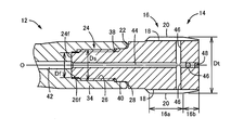
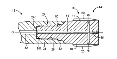
 図1は、本発明の一実施例であるインデキサブル式盛上げタップ(以下、単に盛上げタップという)10を示す図で、軸心Oと直角方向から見た正面図である。図2は、盛上げタップ10のチップ14を含む先端部分の拡大断面図で、図3はチップ14を単独で示す斜視図である。この盛上げタップ10は、軸形状のボデー12と、ねじ締結によりボデー12の先端部に同心に着脱可能に取り付けられるチップ14とを備えており、軸心Oまわりに回転駆動されることによりチップ14によってねじの転造加工が行われる。ボデー12はダイス鋼または高速度工具鋼にて構成されている一方、チップ14は超硬合金にて構成されている。チップ14の表面には必要に応じて硬質被膜がコーティングされる。
Hereinafter, embodiments of the present invention will be described in detail with reference to the drawings.
FIG. 1 is a view showing an indexable raised tap (hereinafter simply referred to as a raised tap) 10 according to an embodiment of the present invention, and is a front view seen from a direction perpendicular to the axis O. FIG. FIG. 2 is an enlarged cross-sectional view of the tip portion including the tip 14 of the build-up tap 10, and FIG. 3 is a perspective view showing the tip 14 alone. The raised tap 10 includes a shaft-shaped body 12 and a tip 14 that is detachably attached to the tip of the body 12 by screw fastening. Thus, the thread rolling process is performed. The body 12 is made of die steel or high-speed tool steel, while the tip 14 is made of cemented carbide. A hard film is coated on the surface of the chip 14 as necessary.
 チップ14は、加工すべきめねじに対応するおねじが外周面に設けられたおねじ部16を備えているとともに、そのおねじ部16には軸心Oと平行に複数(実施例では8本)の油流通溝18が設けられており、おねじが周方向において複数に分断されている。おねじ部16は、ねじ山が外側へ湾曲した辺からなる正多角形状、本実施例では略八角形状の断面を成すように設けられており、その八角形状の頂点に相当する8箇所の突出部が転造刃20として機能し、ワークの下穴の表層部に食い込んで塑性変形させることによりめねじを転造加工する。上記油流通溝18は八角形の各辺に設けられる。おねじ部16は、転造刃20の径寸法が略一定の完全山部16aと、先端側へ向かうに従って径寸法が徐々に小さくなる食付き部16bとを備えている。本実施例のチップ14は、M14×1.5の右ねじのめねじを転造加工するもので、ボデー12側から見て右まわりに回転駆動されつつリード送りされることにより、チップ14がワークの下穴内にねじ込まれて転造刃20によりめねじを転造加工する。図2の径寸法Dtは、チップ14の加工径である転造刃径で、本実施例では14mmである。 The tip 14 includes a male screw portion 16 having a male screw corresponding to a female screw to be processed provided on the outer peripheral surface. The male screw portion 16 includes a plurality of (eight in the embodiment) parallel to the axis O. ) Oil circulation groove 18 is provided, and the external thread is divided into a plurality of parts in the circumferential direction. The male thread portion 16 is provided so as to form a regular polygonal shape consisting of a side where the thread is curved outward, in this embodiment, a substantially octagonal cross section, and eight protrusions corresponding to the apex of the octagonal shape. The part functions as the rolling blade 20, and the female thread is rolled by cutting into the surface layer part of the pilot hole of the workpiece and causing plastic deformation. The oil circulation groove 18 is provided on each side of the octagon. The male thread portion 16 includes a complete mountain portion 16a in which the diameter dimension of the rolling blade 20 is substantially constant, and a biting portion 16b in which the diameter dimension gradually decreases toward the distal end side. The tip 14 of this embodiment is a rolling process of an M14 × 1.5 right-handed female screw, and the tip 14 is fed while being driven to rotate clockwise as viewed from the body 12 side. The internal thread is rolled by the rolling blade 20 after being screwed into the prepared hole of the workpiece. The diameter dimension Dt in FIG. 2 is a rolling blade diameter that is a processing diameter of the chip 14 and is 14 mm in this embodiment.
 上記おねじ部16の完全山部16a側の端面22には、軸心Oと同心にねじ軸24が立設されており、ボデー12に軸心Oと同心に設けられたねじ穴26に螺合されることにより、ねじ軸24の先端面24fがねじ穴26の底面26fに密着するように押圧され、チップ14がボデー12に一体的に取り付けられる。先端面24fおよび底面26fは何れも軸心Oと直角な平坦面で、それ等の面接触による摩擦と、ねじ軸24およびねじ穴26のねじ山の面接触による摩擦とにより、所定の締結強度が得られる。この締結状態において、ボデー12の先端すなわちねじ穴26の開口側の端面28と、チップ14のおねじ部16の端面22との間には、所定の隙間が形成され、ねじ軸24とねじ穴26とのねじ締結によりねじ軸24の先端面24fがねじ穴26の底面26fに確実に押圧されるようになっている。また、上記ねじ軸24およびねじ穴26のねじのねじれ方向は、チップ14による転造加工時の回転抵抗で締まり勝手となるように定められており、ボデー12側から見て右まわりに回転駆動して転造加工を行う本実施例の盛上げタップ10においては、ねじ軸24およびねじ穴26も右ねじである。おねじ部16には平坦な工具係止部30が設けられ、チップ14をボデー12に締結する際に工具を係止してトルクを付与できるようになっている。 A screw shaft 24 is erected concentrically with the shaft center O on the end face 22 of the male thread portion 16 on the complete mountain portion 16 a side, and is screwed into a screw hole 26 provided concentrically with the shaft center O on the body 12. As a result, the tip surface 24 f of the screw shaft 24 is pressed so as to be in close contact with the bottom surface 26 f of the screw hole 26, and the chip 14 is integrally attached to the body 12. Both the front end surface 24f and the bottom surface 26f are flat surfaces perpendicular to the axis O, and a predetermined fastening strength is obtained by friction caused by surface contact between them and friction caused by surface contact between the screw shaft 24 and the screw thread of the screw hole 26. Is obtained. In this fastened state, a predetermined gap is formed between the tip end of the body 12, that is, the end face 28 on the opening side of the screw hole 26, and the end face 22 of the male thread portion 16 of the chip 14, and the screw shaft 24 and the screw hole By screwing with the screw 26, the tip surface 24 f of the screw shaft 24 is reliably pressed against the bottom surface 26 f of the screw hole 26. Further, the twist direction of the screw shaft 24 and the screw hole 26 is determined so as to be tightened by the rotational resistance at the time of rolling by the tip 14, and is rotated clockwise as viewed from the body 12 side. In the build-up tap 10 of this embodiment that performs the rolling process, the screw shaft 24 and the screw hole 26 are also right-handed screws. The male thread portion 16 is provided with a flat tool locking portion 30 so that when the tip 14 is fastened to the body 12, the tool can be locked and torque can be applied.
 上記ねじ軸24の先端面24fとねじ穴26の底面26fとが密着させられる底当て面径Df、すなわち先端面24fの外径寸法は、転造刃径Dtの30%~55%の範囲内、具体的には4.2~7.7mmの範囲内とされている。また、ねじ軸24およびねじ穴26のねじの呼び径すなわち締結ねじ径Dsは、転造刃径Dtの48%~66%の範囲内、具体的には6.72~9.24mmの範囲内で、例えばM7~M9のねじが設けられる。この締結ねじ径Dsは、底当て面径Dfよりも大きな値となる。 The bottom contact surface diameter Df at which the front end surface 24f of the screw shaft 24 and the bottom surface 26f of the screw hole 26 are in close contact, that is, the outer diameter of the front end surface 24f is in the range of 30% to 55% of the rolling blade diameter Dt. Specifically, it is within the range of 4.2 to 7.7 mm. Further, the nominal diameter of the screw of the screw shaft 24 and the screw hole 26, that is, the fastening screw diameter Ds is within the range of 48% to 66% of the rolling blade diameter Dt, specifically within the range of 6.72 to 9.24 mm. For example, M7 to M9 screws are provided. The fastening screw diameter Ds is larger than the bottom contact surface diameter Df.
 ボデー12は、径寸法が異なる段付き円柱形状を成していて、後部側のシャンク32と、先端側の連結部34と、それ等の間の小径の首部36とを同心に一体に備えており、連結部34に前記ねじ穴26が設けられている。このねじ穴26の開口部分には、締結ねじ径Dsよりも大径の一定の径寸法の拘束穴38が軸心Oと同心に設けられている一方、前記チップ14のねじ軸24の基端部には、その拘束穴38と略同じ径寸法の円筒外周面を有する拘束部40が軸心Oと同心に設けられており、ねじ締結に伴って拘束部40が拘束穴38内に嵌合されることにより、ボデー12およびチップ14が軸心Oと同心に位置決めされる。これ等の拘束穴38および拘束部40は、例えばH6/h6等級程度の嵌め合い公差で設けられており、高い精度で軸心Oと同心に位置決めされる。 The body 12 has a stepped cylindrical shape with different diameter dimensions, and includes a rear-side shank 32, a leading-end-side connecting portion 34, and a small-diameter neck portion 36 therebetween concentrically and integrally. The screw hole 26 is provided in the connecting portion 34. A constraining hole 38 having a constant diameter larger than the fastening screw diameter Ds is provided in the opening portion of the screw hole 26 concentrically with the shaft center O, while the proximal end of the screw shaft 24 of the tip 14 is provided. A constraining portion 40 having a cylindrical outer peripheral surface having substantially the same diameter as that of the constraining hole 38 is provided concentrically with the shaft center O, and the constraining portion 40 is fitted into the constraining hole 38 as the screw is tightened. As a result, the body 12 and the tip 14 are positioned concentrically with the axis O. These restraining holes 38 and restraining portions 40 are provided with fitting tolerances of, for example, about H6 / h6 grade, and are positioned concentrically with the axis O with high accuracy.
 また、ボデー12には、シャンク32側の後端から軸心Oを縦通してねじ穴26の底面26fに開口するように流体供給路42が設けられている一方、チップ14には、ねじ軸24の先端面24fから軸心O上にセンター穴44が設けられるとともに、そのセンター穴44に連通するように外周部から複数の径方向穴46が設けられいる。複数の径方向穴46は、何れもおねじ部16の油流通溝18の溝底に開口するように、例えば軸心Oと直交するように設けられており、油流通溝18に対応して8本設けられる。また、センター穴44は、チップ14を軸方向に貫通して設けられており、先端側の開口部は栓部材48によって閉塞されている。これにより、ボデー12の後端から冷却流体が流体供給路42内に供給されると、その冷却流体はチップ14のセンター穴44および複数の径方向穴46を通っておねじ部16の油流通溝18内に吐出され、そのおねじ部16による転造加工部が適切に冷却、潤滑される。冷却流体は、冷却エアや冷却油剤、潤滑油剤などである。 The body 12 is provided with a fluid supply path 42 that passes through the shaft center O from the rear end on the shank 32 side and opens to the bottom surface 26f of the screw hole 26, while the tip 14 has a screw shaft. A center hole 44 is provided on the axis O from the front end surface 24 f of 24, and a plurality of radial holes 46 are provided from the outer periphery so as to communicate with the center hole 44. The plurality of radial holes 46 are provided, for example, so as to be orthogonal to the axis O so as to open to the groove bottom of the oil circulation groove 18 of the external thread portion 16, and correspond to the oil circulation groove 18. Eight are provided. The center hole 44 is provided so as to penetrate the chip 14 in the axial direction, and the opening on the distal end side is closed by a plug member 48. As a result, when the cooling fluid is supplied into the fluid supply path 42 from the rear end of the body 12, the cooling fluid flows through the center hole 44 and the plurality of radial holes 46 of the tip 14 to distribute the oil in the external thread portion 16. The roller 18 is discharged into the groove 18, and the rolling processed portion by the male screw portion 16 is appropriately cooled and lubricated. The cooling fluid is cooling air, a cooling oil agent, a lubricating oil agent, or the like.
 このような盛上げタップ10においては、チップ14に設けられたねじ軸24がボデー12に設けられたねじ穴26に螺合されることでねじ締結が行われ、このねじ締結でチップ14がボデー12に着脱可能に取り付けられるとともに、ボデー12に設けられた拘束穴38内にチップ14の拘束部40が嵌合されることで、それ等のボデー12とチップ14とが軸心Oと同心に位置決めされる。これにより、前記特許文献2と同様に別体の取付ねじが不要となり、ボデー12およびチップ14の2部品で構成されるため、高い心出し精度が得られ易いとともに、各部品の断面積が大きくなって強度が高くなり、工具寿命のばらつきが抑制されて優れた工具寿命が安定して得られるようになる。 In such a raised tap 10, the screw shaft 24 provided on the chip 14 is screwed into the screw hole 26 provided on the body 12, and the screw 14 is fastened. Are attached to the body 12, and the restraining portion 40 of the chip 14 is fitted into the restraining hole 38 provided in the body 12, so that the body 12 and the chip 14 are positioned concentrically with the axis O. Is done. This eliminates the need for a separate mounting screw as in Patent Document 2, and is composed of two parts, the body 12 and the chip 14, so that high centering accuracy is easily obtained and the cross-sectional area of each part is large. As a result, the strength is increased, and variations in tool life are suppressed, and an excellent tool life can be stably obtained.
 また、ねじ締結によりねじ軸24の先端面24fがねじ穴26の底面26fに密着するように押圧されて、チップ14がボデー12に一体的に固定されるため、ねじ軸24には圧縮応力が作用するようになり、引張応力が作用する特許文献2に比較して高い締結強度でチップ14をボデー12に締結できる。本実施例ではチップ14が超硬合金製であるため、圧縮応力に比較して引張応力に対する強度が低く、ねじ締結で圧縮応力が加えられるようにしたことにより締結強度を大幅に向上させることができる。これにより、めねじの転造加工後に盛上げタップ10を逆回転(バッキング)させて抜き出す際に、転造めねじの弾性により引き摺りトルクが生じる場合でも、その引き摺りトルクでねじ軸24のねじが緩んでチップ14がボデー12から外れることが適切に防止される。 Further, since the tip end surface 24f of the screw shaft 24 is pressed so as to be in close contact with the bottom surface 26f of the screw hole 26 by screw fastening, and the chip 14 is fixed integrally to the body 12, the screw shaft 24 is subjected to compressive stress. The tip 14 can be fastened to the body 12 with higher fastening strength than that of Patent Document 2 in which tensile stress acts. In this embodiment, since the tip 14 is made of a cemented carbide, the strength against tensile stress is lower than the compressive stress, and the fastening strength can be greatly improved by applying the compressive stress by screw fastening. it can. As a result, when pulling torque is generated due to the elasticity of the rolled female screw when the riser tap 10 is reversely rotated (backed) and pulled out after the female thread is rolled, the screw of the screw shaft 24 is loosened by the drag torque. Thus, the chip 14 is appropriately prevented from being detached from the body 12.
 また、本実施例ではねじ穴26の底面26fに密着させられるねじ軸24の先端面24fの外径である底当て面径Dfが、チップ14による加工径すなわち転造刃径Dtの30%~55%の範囲内であるため、ねじ穴26が設けられるボデー12の強度を適切に維持しつつ、ねじ穴26の底面26fとねじ軸24の先端面24fとの摩擦接触により高い締結強度が得られる。すなわち、底当て面径Dfが転造刃径Dtの30%未満になると、先端面24fと底面26fとの接触摩擦によるトルクが小さくなって十分な締結強度が得られ難くなり、底当て面径Dfが転造刃径Dtの55%を超えると、ボデー12のねじ穴26の周囲の肉厚が薄くなってボデー12が破損し易くなる。 In this embodiment, the bottom contact surface diameter Df, which is the outer diameter of the tip surface 24f of the screw shaft 24 that is brought into close contact with the bottom surface 26f of the screw hole 26, is 30% to the machining diameter of the tip 14, that is, the rolling blade diameter Dt. Since it is within the range of 55%, high fastening strength is obtained by frictional contact between the bottom surface 26f of the screw hole 26 and the tip end surface 24f of the screw shaft 24 while maintaining the strength of the body 12 provided with the screw hole 26 appropriately. It is done. That is, when the bottom contact surface diameter Df is less than 30% of the rolling blade diameter Dt, the torque due to contact friction between the tip surface 24f and the bottom surface 26f becomes small, and it becomes difficult to obtain a sufficient fastening strength. When Df exceeds 55% of the rolling blade diameter Dt, the thickness around the screw hole 26 of the body 12 becomes thin, and the body 12 is easily damaged.
 また、本実施例ではねじ軸24およびねじ穴26の呼び径すなわち締結ねじ径Dsが、チップ14による加工径すなわち転造刃径Dtの48%~66%の範囲内であるため、チップ14およびボデー12の強度を適切に維持しつつ、それ等のねじ軸24およびねじ穴26のねじ締結により高い締結強度が得られる。すなわち、締結ねじ径Dsが転造刃径Dtの48%未満になると、ねじ軸24が細くなってチップ14が破損し易くなり、締結ねじ径Dsが転造刃径Dtの66%を超えると、ボデー12のねじ穴26の周囲の肉厚が薄くなってボデー12が破損し易くなる。 In this embodiment, the nominal diameter of the screw shaft 24 and the screw hole 26, that is, the fastening screw diameter Ds is within the range of 48% to 66% of the machining diameter by the tip 14, that is, the rolling blade diameter Dt. While maintaining the strength of the body 12 appropriately, high fastening strength can be obtained by screw fastening of the screw shaft 24 and the screw hole 26. That is, when the fastening screw diameter Ds is less than 48% of the rolling blade diameter Dt, the screw shaft 24 becomes thin and the tip 14 is easily damaged, and when the fastening screw diameter Ds exceeds 66% of the rolling blade diameter Dt. The thickness around the screw hole 26 of the body 12 becomes thin, and the body 12 is easily damaged.
 また、本実施例ではボデー12に設けられた流体供給路42からチップ14のセンター穴44および複数の径方向穴46を通って冷却流体がチップ14の外周側へ吐出されるため、そのチップ14による転造加工部位へ冷却流体を確実に供給することが可能で、優れた冷却性能が得られるようになる。これにより、冷却不足による溶着等が抑制され、優れた工具寿命が安定して得られるようになる。 In this embodiment, the cooling fluid is discharged from the fluid supply path 42 provided in the body 12 through the center hole 44 and the plurality of radial holes 46 of the chip 14 to the outer peripheral side of the chip 14. Thus, it is possible to reliably supply the cooling fluid to the rolling processing site by means of which excellent cooling performance can be obtained. Thereby, welding due to insufficient cooling is suppressed, and an excellent tool life can be stably obtained.
《折損強度試験》
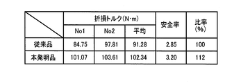
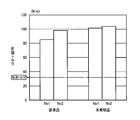
 ここで、上記実施例の本発明品および前記図17、図18に示す従来品を、それぞれNo1、No2の2本ずつ用意し、以下の試験条件で折損強度を調べたところ、図4および図5に示す結果が得られた。折損強度は、深さ10mmの下穴に対して盛上げタップが折損するまでねじ込み(底当て)、折損するまでの最大トルクを「折損トルク」として測定した。「安全率」は、折損トルクを転造トルクで割り算した値であり、転造トルクは通り穴の下穴に対して正常にめねじを転造加工した時のトルクで、今回の試験では32(N・m)である。
〈試験条件〉
 ・呼び:M14×1.5 ・下穴径:φ13.3(深さ10mmの止まり穴) ・被転造材料:SCM440(JISの規定によるクロムモリブデン鋼) ・被転造材硬さ:30HRC ・転造速度:6m/min ・加工機械:ラジアルボール盤 ・切削油剤:ミスト
<< Fracture strength test >>
Here, the present invention product of the above example and the conventional product shown in FIG. 17 and FIG. 18 were prepared as No1 and No2, respectively, and the breaking strength was examined under the following test conditions. The result shown in 5 was obtained. The breaking strength was measured by screwing (bottoming) until the raised tap broke into a pilot hole with a depth of 10 mm, and the maximum torque until breaking was measured as “breaking torque”. The “safety factor” is a value obtained by dividing the breakage torque by the rolling torque. The rolling torque is the torque when the internal thread is normally rolled to the pilot hole of the through hole. (N · m).
<Test conditions>
・ Nominal size: M14 × 1.5 ・ Preliminary hole diameter: φ13.3 (a blind hole with a depth of 10 mm) ・ Rolled material: SCM440 (chromium molybdenum steel according to JIS regulations) ・ Rolled material hardness: 30 HRC Rolling speed: 6m / min ・ Processing machine: Radial drilling machine ・ Cutting fluid: Mist
 図4の試験結果から明らかなように、従来品の平均折損トルクは91.28(N・m)で安全率は2.85であるのに対し、本発明品の平均折損トルクは102.34(N・m)で安全率は3.20であり、それ等の折損トルクや安全率が約12%向上した。図5は、4本の試験品の折損トルクを比較して示したグラフで、従来品は2本の試験品の折損トルクのばらつきが13.06(N・m)と大きいのに対し、本発明品は2.54(N・m)とばらつきが小さく、安定した折損強度が得られることが分かる。 As is apparent from the test results of FIG. 4, the average breakage torque of the conventional product is 91.28 (N · m) and the safety factor is 2.85, whereas the average breakage torque of the product of the present invention is 102.34. At (N · m), the safety factor was 3.20, and their breakage torque and safety factor were improved by about 12%. FIG. 5 is a graph showing a comparison of the breaking torque of the four test products. In contrast, the variation of the breaking torque of the two test products is as large as 13.06 (N · m) in the conventional product. It can be seen that the inventive product has a small variation of 2.54 (N · m), and a stable break strength can be obtained.
《耐久性試験1》
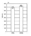
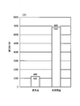
 図6は、前記実施例の本発明品および前記図17、図18に示す従来品を用いて、以下の試験条件でめねじの転造加工を行って耐久性を調べた結果を示した図である。
〈試験条件〉
 ・呼び:M14×1.5 ・下穴径:φ13.3(貫通穴) ・穴深さ:30mm  ・被転造材料:SCM440(JISの規定によるクロムモリブデン鋼) ・被転造材硬さ:30HRC ・転造速度:30m/min ・切削油剤:水溶性
<< Durability Test 1 >>
FIG. 6 is a diagram showing the results of examining the durability by rolling a female screw under the following test conditions using the product of the embodiment of the present invention and the conventional product shown in FIGS. 17 and 18. It is.
<Test conditions>
・ Nominal: M14 × 1.5 ・ Preliminary hole diameter: φ13.3 (through hole) ・ Hole depth: 30 mm ・ Rolled material: SCM440 (chrome molybdenum steel according to JIS) ・ Rolled material hardness: 30HRC Rolling speed: 30m / min Cutting fluid: Water-soluble
 図6から明らかなように、本発明品によれば従来品に比べて耐久性(加工穴数)が約7%向上した。また、従来品は転造刃の欠損により突発的に寿命になるため寿命予測が困難で無人運転が難しいのに対し、本発明品は転造刃の摩耗により寿命になるため、転造トルクの変化などから寿命を予測でき、無人運転化が可能である。 As is apparent from FIG. 6, according to the product of the present invention, the durability (the number of processed holes) is improved by about 7% compared to the conventional product. In addition, the conventional product has a life due to a rolling blade failure, so it is difficult to predict the life and unmanned operation is difficult. Life can be predicted from changes, etc., and unmanned operation is possible.
《耐久性試験2》
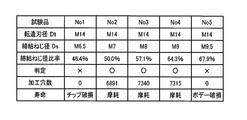
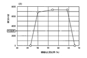
 図7は、前記締結ねじ径Dsが異なるNo1~No5の5種類の試験品(盛上げタップ)を用意し、以下の試験条件でめねじの転造加工を行って耐久性を調べた結果を説明する図で、図8は締結ねじ径比率を横軸として各試験品の耐久性(加工穴数)を示したグラフである。5種類の試験品の締結ねじ径DsはそれぞれM6.5、M7、M8、M9、M9.5で、「締結ねじ径比率」は(締結ねじ径Ds/転造刃径Dt)である。また、「判定」欄の○(合格)、×(不合格)は、3000穴を判定基準として判定したもので、3000穴以上が合格「○」である。
〈試験条件〉
 ・呼び:M14×1.5 ・下穴径:φ13.3(貫通穴) ・穴深さ:30mm  ・被転造材料:SCM440(JISの規定によるクロムモリブデン鋼) ・被転造材硬さ:30HRC ・転造速度:6m/min ・切削油剤:ミスト
<< Durability Test 2 >>
FIG. 7 shows the results of investigating the durability of five types of test products (build-up taps) No. 1 to No. 5 with different fastening screw diameters Ds and rolling the female screw under the following test conditions. FIG. 8 is a graph showing the durability (number of processed holes) of each test product with the fastening screw diameter ratio as the horizontal axis. The fastening screw diameters Ds of the five types of test products are M6.5, M7, M8, M9, and M9.5, respectively, and the “fastening screw diameter ratio” is (fastening screw diameter Ds / rolling blade diameter Dt). In the “determination” column, “◯” (passed) and “x” (failed) are determined using 3000 holes as a determination criterion, and 3000 holes or more are “passed”.
<Test conditions>
・ Nominal: M14 × 1.5 ・ Preliminary hole diameter: φ13.3 (through hole) ・ Hole depth: 30 mm ・ Rolled material: SCM440 (chrome molybdenum steel according to JIS) ・ Rolled material hardness: 30HRC ・ Rolling speed: 6m / min ・ Cutting fluid: Mist
 図7および図8に示す結果から明らかなように、締結ねじ径比率50%~64.3%の試験品No2~No4によれば、7000穴前後のめねじの転造加工が可能で優れた耐久性が得られた。これに対し、締結ねじ径比率が46.4%の試験品No1ではチップ14の破損で1穴も加工することができず、締結ねじ径比率が67.9%の試験品No5ではボデー12の破損で1穴も加工することができなかった。このことから、締結ねじ径Dsは、転造刃径Dtの48%~66%の範囲内が望ましい。 As is apparent from the results shown in FIGS. 7 and 8, according to the test products No. 2 to No. 4 having a fastening screw diameter ratio of 50% to 64.3%, it is possible to perform the rolling process of female screws around 7000 holes. Durability was obtained. On the other hand, in the test product No. 1 with the fastening screw diameter ratio of 46.4%, one hole cannot be processed due to the breakage of the chip 14, and in the test product No. 5 with the fastening screw diameter ratio of 67.9%, the body 12 One hole could not be processed due to breakage. For this reason, the fastening screw diameter Ds is preferably in the range of 48% to 66% of the rolling blade diameter Dt.
《耐久性試験3》
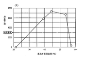
 図9は、底当て面径Dfが異なるNo1~No5の5種類の試験品(盛上げタップ)を用意し、《耐久性試験2》と同じ試験条件でめねじの転造加工を行って耐久性を調べた結果を説明する図で、図10は底当て面径比率を横軸として各試験品の耐久性(加工穴数)を示したグラフである。5種類の試験品の底当て面径Dfはそれぞれ3mm、5.5mm、6.2mm、7.5mm、8mmで、「底当て面径比率」は(底当て面径Df/転造刃径Dt)である。また、「判定」欄の○(合格)、×(不合格)は、3000穴を判定基準として判定したもので、3000穴以上が合格「○」である。
<< Durability Test 3 >>
Fig. 9 shows five types of test products (build-up taps) No. 1 to No. 5 with different bottom contact surface diameters Df, and rolls the female thread under the same test conditions as in <Durability Test 2>. FIG. 10 is a graph showing the durability (the number of processed holes) of each test product with the bottom surface area ratio as the horizontal axis. The bottom contact surface diameters Df of the five types of test products are 3 mm, 5.5 mm, 6.2 mm, 7.5 mm, and 8 mm, respectively, and the “bottom contact surface diameter ratio” is (bottom contact surface diameter Df / rolling blade diameter Dt). ). In the “determination” column, “◯” (passed) and “x” (failed) are determined using 3000 holes as a determination criterion, and 3000 holes or more are “passed”.
 図9および図10に示す結果から明らかなように、底当て面径比率が39.3%~53.6%の試験品No2~No4によれば、5000穴以上のめねじの転造加工が可能で優れた耐久性が得られた。これに対し、底当て面径比率が21.4%の試験品No1では、転造加工後のバッキング時に締結ねじが緩んでチップ14が外れ、1穴も加工することができなかった。また、底当て面径比率が57.1%の試験品No5では、328穴のめねじの転造加工でボデー12が破損した。このことから、底当て面径Dfは、転造刃径Dtの30%~55%の範囲内が望ましい。 As is apparent from the results shown in FIG. 9 and FIG. 10, according to the test products No. 2 to No. 4 having a bottom contact surface diameter ratio of 39.3% to 53.6%, it is possible to roll a female screw having 5000 holes or more. Possible and excellent durability was obtained. On the other hand, in the test product No. 1 having a bottom contact surface diameter ratio of 21.4%, the fastening screw was loosened at the time of backing after the rolling process, the tip 14 was detached, and one hole could not be processed. Further, in the test product No. 5 having a bottom contact surface diameter ratio of 57.1%, the body 12 was damaged by the rolling process of the female screw with 328 holes. Therefore, the bottom contact surface diameter Df is preferably in the range of 30% to 55% of the rolling blade diameter Dt.
《耐久性試験4》
 図11は、前記実施例の本発明品および前記図17、図18に示す従来品を用いて、以下の試験条件でめねじの転造加工を行って耐久性を調べた結果を示した図である。
〈試験条件〉
 ・呼び:M14×1.5 ・下穴径:φ13.3(貫通穴) ・穴深さ:30mm  ・被転造材料:S50C(JISの規定による機械構造用炭素鋼;生材) ・転造速度:15m/min ・切削油剤:ミスト
<< Durability Test 4 >>
FIG. 11 is a diagram showing the results of investigating the durability by rolling a female thread under the following test conditions using the product of the embodiment of the present invention and the conventional product shown in FIGS. 17 and 18. It is.
<Test conditions>
・ Nominal size: M14 × 1.5 ・ Preliminary hole diameter: φ13.3 (through hole) ・ Depth depth: 30 mm ・ Rolled material: S50C (carbon steel for machine structure according to JIS regulations; raw material) ・ Rolled Speed: 15m / min ・ Cutting fluid: Mist
 図11から明らかなように、本発明品によれば従来品に比べて5倍以上の耐久性(加工穴数)が得られた。これは、被転造材料が比較的溶着を生じ易い材料で、従来品はボデー152から斜めにミストを噴射しているため適切な潤滑性能が得られず、溶着により早期に転造刃が摩耗するのに対し、本発明品は、ボデー12に設けられた流体供給路42からチップ14のセンター穴44および複数の径方向穴46を通っておねじ部16による転造加工部位へ直接ミストが噴射されるため、優れた冷却性能が得られて溶着が適切に抑制されるためと考えられる。 As is clear from FIG. 11, according to the product of the present invention, durability (number of processed holes) more than 5 times that of the conventional product was obtained. This is a material in which the material to be rolled is relatively easily welded, and the conventional product cannot properly obtain lubrication performance because the mist is jetted obliquely from the body 152, and the rolling blade is worn early by welding. On the other hand, in the product of the present invention, mist is directly applied from the fluid supply path 42 provided on the body 12 to the rolling process portion by the male screw portion 16 through the center hole 44 and the plurality of radial holes 46 of the chip 14. Since it is injected, it is considered that excellent cooling performance is obtained and welding is appropriately suppressed.
 次に、本発明の他の実施例を説明する。なお、以下の実施例において前記実施例と実質的に共通する部分には同一の符号を付して詳しい説明を省略する。 Next, another embodiment of the present invention will be described. In the following embodiments, parts that are substantially the same as those in the above embodiments are denoted by the same reference numerals, and detailed description thereof is omitted.
 図12は、前記チップ14の代わりに用いることができるチップ50の正面図で、チップ14に比較してねじ軸52のねじ山形状が相違する。すなわち、チップ14のねじ軸24のねじは、ねじ山形状が略正三角形の通常の三角ねじであるが、チップ50のねじ軸52のねじは、進み側フランク(遊び側フランク)のフランク角が追い側フランク(圧力側フランク)のフランク角に比較して小さい鋸歯形状の逆バットレスねじである。 FIG. 12 is a front view of a chip 50 that can be used in place of the chip 14, and the thread shape of the screw shaft 52 is different from that of the chip 14. That is, the screw of the screw shaft 24 of the tip 14 is a normal triangular screw whose thread shape is a substantially equilateral triangle, but the screw of the screw shaft 52 of the tip 50 has a flank angle of the advance side flank (play side flank). This is a reverse buttress screw having a sawtooth shape that is smaller than the flank angle of the follower flank (pressure flank).
 図13のチップ60は、同じく前記チップ14の代わりに用いることができるもので、ねじ軸62のねじが上記チップ50のねじ軸52と同様に鋸歯形状であるが、ねじ軸52とは逆に追い側フランク(圧力側フランク)のフランク角が進み側フランク(遊び側フランク)のフランク角に比較して小さい正バットレスねじの場合である。 The tip 60 of FIG. 13 can also be used in place of the tip 14, and the screw of the screw shaft 62 has a sawtooth shape like the screw shaft 52 of the tip 50, but is opposite to the screw shaft 52. This is a case of a positive buttress screw in which the flank angle of the follower flank (pressure flank) is smaller than the flank angle of the advance flank (play flank).
 図14のチップ70は、同じく前記チップ14の代わりに用いることができるものであるが、ねじ軸24の先端に軸心Oと同心にテーパ凸部72が設けられている一方、図15に示すようにボデー12のねじ穴26の底部には、そのテーパ凸部72とテーパ角が等しい凹形状のテーパ底面74が軸心Oと同心に設けられている。そして、ねじ軸24がねじ穴26に螺合されてねじ締結されることにより、テーパ凸部72のテーパ外周面72fがねじ穴26のテーパ底面74に面接触するように押圧される。これにより、それ等のテーパ外周面72fとテーパ底面74との接触摩擦で高い締結強度が得られるだけでなく軸心Oと同心に心出しされるため、前記拘束穴38と拘束部40との嵌合と相まって、ボデー12とチップ70とが軸心Oと同心により高い精度で位置決めされる。テーパ外周面72fはねじ軸24の先端面に相当し、テーパ底面74はねじ穴26の底面に相当する。 The tip 70 of FIG. 14 can be used in place of the tip 14 as well, but the tip of the screw shaft 24 is provided with a tapered protrusion 72 concentrically with the axis O, as shown in FIG. As described above, a concave tapered bottom surface 74 having the same taper angle as that of the taper convex portion 72 is provided concentrically with the axis O at the bottom of the screw hole 26 of the body 12. Then, when the screw shaft 24 is screwed into the screw hole 26 and screwed, the taper outer peripheral surface 72f of the taper convex portion 72 is pressed so as to come into surface contact with the taper bottom surface 74 of the screw hole 26. As a result, not only high fastening strength is obtained by contact friction between the tapered outer peripheral surface 72f and the tapered bottom surface 74 but also centering is performed concentrically with the shaft center O. Coupled with the fitting, the body 12 and the chip 70 are positioned with high accuracy by the concentricity with the axis O. The tapered outer peripheral surface 72 f corresponds to the tip end surface of the screw shaft 24, and the tapered bottom surface 74 corresponds to the bottom surface of the screw hole 26.
 図16は、前記図2に対応する断面図で、この実施例ではボデー12の先端部に設けられた拘束穴80が開口端へ向かうに従って大径となるテーパ面とされて、軸心Oと同心に設けられている。また、チップ14のねじ軸24の基端部に設けられた拘束部82の外周面は、前記おねじ部16から離間するに従って小径となり且つ上記拘束穴80とテーパ角が等しいテーパ面とされて、軸心Oと同心に設けられている。そして、ねじ軸24がねじ穴26に螺合されてねじ締結される際に、拘束部82のテーパ外周面が拘束穴80のテーパ内周面に面接触するようにテーパ嵌合され、ボデー12とチップ14とが軸心Oと同心に心出しされて位置決めされる。この場合、ボデー12の拘束穴80が設けられた部分、すなわち円筒形状の連結部34の先端部分は、拘束部82とのテーパ嵌合で外周側へ拡径するように弾性変形させられ、これによりねじ軸24とねじ穴26とのねじ締結でねじ軸24の先端面24fがねじ穴26の底面26fに密着するように押圧されることが許容され、その先端面24fと底面26fとの摩擦係合で高い締結強度が得られることは前記実施例と同じである。なお、この実施例では、拘束穴80と拘束部82との間の面接触による摩擦も締結強度に寄与する。また、このようにテーパ嵌合する拘束穴80および拘束部82を、図12~図15の実施例に適用することもできる。 FIG. 16 is a cross-sectional view corresponding to FIG. 2. In this embodiment, the constraining hole 80 provided at the tip of the body 12 is a tapered surface having a diameter that increases toward the opening end. Concentric. Further, the outer peripheral surface of the restraining portion 82 provided at the base end portion of the screw shaft 24 of the tip 14 is a tapered surface having a smaller diameter as the distance from the male screw portion 16 is equal to the taper angle of the restraining hole 80. Are provided concentrically with the axis O. Then, when the screw shaft 24 is screwed into the screw hole 26 and screwed, the tapered outer peripheral surface of the restraining portion 82 is taper-fitted so as to come into surface contact with the tapered inner peripheral surface of the restraining hole 80, and the body 12. And the tip 14 are positioned concentrically with the axis O. In this case, the portion of the body 12 in which the restraint hole 80 is provided, that is, the tip end portion of the cylindrical connecting portion 34 is elastically deformed so as to expand toward the outer peripheral side by taper fitting with the restraint portion 82. Thus, the screw shaft 24 and the screw hole 26 are fastened so that the tip surface 24f of the screw shaft 24 is allowed to be pressed against the bottom surface 26f of the screw hole 26, and the friction between the tip surface 24f and the bottom surface 26f is allowed. It is the same as in the above embodiment that high fastening strength can be obtained by engagement. In this embodiment, friction due to surface contact between the restraint hole 80 and the restraint portion 82 also contributes to the fastening strength. Further, the constraining hole 80 and the constraining portion 82 that are taper-fitted in this way can also be applied to the embodiments shown in FIGS.
 以上、本発明の実施例を図面に基づいて詳細に説明したが、これ等はあくまでも一実施形態であり、本発明は当業者の知識に基づいて種々の変更,改良を加えた態様で実施することができる。 As mentioned above, although the Example of this invention was described in detail based on drawing, these are one embodiment to the last, and this invention is implemented in the aspect which added the various change and improvement based on the knowledge of those skilled in the art. be able to.
 10:インデキサブル式盛上げタップ(インデキサブル式回転工具)  12:ボデー  14、50、60、70:チップ  24、52、62:ねじ軸  24f:先端面  26:ねじ穴  26f:底面  38、80:拘束穴  40、82:拘束部  42:流体供給路  44:センター穴  46:径方向穴  72f:テーパ外周面(先端面、テーパ面)  74:テーパ底面(底面、テーパ面)  O:軸心  Dt:転造刃径(加工径)  Df:底当て面径(先端面の外径)  Ds:締結ねじ径(呼び径) 10: Indexable build-up tap (indexable rotary tool) 12: Body 14, 50, 60, 70: Tip 24, 52, 62: Screw shaft 24f: Tip surface 26: Screw hole 26f: Bottom 38, 80: Restraint hole 40 , 82: restraint part 42: fluid supply path 44: center hole 46: radial hole 72f: taper outer peripheral surface (tip surface, taper surface) 74: taper bottom surface (bottom surface, taper surface) O: shaft center Dt: rolling blade Diameter (working diameter) Df: Bottom contact surface diameter (outer diameter of the tip surface) Ds: Fastening screw diameter (nominal diameter)

Claims (5)

  1.  軸形状のボデーと、
     ねじ締結により前記ボデーの先端部に同心に着脱可能に取り付けられ、該ボデーと共に軸心Oまわりに回転駆動されることにより所定の加工を行うチップ、
     を有するインデキサブル式回転工具において、
     前記ボデーには前記軸心Oと同心にねじ穴が設けられ、前記チップに該軸心Oと同心に設けられたねじ軸が該ねじ穴に螺合されることで前記ねじ締結が行われ、
     該ねじ締結により前記ねじ軸の先端面が前記ねじ穴の底面に密着するように押圧されて、前記チップが前記ボデーに一体的に固定される一方、
     前記ボデーには前記軸心Oと同心に拘束穴が設けられ、前記チップに該軸心Oと同心に設けられた拘束部が該拘束穴内に嵌合されることにより、両者が該軸心Oと同心に位置決めされる
     ことを特徴とするインデキサブル式回転工具。
    A shaft-shaped body,
    A chip that is detachably attached concentrically to the tip of the body by screw fastening, and performs predetermined processing by being rotationally driven around the axis O together with the body,
    In an indexable rotary tool having
    The body is provided with a screw hole concentrically with the axis O, and the screw fastening is performed by screwing a screw shaft provided concentrically with the axis O to the chip into the screw hole,
    While the screw is pressed so that the tip surface of the screw shaft is in close contact with the bottom surface of the screw hole, the chip is integrally fixed to the body,
    The body is provided with a constraining hole concentrically with the axis O, and a constraining portion provided concentrically with the axis O on the chip is fitted into the constraining hole, so that both of the axes O Indexable rotary tool characterized by being positioned concentrically with the tool.
  2.  前記ねじ穴の底面に密着させられる前記ねじ軸の先端面の外径は、前記チップによる加工径の30%~55%の範囲内である
     ことを特徴とする請求項1に記載のインデキサブル式回転工具。
    The indexable rotation according to claim 1, wherein an outer diameter of a tip surface of the screw shaft that is brought into close contact with a bottom surface of the screw hole is in a range of 30% to 55% of a machining diameter by the chip. tool.
  3.  前記ねじ穴および前記ねじ軸の呼び径は、前記チップによる加工径の48%~66%の範囲内である
     ことを特徴とする請求項1または2に記載のインデキサブル式回転工具。
    The indexable rotary tool according to claim 1 or 2, wherein a nominal diameter of the screw hole and the screw shaft is within a range of 48% to 66% of a machining diameter by the tip.
  4.  前記ボデーには、前記軸心Oを縦通して前記ねじ穴の底面に開口するように流体供給路が設けられている一方、
     前記チップには、前記ねじ軸の先端面から前記軸心O上にセンター穴が設けられるとともに、該センター穴に連通するように外周部から複数の径方向穴が設けられており、
     前記ボデーの流体供給路から前記チップのセンター穴および複数の径方向穴を通って冷却流体が該チップの外周側へ吐出される
     ことを特徴とする請求項1~3の何れか1項に記載のインデキサブル式回転工具。
    While the body is provided with a fluid supply path so as to pass through the axis O and open to the bottom surface of the screw hole,
    The tip is provided with a center hole on the axis O from the tip surface of the screw shaft, and a plurality of radial holes are provided from the outer periphery so as to communicate with the center hole.
    The cooling fluid is discharged from the fluid supply path of the body through the center hole and a plurality of radial holes of the chip to the outer peripheral side of the chip. Indexable rotary tool.
  5.  前記ねじ軸の先端面は前記軸心Oと同心の凸形状のテーパ面で、前記ねじ穴の底面は該軸心Oと同心で且つ該ねじ軸のテーパ面とテーパ角が等しい凹形状のテーパ面であり、それ等のテーパ面が互いに面接触するように押圧される
     ことを特徴とする請求項1~4の何れか1項に記載のインデキサブル式回転工具。
    The tip surface of the screw shaft is a convex tapered surface concentric with the shaft center O, and the bottom surface of the screw hole is concentric with the shaft center O and has a concave taper with the same taper angle as the taper surface of the screw shaft. The indexable rotary tool according to any one of claims 1 to 4, wherein the indexable rotary tool is pressed so that the tapered surfaces thereof are in surface contact with each other.
PCT/JP2012/064598 2012-06-06 2012-06-06 Indexable rotating tool WO2013183134A1 (en)

Priority Applications (5)

Application Number Priority Date Filing Date Title
CN201280073754.9A CN104364042B (en) 2012-06-06 2012-06-06 Indexable formula thread forming tap
PCT/JP2012/064598 WO2013183134A1 (en) 2012-06-06 2012-06-06 Indexable rotating tool
JP2014519755A JP5851603B2 (en) 2012-06-06 2012-06-06 Indexable energizing tap
EP12878634.0A EP2859978B1 (en) 2012-06-06 2012-06-06 Indexable rotating tool
US14/401,678 US9533363B2 (en) 2012-06-06 2012-06-06 Indexable thread forming tap

Applications Claiming Priority (1)

Application Number Priority Date Filing Date Title
PCT/JP2012/064598 WO2013183134A1 (en) 2012-06-06 2012-06-06 Indexable rotating tool

Publications (1)

Publication Number Publication Date
WO2013183134A1 true WO2013183134A1 (en) 2013-12-12

Family

ID=49711551

Family Applications (1)

Application Number Title Priority Date Filing Date
PCT/JP2012/064598 WO2013183134A1 (en) 2012-06-06 2012-06-06 Indexable rotating tool

Country Status (5)

Country Link
US (1) US9533363B2 (en)
EP (1) EP2859978B1 (en)
JP (1) JP5851603B2 (en)
CN (1) CN104364042B (en)
WO (1) WO2013183134A1 (en)

Families Citing this family (4)

* Cited by examiner, † Cited by third party
Publication number Priority date Publication date Assignee Title
EP3239055B1 (en) * 2016-04-25 2019-01-30 AIRBUS HELICOPTERS DEUTSCHLAND GmbH Extracting device for extracting a trim weight from a rotor blade
CN111054951B (en) * 2019-12-06 2021-10-12 株洲钻石切削刀具股份有限公司 Split type rotary machining cutter
DE102019133681A1 (en) * 2019-12-10 2021-06-10 Gühring KG Cutting tool and method for producing a cutting tool
US11571221B2 (en) * 2020-10-22 2023-02-07 Spinal Simplicity, Llc Combined bone tap and rasp

Citations (6)

* Cited by examiner, † Cited by third party
Publication number Priority date Publication date Assignee Title
US1407335A (en) * 1920-06-02 1922-02-21 Charles B Reynolds Pipe and tool joint
US5114286A (en) * 1991-08-13 1992-05-19 Calkins Donald W Interchangeable tool alignment system
JPH10504767A (en) * 1994-08-29 1998-05-12 サンドビック アクティエボラーグ Shaft tool with removable top
US20040185948A1 (en) 2001-07-25 2004-09-23 Wolfgang Muller Thread former or tap
JP4117131B2 (en) 2000-05-09 2008-07-16 イスカーリミテッド Tool fitting
JP2010184339A (en) * 2009-02-13 2010-08-26 Osg Corp Tap with fluid supply hole

Family Cites Families (22)

* Cited by examiner, † Cited by third party
Publication number Priority date Publication date Assignee Title
CN85201412U (en) * 1985-04-13 1986-06-18 蒋尧夫 Tap clamper with coolant injectors
JP2512876B2 (en) 1988-05-13 1996-07-03 株式会社ニコン Illumination optics for stereo microscopes
US5060740A (en) * 1990-05-29 1991-10-29 Sandvik Rock Tools, Inc. Screw thread coupling
IL106697A (en) * 1993-08-15 1996-10-16 Iscar Ltd Cutting insert with integral clamping means
JPH11285912A (en) 1998-02-05 1999-10-19 Toshiba Corp End mill and cutting method using it
US6497540B1 (en) 1998-02-05 2002-12-24 Kabushiki Kaisha Toshiba Endmill and cutting method
FR2787048B1 (en) 1998-12-11 2001-01-26 Pronic THREAD WITH MATERIAL DEFORMATION THREADED AND ROTATING WHEELS
SE526762C2 (en) 2002-06-17 2005-11-01 Sandvik Intellectual Property He / she connection showing press fit between the parts
SE528299C2 (en) * 2004-09-24 2006-10-17 Seco Tools Ab Cutting tip and cutting tool with holder part designed as truncated conical thread
JP2007030045A (en) * 2005-07-22 2007-02-08 Max Co Ltd Knife edge replacement type drill
US20110170980A1 (en) * 2006-01-10 2011-07-14 Mcgrade Stephen L Ballistic Resistant Fastener
DE102006010651A1 (en) * 2006-03-06 2007-09-20 EMUGE-Werk Richard Glimpel GmbH & Co. KG Fabrik für Präzisionswerkzeuge Combination tool with front recess
CN201089049Y (en) * 2007-08-17 2008-07-23 杨唯 Hard alloy extrusion screw tap
JP5003363B2 (en) 2007-09-06 2012-08-15 マックス株式会社 Drilling tool
IL191330A (en) * 2008-05-11 2014-11-30 Kennametal Inc Milling tool assembly having a replaceable cutter
DE102008053772A1 (en) 2008-10-22 2010-04-29 Komet Jel Precision Tools thread former
JP2010099773A (en) 2008-10-23 2010-05-06 Yunitakku Kk Drill for cutting deep hole
JP5362451B2 (en) * 2009-06-11 2013-12-11 オーエスジー株式会社 Machining head replaceable rotary tool, holder, and machining head
CN202123294U (en) * 2011-05-13 2012-01-25 中国石油天然气集团公司 Horizontal extrusion screw tap for coupling internal thread of sucker rod
AT13405U1 (en) * 2012-01-20 2013-12-15 Ceratizit Austria Gmbh HART MATERIAL THREAD CONNECTION
EP2832481A4 (en) 2012-03-29 2015-08-12 Hitachi Tool Eng Machining head, holder and exchangeable tip cutting tool
DE102013218884B4 (en) 2013-09-19 2015-05-21 Kennametal Inc. Cutting tool

Patent Citations (6)

* Cited by examiner, † Cited by third party
Publication number Priority date Publication date Assignee Title
US1407335A (en) * 1920-06-02 1922-02-21 Charles B Reynolds Pipe and tool joint
US5114286A (en) * 1991-08-13 1992-05-19 Calkins Donald W Interchangeable tool alignment system
JPH10504767A (en) * 1994-08-29 1998-05-12 サンドビック アクティエボラーグ Shaft tool with removable top
JP4117131B2 (en) 2000-05-09 2008-07-16 イスカーリミテッド Tool fitting
US20040185948A1 (en) 2001-07-25 2004-09-23 Wolfgang Muller Thread former or tap
JP2010184339A (en) * 2009-02-13 2010-08-26 Osg Corp Tap with fluid supply hole

Non-Patent Citations (1)

* Cited by examiner, † Cited by third party
Title
See also references of EP2859978A4

Also Published As

Publication number Publication date
EP2859978A1 (en) 2015-04-15
US20150133226A1 (en) 2015-05-14
CN104364042B (en) 2016-09-28
EP2859978B1 (en) 2020-04-22
EP2859978A4 (en) 2016-01-27
CN104364042A (en) 2015-02-18
JP5851603B2 (en) 2016-02-03
US9533363B2 (en) 2017-01-03
JPWO2013183134A1 (en) 2016-01-21

Similar Documents

Publication Publication Date Title
JP5731643B2 (en) Insertable rotary tool
JP5362451B2 (en) Machining head replaceable rotary tool, holder, and machining head
US9623490B2 (en) Three-bladed drill with cutting fluid supply hole
US8425163B2 (en) Thread forming tap
JP5301647B2 (en) Drill tap and internal thread processing method
US20080089753A1 (en) Drill
WO2013183134A1 (en) Indexable rotating tool
CN103386513A (en) Milling tool
US20140056658A1 (en) Cutting tool with removable head
JP5476267B2 (en) Tap with drill
WO2010049989A1 (en) Spiral tap
WO2010103611A1 (en) Spiral tap and method for manufacturing the same
US9737944B2 (en) Thread-cutting tap
US10814408B2 (en) Replaceable-tip cutting tool main body and replaceable-tip cutting tool
TWI722440B (en) Forming screw tap
JP5237659B2 (en) Cutting tap
JP5475176B2 (en) Tool holder
WO2017094152A1 (en) Tapered pipe thread-machining spiral tap
JPH061297Y2 (en) Tap for screw cutting
JP5329504B2 (en) Raising tap

Legal Events

Date Code Title Description
121 Ep: the epo has been informed by wipo that ep was designated in this application

Ref document number: 12878634

Country of ref document: EP

Kind code of ref document: A1

WWE Wipo information: entry into national phase

Ref document number: 14401678

Country of ref document: US

WWE Wipo information: entry into national phase

Ref document number: 2012878634

Country of ref document: EP

ENP Entry into the national phase

Ref document number: 2014519755

Country of ref document: JP

Kind code of ref document: A

NENP Non-entry into the national phase

Ref country code: DE