JP5003363B2 - Drilling tool - Google Patents
Drilling tool Download PDFInfo
- Publication number
- JP5003363B2 JP5003363B2 JP2007231293A JP2007231293A JP5003363B2 JP 5003363 B2 JP5003363 B2 JP 5003363B2 JP 2007231293 A JP2007231293 A JP 2007231293A JP 2007231293 A JP2007231293 A JP 2007231293A JP 5003363 B2 JP5003363 B2 JP 5003363B2
- Authority
- JP
- Japan
- Prior art keywords
- shank
- shaft
- bit
- main body
- fitted
- Prior art date
- Legal status (The legal status is an assumption and is not a legal conclusion. Google has not performed a legal analysis and makes no representation as to the accuracy of the status listed.)
- Active
Links
Images


Classifications
-
- B—PERFORMING OPERATIONS; TRANSPORTING
- B23—MACHINE TOOLS; METAL-WORKING NOT OTHERWISE PROVIDED FOR
- B23B—TURNING; BORING
- B23B51/00—Tools for drilling machines
- B23B51/12—Adapters for drills or chucks; Tapered sleeves
-
- B—PERFORMING OPERATIONS; TRANSPORTING
- B23—MACHINE TOOLS; METAL-WORKING NOT OTHERWISE PROVIDED FOR
- B23B—TURNING; BORING
- B23B31/00—Chucks; Expansion mandrels; Adaptations thereof for remote control
- B23B31/02—Chucks
- B23B31/10—Chucks characterised by the retaining or gripping devices or their immediate operating means
- B23B31/11—Retention by threaded connection
-
- B—PERFORMING OPERATIONS; TRANSPORTING
- B23—MACHINE TOOLS; METAL-WORKING NOT OTHERWISE PROVIDED FOR
- B23B—TURNING; BORING
- B23B51/00—Tools for drilling machines
-
- B—PERFORMING OPERATIONS; TRANSPORTING
- B23—MACHINE TOOLS; METAL-WORKING NOT OTHERWISE PROVIDED FOR
- B23B—TURNING; BORING
- B23B2226/00—Materials of tools or workpieces not comprising a metal
- B23B2226/75—Stone, rock or concrete
-
- B—PERFORMING OPERATIONS; TRANSPORTING
- B23—MACHINE TOOLS; METAL-WORKING NOT OTHERWISE PROVIDED FOR
- B23B—TURNING; BORING
- B23B2251/00—Details of tools for drilling machines
- B23B2251/02—Connections between shanks and removable cutting heads
-
- B—PERFORMING OPERATIONS; TRANSPORTING
- B23—MACHINE TOOLS; METAL-WORKING NOT OTHERWISE PROVIDED FOR
- B23B—TURNING; BORING
- B23B2260/00—Details of constructional elements
- B23B2260/138—Screw threads
-
- B—PERFORMING OPERATIONS; TRANSPORTING
- B23—MACHINE TOOLS; METAL-WORKING NOT OTHERWISE PROVIDED FOR
- B23B—TURNING; BORING
- B23B2270/00—Details of turning, boring or drilling machines, processes or tools not otherwise provided for
- B23B2270/12—Centering of two components relative to one another
-
- B—PERFORMING OPERATIONS; TRANSPORTING
- B23—MACHINE TOOLS; METAL-WORKING NOT OTHERWISE PROVIDED FOR
- B23B—TURNING; BORING
- B23B2270/00—Details of turning, boring or drilling machines, processes or tools not otherwise provided for
- B23B2270/58—Oblique elements
-
- Y—GENERAL TAGGING OF NEW TECHNOLOGICAL DEVELOPMENTS; GENERAL TAGGING OF CROSS-SECTIONAL TECHNOLOGIES SPANNING OVER SEVERAL SECTIONS OF THE IPC; TECHNICAL SUBJECTS COVERED BY FORMER USPC CROSS-REFERENCE ART COLLECTIONS [XRACs] AND DIGESTS
- Y10—TECHNICAL SUBJECTS COVERED BY FORMER USPC
- Y10T—TECHNICAL SUBJECTS COVERED BY FORMER US CLASSIFICATION
- Y10T408/00—Cutting by use of rotating axially moving tool
- Y10T408/89—Tool or Tool with support
- Y10T408/907—Tool or Tool with support including detailed shank
-
- Y—GENERAL TAGGING OF NEW TECHNOLOGICAL DEVELOPMENTS; GENERAL TAGGING OF CROSS-SECTIONAL TECHNOLOGIES SPANNING OVER SEVERAL SECTIONS OF THE IPC; TECHNICAL SUBJECTS COVERED BY FORMER USPC CROSS-REFERENCE ART COLLECTIONS [XRACs] AND DIGESTS
- Y10—TECHNICAL SUBJECTS COVERED BY FORMER USPC
- Y10T—TECHNICAL SUBJECTS COVERED BY FORMER US CLASSIFICATION
- Y10T408/00—Cutting by use of rotating axially moving tool
- Y10T408/89—Tool or Tool with support
- Y10T408/909—Having peripherally spaced cutting edges
- Y10T408/9098—Having peripherally spaced cutting edges with means to retain Tool to support
- Y10T408/90993—Screw driven means
-
- Y—GENERAL TAGGING OF NEW TECHNOLOGICAL DEVELOPMENTS; GENERAL TAGGING OF CROSS-SECTIONAL TECHNOLOGIES SPANNING OVER SEVERAL SECTIONS OF THE IPC; TECHNICAL SUBJECTS COVERED BY FORMER USPC CROSS-REFERENCE ART COLLECTIONS [XRACs] AND DIGESTS
- Y10—TECHNICAL SUBJECTS COVERED BY FORMER USPC
- Y10T—TECHNICAL SUBJECTS COVERED BY FORMER US CLASSIFICATION
- Y10T408/00—Cutting by use of rotating axially moving tool
- Y10T408/94—Tool-support
- Y10T408/95—Tool-support with tool-retaining means
Description
本発明はコンクリート、モルタル、ブロック等に穿孔するための穿孔工具に関する。 The present invention relates to a drilling tool for drilling concrete, mortar, blocks and the like.
例えば、エアコンの屋外装置をコンクリートの壁に取り付ける場合、まずコンクリート壁に穿孔し、この下孔にアンカーを取り付け、アンカーに上記屋外装置をネジ止め固定することが行われる。 For example, when attaching an outdoor device of an air conditioner to a concrete wall, first, the concrete wall is drilled, an anchor is attached to the pilot hole, and the outdoor device is fixed to the anchor with a screw.
このような下孔を形成するための穿孔工具の先端にはシャンクが取り付けられ、シャンクの先端にはビットが設けられている。そして、ビットを回転させてその先端をコンクリートに押圧し、接触した部分を削りながら穿孔するものである。穿孔作業を繰り返すうちにビットは摩耗していくから、交換する必要がある。従前のビットはシャンクと一体に形成されていたが、シャンク部分は交換する必要はないので、現在はシャンクとビットとは別個に形成され、ビットをシャンクにネジ結合する構成とし(特許文献1参照)、ビットのみをシャンクに着脱できるようになっている。これにより、ビットが摩耗したときは、ビットのみを交換すればよく、シャンクは交換する必要がないので、交換のためのコストを低く抑えることができる。ただし、シャンクは工具本体の先端の本体軸に対してネジ結合により着脱自在となっており、不使用時には工具本体から取り外しておくのが普通である。 A shank is attached to the tip of the drilling tool for forming such a pilot hole, and a bit is provided at the tip of the shank. And a bit is rotated, the front-end | tip is pressed against concrete, and it drills, cutting the contact part. The bit wears out as the drilling process is repeated, so it needs to be replaced. The conventional bit is formed integrally with the shank, but the shank portion does not need to be replaced. Therefore, the shank and the bit are now formed separately, and the bit is screwed to the shank (see Patent Document 1). ), Only the bit can be attached to and detached from the shank. Thus, when the bit is worn, only the bit needs to be replaced, and the shank does not need to be replaced. Therefore, the cost for replacement can be kept low. However, the shank is detachably attached to the main body shaft at the tip of the tool body by screw connection, and is usually removed from the tool body when not in use.
ところで、このようにシャンクとビットとをネジ結合する構成では、シャンクの軸心とビットの軸心とのあいだにずれが生じる可能性がある。シャンクとビットの軸心が一致しないと、シャンクに対してビットは回転しながら円錐形を描くように振られるので、その先端は回転軸のまわりを旋回するように移動する。このため、穿孔効率が低下するだけでなく、下孔の孔径がビットの径よりも大きくなってしまい、アンカーの取り付け強度が損なわれてしまうという問題が発生する。なお、シャンクと工具本体の本体軸とのネジ結合の場合も、同じ問題が発生する。 By the way, in the configuration in which the shank and the bit are screw-coupled as described above, there is a possibility that a deviation occurs between the shank axis and the bit axis. If the shaft centers of the shank and the bit do not coincide with each other, the bit is swung in a conical shape while rotating with respect to the shank, so that the tip of the bit moves so as to swivel around the rotation axis. For this reason, not only does the drilling efficiency decrease, but the hole diameter of the pilot hole becomes larger than the diameter of the bit, which causes a problem that the attachment strength of the anchor is impaired. The same problem occurs in the case of screw connection between the shank and the main body shaft of the tool body.
そこで、シャンクとビットとの心合せはネジ部の螺合によって行われ、ネジ部の締め込みによって心合せができるようになっている。また、軸同士の直角度は、一方の突き当て面によって行われている。つまり、雄ネジ部の基部の座面に雌ネジ部の先端筒部の端面を突き当てることによって直角度を出すようにしている。シャンクと工具本体の本体軸とのネジ結合の場合の心合せと直角度も同様にして行っている。 Therefore, the centering of the shank and the bit is performed by screwing the screw part, and the centering can be performed by tightening the screw part. Further, the perpendicularity between the axes is set by one abutting surface. That is, the squareness is obtained by abutting the end surface of the distal end cylindrical portion of the female screw portion against the seating surface of the base portion of the male screw portion. The alignment and perpendicularity in the case of screw connection between the shank and the main body axis of the tool main body are performed in the same manner.
雄ネジ部と雌ネジ部との間にはわずかながら隙間があり、この隙間はネジを締めたり緩めたりする必要上避けることができない。ところが、シャンクとビットの間に隙間があると、シャンクの軸心とビットの軸心とのあいだにずれが生じる可能性がある。シャンクとビットの軸心が一致しないと、シャンクの軸心と回転軸とが一致している場合、ビットは回転しながら振られるので、その先端は回転軸のまわりを旋回するように移動する。したがって、穿孔効率が低下するだけでなく、下孔の孔径がビットの径よりも大きくなってしまい、アンカーの取り付け強度が損なわれてしまうという問題が発生する。なお、シャンクと工具本体の本体軸とのネジ結合の場合も、同じ問題が発生する。
しかしながら、軸同士をネジ結合する場合、雄ネジ部と雌ネジ部との間にはわずかながら隙間が必要となるので、心合せはネジの精度に左右されてしまう。また、軸同士の突き当て面は外部にあるため、傷などの外乱を受けやすい。このため、ネジの加工精度を確保しなければならず、また突き当て面の精度を維持しなければならないという問題があった。 However, when the shafts are screwed together, a slight gap is required between the male screw portion and the female screw portion, and therefore centering depends on the accuracy of the screw. In addition, since the abutting surfaces of the shafts are outside, they are susceptible to disturbances such as scratches. For this reason, there existed a problem that the processing precision of a screw had to be ensured and the accuracy of the abutting surface had to be maintained.
本発明は上記問題点を解消し、ネジの加工精度や突き当て面の精度維持することなく、シャンクとビット又はシャンクと工具本体との芯合わせを容易かつ確実に行うことができる穿孔工具を提供することをその課題とする。 The present invention eliminates the above problems and provides a drilling tool capable of easily and surely aligning a shank and a bit or a shank and a tool main body without maintaining the accuracy of screw processing and the abutment surface. The task is to do.
上記課題を解決するため、請求項1に係る発明は、工具本体の先端側に設けられた本体軸にシャンクを結合し、シャンクの先端側にビットを結合した穿孔工具において、上記ビット又は本体軸によって構成された連結体あるいは上記シャンクとビット又上記シャンクとをネジ結合させるとともに、シャンクと連結体のネジ部の近傍には、上記シャンクと連結体の中心を合わせる芯合せ用の案内部を、互いに軸方向に嵌合する嵌合部と被嵌合部とによって構成し、上記嵌合部と被嵌合部には、ネジ結合の深度を規制する突き当て部を形成するとともに、上記シャンク又はアダプタのビット結合側または上記本体軸側の端面に傾斜面を設けたことを特徴とする。
In order to solve the above-mentioned problems, the invention according to
請求項2に係る発明は、請求項1において、上記案内部を、上記シャンクと連結体のネジ部の先端側と基部側に設けたことを特徴とする。 According to a second aspect of the present invention, in the first aspect, the guide portion is provided on a distal end side and a base portion side of the thread portion of the shank and the coupling body .
請求項3に駆る発明は、請求項1又は2において、上記嵌合部と被嵌合部とをテーパ状に形成したことを特徴とする。 According to a third aspect of the present invention, in the first or second aspect, the fitting portion and the fitted portion are formed in a tapered shape .
請求項4に係る発明は、請求項1〜3のいずれかにおいて、上記案内部は、上記被嵌合部の雌ネジ部の中心に配置された軸状部と、上記嵌合部の雄ネジ部の先端に開口形成された円形断面の凹陥部とによって構成され、上記突き当て部は、上記被嵌合部の軸状部の先端と、上記嵌合部の凹陥部の底面とによって構成されたことを特徴とする。 According to a fourth aspect of the present invention, in any one of the first to third aspects, the guide portion includes a shaft-like portion disposed at the center of the female screw portion of the fitted portion, and a male screw of the fitting portion. And the abutting part is constituted by the tip of the shaft-like part of the fitted part and the bottom surface of the recessed part of the fitting part. It is characterized by that .
請求項1に係る発明によれば、シャンクと連結体とをネジで結合させるとともに、シャンクと連結体のネジ部の近傍には、シャンクと連結体の中心を合わせる芯合せ用の案内部を形成したから、連結体とシャンクのネジ部の加工精度が高くなくても、容易かつ確実に正確な芯合せが可能となる。したがって、従来のように突き当て端面で直角度を出す必要がない。 According to the first aspect of the present invention, the shank and the coupling body are coupled with the screw, and the centering guide portion for aligning the center of the shank and the coupling body is formed in the vicinity of the thread portion of the shank and the coupling body. Therefore, accurate alignment can be performed easily and surely even if the processing accuracy of the threaded portion of the coupling body and the shank is not high. Therefore, it is not necessary to make a squareness at the abutting end face as in the prior art.
また、上記案内部を、互いに軸方向に嵌合する嵌合部と被嵌合部とによって構成したから、雄ネジ部と雌ネジ部とのねじ込みも軸方向に進むので、嵌合部と被嵌合部との嵌合はねじ込みによって自動的に行われることになる。したがって、芯合せは容易に行われる。さらに、突き当て部によってビットがシャンクに対して突き当てられているので、ネジ結合の深度が規制され、ネジ締め込みが適正に保たれるので、シャンクに対してビットが相対回転してネジ込みが必要以上に進むことはない。In addition, since the guide portion is constituted by the fitting portion and the fitted portion that are fitted in the axial direction, the screwing of the male screw portion and the female screw portion also proceeds in the axial direction. The fitting with the fitting portion is automatically performed by screwing. Therefore, centering is easily performed. In addition, since the bit is abutted against the shank by the abutment part, the depth of screw coupling is regulated and the screw tightening is maintained properly, so the bit rotates relative to the shank and screwed in. Will not go further than necessary.
しかも、上記シャンク又はアダプタのビット結合側又は上記本体軸側の端面に傾斜面を設けてあるので、シャンクと連結体とを連結させたときに、上記端面の隙間のコンクリート研削粉を外部に排除させることができる。In addition, since an inclined surface is provided on the end face of the shank or adapter on the bit coupling side or the main body shaft side, when the shank and the connecting body are connected, the concrete grinding powder in the gap between the end faces is excluded to the outside. Can be made.
また、上記連結体をビットまたは本体軸またはアダプタによって構成したから、ビットとシャンクまたは本体軸とシャンクまたはアダプタとシャンクのネジ部の加工精度が高くなくても、容易かつ確実に正確な芯合せが可能となる。したがって、従来のように突き当て端面で直角度を出す必要がない。 In addition, since the connecting body is constituted by a bit, a body shaft, or an adapter, accurate and accurate alignment can be performed easily even if the processing accuracy of the thread portion of the bit and the shank or the body shaft and the shank or the adapter and the shank is not high. It becomes possible. Therefore, it is not necessary to make a squareness at the abutting end face as in the prior art.
請求項2に係る発明によれば、上記案内部を、上記シャンクと連結体のネジ部の先端側と基部側に設けたから、芯合せの精度が高くなる。 According to the invention which concerns on Claim 2, since the said guide part was provided in the front end side and base part side of the thread part of the said shank and a coupling body, the precision of centering becomes high.
請求項3に係る発明によれば、特に、案内部の嵌合部と被嵌合部とをテーパ状に形成したので、それぞれの中心をシャンクの軸心と一致するように形成することにより、芯合せが確実に行われる。According to the invention of
請求項4に係る発明によれば、案内部は、被嵌合部の雌ネジ部の中心に配置された軸状部と、嵌合部の雄ネジ部の先端に開口形成された円形断面の凹陥部とによって構成され、突き当て部は、被嵌合部の軸状部の先端と、嵌合部の凹陥部の底面とによって構成されているから、芯合せは容易に行われる。 According to the fourth aspect of the present invention, the guide portion has a shaft-like portion disposed at the center of the female screw portion of the fitted portion, and a circular cross-section formed open at the tip of the male screw portion of the fitting portion. Since it is comprised by the recessed part and the abutting part is comprised by the front-end | tip of the axial part of a to-be-fitted part, and the bottom face of the recessed part of a fitting part, centering is performed easily.
図1は本発明に係るドリルビットを使用する穿孔工具(コンクリートドリル)の縦断面図である。同図において符号1は工具本体を示す。工具本体1の内部には第1のモータ2と第2のモータ3が配置され、第1のモータ2の出力軸は減速歯車4を介して前端に設けられた本体軸5に噛合連結され、第2のモータ3は加振装置6に作動連結されている。工具本体1の後部にはグリップ7が一体に設けられ、グリップ7の端部には上記2つのモータ2、3に電力を供給する給電コード8が接続されている。
FIG. 1 is a longitudinal sectional view of a drilling tool (concrete drill) using a drill bit according to the present invention. In the figure,
上記本体軸5の先端にはドリルビット10が結合可能に設けられ、本体軸5の前端部には雄ネジ部11が、ドリルビット10の後端部には雌ネジ部12が形成されている。
A drill bit 10 is connectably provided at the tip of the
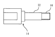
ドリルビット10は互いにネジ結合可能なシャンク13とビット14とから構成されている。シャンク13の前端には雌ネジ部15が形成されている。これに対し、ビット14は、図2(a)に示されるように、鉄製のベース17と、該ベース17上に固定されたダイヤモンド砥石体18とから構成されている。ベース17の砥石体18の反対側には雄ネジ部16が形成され、雄ネジ部16は図2(b)に示すように、シャンク13の後端の雌ネジ部15に螺合可能に形成されている。
The drill bit 10 is composed of a
なお、ダイヤモンド砥石体18は、一側に開口する凹欠部20を有する円柱状をなし、通常はメタルボンドの粒とダイヤモンド粒とを混合して焼結した焼結体である。上記凹欠部20は、主に穿孔時に削り取られたコンクリートの研削粉を外部に排除するための部分であり、通常は断面が扇形に形成されているが、必ずしも扇形である必要はない。
The
シャンク13に連結体の一例としてビット14を結合するときは、ビット14の雄ネジ部16をシャンク13の雌ネジ部15にねじ込めばよい。
When the
ところで、上記シャンク13とビット14のネジ部の近傍には、シャンク13とビット14の中心(回転中心)を合わせる芯合せ用の案内部と突き当て部が形成されている。
By the way, in the vicinity of the threaded portion of the
すなわち、図2(a)に示されるように、芯合せ用の案内部は、シャンク13の雌ネジ部15の前側に形成された円形断面の短筒状部21(被嵌合部)と、ビット14の雄ネジ部16の基部に形成された基軸部22(嵌合部)とによって構成されている。短筒状部21と基軸部22とは嵌合可能に形成されている。短筒状部21の中心はシャンク13の軸心と一致するように形成され、基軸部22の中心もビット14の軸心と一致するように形成されている。
That is, as shown in FIG. 2A, the centering guide portion includes a short cylindrical portion 21 (fitted portion) having a circular cross section formed on the front side of the
次に、シャンク13にビット14を結合するときは、同図(b)に示されるように、ビット14の雄ネジ部16と第2雄ネジ部16aをシャンク13の雌ネジ部15と第2雌ネジ部15aにねじ込む。ねじ込みが進むと、ビット14の基軸部22はシャンク13の短筒状部21に嵌合し、このとき芯合せが行われる。そして、最終的には、ビット14の雄ネジ部16と基軸部22との間の段差33が、シャンク13の雌ネジ部15と短筒状部21との間の段差32に突き当てられる。
Next, when the
以上のように、ビット14の基軸部22はシャンク13の短筒状部21に嵌合して芯合せが行われるから、ビット14の雄ネジ部16第2雄ネジ部16aと、シャンク13の雌ネジ部15及び第2雌ネジ部15aの加工精度が高くなくても、容易かつ確実に正確な芯合せが可能となる。したがって、従来のように直角度を出す必要がない。
As described above, since the
なお、突き当て部によってビット14がシャンク13に対して突き当てられているので、ネジ結合の深度が規制され、ネジ締め込みが適正に保たれるので、穿孔作業時にシャンク13に対してビット14が相対回転してネジ込みが必要以上に進むことはない。以下の形態においても同様である。
Since the
また、シャンク13のビット14結合側の端面に傾斜面51を設けることで、シャンク13とビット14を結合した時に同図(b)のようにシャンク13の傾斜面51とビット14のベース17に傾斜隙間52を形成させる。これは、穿孔時において、シャンク13とビット14の隙間にコンクリート研削粉が特に入り込みやすく、この隙間に詰まって付着しシャンク13とビット14が着脱できなくなる可能性があるが、傾斜隙間52の形状によって回転時に自然と外部へ排除させることができる。
Further, by providing an
次に、芯合せ用の案内部と突き当て部は上記形態に限定されない。次に、他の実施形態について説明する。 Next, the guide part and the abutting part for centering are not limited to the above-mentioned form. Next, another embodiment will be described.
図3(a)において、芯合せ用の案内部は2つの案内部によって構成されている。すなわち、第1案内部は、シャンク13の雌ネジ部15の前側に形成された円形断面の短筒状部21と、ビット14の雄ネジ部16の基部に形成された基軸部22とによって構成されている。短筒状部21と基軸部22とは嵌合可能に形成されている。短筒状部21の中心はシャンク13の軸心と、基軸部22の中心もビット14の軸心と同軸となるように形成されている。
In FIG. 3A, the centering guide part is constituted by two guide parts. That is, the first guide part is constituted by a short
第2案内部は、シャンク13の前端の雌ネジ部15の底面の中心に形成された円形断面の凹陥部25(被嵌合部)と、ビット14の雄ネジ部16の先端に形成された軸状部26(嵌合部)とによって構成されている。また、シャンク13の雌ネジ部15と短筒状部21と凹陥部25とはシャンク13の軸心と同軸上にあるように形成され、また、ビット14の雄ネジ部16と基軸部22と軸状部26とはビット14の軸心と同軸上にあるように形成されている。
The second guide part is formed at the front end of the
さらに、突き当て部はシャンク13の凹陥部25の底面27と、ビット14の軸状部26の先端28とによって構成されている。
Further, the abutting portion is constituted by the
次に、シャンク13にビット14を結合するときは、同図(b)に示されるように、ビット14の雄ネジ部16をシャンク13の雌ネジ部15にねじ込む。ねじ込みが進むと、ビット14の基軸部22はシャンク13の短筒状部21に嵌合する。同様に、ビット14の軸状部26はシャンク13の凹陥部25に嵌合する。このように、第1案内部と第2案内部とによって芯合せが行われる。そして、最終的には、第2雄ネジ部16aの先端28はシャンク13の凹陥部25の底面27に突き当てられる。
Next, when the
上記形態においては、ビット14は第1案内部と第2案内部とによって芯合せが行われるから、芯合せの精度はより高くなる。
In the above embodiment, since the
なお、案内部は図4に示すビット14の基軸部22とシャンクの短筒状部(図示せず)のように、長ければそれだけ芯合せの精度が高くなる。
In addition, as the guide portion is longer like the
次に、図5(a)も、芯合せ用の案内部を2つの案内部によって構成した形態であるが、第1案内部は、シャンク13の雌ネジ部15の前側に形成されたすり鉢形の短筒状部21aと、ビット14の雄ネジ部16の基部に形成されたテーパ状基軸部22aとによって構成されている。短筒状部21aと基軸部22aとは嵌合可能に形成されている。短筒状部21aの中心はシャンク13の軸心と、テーパ状基軸部22aの中心はビット14の軸心と同軸上にあるように形成されている。
Next, FIG. 5 (a) is also a form in which the guide part for centering is constituted by two guide parts. The first guide part is a mortar shape formed on the front side of the
また、第2案内部は、シャンク13の前端の雌ネジ部15の底面の中心に形成された円形断面の凹陥部25と、ビット14の雄ネジ部16の先端に形成された軸状部26とによって構成されている。上記凹陥部25と軸状部26とは嵌合可能に形成されている。凹陥部25の中心はシャンク13の軸心と、軸状部26の中心もビット14の軸心と同軸となるように形成されている。
Further, the second guide portion includes a recessed
さらに、突き当て部はシャンク13の短筒状部21aと、ビット14のテーパ状基軸部22aとによって構成されている。
Further, the abutting portion is constituted by the short
上記シャンク13にビット14を結合するときは、同図(b)に示されるように、ビット14の雄ネジ部16シャンク13の雌ネジ部15にねじ込む。ねじ込みが進むと、ビット14のテーパ状基軸部22aはシャンク13の短筒状部21aに嵌合する。同様に、ビット14の軸状部26はシャンク13の凹陥部25に嵌合する。このように、第1案内部と第2案内部とによって芯合せが行われる。そして、最終的には、テーパ状基軸部22aのテーパ面がシャンク13の短筒状部21aに嵌合して突き当てられる。
When the
上記形態においても、ビット14は第1案内部と第2案内部とによって芯合せが行われるから、芯合せの精度がより高くなる。
Also in the said form, since the
さらに、図6(a)も、芯合せ用の案内部を2つの案内部によって構成した形態であり、第1案内部は、シャンク13の雌ネジ部15の前側に形成された短筒状部21と、ビット14の雄ネジ部16の基部に形成された基軸部22とによって構成されている。短筒状部21と基軸部22とは嵌合可能に形成されている。短筒状部21の中心はシャンク13の軸心と、基軸部22の中心はビット14の軸心と同軸となるように形成されている。
Further, FIG. 6A is also a form in which the centering guide portion is constituted by two guide portions, and the first guide portion is a short cylindrical portion formed on the front side of the
また、第2案内部は、シャンク13の前端の雌ネジ部15の底面の中心に形成されたすり鉢形の凹陥部25aと、ビット14の雄ネジ部16の先端に形成されたテーパ状軸状部26aとによって構成されている。上記凹陥部25aとテーパ状軸状部26aとは嵌合可能に形成されている。凹陥部25aの中心はシャンク13の軸心と一致するように形成され、軸状部26aの中心もビット14の軸心と一致するように形成されている。
Further, the second guide portion is a tapered shaft-like shape formed at the tip of the mortar-shaped recessed
さらに、突き当て部はシャンク13の凹陥部25aと、ビット14のテーパ状軸状部26aとによって構成されている。
Further, the abutting portion is constituted by a recessed
上記シャンク13にビット14を結合するときは、同図(b)に示されるように、ビット14の雄ネジ部16をシャンク13の雌ネジ部15にねじ込む。ねじ込みが進むと、ビット14の基軸部22はシャンク13の短筒状部21に嵌合する。同様に、ビット14のテーパ状軸状部26aはシャンク13の凹陥部25aに嵌合する。このように、第1案内部と第2案内部とによって芯合せが行われる。そして、最終的には、テーパ状軸状部26aのテーパ面がシャンク13の凹陥部25aに嵌合して突き当てられる。
When the
上記形態においても、ビット14は第1案内部と第2案内部とによって芯合せが行われるから、芯合せの精度が高くなる。
Also in the said form, since the
さらに、図7(a)も、芯合せ用の案内部を2つの案内部によって構成した形態であり、第1案内部は、シャンク13の雌ネジ部15の前側に形成された短筒状部21と、ビット14の雄ネジ部16の基部に形成された基軸部22とによって構成されている。短筒状部21と基軸部22とは嵌合可能に形成されている。短筒状部21の中心はシャンク13の軸心と一致するように形成され、基軸部22の中心はビット14の軸心と一致するように形成されている。
Further, FIG. 7A is also a form in which the centering guide portion is constituted by two guide portions, and the first guide portion is a short cylindrical portion formed on the front side of the
また、第2案内部は、シャンク13の前端の雌ネジ部15の中心に配置された軸状部26bと、ビット14の雄ネジ部16の先端に開口形成された円形断面の凹陥部25bとによって構成されている。上記軸状部26bと凹陥部25bとは嵌合可能に形成されている。軸状部26bの中心はシャンク13の軸心と一致するように形成され、凹陥部25bの中心もビット14の軸心と一致するように形成されている。
The second guide portion includes a shaft-
さらに、突き当て部はシャンク13の軸状部26bの先端30と、ビット14の凹陥部25bの底面31とによって構成されている。
Further, the abutting portion is constituted by the
上記シャンク13にビット14を結合するときは、同図(b)に示されるように、ビット14の雄ネジ部16をシャンク13の雌ネジ部15にねじ込む。ねじ込みが進むと、ビット14の基軸部22はシャンク13の短筒状部21に嵌合する。同様に、ビット14の凹陥部25bはシャンク13の軸状部26bに嵌合する。このように、第1案内部と第2案内部とによって芯合せが行われる。そして、最終的には、軸状部26bの先端30は凹陥部25bの底面31に突き当てられる。
When the
上記形態においても、ビット14は第1案内部と第2案内部とによって芯合せが行われるから、芯合せの精度がより高くなる。
Also in the said form, since the
また、図8(a)は突き当て部の別の形態を示すもので、案内部の構成は図2に示したものとほぼ同じであるが、突き当て部はシャンク13の雌ネジ部15と短筒状部21との間の段差32と、ビット14の雄ネジ部16と基軸部22との間の段差33とによって構成されている。
FIG. 8A shows another form of the abutting portion, and the structure of the guide portion is almost the same as that shown in FIG. 2, but the abutting portion is the same as that of the
上記構成によれば、ビット14の雄ネジ部16をシャンク13の雌ネジ部15にねじ込む。ねじ込みが進むと、ビット14の基軸部22はシャンク13の短筒状部21に嵌合する。同様に、ビット14の軸状部26はシャンク13の凹陥部25に嵌合する。そして、最終的には、ビット14の雄ネジ部16と基軸部22との間の段差33が、シャンク13の雌ネジ部15と短筒状部21との間の段差32に突き当てられる。
According to the above configuration, the
次に、シャンク13と連結体の一例として工具本体1の本体軸5とのネジ結合についても、シャンク13と本体軸5のネジ部の近傍には、シャンク13と本体軸5の中心(回転中心)を合わせる芯合せ用の案内部と突き当て部が形成されている。そして、この場合も、シャンク13とビット14の場合の実施形態と同様に構成すればよい。
Next, as an example of the connection between the
すなわち、図9(a)に示されるように、シャンク13の後端には工具本体1の本体軸5の雄ネジ部11とネジ結合可能な雌ネジ部12が形成されている。そして、芯合せ用の案内部は、シャンク13の雌ネジ部12の後ろ側に形成された円形断面の短筒状部21と、本体軸5の雄ネジ部11の基部に形成された基軸部22とによって構成されている。短筒状部21と基軸部22とは嵌合可能に形成されている。短筒状部21の中心はシャンク13の軸心と一致するように形成され、基軸部22の中心も本体軸5の軸心と一致するように形成されている。
That is, as shown in FIG. 9A, a
また、突き当て部はシャンク13の短筒状部21と雌ネジ部12との段差32と、本体軸5の基軸部22と雄ネジ部11との段差33とによって構成されている。
The abutting portion is constituted by a
次に、シャンク13に本体軸5を結合するときは、同図(b)に示されるように、本体軸5の雄ネジ部11をシャンク13の雌ネジ部12にねじ込む。ねじ込みが進むと、本体軸5の第2雄ネジ部16aはシャンク13の第2雌ネジ部12aにねじ込まれるとともに、本体軸5の基軸部22はシャンク13の短筒状部21に嵌合する。そして、最終的には、本体軸5の段差33がシャンク13の段差32に突き当てられる。
Next, when the
以上のように、本体軸5の基軸部22はシャンク13の短筒状部21に嵌合して芯合せが行われるから、本体軸5の雄ネジ部11及び第2雄ネジ部11aと、シャンク13の雌ネジ部12及び第2雌ネジ部12aの加工精度が高くなくても、容易かつ確実に正確な芯合せが可能となる。
As described above, since the
また、シャンク13の本体軸5結合側の端面に傾斜面53を設けることで、シャンク13と本体軸5を結合したときに同図(b)のようにシャンク13の傾斜面53と本体軸5の端部に傾斜隙間54を形成させる。これは、穿孔時において、シャンク13と本体軸5の隙間にコンクリート研削粉が入り込む可能性がある。本体軸5に対してシャンク13の交換を作業上頻繁に行われる時に着脱しにくくなるが、傾斜隙間52の形状によって回転時に自然と外部へ排除させることができる。
Further, by providing an
次に、芯合せ用の案内部と突き当て部は上記形態に限定されない。次に、他の実施形態について説明する。 Next, the guide part and the abutting part for centering are not limited to the above-mentioned form. Next, another embodiment will be described.
図10(a)において、芯合せ用の案内部は2つの案内部によって構成されている。すなわち、第1案内部は、シャンク13の雌ネジ部12の後ろ側に形成された円形断面の短筒状部21と、本体軸5の雄ネジ部11の基部に形成された基軸部22とによって構成されている。短筒状部21と基軸部22とは嵌合可能に形成されている。短筒状部21の中心はシャンク13の軸心と一致するように形成され、基軸部22の中心も本体軸5の軸心と一致するように形成されている。
In FIG. 10A, the centering guide part is constituted by two guide parts. That is, the first guide portion includes a short
また、第2案内部は、シャンク13の後端の雌ネジ部12の底面の中心に形成された円形断面の凹陥部25と、本体軸5の雄ネジ部11の先端に形成された軸状部26とによって構成されている。上記凹陥部25と軸状部26とは嵌合可能に形成されている。凹陥部25の中心はシャンク13の軸心と一致するように形成され、軸状部26の中心も本体軸5の軸心と一致するように形成されている。
In addition, the second guide portion is a
つまり、シャンク13の雌ネジ部12と短筒状部21と凹陥部25とはシャンク13の軸心と同軸上にあるように形成され、また、本体軸5の雄ネジ部11と基軸部22と軸状部26とは本体軸5の軸心と同軸上にあるように形成されている。
That is, the
さらに、突き当て部はシャンク13の凹陥部25の底面27と、本体軸5の軸状部26の先端28とによって構成されている。
Further, the abutting portion is constituted by the
次に、シャンク13に本体軸5を結合するときは、同図(b)に示されるように、本体軸5の雄ネジ部11をシャンク13の雌ネジ部12にねじ込む。ねじ込みが進むと、本体軸5の基軸部22はシャンク13の短筒状部21に嵌合する。同様に、本体軸5の軸状部26はシャンク13の凹陥部25に嵌合する。このように、第1案内部と第2案内部とによって芯合せが行われる。そして、最終的には、軸状部26の先端28はシャンク13の凹陥部25の底面27に突き当てられる。
Next, when the
以上のように、本体軸5は第1案内部と第2案内部とによって芯合せが行われるから、上記形態においても、ビット14は第1案内部と第2案内部とによって芯合せが行われるから、芯合せの精度が高くなる。
As described above, since the
なお、突き当て部によってビット14がシャンク13に対して突き当てられているので、ネジ結合の深度が規制され、ネジ締め込みが適正に保たれるので、シャンク13に対してビット14が相対回転してネジ込みが必要以上に進むことはない。以下の形態においても同様である。
Since the
次に、図11(a)も、芯合せ用の案内部を2つの案内部によって構成した形態であるが、第1案内部は、シャンク13の雌ネジ部12の後ろ側に形成されたすり鉢形の短筒状部21aと、本体軸5の雄ネジ部11の基部に形成されたテーパ状基軸部22aとによって構成されている。短筒状部21aと基軸部22aとは嵌合可能に形成されている。短筒状部21aの中心はシャンク13の軸心と一致するように形成され、テーパ状基軸部22aの中心は本体軸5の軸心と一致するように形成されている。
Next, FIG. 11A is also a form in which the guide portion for centering is configured by two guide portions. The first guide portion is a mortar formed on the rear side of the
また、第2案内部は、シャンク13の後端の雌ネジ部12の底面の中心に形成された円形断面の凹陥部25と、本体軸5の雄ネジ部11の先端に形成された軸状部26とによって構成されている。上記凹陥部25と軸状部26とは嵌合可能に形成されている。凹陥部25の中心はシャンク13の軸心と一致するように形成され、軸状部26の中心も本体軸5の軸心と一致するように形成されている。
In addition, the second guide portion is a
さらに、突き当て部はシャンク13の凹陥部25の底面27と、本体軸5の軸状部26の先端28とによって構成されている。
Further, the abutting portion is constituted by the
上記シャンク13に本体軸5を結合するときは、本体軸5の雄ネジ部11をシャンク13の雌ネジ部12にねじ込む。ねじ込みが進むと、本体軸5のテーパ状基軸部22aはシャンク13の短筒状部21aに嵌合する。同様に、本体軸5の軸状部26はシャンク13の凹陥部25に嵌合する。このように、第1案内部と第2案内部とによって芯合せが行われる。そして、最終的には、テーパ状基軸部22aのテーパ面がシャンク13の短筒状部21aに嵌合して突き当てられる。
When the
上記形態においても、上述の形態と同様の効果を得ることができる。 Also in the said form, the effect similar to the above-mentioned form can be acquired.
さらに、図12(a)も、芯合せ用の案内部を2つの案内部によって構成した形態であり、第1案内部は、シャンク13の雌ネジ部12の後ろ側に形成された短筒状部21と、本体軸5の雄ネジ部11の基部に形成された基軸部22とによって構成されている。短筒状部21と基軸部22とは嵌合可能に形成されている。短筒状部21の中心はシャンク13の軸心と一致するように形成され、基軸部22の中心は本体軸5の軸心と一致するように形成されている。
Furthermore, FIG. 12A is also a form in which the guide portion for centering is configured by two guide portions, and the first guide portion is a short cylindrical shape formed on the rear side of the
また、第2案内部は、シャンク13の後端の雌ネジ部12の底面の中心に形成されたすり鉢形の凹陥部25aと、本体軸5の雄ネジ部11の先端に形成されたテーパ状軸状部26aとによって構成されている。上記凹陥部25aとテーパ状軸状部26aとは嵌合可能に形成されている。凹陥部25aの中心はシャンク13の軸心と一致するように形成され、軸状部26aの中心も本体軸5の軸心と一致するように形成されている。
The second guide portion is a tapered shape formed at the tip of the mortar-shaped recessed
さらに、突き当て部はシャンク13の凹陥部25aの底面27と、本体軸5の軸状部26aの先端28とによって構成されている。
Further, the abutting portion is constituted by the
上記シャンク13に本体軸5を結合するときは、同図(b)のように本体軸5の雄ネジ部11をシャンク13の雌ネジ部12にねじ込む。ねじ込みが進むと、本体軸5の基軸部22はシャンク13の短筒状部21に嵌合する。同様に、本体軸5のテーパ状軸状部26aはシャンク13の凹陥部25aに嵌合する。このように、第1案内部と第2案内部とによって芯合せが行われる。そして、最終的には、本体軸5のテーパ軸状部26のテーパ面がシャンク13の凹陥部25aに嵌合して突き当てられる。
When the
上記形態においても、上述の形態と同様の効果を得ることができる。 Also in the said form, the effect similar to the above-mentioned form can be acquired.
さらに、図13aも、芯合せ用の案内部を2つの案内部によって構成した形態であり、第1案内部は、シャンク13の雌ネジ部12の後ろ側に形成された短筒状部21と、本体軸5の雄ネジ部11の基部に形成された基軸部22とによって構成されている。短筒状部21と基軸部22とは嵌合可能に形成されている。短筒状部21の中心はシャンク13の軸心と一致するように形成され、基軸部22の中心は本体軸5の軸心と一致するように形成されている。
Further, FIG. 13a is also a form in which the guide part for centering is constituted by two guide parts, and the first guide part is formed by a short
また、第2案内部は、シャンク13の後端の雌ネジ部12の中心に配置された軸状部26bと、本体軸5の雄ネジ部11の先端に開口形成された円形断面の凹陥部25bとによって構成されている。上記軸状部26bと凹陥部25bとは嵌合可能に形成されている。軸状部26bの中心はシャンク13の軸心と一致するように形成され、凹陥部25bの中心も本体軸5の軸心と一致するように形成されている。
The second guide portion includes a shaft-
さらに、突き当て部はシャンク13の軸状部26bの先端30と、本体軸5の凹陥部25bの底面31とによって構成されている。
Further, the abutting portion is constituted by the
上記シャンク13に本体軸5を結合するときは、同図(b)のように、本体軸5の雄ネジ部11をシャンク13の雌ネジ部12にねじ込む。ねじ込みが進むと、本体軸5の基軸部22はシャンク13の短筒状部21に嵌合する。同様に、本体軸5の凹陥部25bはシャンク13の軸状部26bに嵌合する。このように、第1案内部と第2案内部とによって芯合せが行われる。そして、最終的には、軸状部26bの先端30は凹陥部25bの底面31に突き当てられる。
When the
上記形態においても、上述の形態と同様の効果を得ることができる。 Also in the said form, the effect similar to the above-mentioned form can be acquired.
また、図14(a)は突き当て部の別の形態を示すもので、案内部の構成は上述の形態に示したものとほぼ同じであるが、突き当て部はシャンク13の雌ネジ部12と短筒状部21との間の段差32と、本体軸5の雄ネジ部11と基軸部22との間の段差33とによって構成されている。
FIG. 14A shows another form of the abutting part, and the structure of the guide part is almost the same as that shown in the above-mentioned form, but the abutting part is the
上記構成によれば、本体軸5の雄ネジ部11をシャンク13の雌ネジ部12にねじ込む。ねじ込みが進むと、本体軸5の基軸部22はシャンク13の短筒状部21に嵌合する。同様に、本体軸5の軸状部26はシャンク13の凹陥部25に嵌合する。そして、最終的には、本体軸5の雄ネジ部11と基軸部22との間の段差33が、シャンク13の雌ネジ部12と短筒状部21との間の段差32に突き当てられる。
According to the above configuration, the
なお、上述の形態はいずれもシャンク13に連結体としてビット14又は本体軸5を直接にネジ結合するものであるが、他の連結体としてアダプタを介して結合する構成であってもよい。
In any of the above-described embodiments, the
例えば、シャンク13にアダプタを介してビット14を結合する場合、アダプタ35とシャンク13とは図15に示す案内部(基軸部36と短筒状部21及び軸状部37と凹陥部25)と突き当て部(先端28と底面38)とを設けたネジ結合(雄ネジ部16aと雌ネジ部15)とし、アダプタ35とビット14とは従来のネジ結合(雄ネジ部16と雌ネジ部15a)によって結合する構成としてもよい。
For example, when the
また、本体軸5にアダプタを介してシャンク13を結合する場合、アダプタ40と本体軸5とは図16に示す案内部(基軸部22と短筒状部41及び軸状部26と凹陥部42)と突き当て部(先端28と底面43)とを設けたネジ結合(雄ネジ部11と雌ネジ部12a)とし、アダプタとシャンク13とは従来のネジ結合(雄ネジ部11aと雌ネジ部112)によって結合する構成としてもよい。
When the
もちろん、図15のアダプタ35とビット14、図16のアダプタ40とシャンク13も案内部によって芯合せをしてもよいし、案内部の構成も図示したものに限定されない。
Of course, the
1 工具本体
13 シャンク
14 ビット
21 短筒状部
22 基軸部
26 軸状部
28 軸状部の先端
25 凹陥部
27 凹陥部の底面
DESCRIPTION OF
Claims (4)
上記ビット又は本体軸によって構成された連結体あるいは上記シャンクとビット又はシャンクと本体軸との間に介装されたアダプタによって構成された連結体と上記シャンクとをネジ結合させるとともに、シャンクと連結体のネジ部の近傍には、上記シャンクと連結体の中心を合わせる芯合せ用の案内部を、互いに軸方向に嵌合する嵌合部と被嵌合部とによって構成し、上記嵌合部と被嵌合部には、ネジ結合の深度を規制する突き当て部を形成するとともに、
上記シャンク又はアダプタのビット結合側または上記本体軸側の端面に傾斜面を設けたことを特徴とする穿孔工具。 In a drilling tool in which a shank is coupled to the main body shaft provided on the tip side of the tool body, and a bit is coupled to the tip side of the shank,
The shank is connected to the shank by connecting the shank to the connecting body constituted by the bit or the main body shaft or the connecting body constituted by the adapter interposed between the shank and the bit or the shank and the main body shaft. In the vicinity of the threaded portion, a centering guide portion for aligning the center of the shank and the connecting body is constituted by a fitting portion and a fitted portion that are axially fitted to each other, and the fitting portion In the mated part, while forming an abutting part that regulates the depth of screw coupling,
A drilling tool, wherein an inclined surface is provided on an end face of the shank or adapter on the bit coupling side or the main body shaft side.
Priority Applications (6)
| Application Number | Priority Date | Filing Date | Title |
|---|---|---|---|
| JP2007231293A JP5003363B2 (en) | 2007-09-06 | 2007-09-06 | Drilling tool |
| PCT/JP2008/065205 WO2009031438A1 (en) | 2007-09-06 | 2008-08-26 | Boring tool |
| CN2008801042199A CN101821042B (en) | 2007-09-06 | 2008-08-26 | Boring tool |
| EP08829172.9A EP2184124B1 (en) | 2007-09-06 | 2008-08-26 | Boring tool |
| US12/669,989 US8956091B2 (en) | 2007-09-06 | 2008-08-26 | Drilling tool |
| TW097133903A TW200927413A (en) | 2007-09-06 | 2008-09-04 | Drilling tool |
Applications Claiming Priority (1)
| Application Number | Priority Date | Filing Date | Title |
|---|---|---|---|
| JP2007231293A JP5003363B2 (en) | 2007-09-06 | 2007-09-06 | Drilling tool |
Publications (2)
| Publication Number | Publication Date |
|---|---|
| JP2009061546A JP2009061546A (en) | 2009-03-26 |
| JP5003363B2 true JP5003363B2 (en) | 2012-08-15 |
Family
ID=40428758
Family Applications (1)
| Application Number | Title | Priority Date | Filing Date |
|---|---|---|---|
| JP2007231293A Active JP5003363B2 (en) | 2007-09-06 | 2007-09-06 | Drilling tool |
Country Status (6)
| Country | Link |
|---|---|
| US (1) | US8956091B2 (en) |
| EP (1) | EP2184124B1 (en) |
| JP (1) | JP5003363B2 (en) |
| CN (1) | CN101821042B (en) |
| TW (1) | TW200927413A (en) |
| WO (1) | WO2009031438A1 (en) |
Families Citing this family (13)
| Publication number | Priority date | Publication date | Assignee | Title |
|---|---|---|---|---|
| DE102011116080B3 (en) * | 2011-10-10 | 2013-01-31 | Hartmetall-Werkzeugfabrik Paul Horn Gmbh | Tool system for machining a workpiece |
| KR101559263B1 (en) * | 2011-10-17 | 2015-10-08 | 미츠비시 마테리알 가부시키가이샤 | Holder for head replacement-type cutting tool, and head replacement-type cutting tool |
| EP2859978B1 (en) * | 2012-06-06 | 2020-04-22 | OSG Corporation | Indexable rotating tool |
| DE102012221114B3 (en) * | 2012-11-19 | 2014-04-10 | Hilti Aktiengesellschaft | Setting tool for impact anchors |
| ITFI20130119A1 (en) * | 2013-05-23 | 2014-11-24 | Nuovo Pignone Srl | "INTERCHANGEABLE BALL MILL" |
| DE102013218884B4 (en) * | 2013-09-19 | 2015-05-21 | Kennametal Inc. | Cutting tool |
| US9505059B2 (en) * | 2014-10-14 | 2016-11-29 | X'pole Precision Tools Inc. | Tools holder |
| US9844817B2 (en) * | 2015-08-11 | 2017-12-19 | Iscar, Ltd. | Replaceable cutting head having threaded mounting portion with two spaced apart conical abutment surfaces provided with the same cone angle, tool holder and rotary cutting tool |
| DE102016105354B4 (en) * | 2016-03-22 | 2018-03-22 | Hartmetall-Werkzeugfabrik Paul Horn Gmbh | Machining tool |
| DE202017101104U1 (en) * | 2017-02-27 | 2017-03-27 | Kennametal Inc. | Rotary cutting tool assembly |
| DE102017127814A1 (en) | 2017-11-24 | 2019-05-29 | Hartmetall-Werkzeugfabrik Paul Horn Gmbh | Tool for machining a workpiece |
| CN110227866A (en) * | 2019-06-12 | 2019-09-13 | 河南一工钻业有限公司 | The thread handle drill bit of cylinder positioning |
| DE102019131097A1 (en) * | 2019-11-18 | 2021-05-20 | Dreps Gmbh | Drilling tool |
Family Cites Families (24)
| Publication number | Priority date | Publication date | Assignee | Title |
|---|---|---|---|---|
| US829633A (en) * | 1905-11-11 | 1906-08-28 | Harry R Decker | Drill. |
| US3053118A (en) * | 1960-04-29 | 1962-09-11 | Lavallee & Ide Inc | Method of manufacturing reamers |
| US3586353A (en) * | 1969-01-13 | 1971-06-22 | Howard I Lorenz | Thread arrangement for earth boring members |
| JPS5866608A (en) * | 1981-10-09 | 1983-04-20 | Mitsubishi Heavy Ind Ltd | Structure of coupling part of rotary shaft and tool |
| SE457935B (en) * | 1987-07-08 | 1989-02-13 | Seco Tools Ab | TOOLS FOR CUTTING PROCESSING AND CUTTING BEFORE TOOLS |
| US5114286A (en) * | 1991-08-13 | 1992-05-19 | Calkins Donald W | Interchangeable tool alignment system |
| SE509218C2 (en) * | 1994-08-29 | 1998-12-21 | Sandvik Ab | shaft Tools |
| DE9417778U1 (en) * | 1994-11-05 | 1994-12-15 | Wolfcraft Gmbh | Forstner drills |
| SE509931C2 (en) * | 1996-09-27 | 1999-03-22 | Seco Tools Ab | Swivel mill, swivel head and method of mounting a removable swivel head on a shaft for a swivel |
| CN2360195Y (en) * | 1998-12-26 | 2000-01-26 | 徐达君 | Hollow drill for drill machine |
| US6234729B1 (en) * | 1999-04-28 | 2001-05-22 | Harold D. Cook | Shrink fit shoulder interface |
| SE519656C2 (en) * | 1999-12-21 | 2003-03-25 | Sandvik Ab | Tool extender and tool unit |
| JP2002120218A (en) * | 2000-10-16 | 2002-04-23 | Ichikawa Seiki:Kk | Core drill for concrete |
| DE10114240A1 (en) | 2001-03-22 | 2003-01-30 | Johne & Co Praez Swerkzeuge Gm | rotary tool |
| SE524557C2 (en) * | 2002-03-21 | 2004-08-24 | Sandvik Ab | Rotary tool and cutting part with flexible retaining means and carriers |
| JP4072943B2 (en) * | 2002-05-31 | 2008-04-09 | 株式会社ミヤナガ | Rotary cutting tool |
| US7004691B2 (en) | 2002-11-15 | 2006-02-28 | Unitac Incorporated | Deep hole cutter |
| JP4164337B2 (en) * | 2002-11-15 | 2008-10-15 | ユニタック株式会社 | Deep hole cutting tool |
| US6966393B2 (en) * | 2003-06-02 | 2005-11-22 | The William J. Brady Loving Trust | Drill drive steel |
| SE528251C2 (en) * | 2004-09-24 | 2006-10-03 | Seco Tools Ab | Trade for tools and tools with a transition part between a threaded part and a supporting part |
| JP2007030045A (en) * | 2005-07-22 | 2007-02-08 | Max Co Ltd | Knife edge replacement type drill |
| DE102005055098A1 (en) | 2005-11-18 | 2007-06-21 | Günther & Co. GmbH | Cutting tool used in automatic boring and rivet machine for cutting workpiece, has cylindrical shank with cone part that has lateral surface formed with conical sections for receiving mounting spindle or chuck |
| IL173877A (en) * | 2006-02-22 | 2010-04-15 | Gil Hecht | Cutting tool |
| SE532394C2 (en) * | 2007-06-04 | 2010-01-12 | Sandvik Intellectual Property | Tools for chip separating machining and basic body for this |
-
2007
- 2007-09-06 JP JP2007231293A patent/JP5003363B2/en active Active
-
2008
- 2008-08-26 CN CN2008801042199A patent/CN101821042B/en active Active
- 2008-08-26 EP EP08829172.9A patent/EP2184124B1/en active Active
- 2008-08-26 WO PCT/JP2008/065205 patent/WO2009031438A1/en active Application Filing
- 2008-08-26 US US12/669,989 patent/US8956091B2/en active Active
- 2008-09-04 TW TW097133903A patent/TW200927413A/en unknown
Also Published As
| Publication number | Publication date |
|---|---|
| CN101821042A (en) | 2010-09-01 |
| US20100189523A1 (en) | 2010-07-29 |
| TW200927413A (en) | 2009-07-01 |
| EP2184124A1 (en) | 2010-05-12 |
| CN101821042B (en) | 2013-01-02 |
| EP2184124B1 (en) | 2014-03-05 |
| US8956091B2 (en) | 2015-02-17 |
| JP2009061546A (en) | 2009-03-26 |
| EP2184124A4 (en) | 2013-04-24 |
| WO2009031438A1 (en) | 2009-03-12 |
Similar Documents
| Publication | Publication Date | Title |
|---|---|---|
| JP5003363B2 (en) | Drilling tool | |
| US8690500B2 (en) | Tool interface | |
| US20110211921A1 (en) | Coupler for a Quick Change Insert Rotary Cutting Tool | |
| JP2007038362A (en) | Cutting tool | |
| KR20090063114A (en) | A basic body for tools for chip removing machining | |
| US7811155B2 (en) | Grinding member for buttons on rock drill bit | |
| US8944728B2 (en) | Screw tap | |
| US20150298224A1 (en) | Rotating tool and tool head | |
| CN106077716A (en) | A kind of lathe multifunctional cutting machine | |
| AU2001254560B2 (en) | Grinding tool for buttons of a rock drill bit | |
| JP2009006424A (en) | Module connected to tool holder | |
| US20150061236A1 (en) | Soldered machining tool and soldered bar stock for forming the soldered machining tool | |
| US20050107021A1 (en) | Grinding member for buttons on rock drill bit | |
| CN204843075U (en) | Drilling bit | |
| TW202210243A (en) | Cutting tip tool capable of using an adaptor to detachably mounting the cutting body part to a rotary tool and easily detaching the cutting body part from the adaptor | |
| JP2005034939A (en) | Cutting edge member, tool holder and cutting tool | |
| CN210359429U (en) | Drill bit convenient to chip removal | |
| KR101419400B1 (en) | Cutting tool | |
| JP2007167977A (en) | Cutting tool exchange type rotary tool, and exchange cutting tool for use in the cutting tool type rotary tool and holder | |
| KR20130044541A (en) | Cutting tool | |
| JP3240376U (en) | Tapered socket adapter for rechargeable power tools | |
| JP2004283970A (en) | Deep hole cutting tool | |
| CN215396110U (en) | External screw connector hole digger | |
| CN220560444U (en) | Rotatable cutting tool | |
| CN210388779U (en) | Flexible through hole honing reamer |
Legal Events
| Date | Code | Title | Description |
|---|---|---|---|
| A621 | Written request for application examination |
Free format text: JAPANESE INTERMEDIATE CODE: A621 Effective date: 20100309 |
|
| A131 | Notification of reasons for refusal |
Free format text: JAPANESE INTERMEDIATE CODE: A131 Effective date: 20111025 |
|
| A521 | Written amendment |
Free format text: JAPANESE INTERMEDIATE CODE: A523 Effective date: 20111226 |
|
| A131 | Notification of reasons for refusal |
Free format text: JAPANESE INTERMEDIATE CODE: A131 Effective date: 20120208 |
|
| A521 | Written amendment |
Free format text: JAPANESE INTERMEDIATE CODE: A523 Effective date: 20120405 |
|
| TRDD | Decision of grant or rejection written | ||
| A01 | Written decision to grant a patent or to grant a registration (utility model) |
Free format text: JAPANESE INTERMEDIATE CODE: A01 Effective date: 20120424 |
|
| A01 | Written decision to grant a patent or to grant a registration (utility model) |
Free format text: JAPANESE INTERMEDIATE CODE: A01 |
|
| A61 | First payment of annual fees (during grant procedure) |
Free format text: JAPANESE INTERMEDIATE CODE: A61 Effective date: 20120507 |
|
| FPAY | Renewal fee payment (event date is renewal date of database) |
Free format text: PAYMENT UNTIL: 20150601 Year of fee payment: 3 |
|
| R150 | Certificate of patent or registration of utility model |
Ref document number: 5003363 Country of ref document: JP Free format text: JAPANESE INTERMEDIATE CODE: R150 Free format text: JAPANESE INTERMEDIATE CODE: R150 |