WO2013179969A1 - 多連弁装置 - Google Patents
多連弁装置 Download PDFInfo
- Publication number
- WO2013179969A1 WO2013179969A1 PCT/JP2013/064206 JP2013064206W WO2013179969A1 WO 2013179969 A1 WO2013179969 A1 WO 2013179969A1 JP 2013064206 W JP2013064206 W JP 2013064206W WO 2013179969 A1 WO2013179969 A1 WO 2013179969A1
- Authority
- WO
- WIPO (PCT)
- Prior art keywords
- oil
- housing block
- passage
- hydraulic
- pump
- Prior art date
Links
Images


Classifications
-
- F—MECHANICAL ENGINEERING; LIGHTING; HEATING; WEAPONS; BLASTING
- F15—FLUID-PRESSURE ACTUATORS; HYDRAULICS OR PNEUMATICS IN GENERAL
- F15B—SYSTEMS ACTING BY MEANS OF FLUIDS IN GENERAL; FLUID-PRESSURE ACTUATORS, e.g. SERVOMOTORS; DETAILS OF FLUID-PRESSURE SYSTEMS, NOT OTHERWISE PROVIDED FOR
- F15B13/00—Details of servomotor systems ; Valves for servomotor systems
- F15B13/02—Fluid distribution or supply devices characterised by their adaptation to the control of servomotors
- F15B13/06—Fluid distribution or supply devices characterised by their adaptation to the control of servomotors for use with two or more servomotors
- F15B13/08—Assemblies of units, each for the control of a single servomotor only
- F15B13/0803—Modular units
- F15B13/0832—Modular valves
- F15B13/0842—Monoblock type valves, e.g. with multiple valve spools in a common housing
-
- F—MECHANICAL ENGINEERING; LIGHTING; HEATING; WEAPONS; BLASTING
- F15—FLUID-PRESSURE ACTUATORS; HYDRAULICS OR PNEUMATICS IN GENERAL
- F15B—SYSTEMS ACTING BY MEANS OF FLUIDS IN GENERAL; FLUID-PRESSURE ACTUATORS, e.g. SERVOMOTORS; DETAILS OF FLUID-PRESSURE SYSTEMS, NOT OTHERWISE PROVIDED FOR
- F15B13/00—Details of servomotor systems ; Valves for servomotor systems
- F15B13/02—Fluid distribution or supply devices characterised by their adaptation to the control of servomotors
- F15B13/06—Fluid distribution or supply devices characterised by their adaptation to the control of servomotors for use with two or more servomotors
- F15B13/08—Assemblies of units, each for the control of a single servomotor only
- F15B13/0803—Modular units
- F15B13/0871—Channels for fluid
-
- F—MECHANICAL ENGINEERING; LIGHTING; HEATING; WEAPONS; BLASTING
- F16—ENGINEERING ELEMENTS AND UNITS; GENERAL MEASURES FOR PRODUCING AND MAINTAINING EFFECTIVE FUNCTIONING OF MACHINES OR INSTALLATIONS; THERMAL INSULATION IN GENERAL
- F16K—VALVES; TAPS; COCKS; ACTUATING-FLOATS; DEVICES FOR VENTING OR AERATING
- F16K27/00—Construction of housing; Use of materials therefor
- F16K27/003—Housing formed from a plurality of the same valve elements
-
- F—MECHANICAL ENGINEERING; LIGHTING; HEATING; WEAPONS; BLASTING
- F15—FLUID-PRESSURE ACTUATORS; HYDRAULICS OR PNEUMATICS IN GENERAL
- F15B—SYSTEMS ACTING BY MEANS OF FLUIDS IN GENERAL; FLUID-PRESSURE ACTUATORS, e.g. SERVOMOTORS; DETAILS OF FLUID-PRESSURE SYSTEMS, NOT OTHERWISE PROVIDED FOR
- F15B2211/00—Circuits for servomotor systems
- F15B2211/20—Fluid pressure source, e.g. accumulator or variable axial piston pump
- F15B2211/205—Systems with pumps
- F15B2211/20576—Systems with pumps with multiple pumps
-
- F—MECHANICAL ENGINEERING; LIGHTING; HEATING; WEAPONS; BLASTING
- F15—FLUID-PRESSURE ACTUATORS; HYDRAULICS OR PNEUMATICS IN GENERAL
- F15B—SYSTEMS ACTING BY MEANS OF FLUIDS IN GENERAL; FLUID-PRESSURE ACTUATORS, e.g. SERVOMOTORS; DETAILS OF FLUID-PRESSURE SYSTEMS, NOT OTHERWISE PROVIDED FOR
- F15B2211/00—Circuits for servomotor systems
- F15B2211/70—Output members, e.g. hydraulic motors or cylinders or control therefor
- F15B2211/71—Multiple output members, e.g. multiple hydraulic motors or cylinders
- F15B2211/7142—Multiple output members, e.g. multiple hydraulic motors or cylinders the output members being arranged in multiple groups
Definitions
- the present invention relates to a multiple valve device mounted on a construction machine typified by a hydraulic shovel and suitably used to drive and control a traveling and working hydraulic actuator.
- a hydraulic actuator for example, a hydraulic motor, hydraulic cylinder
- a plurality of hydraulic actuators are provided between the hydraulic actuator and the hydraulic source.
- the multiple valve device which consists of a spool valve (direction control valve) of this is provided.
- the multiple valve device comprises a valve housing having a plurality of spool slide holes and provided with hydraulic pressure source side oil passages and actuator side oil passages respectively communicating with the respective spool slide holes; A plurality of spools are provided which are respectively inserted and fitted in the respective spool slide holes of the valve housing and selectively communicate and block the hydraulic pressure source side oil passage and the actuator side oil passage.
- valve housing used for such a multiple valve device for example, a stack type in which three or more housing blocks are abutted and overlapped on the mating surfaces of each other, and two housings formed by being divided into two Three types are known: a two-piece type in which the blocks are made to collide with each other at the position of the mating surface, and a monoblock type in which the whole is formed as a single housing block (Patent Documents 1, 2, 3, 4,5).
- the two-part valve housing according to the prior art can weigh about half as one block as compared to the monoblock type, and simplify the structure of the core which is a part of the mold it can. Furthermore, the number of mating surfaces can be reduced compared to the stack type, and the occurrence of seal failure can be reduced.
- the hydraulic fluid from the two hydraulic pumps may be combined and supplied to the boom cylinder and the arm cylinder of a hydraulic shovel.
- the number of connection ports of the oil passage in the mating surface increases, which causes a problem that the possibility of oil leakage in the mating surface increases.
- the present invention has been made in view of the above-described problems of the prior art, and an object of the present invention is to provide a mating surface even when pressure oil is supplied between two hydraulic pumps while taking advantage of the two-split valve housing. It is an object of the present invention to provide a multiple valve device capable of reducing the number of connection ports in the oil passage to the minimum necessary and suppressing the occurrence of an oil leak.
- the present invention provides a valve housing provided with six or more spool slide holes communicating with a plurality of hydraulic pressure source side oil passages and a plurality of actuator side oil passages;
- the first and second hydraulic pumps include: six or more spools which are provided in the respective spool slide holes and are provided for connecting and blocking the hydraulic pressure source side oil passage and the actuator side oil passage.
- the present invention is applied to a multiple valve device configured to control the flow of pressurized oil by two hydraulic pressure sources using the plurality of spools.
- a feature of the configuration adopted by the present invention is that the plurality of hydraulic pressure source side oil passages provided in the valve housing are a first high pressure passage to which pressure oil is supplied from the first hydraulic pump, and the second high pressure passage.
- a second high pressure passage supplied with pressure oil from the hydraulic pump, the valve housing includes three or more of the spools which are abutted and separated from each other at the position of the facing surfaces facing each other.
- the first housing block and the second housing block having the three or more remaining spools are divided into two, and the first high pressure passage is formed in the first housing block and is divided into the first housing block and the second housing block.
- a second oil passage on the second pump side, and the first oil passage on the first pump side formed in the first housing block is the first oil passage formed in the second housing block.
- the second oil passage on the pump side communicates with the second oil passage through the mating surface, and the first oil passage on the second pump side formed in the first housing block is formed in the second housing block.
- the second oil passage on the second pump side is in communication with the second oil passage through the mating surface.
- the first oil passage on the first pump side formed in the first housing block and the second oil passage on the first pump side formed in the second housing block are Pressure oil from the first hydraulic pump can be supplied through the mating surface.
- from the second hydraulic pump Pressure oil can be supplied through the mating surface.
- only one connection port for communicating the first oil passage on the second pump side and the second oil passage on the second pump side may be provided on the mating surface.
- the number of connection ports of the oil passage in the mating surface can be reduced to the necessary minimum also when supplying pressure oil between two hydraulic pumps, and oil leakage Can be suppressed.
- the 1st, 2nd housing block formed by dividing the valve housing of the multiple valve apparatus into two.
- the first and second housing blocks can meet and be separated at the position of the mating surface facing the other.
- three or more spool slide holes can be arranged in a three-dimensional arrangement in a direction parallel to the direction perpendicular to the mating surface.
- the remaining three to six spool sliding holes can be arranged in a configuration relationship forming another three-dimensional structure in the direction parallel to the direction perpendicular to the mating surface.
- the dimensions of the housing block can be increased in the direction perpendicular to the mating surface and it is not necessary to increase the dimensions in the direction parallel to the mating surface.
- the area of the mating surface can be made as small as possible.
- the first oil passage on the first pump side is formed by the spool disposed at a position close to the mating surface in the first housing block with the pressure oil from the first hydraulic pump.
- Supply to the second oil passage on the first pump side of the second housing block from the upstream side through the mating surface, and the second oil passage on the second pump side is the second oil passage.
- the pressure oil from the hydraulic pump is supplied to the second housing block from the position on the upstream side of the spool disposed at a position near the mating surface in the second housing block through the mating surface. It is set as the composition supplied to the 1st oil passage by the side of a pump.
- the pressure oil from the first hydraulic pump can be supplied to the spool in the first housing block via the first oil passage on the first pump side. At this time, the pressure oil from the first hydraulic pump can be supplied to the second oil passage on the first pump side of the second housing block through the mating surface.
- the pressure oil from the second hydraulic pump can be supplied to the spool in the second housing block via the second oil passage on the second pump side. At this time, the pressure oil from the second hydraulic pump can also be supplied to the first oil passage on the second pump side of the first housing block through the mating surface.
- the first oil passage on the first pump side is formed by the spool disposed at a position close to the mating surface in the first housing block with the pressure oil from the first hydraulic pump.
- the second oil passage on the first pump side of the second housing block is supplied from the upstream side through the mating surface, and the first oil passage on the second pump side is the second oil passage.
- pressure oil from a hydraulic pump is disposed upstream of the spool disposed at a position close to the mating surface, and the second surface of the second housing block is disposed through the mating surface. It is configured to be supplied to the second oil passage on the pump side.
- the pressure oil from the first hydraulic pump can be supplied to the spool in the first housing block via the first oil passage on the first pump side. At this time, the pressure oil from the first hydraulic pump can be supplied to the second oil passage on the first pump side of the second housing block through the mating surface.
- the pressure oil from the second hydraulic pump can be supplied to the spool in the first housing block via the first oil passage on the second pump side. At this time, the pressure oil from the second hydraulic pump can be supplied to the second oil passage on the second pump side of the second housing block through the mating surface.
- the housing block of one of the first and second housing blocks is formed by cutting out the four corners of the housing block, and a bolt is fastened between the housing block and the mating surface.
- a bolt is fastened between the housing block and the mating surface.
- the first high-pressure passage and the second high-pressure passage which form four fastening portions for fixing, and which pass through the position of the mating surface, are closer to the central side of the mating surface surrounded by the recessed portions. It is arranged to be placed at the position of.
- first and second high-pressure passages passing through the position of the mating surface can be disposed at a position closer to the center side of the mating surface surrounded by the respective recessed portions.
- first and second high pressure passages passing through the position of the mating surface can be provided at a position closer to the center side of the mating surface than the oil passage on the low pressure side. It is possible to suppress leakage from the position of the mating surface to the outside.
- two spools of the plurality of spools in which the supplied pressure oil is joined to each other are provided in the same housing block on one side of the first and second housing blocks. There is.
- the pressure oil discharged from the first and second hydraulic pumps can be joined together in the same housing block and supplied to the two spools. It is not necessary to provide at the position of the mating face of two housing blocks. As a result, the number of connection ports in the mating surface can be reduced, and the occurrence of oil leakage can be suppressed.
- the valve housing constitutes a plurality of directional control valves used in a construction machine together with the respective spools provided by being fitted into the respective spool sliding holes, and the valve is supplied among the plurality of spools.
- the two spools in which the pressure oil merges with each other control the first boom spool and the second boom spool provided to control the boom cylinder of the construction machine, or the arm cylinder. And a second arm spool.
- a plurality of directional control valves individually drive and control the traveling hydraulic actuator and the working hydraulic actuator, respectively.
- a valve arrangement can be used.
- the first boom spool and the second boom spool provided to control the boom cylinders are provided in the same housing block, so that the pressure oil discharged from the first and second hydraulic pumps can be reduced to one.
- Two spools can be fed together in one housing block.
- the first arm spool and the second arm spool provided to control the arm cylinder in the same housing block, the pressures discharged from the first and second hydraulic pumps can be obtained.
- the oil can be combined in one housing block and supplied to the two spools.
- valve housing is provided with a first housing block comprising three or more of the above-mentioned spools which are abutted and separated from each other at the position of the facing surfaces, and the remaining three or more
- the first hydraulic pump is configured to be divided into two by a second housing block provided with the spool, and the first hydraulic pump is provided on the hydraulic power source side oil provided in one of the first and second housing blocks.
- the pressure oil from the first hydraulic pump is from the position on the upstream side of the spool disposed at a position near the mating surface in the one housing block from the mating surface
- the second hydraulic pump is configured to be supplied to a part of the plurality of spools provided in the other housing block through the second housing block, of the first and second housing blocks. Is connected to the hydraulic pressure source side oil passage provided in one housing block, and pressure oil from the second hydraulic pump is disposed at a position near the mating surface in the other housing block
- the configuration is such that a portion of the plurality of spools provided in the one housing block is supplied through the mating surface from a position upstream of the spool.
- the pressure from the first hydraulic pump can be applied to a predetermined one of the plurality of spools provided in either one of the first and second housing blocks. Oil can be supplied through the hydraulic source side oil passage. At this time, pressure oil from the first hydraulic pump can be supplied to a part of the plurality of spools provided in the other housing block through the mating surface. Therefore, it is sufficient to provide only one connection port at the position of the mating surface. In addition, pressure oil from the second hydraulic pump can be supplied to a predetermined spool among the plurality of spools provided in the other housing block through the hydraulic pressure source side oil passage.
- pressure oil from the second hydraulic pump can be supplied to a part of the plurality of spools provided in one housing block through the mating surface. For this reason, it is only necessary to provide one other connection port at the position of the mating surface.
- the number of connection ports of the oil passage in the mating surface can be reduced to the necessary minimum also when supplying pressure oil between two hydraulic pumps, and oil leakage Can be suppressed.
- valve housing is provided with a first housing block comprising three or more of the above-mentioned spools which are abutted and separated from each other at the position of the facing surfaces, and the remaining three or more
- the first hydraulic pump is configured to be divided into two by a second housing block provided with the spool, and the first hydraulic pump is provided on the hydraulic power source side oil provided in one of the first and second housing blocks.
- the pressure oil from the first hydraulic pump is from the position on the upstream side of the spool disposed at a position near the mating surface in the one housing block from the mating surface
- the second hydraulic pump is provided in the one housing block, and is supplied to a part of the plurality of spools provided in the other housing block through the second housing block.
- the plurality of hydraulic pressure source side oil passages are connected to a hydraulic pressure source side oil passage different from the hydraulic pressure source side oil passage to which the first hydraulic pump is connected, and the pressure from the second hydraulic pump is provided
- the oil is a part of the plurality of spools provided on the other housing block through the mating surface from a position on the upstream side of the spool disposed at a position near the mating surface in the one housing block. Is configured to be supplied to a separate spool.
- the pressure oil from the first hydraulic pump can be applied to a predetermined one of the plurality of spools provided in one of the first and second housing blocks. Can be supplied via the hydraulic pressure source side oil passage. At this time, the pressure oil from the first hydraulic pump can be supplied to a part of the plurality of spools provided in the other housing block through the mating surface. For this reason, it is only necessary to provide one connection port at the position of the mating surface.
- a hydraulic pressure in which the first hydraulic pump is connected to a spool other than the spool provided in one housing block among a plurality of hydraulic pressure source side oil passages provided in one housing block The hydraulic oil from the second hydraulic pump can be supplied by the hydraulic source side oil passage different from the source side oil passage. At this time, pressure oil from the second hydraulic pump can be supplied through the mating surface also to a spool other than a part of the plurality of spools provided in the other housing block. Therefore, it is only necessary to provide one other connection port at the position of the mating surface. As a result, while utilizing the advantages of the two-part valve housing, the number of connection ports of the oil passage in the mating surface can be reduced to the necessary minimum also when supplying pressure oil between two hydraulic pumps, and oil leakage Can be suppressed.
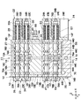
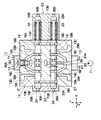
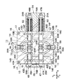
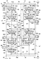
- FIG. 3 is a longitudinal sectional view of the multiple valve device as viewed in the direction of arrows IV-IV in FIG. 2;
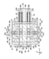
- FIG. 3 is a longitudinal cross-sectional view of the multiple valve device as viewed in the direction of arrows VV in FIG. 2;
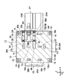
- FIG. 3 is a longitudinal cross-sectional view of the multiple valve device as viewed in the direction of arrows VI-VI in FIG.
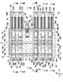
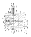
- FIG. 6 is a cross-sectional view of the first housing block together with a control valve for a bucket and a spare control valve as viewed in the direction of arrows VIII-VIII in FIG. 5;
- FIG. 6 is a cross-sectional view of the first housing block together with a relief valve as viewed in the direction of arrows IX-IX in FIG. 5;
- FIG. 6 is a cross-sectional view of a second housing block together with a boom control valve as viewed in the direction of arrows XX in FIG. 5;
- FIG. 6 is a cross-sectional view of the second housing block together with a control valve for an arm, as viewed in the direction of arrows XI-XI in FIG. 5; It is the cross-sectional view which saw the 2nd housing block with the control valve for revolutions, and was seen from the arrow XII-XII direction in FIG.
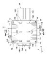
- FIG. 6 is a cross-sectional view of the second housing block as viewed from the direction of arrows XIII-XIII in FIG. 5 at the position of the mating surface.
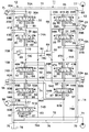
- It is a hydraulic circuit diagram of the multiple valve apparatus used for the hydraulic shovel shown in FIG. It is a hydraulic circuit figure of the multiple valve apparatus by a comparative example.
- FIG. 6 is a hydraulic circuit diagram of a multiple valve device according to a second embodiment.
- a total of four spool sliding holes are provided in the first housing block as a representative example of the multiple valve device, and a total of five spool slidings are provided in the second housing block.
- the case where a hole is provided is mentioned as an example.
- the multiple valve device according to the present invention is not limited to this, and among the valve housing provided with 6 to 12 spool slide holes, three to six in the first housing block are provided. It is also possible to provide a spool sliding hole and to provide three to six spool sliding holes in the second housing block.
- FIGS. 1 to 14 show a multiple valve device according to a first embodiment of the present invention.
- reference numeral 1 denotes a hydraulic shovel as a construction machine, and the hydraulic shovel 1 is rotatably mounted on a crawler type lower traveling body 2 capable of self-propelled movement and the lower traveling body 2 as shown in FIG. It comprises the upper revolving superstructure 3 and a working device 7 described later.
- the upper swing body 3 of the hydraulic shovel 1 constitutes a vehicle body of a construction machine together with the lower traveling body 2.
- the upper swing body 3 has a swing frame 3A which is swing-driven on the lower traveling body 2, and a cab 4, which will be described later, a counterweight 5, and a building cover 6 are provided on the swing frame 3A.
- the cab 4 is disposed on the front left side of the swing frame 3A.
- the cab 4 is formed as a substantially rectangular box, and defines a cab inside.
- a control lever for operation and a travel lever are provided inside the cab 4, in addition to the driver's seat on which the operator is seated.
- the counterweight 5 is provided on the rear end side of the swing frame 3A.
- the counterweight 5 is detachably mounted on the rear end side of the swing frame 3A, and balances the weight of the entire upper swing body 3 with respect to the work device 7 on the front side.
- a building cover 6 described later that accommodates an engine (not shown) is provided on the front side of the counterweight 5.
- the building cover 6 is located between the cab 4 and the counterweight 5 and is erected on the swing frame 3A.
- the building cover 6 is formed using, for example, a plurality of metal panels made of thin steel plates, and defines a machine room (not shown) for housing the engine therein.
- hydraulic pumps 77 and 79 (see FIG. 14) described later, which are rotationally driven by the engine, are provided.
- a multiple valve device 11 described later is provided at a position near the cab 4.
- the working device 7 is provided at the front of the upper swing body 3 so as to be capable of raising and lowering.
- the work device 7 has, for example, an excavating operation of earth and sand, with a boom 8 attached to the pivot frame 3A so as to be capable of raising and lowering the base end side, and an arm 9 attached to the tip end side of the boom 8 so as to be raised and lowered.
- a bucket 10 as a work tool rotatably provided on the tip end side of the arm 9 is configured.
- the boom 8 of the working device 7 is raised and lowered up and down with respect to the turning frame 3A by the boom cylinder 8A, and the arm 9 is raised and lowered up and down by the arm cylinder 9A on the tip end side of the boom 8.
- the bucket 10 as a work implement is pivoted up and down by a bucket cylinder 10A as a work implement cylinder on the tip end side of the arm 9.
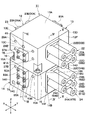
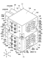
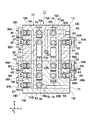
- the multiple valve device 11 includes a valve housing 12, spools 27, 31, 35, 39, 49, 51, 56, 58, 62 and a relief valve 88 described later. It consists of As shown in FIGS. 2 to 6, the valve housing 12 of the multiple valve device 11 is divided into two by a first housing block 13 and a second housing block 14 described later.
- first housing block 13 and the second housing block 14 are in the left and right directions (X-axis direction in FIG. 2) parallel to the mating surfaces 13B and 14A described later and in the front and rear directions (Y It is formed as a rectangular block extending in the axial direction and also extending upward and downward (in the Z-axis direction) perpendicular to the mating surfaces 13B and 14A.
- the first housing block 13 and the second housing block 14 are detachably engaged with each other at the position of the mating surfaces 13B and 14A.
- Reference numeral 13 denotes a first housing block which is a half of the valve housing 12, and the first housing block 13 is formed as a rectangular parallelepiped cast product as shown in FIGS. There is.
- the first housing block 13 has a total of six, including an upper surface 13A (hereinafter referred to as the upper surface 13A), a lower mating surface 13B, front and rear side surfaces 13C and 13D, and left and right side surfaces 13E and 13F. It has a face.
- a pump port 65 described later is provided in the first housing block 13 at a position above the cover 81A described later among the side surfaces 13C on the front side.
- pressure oil supply and discharge ports 29A and 29B and pressure oil supply and discharge ports 37A and 37B which will be described later, are respectively opened at positions separated in the left and right directions (X axis direction).
- the rear side surface 13D is opened at positions separated in the left and right directions (X-axis direction) respectively, and pressure oil supply and discharge ports 33A, 33B and pressure oil supply and discharge ports described later are provided. 41A and 41B are provided.
- a second housing block 14 constitutes another half of the valve housing 12.
- the second housing block 14 is also molded as a rectangular block (casting) by casting means.
- the second housing block 14 has a total of six pieces including an upper mating surface 14A, a lower other surface 14B (hereinafter referred to as a lower surface 14B), front and rear side surfaces 14C and 14D and left and right side surfaces 14E and 14F. Have a face.
- a pump port 71 described later is provided in the second housing block 14 at a position below the cover 85A described later among the side surfaces 14C on the front side.
- a tank port 75 described later is provided so as to be open at a position on the left side in the X-axis direction more than that.
- Pressure oil supply and discharge ports 53A and 53B which will be described later, are provided separately on the front side surface 14C in the left and right directions (X-axis direction).
- pressure oil supply and discharge ports 60A and 60B and pressure oil supply and discharge ports 64A and 64B which will be described later, are spaced apart in the left and right directions (X-axis direction) on the rear side 14D. It is provided.
- a plurality of (for example, a total of four) recessed portions 15 are formed. Recesses 15 are located at positions above the mating surface 13B at four corners of the first housing block 13 (ie, front and rear side surfaces 13C and 13D and left and right side surfaces). 13E and 13F are provided at the corners). Each recessed portion 15 is formed by cutting out the corner portion in an L-shaped cross section.
- a seating surface portion 15A for bolt fastening is formed between the mating surface 13B and the lower surface side of each recessed portion 15.
- These seat portions 15A constitute a fastening portion for fixing (connecting) the first housing block 13 to the second housing block 14 in a state of abutment with each other using a plurality of bolts 16.
- the recessed portion 15 forms a bolt mounting space for the bolt 16 at the upper position of the seat portion 15A.
- the seat portion 15A (fastening portion) of each recessed portion 15 is provided at a position closer to the mating surface 13B than each spool valve including the bucket control valve 34 and the spare control valve 38. That is, the seat portion 15A constituting the fastening portion is disposed at a position between the spool valve and the mating surface 13B.
- Screw holes 17 are formed in the second housing block 14 at positions facing the seating surface portions 15A at the top and bottom in the mating surface 14A. Bolts 16 are screwed into these screw holes 17, respectively. Thereby, the first housing block 13 and the second housing block 14 are fixed in an abutting state by using a total of four bolts 16 to constitute the valve housing 12 of the multiple valve device 11 .
- Reference numerals 18, 19, 20 and 21 denote four spool slide holes provided in the first housing block 13.
- the spool slide holes 18 to 21 are disposed in the first housing block 13 so as to have a three-dimensional structure similar to a cover 22 (see FIG. 2) described later. As shown in FIG. 4, FIG. 5, FIG. 7, and FIG. 8, the spool sliding holes 18 to 21 extend parallel to each other along the X axis direction, and are spaced apart from each other in the Y axis direction and Z axis direction. There is.
- the number of spool sliding holes provided in the first housing block 13 is not limited to four, and three spool sliding holes may be provided as a minimum so as to form a three-dimensional structure.
- the first housing block 13 is provided with, for example, a total of three spool slide holes 18, 19 and 20 for the travel control valves 26 and 30 and the bucket control valve 34 described later, for example.
- the spool sliding hole 21 may be omitted.
- the spool sliding holes 18 and 19 extend in parallel in the X axis direction as shown in FIG. 7, and are arranged at a predetermined interval in the Y axis direction.
- the spool slide holes 20 and 21 also extend in parallel in the X axis direction as shown in FIG. 8 and are arranged at a predetermined interval in the Y axis direction.
- the spool slide holes 18 and 20 extend parallel to each other along the X-axis direction as shown in FIG. 4 and are arranged at predetermined intervals in the Z-axis direction.
- the spool slide holes 19 and 21 also extend parallel to each other along the X axis direction, and are arranged at a predetermined interval in the Z axis direction.
- annular oil grooves 18A and 18B are formed axially spaced apart on the peripheral wall side of the spool sliding hole 18, and the oil grooves 18A and 18B are formed.
- Other annular oil grooves 18C and 18C are formed between them.
- another oil groove 18D, 18D is formed at a position that is axially outside the oil groove 18A, 18B.
- the oil grooves 18A to 18D become oil grooves on the pressure oil supply and discharge side and communicate with pressure oil supply and discharge ports 29A and 29B for traveling right described later, and the actuator side oil passage Is what constitutes
- Each oil groove 18C becomes an oil groove on the high pressure side and is in communication with a pump passage 66 and a high pressure passage 68, 69 on the pump port 65 side described later.
- Each oil groove 18D is an oil groove on the low pressure side and is in communication with a side passage 70B of a low pressure passage 70 on the side of a tank 78 described later.
- These oil grooves 18C and 18D constitute an oil pressure source side oil passage.
- oil grooves 19A and 19B on the pressure oil supply / discharge side constituting the actuator side oil passage and oil grooves on the high pressure side on the peripheral wall side of the spool sliding hole 19.
- the oil grooves 19C and 19C and the oil grooves 19D and 19D on the low pressure side are formed to be separated from each other in the axial direction.
- These oil grooves 19C and 19D constitute an oil pressure source side oil passage.
- 20C, 20C, and oil grooves 20D, 20D on the low pressure side are formed to be axially separated from each other.
- the oil grooves 21D and 21D are formed separately from each other in the axial direction.
- the cover body 22 is provided on the side surface 13F of the first housing block 13. As shown in FIG. 2, the cover 22 has a total of four cylindrical projections 22A, 22B, 22C, 22D, and these cylindrical projections 22A to 22D are control valves 26, 30 described later. , 34, and 38 constitute the hydraulic pilot units 26B, 30B, 34B, and 38B.
- the cylindrical projections 22A, 22B, 22C, 22D are coaxial with the spool slide holes 18, 19, 20, 21 and the side surfaces of the housing block 13. It projects from 13F in the X-axis direction. That is, the cylindrical protrusions 22A to 22D extend in parallel to each other along the X-axis direction in the same manner as the spool sliding holes 18 to 21, and are arranged in an arrangement relationship of three-dimensional structure mutually separated in the Y-axis direction and the Z-axis direction. It is set up.
- Another cover body 23 is provided on the side surface 13 E of the first housing block 13. As shown in FIG. 3, the other cover body 23 has a total of four short cylindrical parts 23A, 23B, 23C, and 23D. These cylindrical portions 23A to 23D constitute hydraulic pilot portions 26A, 30A, 34A, 38A of control valves 26, 30, 34, 38 described later.
- the cover body 24 is provided on the side surface 14F of the second housing block 14. As shown in FIG. 2, the cover body 24 has a total of five cylindrical protrusions 24A, 24B, 24C, 24D, 24E. These cylindrical projections 24A to 24E constitute hydraulic pilot parts 47B, 48B, 54B, 55B, 61B of control valves 47, 48, 54, 55, 61 described later.
- the cylindrical protrusions 24A, 24B, 24C, 24D, 24E are coaxial with the spool slide holes 42, 43, 44, 45 and 46 described later. And projects from the side surface 14F of the housing block 14 in the X-axis direction. That is, similar to the spool sliding holes 42 to 46, the cylindrical protrusions 24A to 24E extend in parallel to each other along the X axis direction, and are arranged in an arrangement relationship of three-dimensional structure separated from each other in the Y axis direction and Z axis direction. It is set up.
- Another cover 25 is provided on the side surface 14E of the second housing block 14. As shown in FIG. 3, the other cover body 25 has a total of five short cylindrical parts 25A, 25B, 25C, 25D, 25E. These cylindrical portions 25A to 25E constitute hydraulic pilot portions 47A, 48A, 54A, 55A, 61A of control valves 47, 48, 54, 55, 51 described later.
- Reference numeral 26 denotes a direction control valve for travel right (hereinafter referred to as travel control valve 26) provided in the first housing block 13.
- the travel control valve 26 is constituted by a spool valve formed by inserting the spool 27 into the spool sliding hole 18.
- the travel control valve 26 is located on both sides in the axial direction of the spool 27 and has left and right hydraulic pilot parts 26A and 26B in the cover bodies 22 and 23.
- the right side hydraulic pilot portion 26B is provided with a spring 28 which always biases the spool 27 toward the neutral position.
- a pilot pressure is supplied to the hydraulic pressure pilot parts 26A, 26B of the travel control valve 26 from an operation valve (not shown) of the travel lever.
- the spool 27 of the travel control valve 26 axially displaces the spool sliding hole 18 in accordance with the pilot pressure, and the oil grooves 18A and 18B on the actuator side are selectively selected relative to the oil grooves 18C and 18D on the hydraulic pressure source side. Connect and shut off. As a result, the traveling control valve 26 switches from the neutral position (A) in FIG. 14 to the left and right switching positions (B) and (C).
- the pressure oil supply and discharge ports 29A and 29B are provided on the side surface 13C of the first housing block 13. As shown in FIG. 7, these pressure oil supply and discharge ports 29A and 29B are in communication with the oil grooves 18A and 18B on the actuator side, and open on the other side 13C of the first housing block 13 (see FIG. See Figure 2). As shown in FIG. 14, the pressure oil supply and discharge ports 29A and 29B are provided with pressure oil discharged from a hydraulic pump 77 described later on the lower traveling body 2 (see FIG. 1) for left and right traveling motors 2L and 2R. For example, it supplies the driving motor 2R on the right side.
- Reference numeral 30 denotes a traveling left direction control valve (hereinafter referred to as a traveling control valve 30) provided in the first housing block 13.
- the travel control valve 30 is constituted by a spool valve formed by inserting the spool 31 into the spool sliding hole 19.
- the travel control valve 30 is located on both sides of the spool 31 in the axial direction, and has left and right hydraulic pilot parts 30A, 30B in the cover bodies 22, 23.
- the hydraulic pilot portion 30B is provided with a spring 32 which always biases the spool 31 toward the neutral position.
- a pilot pressure is supplied to the hydraulic pressure pilot sections 30A and 30B of the travel control valve 30 from an operation valve (not shown) of the travel lever.
- the spool 31 of the travel control valve 30 axially displaces the inside of the spool sliding hole 19 according to the pilot pressure, and the oil grooves 19A and 19B on the actuator side are selectively selected relative to the oil grooves 19C and 19D on the hydraulic source side. Communicate with and shut off. As a result, the traveling control valve 30 is switched from the neutral position (A) in FIG. 14 to the left and right switching positions (B) and (C).
- the other pressure oil supply and discharge ports 33A, 33B are provided on the side surface 13D of the first housing block 13. As shown in FIG. 7, the other pressure oil supply and discharge ports 33A and 33B communicate with the oil grooves 19A and 19B on the actuator side on one side, and open on the other side 13D of the first housing block 13 ( See Figure 3). As shown in FIG. 14, the pressure oil supply and discharge ports 33A and 33B are provided, for example, in the left and right traveling motors 2L and 2R for providing the lower traveling body 2 with pressure oil discharged from a hydraulic pump 79 described later. It supplies the driving motor 2L on the left side.
- Reference numeral 34 denotes a direction control valve for work tools (hereinafter referred to as a bucket control valve 34) provided in the first housing block 13.
- the bucket control valve 34 is constituted by a spool valve formed by inserting the spool 35 into the spool sliding hole 20.
- the bucket control valve 34 is provided with left and right hydraulic pilot parts 34A and 34B in the cover bodies 22 and 23 positioned on both sides of the spool 35 in the axial direction.
- the right side hydraulic pilot portion 34B is provided with a spring 36 which always biases the spool 35 toward the neutral position.
- a pilot pressure is supplied to the hydraulic pilot parts 34A and 34B of the bucket control valve 34 from a control valve (not shown) of the bucket control lever.
- the spool 35 of the bucket control valve 34 is axially displaced in the spool sliding hole 20 according to the pilot pressure, and the oil grooves 20A and 20B on the actuator side are selectively selected relative to the oil grooves 20C and 20D on the hydraulic source side. Communicate with and shut off.
- the bucket control valve 34 is switched from the neutral position (A) in FIG. 14 to the left and right switching positions (B) and (C).
- the pressure oil supply and discharge ports 37A and 37B are provided on the side surface 13C of the first housing block 13. As shown in FIG. 8, these pressure oil supply and discharge ports 37A and 37B communicate with the oil grooves 20A and 20B on the actuator side on one side, and open on the other side 13C of the first housing block 13 (see FIG. See Figure 2).
- the pressure oil supply and discharge ports 37A and 37B supply pressure oil to the bucket cylinder 10A (see FIG. 1) of the working device 7.
- Reference numeral 38 denotes a spare directional control valve (hereinafter referred to as spare control valve 38) provided in the first housing block 13.
- the spare control valve 38 is constituted by a spool valve formed by inserting the spool 39 into the spool sliding hole 21.
- Left and right hydraulic pilot sections 38A and 38B are provided in the cover bodies 22 and 23 on the both sides of the spool 39 in the axial direction of the spare control valve 38.
- the right side hydraulic pilot portion 38B is provided with a spring 40 for always biasing the spool 39 toward the neutral position.
- the hydraulic pilot parts 38A and 38B of the spare control valve 38 are supplied with pilot pressure from the operating valve (not shown) of the spare operating lever.
- the spool 39 of the spare control valve 38 is axially displaced in the spool sliding hole 21 according to the pilot pressure, and the oil grooves 21A and 21B on the actuator side are selectively selected relative to the oil grooves 21C and 21D on the hydraulic source side. Communicate with and shut off.
- the spare control valve 38 is switched from the neutral position (A) in FIG. 14 to the left and right switching positions (B) and (C).
- the other pressure oil supply and discharge ports 41A and 41B are provided on the side surface 13D of the first housing block 13. As shown in FIG. 8, these pressure oil supply and discharge ports 41A and 41B communicate with the oil grooves 21A and 21B on the actuator side on one side, and open on the other side 13D of the first housing block 13 (See Figure 3).
- the pressure oil supply and discharge ports 41A and 41B supply pressure oil to a spare hydraulic actuator (not shown).
- Reference numerals 42, 43, 44, 45 and 46 denote five spool slide holes provided in the second housing block 14.
- the spool slide holes 42 to 46 are disposed in the second housing block 14 in a three-dimensional structure corresponding to the cover body 24 (see FIG. 2). As shown in FIGS. 4, 5, and 10 to 12, the spool slide holes 42 to 46 extend parallel to each other along the X-axis direction, and are spaced apart from each other in the Y-axis direction and the Z-axis direction. There is.
- the number of spool sliding holes provided in the second housing block 14 is not limited to five, and three spool sliding holes may be provided as a minimum so as to form a three-dimensional structure.
- the second housing block 14 is provided with, for example, a total of three spool slide holes 42, 44 and 46 of the boom control valve 47, the arm control valve 54, and the turning control valve 61, and boom control
- the valve 48 and the spool slide holes 43 and 45 of the arm control valve 55 may be omitted.
- the spool sliding holes 42 and 43 extend in parallel in the X-axis direction and are arranged at a predetermined interval in the Y-axis direction.
- the spool sliding holes 45 and 46 extend in parallel in the X-axis direction, and are arranged at a predetermined interval in the Y-axis direction.
- the spool slide holes 42 and 44 extend parallel to each other along the X-axis direction and are spaced apart in the Z-axis direction.
- the spool sliding holes 45 are arranged between the spool sliding holes 43 and 46 in the Z-axis direction, and these spool sliding holes 43, 45 and 46 are X It extends parallel to each other along the axial direction.
- annular oil grooves 42A and 42B are formed in the second housing block 14 on the peripheral wall side of the spool sliding hole 42 so as to be axially separated.
- Other annular oil grooves 42C, 42C are formed between the oil grooves 42A, 42B.
- another oil groove 42D, 42D is formed at a position that is axially outside the oil grooves 42A, 42B.
- each oil groove 42C becomes an oil groove on the high pressure side and communicates with a high pressure passage 69 on the hydraulic pump 77 side described later, and each oil groove 42D becomes an oil groove on the low pressure side and the tank side described later It is in communication with the directional passage 76B.
- the oil groove 42C constitutes an oil pressure source side oil passage.
- oil grooves 43A, 43B on the pressure oil supply / discharge side constituting the actuator side oil passage on the peripheral wall side of the spool sliding hole 43, and oil on the high pressure side
- the grooves 43C and 43C, and the oil grooves 43D and 43D on the low pressure side are formed to be separated from each other in the axial direction.
- the oil groove 43C constitutes an oil pressure source side oil passage.
- oil grooves 44A and 44B on the pressure oil supply / discharge side constituting the actuator side oil passage, and a high pressure side oil groove constituting the hydraulic pressure source side oil passage are formed to be separated from each other in the axial direction.
- oil grooves 45A, 45B on the pressure oil supply / discharge side constituting the actuator side oil passage, oil grooves 45C, 45C on the high pressure side constituting the hydraulic pressure source side oil passage, low pressure side are formed to be separated from each other in the axial direction.
- oil grooves 46A, 46B on the pressure oil supply / discharge side constituting the actuator side oil passage oil grooves 46C, 46C on the high pressure side, low pressure
- oil grooves 46D, 46D on the side are formed axially separated from each other. These oil grooves 46C and 46D constitute a hydraulic pressure source side oil passage.
- Reference numerals 47 and 48 denote directional control valves for the boom provided on the second housing block 14 (hereinafter referred to as boom control valves 47 and 48).
- one of the boom control valves 47 and 48 is a spool valve formed by inserting the first boom spool 49 into the spool sliding hole 42. It is configured.
- the boom control valve 47 is located on both sides of the boom spool 49 in the axial direction, and has left and right hydraulic pilot parts 47A, 47B in the cover bodies 24, 25.
- the hydraulic pilot portion 47B on the right side is provided with a spring 50 for always biasing the boom spool 49 toward the neutral position.
- pilot pressure is supplied to the hydraulic pilot parts 47A and 47B of the boom control valve 47 from an operation valve (not shown) of the boom control lever.
- the boom spool 49 of the boom control valve 47 axially displaces the inside of the spool sliding hole 42 according to the pilot pressure, and the oil grooves 42A and 42B on the actuator side with respect to the oil grooves 42C and 42D on the hydraulic source side Selectively communicate and shut off.
- the boom control valve 47 switches from the neutral position (A) in FIG. 14 to the left and right switching positions (B) and (C).
- the other boom control valve 48 among the boom control valves 47 and 48 is constituted by a spool valve formed by inserting and fitting the second boom spool 51 into the spool sliding hole 43.
- the other boom control valve 48 is located axially on both sides of the boom spool 51 and has left and right hydraulic pilot parts 48A, 48B in the cover bodies 24, 25.
- the right side hydraulic pilot portion 48B is provided with a spring 52 for always biasing the boom spool 51 toward the neutral position.
- pilot pressure is supplied from the operation valve to the hydraulic pilot portions 48A and 48B of the boom control valve 48 in the same manner as the boom control valve 47 described above.
- the boom spool 51 of the boom control valve 48 axially displaces the inside of the spool sliding hole 43 in accordance with the pilot pressure, and the oil grooves 43A and 43B on the actuator side with respect to the oil grooves 43C and 43D on the hydraulic source side Selectively communicate and shut off. Thereby, the boom control valve 48 is switched from the neutral position (A) in FIG. 14 to the left and right switching positions (B) and (C).
- the pressure oil supply and discharge ports 53A and 53B are provided on the side surface 14C of the housing block 14. As shown in FIG. 10, these pressure oil supply and discharge ports 53A and 53B communicate with oil grooves 42A and 42B on one side on the actuator side and oil grooves 43A and 43B via joining passages 93A and 93B described later, The other side is open to the side surface 14C of the housing block 14 (see FIG. 2).
- the pressure oil supply and discharge ports 53A and 53B supply pressure oil to the boom cylinder 8A (see FIG. 1) of the working device 7.
- the boom control valves 47 and 48 cause the pressure oil discharged from the hydraulic pumps 77 and 79 described later to merge with each other in the second housing block 14 (merging passages 93A and 93B described later).
- the pressure oil joined at this time is supplied to the boom cylinder 8A of the working device 7 through the pressure oil supply and discharge ports 53A, 53B.
- the boom control valves 47 and 48 are in a relationship in which the pressure oil from the two hydraulic pumps 77 and 79 merge with each other. Therefore, the boom spools 49 and 51 of the boom control valves 47 and 48 are provided in the same second housing block 14.
- Reference numerals 54 and 55 denote direction control valves for the arm provided on the second housing block 14 (hereinafter referred to as arm control valves 54 and 55).
- arm control valves 54 and 55 As shown in FIG. 11, among the arm control valves 54 and 55, one arm control valve 54 is a spool valve formed by inserting and fitting the first arm spool 56 into the spool sliding hole 44. It is configured.
- the arm control valve 54 is located on both sides of the arm spool 56 in the axial direction, and has left and right hydraulic pilot parts 54A and 54B in the cover bodies 24 and 25.
- the right side hydraulic pilot section 54B is provided with a spring 57 for always biasing the arm spool 56 toward the neutral position.
- a pilot pressure is supplied to the hydraulic pressure pilot portions 54A and 54B of the arm control valve 54 from an operation valve (not shown) of the arm operation lever.
- the arm spool 56 of the arm control valve 54 axially displaces the inside of the spool sliding hole 44 according to the pilot pressure, and the oil grooves 44A and 44B on the actuator side with respect to the oil grooves 44C and 44D on the hydraulic source side Selectively communicate and shut off.
- the arm control valve 54 switches from the neutral position (A) in FIG. 14 to the left and right switching positions (B) and (C).
- the other arm control valve 55 among the arm control valves 54 and 55 is configured by a spool valve formed by inserting and fitting the second arm spool 58 into the spool sliding hole 45.
- the other arm control valve 55 is located on both sides in the axial direction of the arm spool 58, and has left and right hydraulic pilot parts 55A, 55B in the cover bodies 24, 25.
- the right side hydraulic pilot portion 55B is provided with a spring 59 for always biasing the arm spool 58 toward the neutral position.
- pilot pressure is supplied to the hydraulic pressure pilot parts 55A and 55B of the arm control valve 55 from the operation valve in the same manner as the arm control valve 54 described above.
- the arm spool 58 of the arm control valve 55 axially displaces the inside of the spool sliding hole 45 in accordance with the pilot pressure, and the oil grooves 45A and 45B on the actuator side with respect to the oil grooves 45C and 45D on the hydraulic source side Selectively communicate and shut off.
- the arm control valve 55 is switched from the neutral position (A) in FIG. 14 to the switching position (B), (C), and together with the arm control valve 54, the pressure oil supply and discharge port 60A, 60B side described later.
- the pressure oil supply and discharge ports 60A and 60B are provided on the side surface 14D of the housing block 14. As shown in FIG. 11, these pressure oil supply / discharge ports 60A, 60B communicate with the oil grooves 44A, 44B and the oil grooves 45A, 45B on the actuator side via merging passages 94A, 94B described later on one side, The other side is open to the side surface 14D of the housing block 14 (see FIG. 3).
- the pressure oil supply and discharge ports 60A and 60B supply pressure oil to the arm cylinder 9A (see FIG. 1) of the working device 7.
- the arm control valves 54 and 55 cause the pressure oil discharged from the hydraulic pumps 77 and 79 described later to merge with each other in the second housing block 14 (merging passages 94A and 94B described later).
- the pressure oil joined at this time is supplied to the arm cylinder 9A of the working device 7 through the pressure oil supply and discharge ports 60A and 60B.
- the arm control valves 54 and 55 are in a relationship in which the pressure oil from the two hydraulic pumps 77 and 79 merge with each other. Therefore, the arm spools 56 and 58 of the arm control valves 54 and 55 are provided in the same second housing block 14.
- Reference numeral 61 denotes a turning direction control valve (hereinafter referred to as a turning control valve 61) provided in the second housing block 14.
- the turning control valve 61 is constituted by a spool valve formed by inserting the spool 62 into the spool sliding hole 46.
- the turning control valve 61 is located on both sides in the axial direction of the spool 62 and has left and right hydraulic pilot parts 61A, 61B in the cover bodies 24, 25.
- the right side hydraulic pilot portion 61B is provided with a spring 63 for always urging the spool 62 toward the neutral position.
- a pilot pressure is supplied to the hydraulic pilot parts 61A and 61B of the turning control valve 61 from an operation valve (not shown) of the turning operation lever.
- the spool 62 of the swing control valve 61 axially displaces the inside of the spool sliding hole 46 according to the pilot pressure, and the oil grooves 46A and 46B on the actuator side are selectively selected relative to the oil grooves 46C and 46D on the hydraulic source side. Communicate with and shut off.
- the turning control valve 61 is switched from the neutral position (A) in FIG. 14 to the switching positions (B) and (C).
- the pressure oil supply and discharge ports 64A and 64B are provided on the side surface 14C of the housing block 14. As shown in FIG. 12, these pressure oil supply and discharge ports 64A, 64B are in communication with the oil grooves 46A, 46B on the actuator side, and are open at the side surface 14D of the housing block 14 (see FIG. 3). ). And as shown in FIG. 14, pressure oil supply / discharge ports 64A, 64B supply pressure oil to the turning motor 3M provided on the upper swing body 3 (see FIG. 1) side.
- first and second pump ports 65 and 71 a pump passage 66, a center bypass passage 67 and 73, high pressure passages 68, 69 and 74, and a low pressure passage 70 provided in the valve housing 12 of the multiple valve device 11.
- the tank port 75, the tank passage 76, the first and second hydraulic pumps 77 and 79, and the relief valve 88 will be described.
- the plurality of hydraulic pressure source side oil passages provided in the valve housing 12 of the multiple valve device 11 are, as described later, a first high pressure passage 69 to which pressure oil is supplied from the first hydraulic pump 77; And a second high pressure passage 74 to which pressure oil is supplied from the hydraulic pump 79 of FIG.
- the first high pressure passage 69 and the second high pressure passage 74 are disposed near the center side of the joint surfaces 13B and 14A surrounded by the recessed portions 15 of the valve housing 12.
- the first pump port 65 is provided on the side surface 13 C of the first housing block 13. As shown in FIG. 2, the first pump port 65 opens at the center of the side surface 13C at a position above the cover 81A described later and is connected to the discharge side of the hydraulic pump 77 described later. is there. The first pump port 65 opens at the side surface 13C of the first housing block 13 at a position close to the upper surface 13A opposite to the mating surface 13B with the spool slide holes 18, 19, 20, 21 interposed therebetween. Is provided. As shown in FIG. 6, the first pump port 65 communicates with the pump passage 66, the center bypass passage 67 and the high pressure passages 68 and 69 which are bored in the first housing block 13.
- the center bypass passage 67 and the high pressure passage 68 communicate with the first pump port 65 via the pump passage 66.
- the first high pressure passage 69 is a passage branched from the first passage 67A of the center bypass passage 67 between the travel control valve 26 and the bucket control valve 34. is there.
- the first high pressure passage 69 is disposed at a position closer to the side surface 13C of the housing block 13 than the first passage 67A of the center bypass passage 67 (see FIGS. 6, 8 and 9).
- the center bypass passage 67 and the first high pressure passage 69 are formed to extend upward and downward (Z-axis direction) from the first housing block 13 into the second housing block 14. ing.
- the center bypass passage 67 is formed in the first housing block 13 and extends upward and downward to a first passage 67A on the first pump side, and a second housing block 14 It includes a second passage 67B on the first pump side which is formed inside and extends downward, and a connection port 67C which causes the passages 67A and 67B to communicate with each other at the position of the mating surfaces 13B and 14A. There is.
- the connection ports 67C connect the first and second passages 67A and 67B of the center bypass passage 67 in a fluid-tight manner above and below the mating surfaces 13B and 14A (see FIG. 6).
- the first high pressure passage 69 is formed in the first housing block 13 and extends upward and downward, the first oil passage 69A on the first pump side, and the second housing block 14 is formed in the upper and lower directions.
- the connection port 69C connects the first and second oil passages 69A and 69B of the first high pressure passage 69 in a fluid-tight manner above and below the mating surfaces 13B and 14A.
- connection port 67C of the center bypass passage 67 and the connection port 69C of the first high pressure passage 69. 16 and the low pressure side oil passages are disposed closer to the center side of the mating surface 14A. That is, the connection port 67C of the center bypass passage 67 and the connection port 69C of the first high pressure passage 69 are disposed at positions closer to the center side of the mating surfaces 13B and 14A surrounded by the recessed portions 15 of the valve housing 12 It is done.
- the pump passage 66 and the first high pressure passage 69 use the pressure oil discharged from the first hydraulic pump 77 as the travel control valve 26, the bucket control valve 34, the boom control valve 47, and the arm control valve. It constitutes the high pressure side of the oil pressure source side oil passage which is supplied to the V. 54.
- the first oil passage 69A of the first high-pressure passage 69 branches between the traveling control valve 26 and the bucket control valve 34 from the first passage 67A of the center bypass passage 67.
- the downstream side extends to the position of the connection port 69C. That is, the first oil passage 69A of the first high pressure passage 69 constitutes a first oil passage on the first pump side.
- An upstream side of the second oil passage 69B of the first high pressure passage 69 communicates with the connection port 69C between the mating surfaces 13B and 14A, and a downstream side is connected in parallel to the boom control valve 47 and the arm control valve 54.
- the second oil passage 69B of the first high pressure passage 69 constitutes a second oil passage on the first pump side.
- the first oil passage 69A of the first high pressure passage 69 is located upstream of the bucket control valve 34 (spool 35) disposed at a position close to the mating surface 13B of the first housing block 13.
- the pressure oil from the first hydraulic pump 77 is supplied to the second oil passage 69B and the control valves 47 and 54 (spools 49 and 56) through the connection port 69C between the mating surfaces 13B and 14A.
- the low pressure passage 70 is formed in the first housing block 13. As shown in FIGS. 4 to 9, the low pressure passage 70 is formed at a position separated from the pump passage 66, the center bypass passage 67, and the high pressure passages 68 and 69.
- the low pressure passage 70 has a plurality of (two) upper passages 70A extending along the upper surface 13A of the first housing block 13 and an upper end side in communication with the respective upper passages 70A and the left and right of the first housing block 13 It is configured to include left and right side passages 70B extending downward along the side surfaces 13E and 13F.
- each side passage 70B of the low pressure passage 70 communicates with each side passage 76B of a tank passage 76 described later at the position of the mating surface 13B. Therefore, the oil (return oil from each hydraulic actuator) flowing in the upper passage 70A and the side passage 70B of the low pressure passage 70 is discharged to the tank 78 described later via the tank passage 76.
- the second pump port 71 is provided on the side surface 14 C of the second housing block 14. As shown in FIG. 2, the second pump port 71 opens at the center of the side surface 14C at a position below the cover 85A described later, and is connected to the discharge side of a second hydraulic pump 79 described later It is The second pump port 71 is disposed on the side surface 14C of the second housing block 14 at a position close to the lower surface 14B opposite to the mating surface 14A with the respective spool slide holes 42, 43, 44, 45 and 46 interposed therebetween. It is provided open. The second pump port 71 communicates with the pump passage 72 bored in the second housing block 14 and also communicates with the center bypass passage 73 and the second high pressure passage 74. The center bypass passage 73 and the second high pressure passage 74 are formed to extend in the Z-axis direction from the second housing block 14 to the first housing block 13.
- the second high pressure passage 74 branches from the pump passage 72 at a position upstream of the turning control valve 61, and at this branch position, the center bypass passage 73 is a pump passage. Connected to 72. As shown in FIG. 6, the second high pressure passage 74 is disposed closer to the side surfaces 13 D and 14 D of the housing blocks 13 and 14 than the center bypass passage 73. The center bypass passage 73 and the second high pressure passage 74 are formed to extend upward from the second housing block 14 into the first housing block 13.
- the center bypass passage 73 is formed in the first housing block 13 and extends upward and downward to a first passage 73A on the second pump side, and a second housing block 14 It includes a second passage 73B on the second pump side, which is formed inside and extends downward, and a connection port 73C which causes the passages 73A and 73B to communicate with each other at the position of the mating surfaces 13B and 14A. There is.
- the connection ports 73C connect the first and second passages 73A and 73B of the center bypass passage 73 in a fluid-tight manner above and below the mating surfaces 13B and 14A (see FIG. 6).
- a second high pressure passage 74 connected to the second hydraulic pump 79 is formed in the first housing block 13 and extends upward and downward, a first oil passage 74A on the second pump side, and a second oil passage 74A.
- the second pump-side second oil passage 74B formed in the housing block 14 and extending downward is communicated with the first and second oil passages 74A and 74B at the position of the mating surfaces 13B and 14A.
- a connection port 74C is connected to the first and second oil passages 74A and 74B of the second high pressure passage 74 in a fluid-tight manner above and below the mating surfaces 13B and 14A.
- connection port 73C of the center bypass passage 73 and the connection port 74C of the high pressure passage 74 are provided with four bolts 16 and a low voltage provided at four corners of the second housing block 14.
- the side oil passages i.e., the side passages 70B of the low pressure passage 70 and the side passages 76B of the tank passage 76 described later
- the connection port 73C of the center bypass passage 73 and the connection port 74C of the second high pressure passage 74 are disposed at positions closer to the center side of the mating surfaces 13B and 14A surrounded by the recessed portions 15 of the valve housing 12 It is done.
- the pump passage 72 and the second high pressure passage 74 are configured to control the pressure oil discharged from the second hydraulic pump 79 described later, the turning control valve 61, the arm control valve 55, the boom control valve 48, and the spare control valve. 38, the high pressure side of the hydraulic pressure source side oil passage supplied to the traveling control valve 30 and the like.
- the first oil passage 74A of the second high pressure passage 74 has its upstream side in communication with the connection port 74C between the mating surfaces 13B and 14A, and its downstream side is connected in parallel to the spare control valve 38 and the traveling control valve 30 There is. That is, the first oil passage 74A on the second pump side supplies the pressure oil from the second hydraulic pump 79 to the spool 39 of the control valve 38 and the spool 31 of the control valve 30.
- the second oil passage 74 B on the second pump side of the second high pressure passage 74 is located upstream of the turning control valve 61 (a position upstream of the control valve 61). It branches from the second passage 73B of the center bypass passage 73, and the downstream side extends to the position of the connection port 74C.
- the second oil passage 74B on the second pump side is connected in parallel to the arm control valve 55 and the boom control valve 48, and supplies pressure oil from the second hydraulic pump 79 to the spools 58 and 51. .
- the high pressure sides of the plurality of hydraulic pressure source side oil passages provided in the first housing block 13 are the first oil passage 69A on the first pump side connected to the first hydraulic pump 77, and the second It is formed separately from the first oil passage 74A on the second pump side connected to the hydraulic pump 79.
- the high pressure side of the plurality of hydraulic pressure source side oil passages provided in the second housing block 14 is a second oil passage 69B on the first pump side connected to the first hydraulic pump 77, and the second hydraulic pressure It is formed separately from the second oil passage 74B on the second pump side connected to the pump 79.
- the first oil passage 69A on the first pump side formed in the first housing block 13 is connected to the second oil passage 69B on the first pump side formed in the second housing block 14 between the mating surfaces 13B and 14A. It communicates through the connection port 69C.
- the first oil passage 74A on the second pump side formed in the first housing block 13 is connected to the second oil passage 74B on the second pump side formed in the second housing block 14 between the mating surfaces 13B and 14A. It communicates through the connection port 74C.
- the tank port 75 is provided on the side surface 14 C of the second housing block 14. As shown in FIG. 2, the tank port 75 opens to the side surface 14C at a position separated leftward from the second pump port 71, and is connected to a tank 78 described later. As shown in FIGS. 12 and 14, the tank passage 76 as a low pressure passage has a lower passage 76A and left and right side passages 76B. The tank port 75 communicates with the left and right side passages 76B via the lower passage 76A of the tank passage 76, and the oil (return oil from each hydraulic actuator) flowing in these side passages 76B is tanked It will be discharged at 78.
- the side passages 76B are formed in the second housing block 14 so as to be widely separated in the left and right (X-axis direction).
- the side passage 76B is fluid-tightly connected to the side passage 70B of the low pressure passage 70 formed in the first housing block 13 at the position of the mating surfaces 13B and 14A. Since the oil (return oil) flowing between the side passages 70B and 76B has a low pressure, oil leaks hardly occur at the positions of the joint surfaces 13B and 14A.
- Reference numeral 77 denotes a first hydraulic pump which constitutes a first hydraulic source together with the tank 78. As shown in FIGS. 6 and 7, the discharge side of the first hydraulic pump 77 is connected to the first pump port 65, and the control valve 26, 34 is connected via the pump passage 66 and the first high pressure passage 69. , 47, 54 (spools 27, 35, 49, 56) are supplied with pressure oil.
- Reference numeral 79 denotes a second hydraulic pump which constitutes a second hydraulic source together with the tank 78. As shown in FIGS. 6 and 12, the discharge side of the second hydraulic pump 79 is connected to the second pump port 71, and the control valves 61 and 55 are connected via the pump passage 72 and the second high pressure passage 74. , 48, 38, 30 (spools 62, 58, 51, 39, 31) are supplied with pressure oil.
- the check valve 80 is attached to the travel control valve 30. As shown in FIG. 7, the check valve 80 is mounted so as to be charged from the side surface 13D of the housing block 13 toward the high pressure passage 74, and the cover 80A closes the space between the side surface 13D.
- the check valve 80 allows the pressure oil to flow from the high pressure passage 74 toward the oil groove 19C, and prevents reverse flow.
- the check valve 81 is attached to the bucket control valve 34. As shown in FIG. 8, the check valve 81 is attached so as to be charged from the side surface 13C of the housing block 13 toward the high pressure passage 69, and a cover 81A is closed between the check valve 81 and the side surface 13C.
- the check valve 81 allows the pressure oil to flow from the high pressure passage 69 toward the oil groove 20C, and prevents reverse flow.
- Another check valve 82 is attached to the spare control valve 38.
- the other check valve 82 is configured substantially the same as the check valve 80 described above, and a cover 82A is provided on the side surface 13D side of the housing block 13.
- the check valve 82 allows the pressure oil to flow from the high pressure passage 74 toward the oil groove 21C, and prevents reverse flow.
- the second housing block 14 is also provided with check valves 83 to 87.
- the check valve 83 is attached to the boom control valve 47, and the check valve 84 is attached to the boom control valve 48.
- These check valves 83 and 84 are provided with covers 83A and 84A, respectively.
- the check valve 85 is attached to the arm control valve 54, and the check valve 86 is attached to the arm control valve 55.
- These check valves 85 and 86 are provided with covers 85A and 86A, respectively.
- the check valve 87 is attached to the turning control valve 61, and the check valve 87 has a cover 87A.
- the relief valve 88 is a main relief valve provided in the first housing block 13;
- the relief valve 88 suppresses the maximum pressure of the pressure oil discharged from the first hydraulic pump 77 and the second hydraulic pump 79 to a predetermined pressure or lower.
- the relief valve 88 is attached to the first housing block 13 so as to be located between the pair of check valves 89 and 90.
- the check valve 89 is normally urged in the valve closing direction by the valve spring 89A so as to close the relief passage 91 communicating with the high pressure passage 68.
- the check valve 89 opens.
- the pressure in the high pressure passage 68 is introduced to the pressure chamber 88A of the relief valve 88 via the relief passage 91.
- check valve 89 prevents fluid from flowing from pressure chamber 88A toward relief passage 91.
- the check valve 90 is always urged in the valve closing direction by the valve spring 90A so as to close the relief passage 92 communicating with the high pressure passage 74.
- the check valve 90 opens.
- the pressure in the high pressure passage 74 is introduced to the pressure chamber 88A of the relief valve 88 through the relief passage 92.
- the check valve 90 prevents the fluid from flowing from the pressure chamber 88A to the relief passage 92 side.
- the relief valve 88 opens when the pressure in the pressure chamber 88A (that is, the high pressure passages 68 and 74) exceeds a predetermined relief setting pressure, and the excess pressure at this time is made via the side passage 70B of the low pressure passage 70. Relieve the tank 78 side. Thereby, the relief valve 88 is set to the highest pressure in the pump passages 66 and 72 and the high pressure passages 68, 69 and 74 (ie, the highest pressure oil discharged from the first hydraulic pump 77 and the second hydraulic pump 79). (Pressure) is kept below a predetermined relief set pressure.
- the relief valve 88 is disposed at a position near the mating surface 13B of the housing block 13 below the spare control valve 38 (spool slide hole 21). That is, the relief valve 88 is disposed at a position closer to the mating surface 13 B than the spool sliding holes 18 to 21 provided in the housing block 13. As a result, as shown in FIG. 14, the relief valve 88 can be positioned approximately midway between the first pump port 65 and the second pump port 71 (ie, the pipe lengths between the two can be made approximately equal). Position).
- the merging passages 93A, 93B are provided in the second housing block 14 between the boom control valves 47, 48. As shown in FIG. 10, these merging passages 93A and 93B are oil grooves 42A and 42B of the boom control valve 47 (spool slide hole 42) and oil grooves 43A of the boom control valve 48 (spool slide hole 43). , 43B are always communicated.
- the merging passages 93A, 93B, together with the oil grooves 42A, 42B and the oil grooves 43A, 43B, constitute an actuator-side oil passage of the boom control valves 47, 48.
- the merging passages 93A and 93B merge the pressure oil supplied from the first and second hydraulic pumps 77 and 79 to the boom control valves 47 and 48 (boom spools 49 and 51), and merge the combined pressure oil.
- the boom cylinder 8A of the working device 7 is supplied from the pressure oil supply and discharge ports 53A, 53B.
- the merging passages 94A, 94B are provided between the arm control valves 54, 55 in the second housing block 14. As shown in FIG. 11, these merging passages 94A, 94B are provided with oil grooves 44A, 44B of the arm control valve 54 (spool slide hole 44) and oil grooves 45A of the arm control valve 55 (spool slide hole 45). , 45B are always communicated.
- the merging passages 94A, 94B, together with the oil grooves 44A, 44B and the oil grooves 45A, 45B, constitute an actuator-side oil passage of the arm control valves 54, 55.
- the merging passages 94A and 94B merge pressure oil supplied from the first and second hydraulic pumps 77 and 79 to the arm control valves 54 and 55 (arm spools 56 and 58), and combine the pressure oil
- the pressure oil supply and discharge ports 60A and 60B are supplied to the arm cylinder 9A of the working device 7.
- the multiple valve device 11 mounted on the hydraulic shovel 1 according to the present embodiment has the configuration as described above, and its operation will be described next.
- the traveling control valve 26 on the right side supplies pressure oil from the first hydraulic pump 77 to the traveling motor 2R on the right side via the pressure oil supply and discharge ports 29A and 29B.
- the traveling control valve 30 on the left side supplies pressure oil from the second hydraulic pump 79 to the traveling motor 2L on the left side via the pressure oil supply / discharge ports 33A and 33B.
- the undercarriage 2 can drive the crawler belt with the left and right traveling motors 2L and 2R to perform a traveling operation to move the vehicle forward or backward.
- the bucket 10 When the earth and sand is excavated at the work site, the bucket 10 is turned while raising and lowering the boom 8 and the arm 9 of the working device 7 up and down. That is, when the operator in the cab 4 tilts the bucket control lever, the bucket control valve 34 is switched from the neutral position (A) to either of the switching positions (B) and (C). Therefore, the pressure oil from the first hydraulic pump 77 is supplied to the bucket cylinder 10A via the bucket control valve 34 and the pressure oil supply / discharge ports 37A and 37B.
- the boom control valves 47 and 48 are switched from the neutral position (A) to either of the switching positions (B) and (C).
- the pressure oil discharged from the first and second hydraulic pumps 77 and 79 are joined together by the boom control valves 47 and 48 via the merging passages 93A and 93B, and the joined pressure oil is pressurized oil.
- the boom cylinder 8A can be supplied via the supply / discharge ports 53A, 53B.
- the arm control valves 54 and 55 are switched from the neutral position (A) to either of the switching positions (B) and (C).
- the pressure oil discharged from the first and second hydraulic pumps 77 and 79 are joined together by the arm control valves 54 and 55 via the joining passages 94A and 94B, and the joined pressure oil is pressurized oil.
- the arm cylinder 9A can be supplied via the supply / discharge ports 60A, 60B.
- the switching control valve 61 when the upper swing body 3 is driven to turn on the lower traveling body 2, either of the switching control valve 61 from the neutral position (A) to the switching position (B) or (C) according to the tilting operation of the turning operation lever. Switch to heels.
- the pressure oil discharged from the second hydraulic pump 79 can be supplied to the turning motor 3M through the turning control valve 61 and the pressure oil supply / discharge ports 64A and 64B, and the turning motor 3M is driven to turn be able to.
- the left housing block divided into two in the left and right directions (for example, Y axis direction) 13 ', right housing block 14' may be used.
- the left housing block 13 'and the right housing block 14' shown in FIG. 15 are detachably engaged with each other, for example, at the positions of mating surfaces 13B 'and 14A' extending in the upper and lower directions (Z-axis direction).
- the merging passages 93A and 93B are divided into two at the positions of the mating surfaces 13B 'and 14A', and the two are communicated by the connection ports 93A 'and 93B'.
- the merging passages 94A and 94B are divided into two at the positions of the mating surfaces 13B 'and 14A', respectively, and the two are communicated by the connection ports 94A 'and 94B'.
- connection ports 93A ', 93B', 94A ', 94B' are formed at the positions of the mating surfaces 13B ', 14A' of the housing blocks 13 ', 14'.
- a connection port 68 ' is formed at the position of the mating surfaces 13B' and 14A 'on the downstream side of the check valve 89. Ru.
- a connection port 72 ' is formed at the position of the mating surfaces 13B' and 14A '.
- connection ports 68 ', 72 are provided at the positions of the mating surfaces 13B', 14A 'interposed between the left housing block 13' and the right housing block 14 '. ', 93A', 93B ', 94A', 94B 'are formed.
- the number of oil pressure merging points on the mating surfaces 13B 'and 14A' increases to six, which increases the possibility of oil leakage.
- the valve housing 12 of the multiple valve device 11 is moved upward and downward (for example, in the Z-axis direction) to the first housing block 13 and the first
- the two housing blocks 14 are formed to be divided into two.
- the first housing block 13 and the second housing block 14 are configured to be abutted and separated from each other at the positions of the mating surfaces 13B and 14A that face each other in the upper and lower directions.
- connection ports 67C, 69C, 73C, 74C are provided at the positions of the mating surfaces 13B, 14A between the first housing block 13 and the second housing block 14. You only have to set it.
- the pressure oil from the first and second hydraulic pumps 77 and 79 can be controlled by all the control valves 26, 30, 34, 38, 47, 48, 54, 55, 61 (spools 27, 31, 35, 39, 49, 51, 56, 58, 62).
- the number of connection ports 67C, 69C, 73C, 74C can be reduced to the minimum necessary, and the occurrence of oil leakage between the mating surfaces 13B, 14A can be suppressed.
- the pressure oil from the first hydraulic pump 77 is controlled via the first passage 67A of the center bypass passage 67 and the first oil passage 69A on the first pump side of the high pressure passage 69 in the first housing block 13 26, 34 (spools 27, 35) can be supplied.
- the pressure oil from the first hydraulic pump 77 is supplied to the second oil passage 69B on the first pump side of the second housing block 14 through the connection port 69C of the mating surfaces 13B and 14A, and the second housing block 14 Control valves 47, 54 (spools 49, 56) can be supplied.
- the pressure oil from the second hydraulic pump 79 passes through the second passage 73 B of the center bypass passage 73 and the second oil passage 74 B on the second pump side of the high pressure passage 74, and the control valve 61 in the second housing block 14. , 55, 48 (spools 62, 58, 51). Moreover, the pressure oil from the second hydraulic pump 79 is also supplied to the first oil passage 74A on the second pump side of the first housing block 13 through the connection port 74C of the mating surfaces 13B and 14A, and the control valves 38 and 30 are provided. (Spool 39, 31) can be supplied.
- boom control valves 47 and 48 boost spools 49 and 51 for controlling the boom cylinder 8A are provided in the same second housing block 14. For this reason, the pressure oil discharged from the first and second hydraulic pumps 77 and 79 are merged in one second housing block 14 (merging passages 93A and 93B) to be provided on the two boom spools 49 and 51. Can be supplied. As a result, it is not necessary to provide the merging passages 93A, 93B at positions sandwiching the mating surfaces 13B, 14A of the two housing blocks 13, 14. On the other hand, in the comparative example shown in FIG. 15, for example, the connection ports 93A 'and 93B' of the merging paths 93A and 93B are provided at the positions of the mating surfaces 13B 'and 14A' of the housing blocks 13 'and 14'. The number is increasing.
- the number of connection ports in the mating surfaces 13B and 14A can be reduced, and the occurrence of oil leakage can be suppressed.
- the arm control valves 54 and 55 (arm spools 56 and 58) for controlling the arm cylinder 9A are also provided in the same second housing block 14.
- the pressure oil discharged from the first and second hydraulic pumps 77 and 79 are merged in one second housing block 14 (merging passages 94A and 94B) to the two arm spools 56 and 58. It can be supplied and the number of connection ports can be reduced.
- first housing block 13 is provided with respective recessed portions 15 each of which forms a seating surface portion 15A for bolt fastening between the mating surface 13B and the first housing block 13.
- each recessed portion 15 can be utilized as a bolt mounting space.
- the first housing block 13 and the second housing block 14 can be fixed in an abutting state, and the valve housing 12 of the multiple valve device 11 can be easily assembled.
- each bolt 16 is a position inside the corner side of the mating surfaces 13B and 14A of the housing blocks 13 and 14.
- the fastening positions of the bolts 16 are positions effective to suppress the occurrence of oil leakage from the mating surfaces 13B and 14A.
- the recessed portions 15 are not provided on the four corners of the first housing block 13, it will be necessary to fasten the two housing blocks using a long bolt. Moreover, in this case, the inner spool sliding hole is easily deformed by the tightening force of the long bolt.
- the recessed portions 15 are provided at the four corners of the first housing block 13, and a plurality of short bolts 16 are fastened to the seat surface portion 15A. Thereby, the deformation of the spool slide holes 18, 19, 20, 21, 42, 43, 44, 45, 46 in the housing blocks 13, 14 can be suppressed. As a result, the slidability of the spools 27, 31, 35, 39, 49, 51, 56, 58, 62 can be maintained favorably.
- a total of four spool slide holes 18 to 21 extend parallel to each other along the X-axis direction while being separated from each other in the Y-axis direction and the Z-axis direction.
- a relief valve 88 can be disposed which suppresses the maximum pressure in the pump passage 66 and the first and second high pressure passages 69 and 74 to a predetermined set pressure or less.
- the second housing block 14 for example, a total of five spool slide holes 42 to 46 are separated from each other in the Y-axis direction and the Z-axis direction and extend parallel to each other in the X-axis direction. It can be arranged with a three-dimensional structure. As a result, the boom control valves 47 and 48, the arm control valves 54 and 55, and the turning control valve 61 can be assembled in a compact structure on the second housing block 14 side.
- the bearing surface portions 15A of the four recessed portions 15 have four fastening portions for securing the first housing block 13 and the second housing block 14 in an abutting state by using four bolts 16 Configured.
- the high-pressure oil passages i.e., connection ports 67C, 69C, 73C, 74C
- connection ports 67C, 69C, 73C, 74C passing through the positions of the mating surfaces 13B, 14A are the same as those of the mating surfaces 13B, 14A surrounded by the recessed portions 15 of the valve housing 12. It is located at the center side.
- connection ports 67C, 69C, 73C, and 74C have four fastening portions (seating surface portion 15A, that is, bolts 16) and low pressure side oil passages (ie, respective side passages 70B of the low pressure passage 70 and the tank passage 76). It is disposed closer to the central side of the mating surfaces 13B and 14A than the side passage 76B).
- the two housing blocks 13 and 14 can be fastened using four bolts 16 in a state where the housing blocks 13 and 14 are abutted at the position of the mating surfaces 13B and 14A, and the connecting ports 67C, 69C, 73C and 74C can be mating surfaces. It can be disposed at a position closer to the center side of 13B and 14A.
- the connection ports 67C, 69C, 73C, 74C are separated from the fastening position of each bolt 16 and the low pressure side oil passage (i.e., each side passage 70B of the low pressure passage 70 and each side passage 76B of the tank passage 76). It can be placed at the center position.
- the pressure oil flowing through the connection ports 67C, 69C, 73C, 74C can be prevented from leaking to the outside from the position of the mating surfaces 13B, 14A.
- the area of 14A can be reduced.
- the number of high pressure passages 69 and 74 passing between the mating surfaces 13B and 14A, the number of center bypass passages 67 and 73, etc. are shown in the comparative example shown in FIG. It can be reliably reduced.
- the spool slide holes 18 to 21 and 42 to 46 can be disposed in a compact manner by forming a three-dimensional structure in the first housing block 13 and the second housing block 14. Therefore, the size and weight of the entire valve housing 12 can be reduced as compared with the conventional two-split type, and the handling and the workability at the time of transfer and transfer can be improved.
- the structure of the mold used to cast the first housing block 13 and the second housing block 14 can be simplified, and in particular, the structure of the core can be simplified. Work can be easily performed.
- the working time involved in the molding process at the time of casting can be shortened, and the workability and productivity can be improved.
- a relief valve 88 is provided at a position closer to the mating surface 13B than the spool slide holes 18 to 21. For this reason, among the plurality of pump passages 66 and 72 and high pressure passages 69 and 74 formed in the first housing block 13 and the second housing block 14, for example, approximately between the two hydraulic pumps 77 and 79.
- the relief valve 88 can be placed at the following position (i.e., near the mating surfaces 13B, 14A) to set the maximum pressure in the conduit.
- FIG. 16 shows a second embodiment of the present invention.
- a feature of the present embodiment is that the first and second hydraulic pumps are both connected to a hydraulic pressure source side oil passage provided in one housing block.
- the same components as those in the first embodiment described above are denoted by the same reference numerals, and the description thereof will be omitted.
- reference numeral 100 denotes a second hydraulic pump employed in the second embodiment.
- the second hydraulic pump 100 constitutes a second hydraulic source together with the tank 78.
- the discharge side of the second hydraulic pump 100 is connected to the second pump port 101 described later, and the control valves 30, 38, 48, 55 are connected via the pump passage 102 and the second high pressure passage 103.
- 61 is supplied with pressure oil.
- Reference numeral 101 denotes a second pump port provided in the first housing block 13.
- the second pump port 101 is connected to the discharge side of the second hydraulic pump 100 instead of the second pump port 71 described in the first embodiment.
- the second pump port 101 communicates with a pump passage 102 bored in the first housing block 13. Further, the second pump port 101 is also in communication with the second high pressure passage 103 and the center bypass passage 104.
- the second high pressure passage 103 and the center bypass passage 104 are formed to extend, for example, upward and downward from the first housing block 13 to the second housing block 14.
- the second pump port 101 and the pump passage 102 are formed in the first housing block 13 so as to be separated from the first pump port 65 and the pump passage 66 in the left and right directions.
- the second high pressure passage 103 and the center bypass passage 104 are also formed to be spaced apart from the center bypass passage 67 and the first high pressure passage 69 in the left and right directions.
- the second high pressure passage 103 branches off from the pump passage 102 at a position upstream of the turning control valve 61.
- Pressure oil from the second hydraulic pump 100 i.e., the pump passage 102 is supplied to the turning control valve 61 through the center bypass passage 104 branched from the second high pressure passage 103. Furthermore, this pressure oil is also supplied to the arm control valve 55, the boom control valve 48, the spare control valve 38, and the travel control valve 30.
- the second high pressure passage 103 is formed in the first housing block 13 and extends upward and downward, the first oil passage 103A on the second pump side, and the second oil passage 103 is formed in the second housing block 14 Comprising a second oil passage 103B on the second pump side extending in the direction, and a connection port 103C which causes the first and second oil passages 103A and 103B to communicate with each other at the position of the mating surfaces 13B and 14A There is.
- the connection port 103C By the connection port 103C, the oil passages 103A and 103B of the second high pressure passage 103 are fluid-tightly connected above and below the mating surfaces 13B and 14A.
- the center bypass passage 104 is formed in the first housing block 13 and extends upward and downward in a first passage 104A on the second pump side, and is formed in the second housing block 14 in the upper and lower directions.
- a connection port 104C for communicating between the passages 104A and 104B at the position of the mating surfaces 13B and 14A.
- the connection ports 104C connect the passages 104A and 104B of the center bypass passage 104 in a fluid-tight manner above and below the mating surfaces 13B and 14A.
- the second passage 104 B of the center bypass passage 104 is connected to the second oil passage 103 B of the high pressure passage 103 in the second housing block 14.
- the pressure oil discharged from the second hydraulic pump 100 is introduced from the second oil passage 103 B side of the high pressure passage 103 into the second passage 104 B of the center bypass passage 104.
- the pressure oil discharged from the second hydraulic pump 100 is transferred from the second passage 104B of the center bypass passage 104 to the mating surface 13B. , 14A into the first passage 104A via the connection port 104C. Thereafter, the pressure oil becomes return oil, and is discharged from the tank passage 76 to the tank 78 via the upper passage 70A and the side passage 70B of the low pressure passage 70.
- the pump passage 102 and the second high pressure passage 103 are configured to transfer the pressure oil discharged from the second hydraulic pump 100 to the travel control valve 30, the spare control valve 38, the boom control valve 48, the arm control valve 55,
- the high pressure side of the hydraulic pressure source side oil passage supplied to the turning control valve 61 and the like is configured.
- the first oil passage 103A on the second pump side of the second high pressure passage 103 is connected in parallel to the traveling control valve 30 and the spare control valve 38.
- the first oil passage 103A supplies pressure oil from the second hydraulic pump 100 to the traveling control valve 30 (spool 31) and the spare control valve 38 (spool 39), and this first oil passage
- the downstream side of 103A communicates with the connection port 103C between the mating surfaces 13B and 14A.
- the upstream side of the second oil passage 103B on the second pump side of the second high pressure passage 103 is in communication with the connection port 103C between the mating surfaces 13B and 14A.
- the second oil passage 103B has its downstream side connected in parallel to the boom control valve 48, the arm control valve 55, and the turning control valve 61.
- the second oil passage 103B is a second hydraulic pump.
- the pressure oil from 100 is supplied to the boom control valve 48 (spool 51), the arm control valve 55 (spool 58), and the turning control valve 61 (spool 62).
- the first oil passage 69A on the first pump side formed in the first housing block 13 is connected to the second oil passage 69B on the first pump side formed in the second housing block 14 between the mating surfaces 13B and 14A. It communicates through the connection port 69C.
- the first oil passage 103A on the second pump side formed in the first housing block 13 is connected to the second oil passage 103B on the second pump side formed in the second housing block 14 between the mating surfaces 13B and 14A. It communicates through the connection port 103C.
- the pressure oil from the second hydraulic pump 100 is transferred to the control valves 30, 38 (spools 31, 39) in the first housing block 13 as the second pump. It can be supplied via the side first oil passage 103A. Furthermore, the pressure oil from the second hydraulic pump 100 can be supplied to the second oil passage 103B on the second pump side of the second housing block 14 through the connection port 103C between the mating surfaces 13B and 14A. Therefore, the same effect as that of the first embodiment can be obtained.
- connection ports 67C, 69C, 103C and 104C at the positions of the mating surfaces 13B and 14A between the first housing block 13 and the second housing block 14.
- the pressure oil from the first and second hydraulic pumps 77 and 100 can be controlled by all the control valves 26, 30, 34, 38, 47, 48, 54, 55 and 61 (spools 27, 31, 35, 39, 49, 51, 56, 58, 62). That is, the number of connection ports 67C, 69C, 103C and 104C can be reduced to the necessary minimum, and the occurrence of oil leakage between the mating surfaces 13B and 14A can be suppressed.
- the first housing block 13 is provided with left and right travel control valves 26, 30, a bucket control valve 34 and a spare control valve 38, and the second housing block 14 is provided.
- the boom control valves 47 and 48, the arm control valves 54 and 55, and the turning control valve 61 are provided.
- the present invention is not limited to this.
- the first housing block 13 is provided with two boom control valves, two arm control valves, and one pivoting control valve. It is good also as composition provided with a control valve for run left, a control valve for run right, a control valve for buckets, a control valve of spare, etc. in 14.
- the first housing block 13 is provided with a minimum number of three spool slide holes (for example, a total of three spool slide holes for a boom control valve, an arm control valve, and a turning control valve)
- the second housing block 14 also has three spool slide holes (for example, a total of three spool slide holes for the travel left control valve, the travel right control valve, and the bucket control valve) as the minimum number. It may be provided.
- the first housing block is provided with 3 to 6 spool slide holes
- the second housing block is provided.
- three to six spool slide holes may be provided.
- one of the first and second housing blocks may be provided with a multiple valve device as to which of the first and second housing blocks these control valves (a plurality of control valves consisting of 6 to 12 spool slide holes) are provided. It may be appropriately changed in relation to the hydraulic excavator (construction machine) to be used or the other hydraulic working machine.
- the first housing block is provided with three to six spool slide holes so as to have a three-dimensional structure
- the second housing block is provided with three to six other three-dimensional structures. It suffices to provide a spool sliding hole.
- the construction machine on which the multiple valve device of the present invention is mounted is not limited to a hydraulic shovel, but can be applied to, for example, a wheel type hydraulic shovel, a hydraulic crane, a wheel loader, a bulldozer, or a work vehicle called a lift truck. Furthermore, it can be applied to hydraulic devices other than construction machines.
Abstract
弁ハウジング(12)は、合せ面(13B,14A)の位置で第1のハウジングブロック(13)と第2のハウジングブロック(14)とに2分割する。第1のハウジングブロック(13)には、第1の油圧ポンプ(77)に接続される第1ポンプ側の第1油通路(69A)と、第2の油圧ポンプ(79)に接続される第2ポンプ側の第1油通路(74A)とを設ける。第2のハウジングブロック(14)には、第1の油圧ポンプ(77)に接続される第1ポンプ側の第2油通路(69B)と、第2の油圧ポンプ(79)に接続される第2ポンプ側の第2油通路(74B)とを設ける。前記第1油通路(69A)は前記第2油通路(69B)に合せ面(13B,14A)を通じて連通する。前記第1油通路(74A)は前記第2油通路(74B)に合せ面(13B,14A)を通じて連通する。
Description
本発明は、油圧ショベルに代表される建設機械に搭載され、走行用および作業用油圧アクチュエータを駆動制御するのに好適に用いられる多連弁装置に関する。
一般に、油圧ショベルに代表される建設機械では、例えば油圧ポンプを含む油圧源から油圧アクチュエータ(例えば、油圧モータ、油圧シリンダ)に圧油を供給するため、該油圧アクチュエータと油圧源との間に複数のスプール弁(方向制御弁)からなる多連弁装置を設ける構成としている。
この種の従来技術による多連弁装置は、複数個のスプール摺動穴を有し該各スプール摺動穴に連通する油圧源側油通路,アクチュエータ側油通路がそれぞれ設けられた弁ハウジングと、該弁ハウジングの各スプール摺動穴内にそれぞれ挿嵌して設けられ前記油圧源側油通路とアクチュエータ側油通路とを選択的に連通,遮断する複数個のスプールとを備えている。
このような多連弁装置に用いる弁ハウジングとしては、例えば3個以上のハウジングブロックを互いの合せ面で衝合して重ね合せる構成としたスタック型と、2分割して形成された2つのハウジングブロックを合せ面の位置で互いに衝合させる構成とした2分割型と、全体を単一のハウジングブロックとして形成したモノブロック型との3タイプが知られている(特許文献1,2,3,4,5)。
ところで、上述した従来技術では、例えばスタック型の弁ハウジングの場合、3個以上のハウジングブロックを互いの合せ面で衝合して重ね合せる構成であるため、各ハウジングブロックの合せ面を高精度に仕上げ加工する必要があり、ブロック毎の仕上げ加工に手間がかかって製造、組立て時の作業性が悪いという問題がある。また、モノブロック型の弁ハウジングは、単一の大きなブロック体であるために、重量物となって移送、搬送時の取扱い性、作業性が悪くなるという問題がある。
一方、従来技術による2分割型の弁ハウジングは、モノブロック型に比較して1ブロックとしては約半分の重量とすることができ、鋳型の一部である中子の構造も簡略化することができる。さらに、スタック型に比較しても合せ面の個数を減らすことができ、シール不良の発生も低減できるという利点がある。しかし、この場合には、内蔵するスプールの個数を増やすために各ハウジングブロックの寸法を大きく形成する必要がある。ハウジングブロックの寸法を大きくし、合せ面の面積を広くしたときには、当該合せ面における油通路の接続ポートに高圧の作動油が流れるときに、合せ面の位置でシール不良、油漏れが発生する可能性がある。
特に、油圧源として2つの油圧ポンプを用いる場合、例えば油圧ショベルのブームシリンダとアームシリンダとには、2つの油圧ポンプからの圧油を合流させて供給することがある。しかし、このような合流箇所が増えると、前記合せ面における油通路の接続ポート数が増えることになり、これによって、合せ面における油漏れの可能性が高くなるという問題がある。
本発明は上述した従来技術の問題に鑑みなされたもので、本発明の目的は、2分割型の弁ハウジングの利点を活かしつつ、2つの油圧ポンプ間で圧油を供給する場合にも合せ面における油通路の接続ポート数を必要最小限に減らし、油漏れの発生を抑えることができるようにした多連弁装置を提供することにある。
(1).上述した課題を解決するために、本発明は、複数の油圧源側油通路と複数のアクチュエータ側油通路とに連通するスプール摺動穴が6個以上設けられた弁ハウジングと、該弁ハウジングの各スプール摺動穴内にそれぞれ挿嵌して設けられ前記油圧源側油通路と前記アクチュエータ側油通路とを連通,遮断する6個以上のスプールとを備え、第1,第2の油圧ポンプを含んだ2つの油圧源による圧油の流れを、前記複数のスプールを用いて制御する構成としてなる多連弁装置に適用される。
本発明が採用する構成の特徴は、前記弁ハウジングに設けられた前記複数の油圧源側油通路は、前記第1の油圧ポンプから圧油が供給される第1の高圧通路と、前記第2の油圧ポンプから圧油が供給される第2の高圧通路とを含んでおり、前記弁ハウジングは、対向する合せ面の位置で互いに衝合,離間される3個以上の前記スプールを備えた第1のハウジングブロックと、残り3個以上の前記スプールを備えた第2のハウジングブロックとに2分割する構成とし、前記第1の高圧通路は、前記第1のハウジングブロックに形成され前記第1の油圧ポンプに接続される第1ポンプ側の第1油通路と、前記第2のハウジングブロックに形成され前記第2の油圧ポンプに接続される第1ポンプ側の第2油通路とにより構成し、前記第2の高圧通路は、前記第1のハウジングブロックに形成され前記第2の油圧ポンプに接続される第2ポンプ側の第1油通路と、前記第2のハウジングブロックに形成され前記第2の油圧ポンプに接続される第2ポンプ側の第2油通路とにより構成し、前記第1のハウジングブロックに形成された前記第1ポンプ側の第1油通路は、前記第2のハウジングブロックに形成された前記第1ポンプ側の第2油通路に前記合せ面を通じて連通する構成とし、前記第1のハウジングブロックに形成された前記第2ポンプ側の第1油通路は、前記第2のハウジングブロックに形成された前記第2ポンプ側の第2油通路に前記合せ面を通じて連通する構成としたことにある。
このように構成することにより、第1のハウジングブロックに形成された第1ポンプ側の第1油通路と、第2のハウジングブロックに形成された第1ポンプ側の第2油通路とには、第1の油圧ポンプからの圧油を合せ面を通じて供給することができる。これにより、前記合せ面には、第1ポンプ側の第1油通路と第1ポンプ側の第2油通路とを連通させるための接続ポートを一つ設けるだけでよくなる。一方、第1のハウジングブロックに形成された第2ポンプ側の第1油通路と、第2のハウジングブロックに形成された第2ポンプ側の第2油通路とには、第2の油圧ポンプからの圧油を前記合せ面を通じて供給することができる。これにより、前記合せ面には、第2ポンプ側の第1油通路と第2ポンプ側の第2油通路とを連通させるための接続ポートを一つ設けるだけでよくなる。この結果、2分割型の弁ハウジングの利点を活かしつつ、2つの油圧ポンプ間で圧油を供給する場合にも合せ面における油通路の接続ポート数を必要最小限に減らすことができ、油漏れの発生を抑えることができる。
また、多連弁装置の弁ハウジングを2分割して形成された第1,第2のハウジングブロックにより構成できる。第1、第2のハウジングブロックは、相手方と対向する合せ面の位置で衝合したり、離間したりすることができる。第1のハウジングブロック内には、3個以上のスプール摺動穴を前記合せ面に対し平行な方向と垂直な方向とに立体構造をなす配置関係をもって配設することができる。前記第2のハウジングブロック内でも、残り3~6のスプール摺動穴を前記合せ面に対し平行な方向と垂直な方向とに他の立体構造をなす配置関係をもって配設することができる。このため、スプール摺動穴(スプール弁)の個数を増やすときには、合せ面に垂直な方向でハウジングブロックの寸法を大きくして対応でき、合せ面に平行な方向での寸法を大きくする必要がなく、合せ面の面積を可能な限り小さくすることができる。
(2).本発明によると、前記第1ポンプ側の第1油通路は、前記第1の油圧ポンプからの圧油を前記第1のハウジングブロックの中で前記合せ面に近い位置に配置された前記スプールよりも上流側となる位置から前記合せ面を通じて前記第2のハウジングブロックの前記第1ポンプ側の第2油通路に供給する構成とし、前記第2ポンプ側の第2油通路は、前記第2の油圧ポンプからの圧油を前記第2のハウジングブロックの中で前記合せ面に近い位置に配置された前記スプールよりも上流側となる位置から前記合せ面を通じて前記第1のハウジングブロックの前記第2ポンプ側の第1油通路に供給する構成としている。
このように構成することにより、第1の油圧ポンプからの圧油を第1ポンプ側の第1油通路を介して第1のハウジングブロック内のスプールに供給できる。このとき、第1の油圧ポンプからの圧油を合せ面を通じて第2のハウジングブロックの第1ポンプ側の第2油通路に供給することができる。一方、第2の油圧ポンプからの圧油は、第2ポンプ側の第2油通路を介して第2のハウジングブロック内のスプールに供給できる。このとき、第2の油圧ポンプからの圧油は、第1のハウジングブロックの第2ポンプ側の第1油通路にも前記合せ面を通じて供給することができる。
(3).本発明によると、前記第1ポンプ側の第1油通路は、前記第1の油圧ポンプからの圧油を前記第1のハウジングブロックの中で前記合せ面に近い位置に配置された前記スプールよりも上流側となる位置から前記合せ面を通じて前記第2のハウジングブロックの前記第1ポンプ側の第2油通路に供給する構成とし、前記第2ポンプ側の第1油通路は、前記第2の油圧ポンプからの圧油を前記第1のハウジングブロックの中で前記合せ面に近い位置に配置された前記スプールよりも上流側となる位置から前記合せ面を通じて前記第2のハウジングブロックの前記第2ポンプ側の第2油通路に供給する構成としている。
このように構成することにより、第1の油圧ポンプからの圧油を第1ポンプ側の第1油通路を介して第1のハウジングブロック内のスプールに供給できる。このとき、第1の油圧ポンプからの圧油を合せ面を通じて第2のハウジングブロックの第1ポンプ側の第2油通路に供給することができる。一方、第2の油圧ポンプからの圧油を第1のハウジングブロック内のスプールに第2ポンプ側の第1油通路を介して供給できる。このとき、第2の油圧ポンプからの圧油を合せ面を通じて第2のハウジングブロックの第2ポンプ側の第2油通路に供給することができる。
(4).本発明によると、前記第1,第2のハウジングブロックのうち一方のハウジングブロックには、当該ハウジングブロックの4隅となる部位をそれぞれ切欠くことにより形成され前記合せ面との間がボルト締結用の座面部となる4個の凹窪部を設け、該4個の凹窪部の座面部は、複数のボルトを用いて前記第1のハウジングブロックと第2のハウジングブロックとを衝合状態で固着するための4個の締結部を構成し、前記合せ面の位置を通る第1の高圧通路と第2の高圧通路とは、前記各凹窪部によって囲まれた前記合せ面の中央側寄りの位置に配置する構成としている。
このように構成することにより、第1のハウジングブロックと第2のハウジングブロックとを合せ面の位置で衝合した状態で複数のボルトを用いて締結することができる。しかも、前記合せ面の位置を通る第1,第2の高圧通路を、前記各凹窪部によって囲まれた合せ面の中央側寄りの位置に配置することができる。これにより、合せ面の位置を通る第1,第2の高圧通路を低圧側の油通路よりも前記合せ面の中央側寄りの位置に設けることができ、これらの高圧通路を流通する圧油が合せ面の位置から外部に漏洩するのを抑えることができる。
(5).本発明によると、前記複数のスプールのうち供給された圧油が互いに合流する関係にある2つのスプールは、前記第1,第2のハウジングブロックのうち一方側の同じハウジングブロック内に設ける構成としている。
このように構成することにより、第1,第2の油圧ポンプから吐出される圧油を同一のハウジングブロック内で合流して2つのスプールに供給することができ、このための合流通路は、2つのハウジングブロックの合せ面の位置に設ける必要がなくなる。これによって、前記合せ面における接続ポートの数を減らすことができ、油漏れの発生を抑えることができる。
(6).本発明によると、前記弁ハウジングは、前記各スプール摺動穴内にそれぞれ挿嵌して設けられた前記各スプールと共に建設機械に用いる複数の方向制御弁を構成し、前記複数のスプールのうち供給された圧油が互いに合流する関係にある2つのスプールは、前記建設機械のブームシリンダを制御するために設けられた第1のブーム用スプールと第2のブーム用スプール、または、アームシリンダを制御するために設けられた第1のアーム用スプールと第2のアーム用スプールとにより構成している。
上記構成によると、油圧ショベルに代表される建設機械に多連弁装置を搭載することにより、走行用の油圧アクチュエータおよび作業用の油圧アクチュエータをそれぞれ個別に駆動制御する複数の方向制御弁として多連弁装置を用いることができる。ブームシリンダを制御するために設けられた第1のブーム用スプールと第2のブーム用スプールは、同じハウジングブロック内に設けることにより、第1,第2の油圧ポンプから吐出される圧油を一つのハウジングブロック内で合流して2つのスプールに供給することができる。また、アームシリンダを制御するために設けられた第1のアーム用スプールと第2のアーム用スプールについても、同じハウジングブロック内に設けることにより、第1,第2の油圧ポンプから吐出される圧油を一つのハウジングブロック内で合流して2つのスプールに供給することができる。
(7).本発明が採用する構成の特徴は、前記弁ハウジングは、対向する合せ面の位置で互いに衝合,離間される3個以上の前記スプールを備えた第1のハウジングブロックと、残り3個以上の前記スプールを備えた第2のハウジングブロックとに2分割する構成とし、前記第1の油圧ポンプは、前記第1,第2のハウジングブロックのうち一方のハウジングブロックに設けられた前記油圧源側油通路に接続して設け、前記第1の油圧ポンプからの圧油は、前記一方のハウジングブロックの中で前記合せ面に近い位置に配置された前記スプールよりも上流側となる位置から前記合せ面を通じて他方のハウジングブロックに備えた前記複数のスプールの一部に供給される構成とし、前記第2の油圧ポンプは、前記第1,第2のハウジングブロックのうち他方のハウジングブロックに設けられた前記油圧源側油通路に接続して設け、前記第2の油圧ポンプからの圧油は、前記他方のハウジングブロックの中で前記合せ面に近い位置に配置された前記スプールよりも上流側となる位置から前記合せ面を通じて前記一方のハウジングブロックに備えた前記複数のスプールの一部に供給される構成としたことにある。
このように構成することにより、第1,第2のハウジングブロックのいずれか一方のハウジングブロック内に設けられた複数のスプールの中で予め決められたスプールには、第1の油圧ポンプからの圧油を油圧源側油通路を介して供給できる。このとき、他方のハウジングブロック内に設けられた複数のスプールの一部にも、前記第1の油圧ポンプからの圧油を合せ面を通じて供給することができる。このため、前記合せ面の位置には一つの接続ポートを設けるだけでよくなる。また、他方のハウジングブロック内に設けられた複数のスプールの中で予め決められたスプールには、第2の油圧ポンプからの圧油を油圧源側油通路を介して供給できる。このとき、一方のハウジングブロック内に設けられた複数のスプールの一部にも、前記第2の油圧ポンプからの圧油を合せ面を通じて供給することができる。このため、前記合せ面の位置には他の接続ポートを一つ設けるだけでよくなる。この結果、2分割型の弁ハウジングの利点を活かしつつ、2つの油圧ポンプ間で圧油を供給する場合にも合せ面における油通路の接続ポート数を必要最小限に減らすことができ、油漏れの発生を抑えることができる。
(8).本発明が採用する構成の特徴は、前記弁ハウジングは、対向する合せ面の位置で互いに衝合,離間される3個以上の前記スプールを備えた第1のハウジングブロックと、残り3個以上の前記スプールを備えた第2のハウジングブロックとに2分割する構成とし、前記第1の油圧ポンプは、前記第1,第2のハウジングブロックのうち一方のハウジングブロックに設けられた前記油圧源側油通路に接続して設け、前記第1の油圧ポンプからの圧油は、前記一方のハウジングブロックの中で前記合せ面に近い位置に配置された前記スプールよりも上流側となる位置から前記合せ面を通じて他方のハウジングブロックに備えた前記複数のスプールの一部に供給される構成とし、前記第2の油圧ポンプは、前記一方のハウジングブロックに設けられた前記複数の油圧源側油通路の中で前記第1の油圧ポンプが接続された前記油圧源側油通路とは異なる油圧源側油通路に接続して設け、前記第2の油圧ポンプからの圧油は、前記一方のハウジングブロックの中で前記合せ面に近い位置に配置された前記スプールよりも上流側となる位置から前記合せ面を通じて前記他方のハウジングブロックに備えた前記複数のスプールの一部とは別のスプールに供給される構成としたことにある。
このように構成することにより、第1,第2のハウジングブロックのうち一方のハウジングブロック内に設けられた複数のスプールの中で予め決められたスプールには、第1の油圧ポンプからの圧油を油圧源側油通路を介して供給できる。このとき、他方のハウジングブロック内に設けられた複数のスプールの一部にも、第1の油圧ポンプからの圧油を合せ面を通じて供給することができる。このため、前記合せ面の位置には一つの接続ポートを設けるだけでよい。また、一方のハウジングブロック内に設けられた前記スプールとは別のスプールには、一方のハウジングブロックに設けられた複数の油圧源側油通路の中で前記第1の油圧ポンプが接続された油圧源側油通路とは異なる油圧源側油通路により、第2の油圧ポンプからの圧油を供給できる。このとき、他方のハウジングブロック内に設けられた複数のスプールの一部とは別のスプールにも、第2の油圧ポンプからの圧油を合せ面を通じて供給することができる。このため、前記合せ面の位置には他の接続ポートを一つ設けるだけでよい。この結果、2分割型の弁ハウジングの利点を活かしつつ、2つの油圧ポンプ間で圧油を供給する場合にも合せ面における油通路の接続ポート数を必要最小限に減らすことができ、油漏れの発生を抑えることができる。
以下、本発明の実施の形態による多連弁装置を、建設機械としての油圧ショベルに搭載した場合を例に挙げ、添付図面を参照して詳細に説明する。
なお、実施の形態の記載では、多連弁装置の代表例として、第1のハウジングブロックに合計4個の前記スプール摺動穴を設け、第2のハウジングブロックに合計5個の前記スプール摺動穴を設ける場合を例に挙げている。しかし、本発明に係る多連弁装置は、これに限るものではなく、6~12個のスプール摺動穴が設けられた弁ハウジングの中で、第1のハウジングブロックに3個~6個のスプール摺動穴を設け、第2のハウジングブロックに3個~6個のスプール摺動穴を設ける構成としてもよいものである。
ここで、図1ないし図14は、本発明の第1の実施の形態に係る多連弁装置を示している。図において、1は建設機械としての油圧ショベルで、該油圧ショベル1は、図1に示すように自走可能なクローラ式の下部走行体2と、該下部走行体2上に旋回可能に搭載された上部旋回体3と、後述の作業装置7とを含んで構成されている。この場合、油圧ショベル1の上部旋回体3は、下部走行体2と共に建設機械の車体を構成するものである。上部旋回体3は、下部走行体2上で旋回駆動される旋回フレーム3Aを有し、この旋回フレーム3A上には、後述のキャブ4、カウンタウエイト5および建屋カバー6が設けられている。
キャブ4は旋回フレーム3Aの前部左側に配設されている。該キャブ4は、略四角形の箱体として形成され、その内部に運転室を画成している。キャブ4の内側には、オペレータが着座する運転席の他に、作業用の操作レバー、走行用レバー(いずれも図示せず)が設けられている。
カウンタウエイト5は旋回フレーム3Aの後端側に設けられている。該カウンタウエイト5は、旋回フレーム3Aの後端側に着脱可能に搭載され、前側の作業装置7に対して上部旋回体3全体の重量バランスをとるものである。カウンタウエイト5の前側には、エンジン(図示せず)を収容する後述の建屋カバー6が設けられている。
建屋カバー6はキャブ4とカウンタウエイト5との間に位置して旋回フレーム3A上に立設されている。この建屋カバー6は、例えば薄い鋼板からなる複数枚の金属パネルを用いて形成され、内部にエンジンを収容する機械室(図示せず)を画成するものである。建屋カバー6内には、前記エンジンによって回転駆動される後述の油圧ポンプ77,79(図14参照)が設けられている。さらに、建屋カバー6内には、キャブ4に近い位置に後述の多連弁装置11が設けられている。
作業装置7は上部旋回体3の前部に俯仰動可能に設けられている。該作業装置7は、基端側が旋回フレーム3Aに俯仰動可能に取付けられたブーム8と、該ブーム8の先端側に俯仰動可能に取付けられたアーム9と、例えば土砂の掘削作業を行うため該アーム9の先端側に回動可能に設けられた作業具としてのバケット10とを含んで構成されている。
作業装置7のブーム8は、ブームシリンダ8Aにより旋回フレーム3Aに対して上,下に俯仰動され、アーム9は、ブーム8の先端側でアームシリンダ9Aにより上,下に俯仰動される。作業具としてのバケット10は、アーム9の先端側で作業具用シリンダとしてのバケットシリンダ10Aにより上,下に回動されるものである。
次に、第1の実施の形態で採用した多連弁装置11について説明する。
図2~図14に示すように、この多連弁装置11は、弁ハウジング12と、後述のスプール27,31,35,39,49,51,56,58,62およびリリーフ弁88とを含んで構成されている。図2~図6に示すように、多連弁装置11の弁ハウジング12は、後述する第1のハウジングブロック13と第2のハウジングブロック14とにより2分割して形成されている。
ここで、第1のハウジングブロック13と第2のハウジングブロック14は、後述の合せ面13B,14Aに対して平行な左,右方向(図2中のX軸方向)と前,後方向(Y軸方向)に延びると共に、合せ面13B,14Aに垂直な上,下方向(Z軸方向)にもそれぞれ延びる直方体状のブロックとして形成されている。第1のハウジングブロック13と第2のハウジングブロック14とは、合せ面13B,14Aの位置で互いに分離可能に衝合されるものである。
13は弁ハウジング12の半割体となる第1のハウジングブロックで、該第1のハウジングブロック13は、鋳造手段を用いて図2~図7に示す如く直方体状をなす鋳造品として成形されている。第1のハウジングブロック13は、上側の一面13A(以下、上面13Aという)、下側の合せ面13B、前,後の側面13C,13Dおよび左,右の側面13E,13Fからなる合計6個の面を有している。
図2に示すように、第1のハウジングブロック13には、前側の側面13Cの中で後述のカバー81Aよりも上側となる位置に後述のポンプポート65が開口して設けられている。前側の側面13Cには、左,右方向(X軸方向)に離間した位置に後述の圧油給排ポート29A,29Bと圧油給排ポート37A,37Bとがそれぞれ開口して設けられている。図3に示すように、後側の側面13Dには、左,右方向(X軸方向)に離間した位置にそれぞれ開口して、後述の圧油給排ポート33A,33Bと圧油給排ポート41A,41Bとが設けられている。
14は弁ハウジング12の他の半割体を構成する第2のハウジングブロックで、該第2のハウジングブロック14も、鋳造手段により直方体状のブロック(鋳物)として成形されている。第2のハウジングブロック14は、上側の合せ面14A、下側の他面14B(以下、下面14Bという)、前,後の側面14C,14Dおよび左,右の側面14E,14Fからなる合計6個の面を有している。
図2に示すように、第2のハウジングブロック14には、前側の側面14Cの中で後述のカバー85Aよりも下側となる位置に後述のポンプポート71が開口して設けられ、ポンプポート71よりもX軸方向で左側となる位置には後述のタンクポート75が開口して設けられている。前側の側面14Cには、後述の圧油給排ポート53A,53Bが左,右方向(X軸方向)に離間して設けられている。図3に示すように、後側の側面14Dには、後述の圧油給排ポート60A,60Bと圧油給排ポート64A,64Bとがそれぞれ左,右方向(X軸方向)に離間して設けられている。
第1のハウジングブロック13には、複数(例えば、合計4個)の凹窪部15が形成されている。これらの凹窪部15は、合せ面13Bよりも上側となる位置で第1のハウジングブロック13の4隅となる各角隅部(即ち、前,後の側面13C,13Dと左,右の側面13E,13Fとの間の角隅部)に凹設されている。各凹窪部15は、前記角隅部をそれぞれ断面L字状に切欠いて形成されている。
各凹窪部15の下面側は、合せ面13Bとの間がボルト締結用の座面部15Aとなっている。これらの座面部15Aは、複数のボルト16を用いて第1のハウジングブロック13を第2のハウジングブロック14に衝合状態で固着(結合)するための締結部を構成している。凹窪部15は、座面部15Aの上側位置にボルト16用のボルト装着スペースを形成するものである。
ここで、各凹窪部15の座面部15A(締結部)は、バケット用制御弁34、予備の制御弁38を含む各スプール弁よりも合せ面13Bに近い位置に設けられている。即ち、締結部を構成する座面部15Aは、前記スプール弁と合せ面13Bとの間となる位置に配置されている。また、各凹窪部15の座面部15Aに対して必ずしも1本のボルト16を締結する必要はなく、場合によっては、1つの座面部15Aに対して2本以上のボルト16を締結する構成としてもよい。
第2のハウジングブロック14には、合せ面14Aの中で前記各座面部15Aと上,下で対向する位置にそれぞれねじ穴17(図10、図13参照)が形成されている。これらのねじ穴17には、ボルト16がそれぞれ螺着されている。これにより、第1のハウジングブロック13と第2のハウジングブロック14とは、合計4本のボルト16を用いて衝合状態に固着され、多連弁装置11の弁ハウジング12を構成するものである。
18,19,20,21は第1のハウジングブロック13に設けられた4個の前記スプール摺動穴である。該スプール摺動穴18~21は、後述のカバー体22(図2参照)と同様に立体構造をなして第1のハウジングブロック13内に配置されている。図4、図5、図7、図8に示す如く、スプール摺動穴18~21は、X軸方向に沿って互いに並行に延び、Y軸方向とZ軸方向では互いに離間して配置されている。
ここで、第1のハウジングブロック13に設けるスプール摺動穴の個数は4個に限らず、スプール摺動穴を立体構造をなすように最少個数として3個設ける構成としてもよい。この場合、第1のハウジングブロック13には、例えば後述の走行用制御弁26,30、バケット用制御弁34の合計3個のスプール摺動穴18,19,20を設け、予備の制御弁38用のスプール摺動穴21は省略する構成としてもよい。
スプール摺動穴18~21の中でスプール摺動穴18,19は、図7に示すようにX軸方向では並行して延び、Y軸方向には所定の間隔をもって配置されている。また、スプール摺動穴20,21も、図8に示すようにX軸方向で並行して延び、Y軸方向には所定の間隔をもって配置されている。スプール摺動穴18,20は、図4に示す如くX軸方向に沿って互いに並行に延び、Z軸方向には所定の間隔をもって配置されている。さらに、スプール摺動穴19,21も、図5に示す如くX軸方向に沿って互いに並行に延び、Z軸方向には所定の間隔をもって配置されている。
ここで、第1のハウジングブロック13には、図7に示すようにスプール摺動穴18の周壁側に環状の油溝18A,18Bが軸方向に離間して形成され、該油溝18A,18B間には他の環状の油溝18C,18Cが形成されている。スプール摺動穴18の周壁側には、油溝18A,18Bよりも軸方向の外側となる位置に別の油溝18D,18Dが形成されている。
これらの油溝18A~18Dの中で油溝18A,18Bは、圧油給排側の油溝となって後述する走行右用の圧油給排ポート29A,29Bに連通し、アクチュエータ側油通路を構成するものである。各油溝18Cは、高圧側の油溝となって後述するポンプポート65側のポンプ通路66、高圧通路68,69に連通している。各油溝18Dは、低圧側の油溝となって後述するタンク78側の低圧通路70の側方通路70Bと連通している。これらの油溝18C,18Dは、油圧源側油通路を構成するものである。
図7に示す如く、第1のハウジングブロック13には、スプール摺動穴19の周壁側に、アクチュエータ側油通路を構成する圧油給排側の油溝19A,19Bと、高圧側の油溝19C,19C、低圧側の油溝19D,19Dとが互いに軸方向に離間して形成されている。これらの油溝19C,19Dは、油圧源側油通路を構成するものである。
図8に示す如く、スプール摺動穴20の周壁側には、アクチュエータ側油通路を構成する圧油給排側の油溝20A,20Bと、油圧源側油通路を構成する高圧側の油溝20C,20C、低圧側の油溝20D,20Dとが互いに軸方向に離間して形成されている。スプール摺動穴21の周壁側には、アクチュエータ側油通路を構成する圧油給排側の油溝21A,21Bと、油圧源側油通路を構成する高圧側の油溝21C,21C、低圧側の油溝21D,21Dとが互いに軸方向に離間して形成されている。
カバー体22は第1のハウジングブロック13の側面13Fに設けられている。図2に示すように、このカバー体22は、合計4個の筒状突出部22A,22B,22C,22Dを有し、これらの筒状突出部22A~22Dは、後述する制御弁26,30,34,38の油圧パイロット部26B,30B,34B,38Bを構成するものである。
図4、図5、図7、図8に示すように、筒状突出部22A,22B,22C,22Dは、スプール摺動穴18,19,20,21と同軸となってハウジングブロック13の側面13FからX軸方向に突出している。即ち、筒状突出部22A~22Dは、スプール摺動穴18~21と同様にX軸方向に沿って互いに並行に延び、Y軸方向とZ軸方向では互いに離間する立体構造の配置関係に配設されている。
他のカバー体23は第1のハウジングブロック13の側面13Eに設けられている。図3に示すように、他のカバー体23は、合計4個の短尺な筒状部23A,23B,23C,23Dを有している。これらの筒状部23A~23Dは、後述する制御弁26,30,34,38の油圧パイロット部26A,30A,34A,38Aを構成するものである。
カバー体24は第2のハウジングブロック14の側面14Fに設けられている。図2に示すように、このカバー体24は、合計5個の筒状突出部24A,24B,24C,24D,24Eを有している。これらの筒状突出部24A~24Eは、後述する制御弁47,48,54,55,61の油圧パイロット部47B,48B,54B,55B,61Bを構成するものである。
図4、図5、図10~図12に示すように、筒状突出部24A,24B,24C,24D,24Eは、後述のスプール摺動穴42,43,44,45,46と同軸となってハウジングブロック14の側面14FからX軸方向に突出している。即ち、筒状突出部24A~24Eは、スプール摺動穴42~46と同様にX軸方向に沿って互いに並行に延び、Y軸方向とZ軸方向では互いに離間する立体構造の配置関係に配設されている。
他のカバー体25は第2のハウジングブロック14の側面14Eに設けられている。図3に示す如く、他のカバー体25は、合計5個の短尺な筒状部25A,25B,25C,25D,25Eを有している。これらの筒状部25A~25Eは、後述する制御弁47,48,54,55,61の油圧パイロット部47A,48A,54A,55A,61Aを構成するものである。
次に、多連弁装置11を構成する走行用制御弁26,30、バケット用制御弁34、予備の制御弁38、ブーム用制御弁47,48、アーム用制御弁54,55および旋回用制御弁61について説明する。
26は第1のハウジングブロック13に設けられた走行右用の方向制御弁(以下、走行用制御弁26という)である。図7に示すように、この走行用制御弁26は、スプール摺動穴18内にスプール27を挿嵌してなるスプール弁により構成されている。走行用制御弁26は、スプール27の軸方向両側に位置してカバー体22,23内に左,右の油圧パイロット部26A,26Bを有している。右側の油圧パイロット部26Bには、スプール27を常時中立位置に向けて付勢するスプリング28が配設されている。
ここで、走行用制御弁26の油圧パイロット部26A,26Bには、走行用レバーの操作弁(図示せず)からパイロット圧が供給される。走行用制御弁26のスプール27は、このパイロット圧に従ってスプール摺動穴18を軸方向に変位し、アクチュエータ側の油溝18A,18Bを油圧源側の油溝18C,18Dに対して選択的に連通,遮断する。これにより、走行用制御弁26は、図14中の中立位置(A)から左,右の切換位置(B),(C)に切換わるものである。
圧油給排ポート29A,29Bは第1のハウジングブロック13の側面13Cに設けられている。図7に示すように、これらの圧油給排ポート29A,29Bは、アクチュエータ側の油溝18A,18Bに一方で連通し、他方では第1のハウジングブロック13の側面13Cに開口している(図2参照)。図14に示すように、圧油給排ポート29A,29Bは、後述の油圧ポンプ77から吐出された圧油を下部走行体2(図1参照)に設ける左,右の走行用モータ2L,2Rの中で、例えば右側の走行用モータ2Rに供給するものである。
30は第1のハウジングブロック13に設けられた走行左用の方向制御弁(以下、走行用制御弁30という)である。図7に示す如く、この走行用制御弁30は、スプール摺動穴19内にスプール31を挿嵌してなるスプール弁により構成されている。走行用制御弁30は、スプール31の軸方向両側に位置してカバー体22,23内に左,右の油圧パイロット部30A,30Bを有している。油圧パイロット部30Bには、スプール31を常時中立位置に向けて付勢するスプリング32が配設されている。
走行用制御弁30の油圧パイロット部30A,30Bには、走行用レバーの操作弁(図示せず)からパイロット圧が供給される。走行用制御弁30のスプール31は、このパイロット圧に従ってスプール摺動穴19内を軸方向に変位し、アクチュエータ側の油溝19A,19Bを油圧源側の油溝19C,19Dに対して選択的に連通,遮断する。これにより、走行用制御弁30は、図14中の中立位置(A)から左,右の切換位置(B),(C)に切換わるものである。
他の圧油給排ポート33A,33Bは第1のハウジングブロック13の側面13Dに設けられている。図7に示すように、他の圧油給排ポート33A,33Bは、アクチュエータ側の油溝19A,19Bに一方で連通し、他方では第1のハウジングブロック13の側面13Dに開口している(図3参照)。図14に示すように、圧油給排ポート33A,33Bは、後述の油圧ポンプ79から吐出された圧油を下部走行体2に設ける左,右の走行用モータ2L,2Rの中で、例えば左側の走行用モータ2Lに供給するものである。
34は第1のハウジングブロック13に設けられた作業具用の方向制御弁(以下、バケット用制御弁34という)である。図8に示す如く、このバケット用制御弁34は、スプール摺動穴20内にスプール35を挿嵌してなるスプール弁により構成されている。バケット用制御弁34には、スプール35の軸方向両側に位置してカバー体22,23内に左,右の油圧パイロット部34A,34Bが設けられている。右側の油圧パイロット部34Bには、スプール35を常時中立位置に向けて付勢するスプリング36が配設されている。
バケット用制御弁34の油圧パイロット部34A,34Bには、バケット用操作レバーの操作弁(図示せず)からパイロット圧が供給される。バケット用制御弁34のスプール35は、このパイロット圧に従ってスプール摺動穴20内を軸方向に変位し、アクチュエータ側の油溝20A,20Bを油圧源側の油溝20C,20Dに対して選択的に連通,遮断する。これにより、バケット用制御弁34は、図14中の中立位置(A)から左,右の切換位置(B),(C)に切換わるものである。
圧油給排ポート37A,37Bは第1のハウジングブロック13の側面13Cに設けられている。図8に示すように、これらの圧油給排ポート37A,37Bは、アクチュエータ側の油溝20A,20Bに一方で連通し、他方では第1のハウジングブロック13の側面13Cに開口している(図2参照)。そして、圧油給排ポート37A,37Bは、作業装置7のバケットシリンダ10A(図1参照)に圧油を供給するものである。
38は第1のハウジングブロック13に設けられた予備の方向制御弁(以下、予備の制御弁38という)である。図8に示すように、この予備の制御弁38は、スプール摺動穴21内にスプール39を挿嵌してなるスプール弁により構成されている。予備の制御弁38には、スプール39の軸方向両側に位置してカバー体22,23内に左,右の油圧パイロット部38A,38Bが設けられている。右側の油圧パイロット部38Bには、スプール39を常時中立位置に向けて付勢するスプリング40が配設されている。
予備の制御弁38の油圧パイロット部38A,38Bには、予備の操作レバーの操作弁(図示せず)からパイロット圧が供給される。予備の制御弁38のスプール39は、このパイロット圧に従ってスプール摺動穴21内を軸方向に変位し、アクチュエータ側の油溝21A,21Bを油圧源側の油溝21C,21Dに対して選択的に連通,遮断する。これにより、予備の制御弁38は、図14中の中立位置(A)から左,右の切換位置(B),(C)に切換わるものである。
他の圧油給排ポート41A,41Bは第1のハウジングブロック13の側面13Dに設けられている。図8に示すようにで、これらの圧油給排ポート41A,41Bは、アクチュエータ側の油溝21A,21Bに一方で連通し、他方では第1のハウジングブロック13の側面13Dに開口している(図3参照)。圧油給排ポート41A,41Bは、予備の油圧アクチュエータ(図示せず)に圧油を供給するものである。
42,43,44,45,46は第2のハウジングブロック14に設けられた5個のスプール摺動穴である。これらのスプール摺動穴42~46は、カバー体24(図2参照)に対応する立体構造をなして第2のハウジングブロック14内に配置されている。図4、図5、図10~図12に示す如く、スプール摺動穴42~46は、X軸方向に沿って互いに並行に延び、Y軸方向とZ軸方向では互いに離間して配置されている。
ここで、第2のハウジングブロック14に設けるスプール摺動穴の個数は5個に限らず、スプール摺動穴を立体構造をなすように最少個数として3個設ける構成としてもよい。この場合、第2のハウジングブロック14には、例えばブーム用制御弁47、アーム用制御弁54、旋回用制御弁61の合計3個のスプール摺動穴42,44,46を設け、ブーム用制御弁48、アーム用制御弁55のスプール摺動穴43,45は省略する構成としてもよい。
図10に示すように、スプール摺動穴42,43は、X軸方向では並行して延び、Y軸方向には所定の間隔をもって配置されている。図11に示すように、スプール摺動穴45,46は、X軸方向で並行して延び、Y軸方向には所定の間隔をもって配置されている。図4に示す如く、スプール摺動穴42,44は、X軸方向に沿って互いに並行に延び、Z軸方向には間隔をもって配置されている。一方、図5に示すように、スプール摺動穴45は、スプール摺動穴43,46の間にZ軸方向に離間して配置され、これらのスプール摺動穴43,45,46は、X軸方向に沿って互いに並行に延びている。
図10に示すように、第2のハウジングブロック14には、スプール摺動穴42の周壁側に環状の油溝42A,42Bが軸方向に離間して形成されている。これらの油溝42A,42B間には他の環状の油溝42C,42Cが形成されている。さらに、スプール摺動穴42の周壁側には、油溝42A,42Bよりも軸方向の外側となる位置に別の油溝42D,42Dが形成されている。
これらの油溝42A~42Dの中で油溝42A,42Bは、圧油給排側の油溝となって後述するブーム用の圧油給排ポート53A,53Bに連通し、アクチュエータ側油通路を構成するものである。また、各油溝42Cは、高圧側の油溝となって後述する油圧ポンプ77側の高圧通路69に連通し、各油溝42Dは、低圧側の油溝となって後述するタンク側の側方通路76Bと連通している。油溝42Cは、油圧源側油通路を構成するものである。
図10に示すように、第2のハウジングブロック14には、スプール摺動穴43の周壁側に、アクチュエータ側油通路を構成する圧油給排側の油溝43A,43Bと、高圧側の油溝43C,43C、低圧側の油溝43D,43Dとが互いに軸方向に離間して形成されている。油溝43Cは、油圧源側油通路を構成するものである。
図11に示す如く、スプール摺動穴44の周壁側には、アクチュエータ側油通路を構成する圧油給排側の油溝44A,44Bと、油圧源側油通路を構成する高圧側の油溝44C,44C、低圧側の油溝44D,44Dとが互いに軸方向に離間して形成されている。スプール摺動穴45の周壁側には、アクチュエータ側油通路を構成する圧油給排側の油溝45A,45Bと、油圧源側油通路を構成する高圧側の油溝45C,45C、低圧側の油溝45D,45Dとが互いに軸方向に離間して形成されている。
さらに、図12に示すように、スプール摺動穴46の周壁側には、アクチュエータ側油通路を構成する圧油給排側の油溝46A,46Bと、高圧側の油溝46C,46C、低圧側の油溝46D,46Dとが互いに軸方向に離間して形成されている。これらの油溝46C,46Dは、油圧源側油通路を構成するものである。
47,48は第2のハウジングブロック14に設けられたブーム用の方向制御弁(以下、ブーム用制御弁47,48という)である。図10に示す如く、これらのブーム用制御弁47,48の中で一方のブーム用制御弁47は、スプール摺動穴42内に第1のブーム用スプール49を挿嵌してなるスプール弁により構成されている。ブーム用制御弁47は、ブーム用スプール49の軸方向両側に位置してカバー体24,25内に左,右の油圧パイロット部47A,47Bを有している。右側の油圧パイロット部47Bには、ブーム用スプール49を常時中立位置に向けて付勢するスプリング50が配設されている。
ここで、ブーム用制御弁47の油圧パイロット部47A,47Bには、ブーム用操作レバーの操作弁(図示せず)からパイロット圧が供給される。ブーム用制御弁47のブーム用スプール49は、このパイロット圧に従ってスプール摺動穴42内を軸方向に変位し、アクチュエータ側の油溝42A,42Bを油圧源側の油溝42C,42Dに対して選択的に連通,遮断する。これにより、ブーム用制御弁47は、図14中の中立位置(A)から左,右の切換位置(B),(C)に切換わる。
ブーム用制御弁47,48の中で他方のブーム用制御弁48は、スプール摺動穴43内に第2のブーム用スプール51を挿嵌してなるスプール弁により構成されている。他方のブーム用制御弁48は、ブーム用スプール51の軸方向両側に位置してカバー体24,25内に左,右の油圧パイロット部48A,48Bを有している。右側の油圧パイロット部48Bには、ブーム用スプール51を常時中立位置に向けて付勢するスプリング52が配設されている。
ここで、ブーム用制御弁48の油圧パイロット部48A,48Bには、前述のブーム用制御弁47と同様に前記操作弁からパイロット圧が供給される。ブーム用制御弁48のブーム用スプール51は、このパイロット圧に従ってスプール摺動穴43内を軸方向に変位し、アクチュエータ側の油溝43A,43Bを油圧源側の油溝43C,43Dに対して選択的に連通,遮断する。これにより、ブーム用制御弁48は、図14中の中立位置(A)から左,右の切換位置(B),(C)に切換わるものである。
圧油給排ポート53A,53Bはハウジングブロック14の側面14Cに設けられている。図10に示すように、これらの圧油給排ポート53A,53Bは、一方側がアクチュエータ側の油溝42A,42Bと油溝43A,43Bとに後述の合流通路93A,93Bを介して連通し、他方側ではハウジングブロック14の側面14Cに開口している(図2参照)。圧油給排ポート53A,53Bは、作業装置7のブームシリンダ8A(図1参照)に圧油を供給するものである。
即ち、ブーム用制御弁47,48は、後述の油圧ポンプ77,79から吐出された圧油を第2のハウジングブロック14内(後述の合流通路93A,93B)で互いに合流させる。このとき合流された圧油は、圧油給排ポート53A,53Bを介して作業装置7のブームシリンダ8Aに供給される。このようにブーム用制御弁47,48は、2つの油圧ポンプ77,79からの圧油を互いに合流させる関係にある。このため、ブーム用制御弁47,48のブーム用スプール49,51は、同一の第2のハウジングブロック14内に設けられている。
54,55は第2のハウジングブロック14に設けられたアーム用の方向制御弁(以下、アーム用制御弁54,55という)である。図11に示す如く、これらのアーム用制御弁54,55の中で一方のアーム用制御弁54は、スプール摺動穴44内に第1のアーム用スプール56を挿嵌してなるスプール弁により構成されている。アーム用制御弁54は、アーム用スプール56の軸方向両側に位置してカバー体24,25内に左,右の油圧パイロット部54A,54Bを有している。右側の油圧パイロット部54Bには、アーム用スプール56を常時中立位置に向けて付勢するスプリング57が配設されている。
ここで、アーム用制御弁54の油圧パイロット部54A,54Bには、アーム用操作レバーの操作弁(図示せず)からパイロット圧が供給される。アーム用制御弁54のアーム用スプール56は、このパイロット圧に従ってスプール摺動穴44内を軸方向に変位し、アクチュエータ側の油溝44A,44Bを油圧源側の油溝44C,44Dに対して選択的に連通,遮断する。これにより、アーム用制御弁54は、図14中の中立位置(A)から左,右の切換位置(B),(C)に切換わる。
アーム用制御弁54,55の中で他方のアーム用制御弁55は、スプール摺動穴45内に第2のアーム用スプール58を挿嵌してなるスプール弁により構成されている。他方のアーム用制御弁55は、アーム用スプール58の軸方向両側に位置してカバー体24,25内に左,右の油圧パイロット部55A,55Bを有している。右側の油圧パイロット部55Bには、アーム用スプール58を常時中立位置に向けて付勢するスプリング59が配設されている。
ここで、アーム用制御弁55の油圧パイロット部55A,55Bには、前述のアーム用制御弁54と同様に前記操作弁からパイロット圧が供給される。アーム用制御弁55のアーム用スプール58は、このパイロット圧に従ってスプール摺動穴45内を軸方向に変位し、アクチュエータ側の油溝45A,45Bを油圧源側の油溝45C,45Dに対して選択的に連通,遮断する。これにより、アーム用制御弁55は、図14中の中立位置(A)から切換位置(B),(C)に切換わり、アーム用制御弁54と共に後述の圧油給排ポート60A,60B側に圧油を供給するものである。
圧油給排ポート60A,60Bはハウジングブロック14の側面14Dに設けられている。図11に示すように、これらの圧油給排ポート60A,60Bは、一方側が後述の合流通路94A,94Bを介してアクチュエータ側の油溝44A,44Bと油溝45A,45Bとに連通し、他方側ではハウジングブロック14の側面14Dに開口している(図3参照)。圧油給排ポート60A,60Bは、作業装置7のアームシリンダ9A(図1参照)に圧油を供給する。
即ち、アーム用制御弁54,55は、後述の油圧ポンプ77,79から吐出された圧油を第2のハウジングブロック14内(後述の合流通路94A,94B)で互いに合流させる。このとき合流された圧油は、圧油給排ポート60A,60Bを介して作業装置7のアームシリンダ9Aに供給される。このようにアーム用制御弁54,55は、2つの油圧ポンプ77,79からの圧油を互いに合流させる関係にある。このため、アーム用制御弁54,55のアーム用スプール56,58は、同一の第2のハウジングブロック14内に設けられている。
61は第2のハウジングブロック14に設けられた旋回用の方向制御弁(以下、旋回用制御弁61という)である。図12に示す如く、この旋回用制御弁61は、スプール摺動穴46内にスプール62を挿嵌してなるスプール弁により構成されている。旋回用制御弁61は、スプール62の軸方向両側に位置してカバー体24,25内に左,右の油圧パイロット部61A,61Bを有している。右側の油圧パイロット部61Bには、スプール62を常時中立位置に向けて付勢するスプリング63が配設されている。
ここで、旋回用制御弁61の油圧パイロット部61A,61Bには、旋回用操作レバーの操作弁(図示せず)からパイロット圧が供給される。旋回用制御弁61のスプール62は、このパイロット圧に従ってスプール摺動穴46内を軸方向に変位し、アクチュエータ側の油溝46A,46Bを油圧源側の油溝46C,46Dに対して選択的に連通,遮断する。これにより、旋回用制御弁61は、図14中の中立位置(A)から切換位置(B),(C)に切換わるものである。
圧油給排ポート64A,64Bはハウジングブロック14の側面14Cに設けられている。図12に示すように、これらの圧油給排ポート64A,64Bは、アクチュエータ側の油溝46A,46Bに一方で連通し、他方ではハウジングブロック14の側面14Dに開口している(図3参照)。そして、図14に示すように、圧油給排ポート64A,64Bは、上部旋回体3(図1参照)側に設けられた旋回用モータ3Mに圧油を供給するものである。
次に、多連弁装置11の弁ハウジング12に設けられた第1,第2のポンプポート65,71、ポンプ通路66、センタバイパス通路67,73、高圧通路68,69,74、低圧通路70、タンクポート75、タンク通路76、第1,第2の油圧ポンプ77,79およびリリーフ弁88について説明する。
多連弁装置11の弁ハウジング12に設けられた複数の油圧源側油通路は、後述するように、第1の油圧ポンプ77から圧油が供給される第1の高圧通路69と、第2の油圧ポンプ79から圧油が供給される第2の高圧通路74とを含んで構成されている。第1の高圧通路69と第2の高圧通路74とは、弁ハウジング12の各凹窪部15によって囲まれた合せ面13B,14Aの中央側寄りの位置に配置されている。
第1のポンプポート65は第1のハウジングブロック13の側面13Cに設けられている。図2に示すように、この第1のポンプポート65は、後述のカバー81Aよりも上側となる位置で側面13Cの中央部に開口し、後述する油圧ポンプ77の吐出側に接続されるものである。第1のポンプポート65は、各スプール摺動穴18,19,20,21を挟んで合せ面13Bとは反対側の上面13Aに近い位置で、第1のハウジングブロック13の側面13Cに開口して設けられている。図6に示すように、第1のポンプポート65は、第1のハウジングブロック13内に穿設したポンプ通路66、センタバイパス通路67および高圧通路68,69に連通している。
図7、図14に示すように、センタバイパス通路67および高圧通路68は、ポンプ通路66を介して第1のポンプポート65に連通している。図14の油圧回路にも示しているように、第1の高圧通路69は、走行用制御弁26とバケット用制御弁34との間でセンタバイパス通路67の第1通路67Aから分岐した通路である。第1の高圧通路69は、センタバイパス通路67の第1通路67Aよりもハウジングブロック13の側面13Cに近い位置に配設されている(図6、図8、図9参照)。図6に示すように、センタバイパス通路67および第1の高圧通路69は、第1のハウジングブロック13から第2のハウジングブロック14内へと上,下方向(Z軸方向)に延びて形成されている。
図6、図14に示すように、センタバイパス通路67は、第1のハウジングブロック13内に形成され上,下方向に延びた第1ポンプ側の第1通路67Aと、第2のハウジングブロック14内に形成され上,下方向に延びた第1ポンプ側の第2通路67Bと、これらの通路67A,67B間を合せ面13B,14Aの位置で連通させる接続ポート67Cとを含んで構成されている。この接続ポート67Cにより、センタバイパス通路67の第1,第2通路67A,67B間は、合せ面13B,14Aの上,下で液密に接続される(図6参照)。
第1の高圧通路69は、第1のハウジングブロック13内に形成され上,下方向に延びた第1ポンプ側の第1油通路69Aと、第2のハウジングブロック14内に形成され上,下方向に延びた第1ポンプ側の第2油通路69Bと、これらの第1,第2油通路69A,69B間を合せ面13B,14Aの位置で連通させる接続ポート69Cとを含んで構成されている。この接続ポート69Cにより、第1の高圧通路69の第1,第2油通路69A,69B間は、合せ面13B,14Aの上,下で液密に接続されている。
具体的に述べると、図13に示すように、センタバイパス通路67の接続ポート67Cと第1の高圧通路69の接続ポート69Cは、第2のハウジングブロック14の4隅側に設ける4個のボルト16および低圧側油通路(即ち、後述する低圧通路70の各側方通路70Bとタンク通路76の各側方通路76B)よりも合せ面14Aの中央側寄りの位置に配置されている。即ち、センタバイパス通路67の接続ポート67Cと第1の高圧通路69の接続ポート69Cとは、弁ハウジング12の各凹窪部15によって囲まれた合せ面13B,14Aの中央側寄りの位置に配置されている。
ここで、ポンプ通路66、第1の高圧通路69は、第1の油圧ポンプ77から吐出される圧油を走行用制御弁26、バケット用制御弁34、ブーム用制御弁47、アーム用制御弁54に供給する油圧源側油通路の高圧側を構成している。図14に示すように、第1の高圧通路69の第1油通路69Aは、その上流側が走行用制御弁26とバケット用制御弁34との間でセンタバイパス通路67の第1通路67Aから分岐し、下流側が接続ポート69Cの位置まで延びている。即ち、第1の高圧通路69の第1油通路69Aは、第1ポンプ側の第1油通路を構成している。
第1の高圧通路69の第2油通路69Bは、その上流側が合せ面13B,14A間の接続ポート69Cに連通し、下流側がブーム用制御弁47とアーム用制御弁54とに並列接続されている。即ち、第1の高圧通路69の第2油通路69Bは、第1ポンプ側の第2油通路を構成している。ここで、第1の高圧通路69の第1油通路69Aは、第1のハウジングブロック13の合せ面13Bに近い位置に配置されたバケット用制御弁34(スプール35)よりも上流側となる位置から合せ面13B,14A間の接続ポート69Cを通じて、第2油通路69Bおよび制御弁47,54(スプール49,56)に第1の油圧ポンプ77からの圧油を供給する。
低圧通路70は第1のハウジングブロック13内に形成されている。図4~図9に示すように、この低圧通路70は、ポンプ通路66、センタバイパス通路67および高圧通路68,69から離間した位置に形成されている。低圧通路70は、第1のハウジングブロック13の上面13Aに沿って延びる複数(2本)の上側通路70Aと、上端側が該各上側通路70Aに連通し第1のハウジングブロック13の左,右の側面13E,13Fに沿って下向きに延びる左,右の側方通路70Bとを含んで構成されている。
低圧通路70の各側方通路70Bは、その下端側が合せ面13Bの位置で後述するタンク通路76の各側方通路76Bと連通している。このため、低圧通路70の上側通路70Aおよび側方通路70B内を流れる油液(各油圧アクチュエータからの戻り油)は、後述のタンク78にタンク通路76を介して排出されるものである。
第2のポンプポート71は第2のハウジングブロック14の側面14Cに設けられている。図2に示すように、この第2のポンプポート71は、後述のカバー85Aよりも下側となる位置で側面14Cの中央部に開口し、後述する第2の油圧ポンプ79の吐出側に接続されるものである。第2のポンプポート71は、各スプール摺動穴42,43,44,45,46を挟んで合せ面14Aとは反対側の下面14Bに近い位置で、第2のハウジングブロック14の側面14Cに開口して設けられている。第2のポンプポート71は、第2のハウジングブロック14内に穿設したポンプ通路72に連通すると共に、センタバイパス通路73および第2の高圧通路74にも連通している。センタバイパス通路73および第2の高圧通路74は、第2のハウジングブロック14から第1のハウジングブロック13にわたって、Z軸方向に延びるように形成されている。
図14の油圧回路にも示すように、第2の高圧通路74は、旋回用制御弁61よりも上流側となる位置でポンプ通路72から分岐し、この分岐位置でセンタバイパス通路73はポンプ通路72に接続されている。図6に示す如く、第2の高圧通路74は、センタバイパス通路73よりもハウジングブロック13,14の側面13D,14Dに近い位置に配設されている。センタバイパス通路73および第2の高圧通路74は、第2のハウジングブロック14から第1のハウジングブロック13内へと上向きに延びて形成されている。
図6、図14に示すように、センタバイパス通路73は、第1のハウジングブロック13内に形成され上,下方向に延びた第2ポンプ側の第1通路73Aと、第2のハウジングブロック14内に形成され上,下方向に延びた第2ポンプ側の第2通路73Bと、これらの通路73A,73B間を合せ面13B,14Aの位置で連通させる接続ポート73Cとを含んで構成されている。この接続ポート73Cにより、センタバイパス通路73の第1,第2通路73A,73B間は、合せ面13B,14Aの上,下で液密に接続される(図6参照)。
第2の油圧ポンプ79に接続される第2の高圧通路74は、第1のハウジングブロック13内に形成され上,下方向に延びた第2ポンプ側の第1油通路74Aと、第2のハウジングブロック14内に形成され上,下方向に延びた第2ポンプ側の第2油通路74Bと、これらの第1,第2油通路74A,74B間を合せ面13B,14Aの位置で連通させる接続ポート74Cとを含んで構成されている。この接続ポート74Cにより、第2の高圧通路74の第1,第2油通路74A,74B間は、合せ面13B,14Aの上,下で液密に接続される。
具体的に述べると、図13に示すように、センタバイパス通路73の接続ポート73Cと高圧通路74の接続ポート74Cは、第2のハウジングブロック14の4隅側に設ける4個のボルト16および低圧側油通路(即ち、低圧通路70の各側方通路70Bと後述するタンク通路76の各側方通路76B)よりも合せ面14Aの中央側寄りの位置に配置されている。即ち、センタバイパス通路73の接続ポート73Cと第2の高圧通路74の接続ポート74Cとは、弁ハウジング12の各凹窪部15によって囲まれた合せ面13B,14Aの中央側寄りの位置に配置されている。
ポンプ通路72、第2の高圧通路74は、後述する第2の油圧ポンプ79から吐出された圧油を、旋回用制御弁61、アーム用制御弁55、ブーム用制御弁48、予備の制御弁38、走行用制御弁30等に供給する油圧源側油通路の高圧側を構成している。第2の高圧通路74の第1油通路74Aは、その上流側が合せ面13B,14A間の接続ポート74Cに連通し、下流側が予備の制御弁38と走行用制御弁30とに並列接続されている。即ち、第2ポンプ側の第1油通路74Aは、制御弁38のスプール39と制御弁30のスプール31とに第2の油圧ポンプ79からの圧油を供給するものである。
図14に示すように、第2の高圧通路74の第2ポンプ側の第2油通路74Bは、その上流側が旋回用制御弁61の手前位置(制御弁61よりも上流側となる位置)でセンタバイパス通路73の第2通路73Bから分岐し、下流側が接続ポート74Cの位置まで延びている。第2ポンプ側の第2油通路74Bは、アーム用制御弁55とブーム用制御弁48とに並列接続され、スプール58,51に第2の油圧ポンプ79からの圧油を供給するものである。
換言すると、第1のハウジングブロック13に設けられた複数の油圧源側油通路の高圧側は、第1の油圧ポンプ77に接続される第1ポンプ側の第1油通路69Aと、第2の油圧ポンプ79に接続される第2ポンプ側の第1油通路74Aとに分離して形成されている。また、第2のハウジングブロック14に設けられた複数の油圧源側油通路の高圧側は、第1の油圧ポンプ77に接続される第1ポンプ側の第2油通路69Bと、第2の油圧ポンプ79に接続される第2ポンプ側の第2油通路74Bとに分離して形成されている。
第1のハウジングブロック13に形成された第1ポンプ側の第1油通路69Aは、第2のハウジングブロック14に形成された第1ポンプ側の第2油通路69Bに合せ面13B,14A間の接続ポート69Cを通じて連通している。第1のハウジングブロック13に形成された第2ポンプ側の第1油通路74Aは、第2のハウジングブロック14に形成された第2ポンプ側の第2油通路74Bに合せ面13B,14A間の接続ポート74Cを通じて連通している。
タンクポート75は第2のハウジングブロック14の側面14Cに設けられている。図2に示すように、このタンクポート75は、第2のポンプポート71から左方向に離間した位置で側面14Cに開口し、後述のタンク78に接続されるものである。図12、図14に示すように、低圧通路としてのタンク通路76は、下側通路76Aと左,右の側方通路76Bとを有している。タンクポート75は、タンク通路76の下側通路76Aを介して左,右の側方通路76Bに連通し、これらの側方通路76B内を流れる油液(各油圧アクチュエータからの戻り油)をタンク78に排出するものである。
図4、図5に示す如く、各側方通路76Bは、第2のハウジングブロック14内で左,右(X軸方向)大きく離間して形成されている。そして、この側方通路76Bは、第1のハウジングブロック13内に形成した前記低圧通路70の側方通路70Bと合せ面13B,14Aの位置で液密に接続されている。側方通路70B,76B間を流通する油液(戻り油)は低圧であるため、合せ面13B,14Aの位置で油漏れ(リーク)が生じることは少ない。
77はタンク78と共に第1の油圧源を構成する第1の油圧ポンプである。図6、図7に示すように、この第1の油圧ポンプ77は、その吐出側が第1のポンプポート65に接続され、ポンプ通路66および第1の高圧通路69を介して制御弁26,34,47,54(スプール27,35,49,56)に圧油を供給するものである。
79はタンク78と共に第2の油圧源を構成する第2の油圧ポンプである。図6、図12に示すように、この第2の油圧ポンプ79は、その吐出側が第2のポンプポート71に接続され、ポンプ通路72および第2の高圧通路74を介して制御弁61,55,48,38,30(スプール62,58,51,39,31)に圧油を供給するものである。
チェック弁80は走行用制御弁30に付設されている。図7に示す如く、このチェック弁80は、ハウジングブロック13の側面13Dから高圧通路74側に向けて装入するように取付けられ、側面13Dとの間はカバー80Aによって閉塞されている。チェック弁80は、高圧通路74から油溝19C側に向けて圧油が流通するのを許し、逆向きの流れを阻止するものである。
チェック弁81はバケット用制御弁34に付設されている。図8に示す如く、このチェック弁81は、ハウジングブロック13の側面13Cから高圧通路69側に向けて装入するように取付けられ、側面13Cとの間はカバー81Aによって閉塞されている。チェック弁81は、高圧通路69から油溝20C側に向けて圧油が流通するのを許し、逆向きの流れを阻止するものである。
他のチェック弁82は予備の制御弁38に付設されている。他のチェック弁82は、前述したチェック弁80とほぼ同様に構成され、ハウジングブロック13の側面13D側にカバー82Aが設けられている。チェック弁82は、高圧通路74から油溝21C側に向けて圧油が流通するのを許し、逆向きの流れを阻止するものである。
また、第2のハウジングブロック14にも、チェック弁83~87が設けられている。図10に示す如く、チェック弁83は、ブーム用制御弁47に付設され、チェック弁84は、ブーム用制御弁48に付設されている。これらのチェック弁83,84はカバー83A,84Aをそれぞれ備えている。図11に示すように、チェック弁85は、アーム用制御弁54に付設され、チェック弁86は、アーム用制御弁55に付設されている。これらのチェック弁85,86はカバー85A,86Aをそれぞれ備えている。さらに、図12に示すように、チェック弁87は、旋回用制御弁61に付設され、チェック弁87はカバー87Aを備えている。
88は第1のハウジングブロック13に設けられたメインのリリーフ弁である。このリリーフ弁88は、第1の油圧ポンプ77と第2の油圧ポンプ79とから吐出される圧油の最高圧力を予め決められた設定圧以下に抑えるものである。図9、図14に示すように、リリーフ弁88は、一対のチェック弁89,90間に位置して第1のハウジングブロック13に取付けられている。図9に示すように、チェック弁89は、高圧通路68に連通したリリーフ通路91を閉塞するように、弁ばね89Aにより常時閉弁方向に付勢されている。リリーフ通路91(即ち、高圧通路68)内の圧力が弁ばね89Aの設定圧を越えると、チェック弁89は開弁する。このとき、リリーフ弁88の圧力室88Aには、高圧通路68内の圧力がリリーフ通路91を介して導かれる。しかし、チェック弁89は、圧力室88Aからリリーフ通路91側に向けて油液が流通するのを阻止する。
一方、チェック弁90は、高圧通路74に連通したリリーフ通路92を閉塞するように、弁ばね90Aにより常時閉弁方向に付勢されている。リリーフ通路92(即ち、高圧通路74)内の圧力が弁ばね90Aの設定圧を越えると、チェック弁90は開弁する。このとき、リリーフ弁88の圧力室88Aには、高圧通路74内の圧力がリリーフ通路92を介して導かれる。しかし、チェック弁90は、圧力室88Aからリリーフ通路92側に向けて油液が流通するのを阻止するものである。
リリーフ弁88は、圧力室88A(即ち、高圧通路68,74)内の圧力が所定のリリーフ設定圧を越えると開弁し、このときの過剰圧を低圧通路70の側方通路70Bを介してタンク78側にリリーフさせる。これにより、リリーフ弁88は、ポンプ通路66,72および高圧通路68,69,74内の最高圧力(即ち、第1の油圧ポンプ77と第2の油圧ポンプ79とから吐出される圧油の最高圧力)を予め決められたリリーフ設定圧以下に抑えるものである。
図5に示す如く、リリーフ弁88は、予備の制御弁38(スプール摺動穴21)よりも下側でハウジングブロック13の合せ面13Bに近い位置に配設されている。即ち、リリーフ弁88は、ハウジングブロック13内に設けられたスプール摺動穴18~21よりも合せ面13Bに近い位置に配設されている。これにより、図14に示すように、リリーフ弁88は、第1のポンプポート65と第2のポンプポート71との間でほぼ中間となる位置(即ち、両者間の管路長をほぼ等しくできる位置)に配置されるものである。
合流通路93A,93Bは第2のハウジングブロック14内でブーム用制御弁47,48間に設けられている。図10に示す如く、これらの合流通路93A,93Bは、ブーム用制御弁47(スプール摺動穴42)の油溝42A,42Bとブーム用制御弁48(スプール摺動穴43)の油溝43A,43Bとの間を常時連通させる。合流通路93A,93Bは、油溝42A,42Bおよび油溝43A,43Bと共にブーム用制御弁47,48のアクチュエータ側油通路を構成している。合流通路93A,93Bは、第1,第2の油圧ポンプ77,79からブーム用制御弁47,48(ブーム用スプール49,51)に供給される圧油を互いに合流させ、合流した圧油を圧油給排ポート53A,53Bから作業装置7のブームシリンダ8Aに供給させる。
合流通路94A,94Bは第2のハウジングブロック14内でアーム用制御弁54,55間に設けられている。図11に示す如く、これらの合流通路94A,94Bは、アーム用制御弁54(スプール摺動穴44)の油溝44A,44Bとアーム用制御弁55(スプール摺動穴45)の油溝45A,45Bとの間を常時連通させる。合流通路94A,94Bは、油溝44A,44Bおよび油溝45A,45Bと共にアーム用制御弁54,55のアクチュエータ側油通路を構成している。合流通路94A,94Bは、第1,第2の油圧ポンプ77,79からアーム用制御弁54,55(アーム用スプール56,58)に供給される圧油を互いに合流させ、合流した圧油を圧油給排ポート60A,60Bから作業装置7のアームシリンダ9Aに供給させる。
本実施の形態による油圧ショベル1に搭載した多連弁装置11は、上述の如き構成を有するもので、次にその作動について説明する。
油圧ショベル1(車両)を走行させるときには、キャブ4内に搭乗したオペレータが左,右の走行用レバーを傾転操作すると、このときのパイロット圧に従って左,右の走行用制御弁26,30が中立位置(A)から切換位置(B),(C)のいずれかに切換えられる。
これにより、右側の走行用制御弁26は、第1の油圧ポンプ77からの圧油を圧油給排ポート29A,29Bを介して右側の走行用モータ2Rに供給する。そして、左側の走行用制御弁30は、第2の油圧ポンプ79からの圧油を圧油給排ポート33A,33Bを介して左側の走行用モータ2Lに供給する。この結果、下部走行体2は、左,右の走行用モータ2L,2Rで履帯を駆動し、車両を前進または後進させる走行動作を行うことができる。
作業現場において土砂の掘削作業を行うときには、作業装置7のブーム8とアーム9を上,下に俯仰動させつつ、バケット10を回動する。即ち、キャブ4内のオペレータがバケット用操作レバーを傾転操作することにより、バケット用制御弁34が中立位置(A)から切換位置(B),(C)のいずれかに切換えられる。このため、第1の油圧ポンプ77からの圧油は、バケット用制御弁34、圧油給排ポート37A,37Bを介してバケットシリンダ10Aに供給される。
ブーム用操作レバーが傾転されると、ブーム用制御弁47,48が中立位置(A)から切換位置(B),(C)のいずれかに切換えられる。これにより、第1,第2の油圧ポンプ77,79から吐出された圧油は、ブーム用制御弁47,48により合流通路93A,93Bを介して互いに合流され、合流された圧油を圧油給排ポート53A,53Bを介してブームシリンダ8Aに供給することができる。
一方、アーム用操作レバーが傾転されると、アーム用制御弁54,55が中立位置(A)から切換位置(B),(C)のいずれかに切換えられる。これにより、第1,第2の油圧ポンプ77,79から吐出された圧油は、アーム用制御弁54,55により合流通路94A,94Bを介して互いに合流され、合流された圧油を圧油給排ポート60A,60Bを介してアームシリンダ9Aに供給することができる。
また、下部走行体2上で上部旋回体3を旋回駆動するときには、旋回用操作レバーの傾転操作に従って旋回用制御弁61を中立位置(A)から切換位置(B),(C)のいずれかに切換える。これにより、第2の油圧ポンプ79から吐出された圧油を、旋回用制御弁61、圧油給排ポート64A,64Bを介して旋回用モータ3Mに供給でき、旋回用モータ3Mを旋回駆動することができる。
ところで、図15に示す比較例のように、多連弁装置11′の弁ハウジング12′を2分割型とする場合に、左,右方向(例えば、Y軸方向)で2分割した左ハウジングブロック13′,右ハウジングブロック14′を用いることがある。図15に示す左ハウジングブロック13′と右ハウジングブロック14′とは、例えば上,下方向(Z軸方向)に延びる合せ面13B′,14A′の位置で互いに分離可能に衝合されている。
しかし、図15に示す比較例にあっては、左ハウジングブロック13′内と右ハウジングブロック14′内とに設けるスプールの個数を増やすために、各ハウジングブロック13′,14′の寸法を大きくすることがある。しかし、このためには、合せ面13B′,14A′の面積を広くせざるを得ない。これにより、合せ面13B′,14A′の位置でシール不良、油漏れが発生する可能性は高くなる。
しかも、油圧源として第1,第2の油圧ポンプ77,79を用いる場合、ブームシリンダ8Aとアームシリンダ9Aとに2つの油圧ポンプ77,79からの圧油を合流させて供給することがある。この場合に、ブーム用制御弁47,48間では、合流通路93A,93Bを合せ面13B′,14A′の位置でそれぞれ2分割し、両者の間を接続ポート93A′,93B′により連通させる。アーム用制御弁54,55間では合流通路94A,94Bを合せ面13B′,14A′の位置でそれぞれ2分割し、両者の間を接続ポート94A′,94B′により連通させる。
これにより、ハウジングブロック13′,14′の合せ面13B′,14A′の位置には、合計4個の接続ポート93A′,93B′,94A′,94B′が形成されることになる。さらに、リリーフ弁88に対して第1の油圧ポンプ77からの圧油を導く高圧通路68には、チェック弁89の下流側で合せ面13B′,14A′の位置に接続ポート68′が形成される。第2のポンプポート71に連通するポンプ通路72にも、合せ面13B′,14A′の位置に接続ポート72′が形成される。
このように、図15に示す比較例では、左ハウジングブロック13′と右ハウジングブロック14′との間に介在する合せ面13B′,14A′の位置に、合計6個の接続ポート68′,72′,93A′,93B′,94A′,94B′が形成される。これによって、合せ面13B′,14A′における圧油の合流箇所が6箇所に増えるために、油漏れが発生する可能性が高くなってしまう。
そこで、第1の実施の形態は、このような問題を解決するために、多連弁装置11の弁ハウジング12を上,下方向(例えば、Z軸方向)で第1のハウジングブロック13と第2のハウジングブロック14に2分割して形成する構成としている。しかも、該第1のハウジングブロック13と第2のハウジングブロック14は、相手方と上,下方向で対向する合せ面13B,14Aの位置で互いに衝合、離間される構成としている。
このため、第1のハウジングブロック13と第2のハウジングブロック14との間の合せ面13B,14Aの位置には、図14に示すように合計4個の接続ポート67C,69C,73C,74Cを設けるだけよい。これにより、第1,第2の油圧ポンプ77,79からの圧油を全ての制御弁26,30,34,38,47,48,54,55,61(スプール27,31,35,39,49,51,56,58,62)に供給することができる。これにより、接続ポート67C,69C,73C,74Cの数を必要最小限に減らし、合せ面13B,14A間における油漏れの発生を抑えることができる。
即ち、第1の油圧ポンプ77からの圧油をセンタバイパス通路67の第1通路67A、高圧通路69の第1ポンプ側の第1油通路69Aを介して第1のハウジングブロック13内の制御弁26,34(スプール27,35)に供給できる。しかも、第1の油圧ポンプ77からの圧油を合せ面13B,14Aの接続ポート69Cを通じて第2のハウジングブロック14の第1ポンプ側の第2油通路69Bに供給し、第2のハウジングブロック14内の制御弁47,54(スプール49,56)に供給することができる。
第2の油圧ポンプ79からの圧油は、センタバイパス通路73の第2通路73B、高圧通路74の第2ポンプ側の第2油通路74Bを介して第2のハウジングブロック14内の制御弁61,55,48(スプール62,58,51)に供給できる。しかも、第2の油圧ポンプ79からの圧油を合せ面13B,14Aの接続ポート74Cを通じて第1のハウジングブロック13の第2ポンプ側の第1油通路74Aにも供給し、制御弁38,30(スプール39,31)に供給することができる。
さらに、ブームシリンダ8Aを制御するブーム用制御弁47,48(ブーム用スプール49,51)は、同じ第2のハウジングブロック14内に設けている。このため、第1,第2の油圧ポンプ77,79から吐出される圧油を一つの第2のハウジングブロック14内(合流通路93A,93B)で合流させて2つのブーム用スプール49,51に供給することができる。この結果、合流通路93A,93Bを2つのハウジングブロック13,14の合せ面13B,14Aを挟んだ位置に設ける必要がない。これに対し、例えば図15に示す比較例では、ハウジングブロック13′,14′の合せ面13B′,14A′の位置に合流通路93A,93Bの接続ポート93A′,93B′を設けるため、接続ポート数が増加している。
このため、第1の実施の形態では、合せ面13B,14Aにおける接続ポート数を減らすことができ、油漏れの発生を抑えることができる。また、アームシリンダ9Aを制御するアーム用制御弁54,55(アーム用スプール56,58)についても、同じ第2のハウジングブロック14内に設ける。これにより、第1,第2の油圧ポンプ77,79から吐出される圧油を一つの第2のハウジングブロック14内(合流通路94A,94B)で合流させて2つのアーム用スプール56,58に供給することができ、接続ポート数を減らすことができる。
また、第1のハウジングブロック13には、合せ面13Bとの間がボルト締結用の座面部15Aとなる各凹窪部15を形成している。これにより、第1のハウジングブロック13を第2のハウジングブロック14に衝合状態で固着(結合)するときには、各凹窪部15をボルト装着スペースとして活用できる。しかも、座面部15Aには、前記座面部15Aに比較的短尺な複数のボルト16を締結するだけでよい。この結果、第1のハウジングブロック13と第2のハウジングブロック14とを衝合状態で固着することができ、多連弁装置11の弁ハウジング12を容易に組立てることができる。さらに、各ボルト16の締結位置は、ハウジングブロック13,14の合せ面13B,14Aの角隅側よりも内側の位置となる。これにより、各ボルト16の締結位置は、合せ面13B,14Aからの油洩れ発生を抑える上で有効な位置になるものである。
仮に、第1のハウジングブロック13の4隅側に凹窪部15を設けない場合には、長尺なボルトを用いて2つのハウジングブロックを締結する必要が生じる。しかも、この場合には、長尺なボルトの締付け力により内部のスプール摺動穴が変形し易くなる。
これに対し、第1の実施の形態では、第1のハウジングブロック13の4隅側に凹窪部15を設け、その座面部15Aに短尺な複数のボルト16を締結している。これにより、ハウジングブロック13,14内のスプール摺動穴18,19,20,21,42,43,44,45,46の変形を抑えることができる。この結果、スプール27,31,35,39,49,51,56,58,62の摺動性を良好に維持することができる。
これに対し、第1の実施の形態では、第1のハウジングブロック13の4隅側に凹窪部15を設け、その座面部15Aに短尺な複数のボルト16を締結している。これにより、ハウジングブロック13,14内のスプール摺動穴18,19,20,21,42,43,44,45,46の変形を抑えることができる。この結果、スプール27,31,35,39,49,51,56,58,62の摺動性を良好に維持することができる。
第1のハウジングブロック13内には、例えば合計4個のスプール摺動穴18~21を、Y軸方向とZ軸方向とに互いに離間させた状態で、X軸方向に沿って互いに並行に延びるように立体構造をなして配置することができ、第1のハウジングブロック13側には、左,右の走行用制御弁26,30、バケット用制御弁34および予備の制御弁38をコンパクトな構造で組立てることができる。また、第1のハウジングブロック13側には、ポンプ通路66および第1,第2の高圧通路69,74内の最高圧力を予め決められた設定圧以下に抑えるリリーフ弁88を配置することができる。
一方、第2のハウジングブロック14内には、例えば合計5個のスプール摺動穴42~46を、Y軸方向とZ軸方向とに互いに離間させると共に、X軸方向で互いに並行に延びるように立体構造をもって配置することができる。これによって、第2のハウジングブロック14側には、ブーム用制御弁47,48、アーム用制御弁54,55および旋回用制御弁61をコンパクトな構造で組立てることができる。
このため、弁ハウジング12内に設けるスプール摺動穴(スプール弁)の個数を増やすときには、合せ面13B,14Aに垂直なZ軸方向でハウジングブロック13,14の寸法を大きくすることにより対応することができる。この場合、合せ面13B,14Aに平行なY軸方向にハウジングブロック13,14の寸法を大きくする必要はないので、合せ面13B,14Aの面積を可能な限り小さくすることができる。
4個の凹窪部15の座面部15Aは、4個のボルト16を用いて第1のハウジングブロック13と第2のハウジングブロック14とを衝合状態で固着するための4個の締結部を構成している。しかも、合せ面13B,14Aの位置を通る高圧側の油通路(即ち、接続ポート67C,69C,73C,74C)は、弁ハウジング12の各凹窪部15によって囲まれた合せ面13B,14Aの中央側寄りの位置に配置されている。即ち、接続ポート67C,69C,73C,74Cは、4個の締結部(座面部15A、即ちボルト16)および低圧側油通路(即ち、低圧通路70の各側方通路70Bとタンク通路76の各側方通路76B)よりも合せ面13B,14Aの中央側寄りに配置されている。
このため、2つのハウジングブロック13,14を合せ面13B,14Aの位置で衝合した状態で4個のボルト16を用いて締結することができ、接続ポート67C,69C,73C,74Cを合せ面13B,14Aの中央側寄りの位置に配置することができる。この結果、接続ポート67C,69C,73C,74Cを各ボルト16の締結位置および低圧側油通路(即ち、低圧通路70の各側方通路70Bとタンク通路76の各側方通路76B)から離れた中央寄りの位置に配置することができる。この結果、接続ポート67C,69C,73C,74Cを流通する圧油が合せ面13B,14Aの位置から外部に漏洩するのを抑えることができる。
従って、第1の実施の形態によれば、2分割型である弁ハウジング12の利点を活かしつつ、第1のハウジングブロック13と第2のハウジングブロック14間の衝合面積、即ち合せ面13B,14Aの面積を小さくできる。しかも、合せ面13B,14A間を通る高圧通路69,74、センタバイパス通路67,73等の通路本数(即ち、接続ポート67C,69C,73C,74Cの数)を、図15に示す比較例に対して確実に減らすことができる。
これにより、第1のハウジングブロック13と第2のハウジングブロック14間での合せ面13B,14Aにおける油漏れ、シール不良の発生を抑えることができ、シール性を向上することができる。そして、第1のハウジングブロック13と第2のハウジングブロック14を衝合状態で締結するのに用いるボルト16の本数を減らすことができ、部品点数を低減して組立て時の作業性を高めることができる。
スプール摺動穴18~21,42~46を第1のハウジングブロック13と第2のハウジングブロック14内に立体構造をなしてコンパクトに工夫して配置できる。このため、従来の2分割型に比較しても弁ハウジング12全体の小型、軽量化を図ることができ、移送、搬送時の取扱い性、作業性を向上することができる。また、第1のハウジングブロック13と第2のハウジングブロック14をそれぞれ鋳造するときに用いる鋳型、特に中子の構造を簡略化することができ、成形加工後に内部の切粉を除去したり、確認したりする作業を容易に行うことができる。しかも、鋳造時の成形工程に伴う作業時間を短縮でき、作業性、生産性の向上化を図ることができる。
第1のハウジングブロック13には、例えばスプール摺動穴18~21よりも合せ面13Bに近い位置にリリーフ弁88を設ける構成としている。このため、第1のハウジングブロック13と第2のハウジングブロック14内に形成した複数のポンプ通路66,72、高圧通路69,74の中で、例えば2つの油圧ポンプ77,79間でほぼ中間となる位置(即ち、合せ面13B,14Aに近い位置)に、管路内の最高圧力を設定するリリーフ弁88を配置することができる。
この結果、第1の油圧ポンプ77に接続されたポンプ通路66、第1の高圧通路69と、第2の油圧ポンプ79に接続されたポンプ通路72、第2の高圧通路74との間で、管路内の最高圧力にバラツキが発生するのを抑えることができ、2つの油圧ポンプ77,79間における吐出圧力(最高圧力)の調整作業を容易に行うことができる。
次に、図16は本発明の第2の実施の形態を示している。本実施の形態の特徴は、第1,第2の油圧ポンプを共に一方のハウジングブロックに設けられた油圧源側油通路に接続する構成としたことにある。なお、第2の実施の形態では、前述した第1の実施の形態と同一の構成要素に同一の符号を付し、その説明を省略するものとする。
図中、100は第2の実施の形態で採用した第2の油圧ポンプである。この第2の油圧ポンプ100は、第1の実施の形態で述べた油圧ポンプ79と同様に、タンク78と共に第2の油圧源を構成している。しかし、この場合、第2の油圧ポンプ100は、その吐出側が後述する第2のポンプポート101に接続され、ポンプ通路102および第2の高圧通路103を介して制御弁30,38,48,55,61に圧油を供給するものである。
101は第1のハウジングブロック13に設けられた第2のポンプポートである。この第2のポンプポート101は、第1の実施の形態で述べた第2のポンプポート71に替えて第2の油圧ポンプ100の吐出側に接続されるものである。第2のポンプポート101は、第1のハウジングブロック13内に穿設したポンプ通路102に連通している。さらに、第2のポンプポート101は、第2の高圧通路103およびセンタバイパス通路104にも連通している。第2の高圧通路103およびセンタバイパス通路104は、第1のハウジングブロック13から第2のハウジングブロック14にわたって、例えば上,下方向に延びるように形成されている。
ここで、第2のポンプポート101およびポンプ通路102は、第1のハウジングブロック13内で第1のポンプポート65およびポンプ通路66から左,右方向に離間して形成されている。第2の高圧通路103およびセンタバイパス通路104についても、センタバイパス通路67および第1の高圧通路69からは左,右方向に離間した位置に配置するように形成されている。
第2の高圧通路103は、旋回用制御弁61よりも上流側となる位置でポンプ通路102から分岐している。第2の油圧ポンプ100(即ち、ポンプ通路102)からの圧油は、第2の高圧通路103から分岐するセンタバイパス通路104を通じて旋回用制御弁61に供給される。さらに、この圧油はアーム用制御弁55、ブーム用制御弁48、予備の制御弁38、走行用制御弁30にも供給される。第2の高圧通路103は、第1のハウジングブロック13内に形成され上,下方向に延びた第2ポンプ側の第1油通路103Aと、第2のハウジングブロック14内に形成され上,下方向に延びた第2ポンプ側の第2油通路103Bと、これらの第1,第2油通路103A,103B間を合せ面13B,14Aの位置で連通させる接続ポート103Cとを含んで構成されている。この接続ポート103Cにより、第2の高圧通路103の油通路103A,103B間は、合せ面13B,14Aの上,下で液密に接続される。
また、センタバイパス通路104は、第1のハウジングブロック13内に形成され上,下方向に延びた第2ポンプ側の第1通路104Aと、第2のハウジングブロック14内に形成され上,下方向に延びた第2ポンプ側の第2通路104Bと、これらの通路104A,104B間を合せ面13B,14Aの位置で連通させる接続ポート104Cとを含んで構成されている。この接続ポート104Cにより、センタバイパス通路104の通路104A,104B間は、合せ面13B,14Aの上,下で液密に接続される。
第2の実施の形態では、第2のハウジングブロック14内でセンタバイパス通路104の第2通路104Bが高圧通路103の第2油通路103Bに接続されている。第2の油圧ポンプ100から吐出された圧油は、高圧通路103の第2油通路103B側からセンタバイパス通路104の第2通路104B内に導かれる。制御弁61,55,48,38,30が全て中立位置(A)にあるときに、第2の油圧ポンプ100から吐出された圧油は、センタバイパス通路104の第2通路104Bから合せ面13B,14A間の接続ポート104Cを介して第1通路104A内へと導かれる。その後、この圧油は戻り油となって、低圧通路70の上側通路70A、側方通路70Bを介してタンク通路76からタンク78に排出される。
ポンプ通路102、第2の高圧通路103は、第2の油圧ポンプ100から吐出された圧油を、走行用制御弁30、予備の制御弁38、ブーム用制御弁48、アーム用制御弁55、旋回用制御弁61等に供給する油圧源側油通路の高圧側を構成している。第2の高圧通路103の第2ポンプ側の第1油通路103Aは、走行用制御弁30と予備の制御弁38とに並列接続されている。この第1油通路103Aは、第2の油圧ポンプ100からの圧油を走行用制御弁30(スプール31)と予備の制御弁38(スプール39)とに供給するもので、この第1油通路103Aの下流側は、合せ面13B,14A間の接続ポート103Cに連通している。
第2の高圧通路103の第2ポンプ側の第2油通路103Bは、その上流側が合せ面13B,14A間の接続ポート103Cに連通している。第2油通路103Bは、その下流側がブーム用制御弁48とアーム用制御弁55と旋回用制御弁61とに並列接続されているもので、この第2油通路103Bは、第2の油圧ポンプ100からの圧油をブーム用制御弁48(スプール51)とアーム用制御弁55(スプール58)と旋回用制御弁61(スプール62)とに供給する。
換言すると、第1のハウジングブロック13には、複数の油圧源側油通路の高圧側が第1の油圧ポンプ77に接続される第1ポンプ側の第1油通路69Aと、第2の油圧ポンプ100に接続される第2ポンプ側の第1油通路103Aとに分離して形成されている。また、第2のハウジングブロック14には、複数の油圧源側油通路の高圧側が第1の油圧ポンプ77に接続される第1ポンプ側の第2油通路69Bと、第2の油圧ポンプ100に接続される第2ポンプ側の第2油通路103Bとに分離して形成されている。
第1のハウジングブロック13に形成された第1ポンプ側の第1油通路69Aは、第2のハウジングブロック14に形成された第1ポンプ側の第2油通路69Bに合せ面13B,14A間の接続ポート69Cを通じて連通している。第1のハウジングブロック13に形成された第2ポンプ側の第1油通路103Aは、第2のハウジングブロック14に形成された第2ポンプ側の第2油通路103Bに合せ面13B,14A間の接続ポート103Cを通じて連通している。
かくして、このように構成される第2の実施の形態では、第2の油圧ポンプ100からの圧油を第1のハウジングブロック13内の制御弁30,38(スプール31,39)に第2ポンプ側の第1油通路103Aを介して供給することができる。さらに、第2の油圧ポンプ100からの圧油を合せ面13B,14A間の接続ポート103Cを通じて第2のハウジングブロック14の第2ポンプ側の第2油通路103Bに供給することができる。従って、前記第1の実施の形態と同様な効果を得ることができる。
即ち、第1のハウジングブロック13と第2のハウジングブロック14との間の合せ面13B,14Aの位置には、合計4個の接続ポート67C,69C,103C,104Cを設けるだけでよい。これにより、第1,第2の油圧ポンプ77,100からの圧油を全ての制御弁26,30,34,38,47,48,54,55,61(スプール27,31,35,39,49,51,56,58,62)に供給することができる。即ち、接続ポート67C,69C,103C,104Cの数を必要最小限に減らすことができ、合せ面13B,14A間における油漏れの発生を抑えることができる。
なお、前記各実施の形態では、第1のハウジングブロック13に、左,右の走行用制御弁26,30、バケット用制御弁34および予備の制御弁38を設け、第2のハウジングブロック14には、ブーム用制御弁47,48、アーム用制御弁54,55および旋回用制御弁61を設ける場合を例に挙げて説明した。しかし、本発明はこれに限らず、例えば第1のハウジングブロック13に、2個のブーム用制御弁、2個のアーム用制御弁および1個の旋回用制御弁を設け、第2のハウジングブロック14に走行左用制御弁、走行右用制御弁、バケット用制御弁および予備の制御弁等を設ける構成としてもよい。
この場合、第1のハウジングブロック13には、最少個数として3個のスプール摺動穴(例えば、ブーム用制御弁、アーム制御弁、旋回用制御弁の合計3個のスプール摺動穴)を設け、第2のハウジングブロック14には、同じく最少個数として3個のスプール摺動穴(例えば、走行左用制御弁、走行右用制御弁、バケット用制御弁の合計3個のスプール摺動穴)を設ける構成としてもよい。具体的には、6~12個のスプール摺動穴が設けられた弁ハウジングの中で、第1のハウジングブロックには3個~6個のスプール摺動穴を設け、第2のハウジングブロックには3個~6個のスプール摺動穴を設ける構成としてもよい。
これらの制御弁(6~12個のスプール摺動穴からなる複数の制御弁)を、第1,第2のハウジングブロックの中で、いずれのハウジングブロックに設けるかは、多連弁装置が搭載される油圧ショベル(建設機械)または、これ以外の油圧式作業機械との関係で適宜に変更すればよい。この場合、第1のハウジングブロックには、立体構造をなすように3~6個のスプール摺動穴を設け、第2のハウジングブロックには、他の立体構造をなすように3~6個のスプール摺動穴を設ける構成とすればよいものである。
また、本発明の多連弁装置が搭載される建設機械としては油圧ショベルに限らず、例えばホイール式油圧ショベル、油圧クレーン、ホイールローダ、ブルドーザ、またはリフトトラックと呼ばれる作業車両等にも適用できる。さらに、建設機械以外の油圧装置にも適用できるものである。
1 油圧ショベル(建設機械)
2 下部走行体
3 上部旋回体
7 作業装置
8 ブーム
8A ブームシリンダ
9 アーム
9A アームシリンダ
10 バケット(作業具)
11 多連弁装置
12 弁ハウジング
13 第1のハウジングブロック
13B,14A 合せ面
14 第2のハウジングブロック
15 凹窪部
15A 座面部(締結部)
16 ボルト
17 ねじ穴
18,19,20,21 スプール摺動穴
18A,18B,19A,19B,20A,20B,21A,21B 圧油給排側の油溝(アクチュエータ側油通路)
18C,19C,20C,21C 高圧側の油溝(油圧源側油通路)
18D,19D,20D,21D 低圧側の油溝(油圧源側油通路)
22,23,24,25 カバー体
26,30 走行用制御弁
27,31,35,39 スプール
29A,29B,33A,33B,37A,37B,41A,41B 圧油給排ポート(アクチュエータ側油通路)
34 バケット用制御弁(作業具用制御弁)
38 予備の制御弁
42,43,44,45,46 スプール摺動穴
42A,42B,43A,43B,44A,44B,45A,45B,46A,46B 圧油給排側の油溝(アクチュエータ側油通路)
42C,43C,44C,45C,46C 高圧側の油溝(油圧源側油通路)
42D,43D,44D,45D,46D 低圧側の油溝(油圧源側油通路)
47,48 ブーム用制御弁
49,51 ブーム用スプール
53A,53B,60A,60B,64A,64B 圧油給排ポート(アクチュエータ側油通路)
54,55 アーム用制御弁
56,58 アーム用スプール
61 旋回用制御弁
62 スプール
65 第1のポンプポート
67,73,104 センタバイパス通路
67C,69C,73C,74C,103C,104C 接続ポート
69 第1の高圧通路(油圧源側油通路)
69A 第1ポンプ側の第1油通路
69B 第1ポンプ側の第2油通路
70 低圧通路(油圧源側油通路)
71,101 第2のポンプポート
74,103 第2の高圧通路(油圧源側油通路)
74A,103A 第2ポンプ側の第1油通路
74B,103B 第2ポンプ側の第2油通路
75 タンクポート
76 タンク通路(油圧源側油通路)
77 第1の油圧ポンプ(第1の油圧源)
78 タンク
79,100 第2の油圧ポンプ(第2の油圧源)
80~87 チェック弁
88 リリーフ弁
93A,93B,94A,94B 合流通路
Claims (8)
- 複数の油圧源側油通路(18C,18D,19C,19D,20C,20D,21C,21D,42C,43C,44C,45C,46C,68,69,70,74,76,103)と複数のアクチュエータ側油通路(18A,18B,19A,19B,20A,20B,21A,21B,29A,29B,33A,33B,37A,37B,41A,41B,53A,53B,60A,60B,64A,64B)とに連通するスプール摺動穴(18,19,20,21,42,43,44,45,46)が6個以上設けられた弁ハウジング(12)と、該弁ハウジング(12)の各スプール摺動穴内にそれぞれ挿嵌して設けられ前記油圧源側油通路と前記アクチュエータ側油通路とを連通,遮断する6個以上のスプール(27,31,35,39,49,51,56,58,62)とを備え、
第1,第2の油圧ポンプ(77),(79,100)を含んだ2つの油圧源による圧油の流れを、前記複数のスプールを用いて制御する構成とした多連弁装置において、
前記弁ハウジング(12)に設けられた前記複数の油圧源側油通路は、前記第1の油圧ポンプ(77)から圧油が供給される第1の高圧通路(69)と、前記第2の油圧ポンプ(79,100)から圧油が供給される第2の高圧通路(74,103)とを含んでおり、
前記弁ハウジング(12)は、対向する合せ面(13B,14A)の位置で互いに衝合,離間される3個以上の前記スプール(27,31,35,39)を備えた第1のハウジングブロック(13)と、残り3個以上の前記スプール(49,51,56,58,62)を備えた第2のハウジングブロック(14)とに2分割する構成とし、
前記第1の高圧通路(69)は、前記第1のハウジングブロック(13)に形成され前記第1の油圧ポンプ(77)に接続される第1ポンプ側の第1油通路(69A)と、前記第2のハウジングブロック(14)に形成され前記第1の油圧ポンプ(77)に接続される第1ポンプ側の第2油通路(69B)とにより構成し、
前記第2の高圧通路(74,103)は、前記第1のハウジングブロック(13)に形成され前記第2の油圧ポンプ(79,100)に接続される第2ポンプ側の第1油通路(74A,103A)と、前記第2のハウジングブロック(14)に形成され前記第2の油圧ポンプ(79,100)に接続される第2ポンプ側の第2油通路(74B,103B)とにより構成し、
前記第1のハウジングブロック(13)に形成された前記第1ポンプ側の第1油通路(69A)は、前記第2のハウジングブロック(14)に形成された前記第1ポンプ側の第2油通路(69B)に前記合せ面(13B,14A)を通じて連通する構成とし、
前記第1のハウジングブロック(13)に形成された前記第2ポンプ側の第1油通路(74A,103A)は、前記第2のハウジングブロック(14)に形成された前記第2ポンプ側の第2油通路(74B,103B)に前記合せ面(13B,14A)を通じて連通する構成としたことを特徴とする多連弁装置。 - 前記第1ポンプ側の第1油通路(69A)は、前記第1の油圧ポンプ(77)からの圧油を前記第1のハウジングブロック(13)の中で前記合せ面(13B,14A)に近い位置に配置された前記スプール(35)よりも上流側となる位置から前記合せ面(13B,14A)を通じて前記第2のハウジングブロック(14)の前記第1ポンプ側の第2油通路(69B)に供給する構成とし、
前記第2ポンプ側の第2油通路(74B)は、前記第2の油圧ポンプ(79)からの圧油を前記第2のハウジングブロック(14)の中で前記合せ面(13B,14A)に近い位置に配置された前記スプール(49)よりも上流側となる位置から前記合せ面(13B,14A)を通じて前記第1のハウジングブロック(13)の前記第2ポンプ側の第1油通路(74A)に供給する構成としてなる請求項1に記載の多連弁装置。 - 前記第1ポンプ側の第1油通路(69A)は、前記第1の油圧ポンプ(77)からの圧油を前記第1のハウジングブロック(13)の中で前記合せ面(13B,14A)に近い位置に配置された前記スプール(35)よりも上流側となる位置から前記合せ面(13B,14A)を通じて前記第2のハウジングブロック(14)の前記第1ポンプ側の第2油通路(69B)に供給する構成とし、
前記第2ポンプ側の第1油通路(103A)は、前記第2の油圧ポンプ(100)からの圧油を前記第1のハウジングブロック(13)の中で前記合せ面(13B,14A)に近い位置に配置された前記スプール(39)よりも上流側となる位置から前記合せ面(13B,14A)を通じて前記第2のハウジングブロック(14)の前記第2ポンプ側の第2油通路(103B)に供給する構成としてなる請求項1に記載の多連弁装置。 - 前記第1,第2のハウジングブロック(13),(14)のうち一方のハウジングブロックには、当該ハウジングブロックの4隅となる部位をそれぞれ切欠くことにより形成され前記合せ面(13B,14A)との間がボルト締結用の座面部(15A)となる4個の凹窪部(15)を設け、
該4個の凹窪部(15)の座面部(15A)は、複数のボルト(16)を用いて前記第1のハウジングブロック(13)と第2のハウジングブロック(14)とを衝合状態で固着するための4個の締結部を構成し、
前記合せ面(13B,14A)の位置を通る前記第1の高圧通路(69)と第2の高圧通路(74,103)とは、前記各凹窪部(15)によって囲まれた前記合せ面(13B,14A)の中央側寄りの位置に配置する構成としてなる請求項1に記載の多連弁装置。 - 前記複数のスプールのうち供給された圧油が互いに合流する関係にある2つのスプール(49,51),(56,58)は、前記第1,第2のハウジングブロック(13),(14)のうち一方側の同じハウジングブロック内に設ける構成としてなる請求項1に記載の多連弁装置。
- 前記弁ハウジング(12)は、前記各スプール摺動穴(18,19,20,21,42,43,44,45,46)内にそれぞれ挿嵌して設けられた前記各スプール(27,31,35,39,49,51,56,58,62)と共に建設機械に用いる複数の方向制御弁(26,30,34,38,47,48,54,55,61)を構成し、
前記複数のスプールのうち供給された圧油が互いに合流する関係にある2つのスプール(49,51),(56,58)は、前記建設機械のブームシリンダ(8A)を制御するために設けられた第1ブーム用のスプール(49)と第2ブーム用のスプール(51)、または、アームシリンダ(9A)を制御するために設けられた第1アーム用のスプール(56)と第2アーム用のスプール(58)とにより構成してなる請求項1に記載の多連弁装置。 - 複数の油圧源側油通路(18C,18D,19C,19D,20C,20D,21C,21D,42C,43C,44C,45C,46C,68,69,70,74,76,103)と複数のアクチュエータ側油通路(18A,18B,19A,19B,20A,20B,21A,21B,29A,29B,33A,33B,37A,37B,41A,41B,53A,53B,60A,60B,64A,64B)とに連通するスプール摺動穴(18,19,20,21,42,43,44,45,46)が6個以上設けられた弁ハウジング(12)と、該弁ハウジング(12)の各スプール摺動穴内にそれぞれ挿嵌して設けられ前記油圧源側油通路と前記アクチュエータ側油通路とを連通,遮断する6個以上のスプール(27,31,35,39,49,51,56,58,62)とを備え、
第1,第2の油圧ポンプ(77),(79)を含んだ2つの油圧源による圧油の流れを、前記複数のスプールを用いて制御する構成とした多連弁装置において、
前記弁ハウジング(12)は、対向する合せ面(13B,14A)の位置で互いに衝合,離間される3個以上の前記スプール(27,31,35,39)を備えた第1のハウジングブロック(13)と、残り3個以上の前記スプール(49,51,56,58,62)を備えた第2のハウジングブロック(14)とに2分割する構成とし、
前記第1の油圧ポンプ(77)は、前記第1,第2のハウジングブロック(13),(14)のうち一方のハウジングブロックに設けられた前記油圧源側油通路に接続して設け、
前記第1の油圧ポンプ(77)からの圧油は、前記一方のハウジングブロックの中で前記合せ面(13B,14A)に近い位置に配置された前記スプール(35)よりも上流側となる位置から前記合せ面(13B,14A)を通じて他方のハウジングブロックに備えた前記複数のスプールの一部に供給される構成とし、
前記第2の油圧ポンプ(79)は、前記第1,第2のハウジングブロック(13),(14)のうち他方のハウジングブロックに設けられた前記油圧源側油通路に接続して設け、
前記第2の油圧ポンプ(79)からの圧油は、前記他方のハウジングブロックの中で前記合せ面(13B,14A)に近い位置に配置された前記スプール(49)よりも上流側となる位置から前記合せ面(13B,14A)を通じて前記一方のハウジングブロックに備えた前記複数のスプールの一部に供給される構成としたことを特徴とする多連弁装置。 - 複数の油圧源側油通路(18C,18D,19C,19D,20C,20D,21C,21D,42C,43C,44C,45C,46C,68,69,70,74,76,103)と複数のアクチュエータ側油通路(18A,18B,19A,19B,20A,20B,21A,21B,29A,29B,33A,33B,37A,37B,41A,41B,53A,53B,60A,60B,64A,64B)とに連通するスプール摺動穴(18,19,20,21,42,43,44,45,46)が6個以上設けられた弁ハウジング(12)と、該弁ハウジング(12)の各スプール摺動穴内にそれぞれ挿嵌して設けられ前記油圧源側油通路と前記アクチュエータ側油通路とを連通,遮断する6個以上のスプール(27,31,35,39,49,51,56,58,62)とを備え、
第1,第2の油圧ポンプ(77),(100)を含んだ2つの油圧源による圧油の流れを、前記複数のスプールを用いて制御する構成とした多連弁装置において、
前記弁ハウジング(12)は、対向する合せ面(13B,14A)の位置で互いに衝合,離間される3個以上の前記スプール(27,31,35,39)を備えた第1のハウジングブロック(13)と、残り3個以上の前記スプール(49,51,56,58,62)を備えた第2のハウジングブロック(14)とに2分割する構成とし、
前記第1の油圧ポンプ(77)は、前記第1,第2のハウジングブロック(13),(14)のうち一方のハウジングブロックに設けられた前記油圧源側油通路に接続して設け、
前記第1の油圧ポンプ(77)からの圧油は、前記一方のハウジングブロックの中で前記合せ面(13B,14A)に近い位置に配置された前記スプール(35)よりも上流側となる位置から前記合せ面(13B,14A)を通じて他方のハウジングブロックに備えた前記複数のスプールの一部に供給される構成とし、
前記第2の油圧ポンプ(100)は、前記一方のハウジングブロックに設けられた前記複数の油圧源側油通路の中で前記第1の油圧ポンプが接続された前記油圧源側油通路とは異なる油圧源側油通路に接続して設け、
前記第2の油圧ポンプ(100)からの圧油は、前記一方のハウジングブロックの中で前記合せ面(13B,14A)に近い位置に配置された前記スプール(39)よりも上流側となる位置から前記合せ面を通じて前記他方のハウジングブロックに備えた前記複数のスプールの一部とは別のスプールに供給される構成としたことを特徴とする多連弁装置。
Priority Applications (1)
| Application Number | Priority Date | Filing Date | Title |
|---|---|---|---|
| KR20147025688A KR20150018767A (ko) | 2012-05-31 | 2013-05-22 | 다연 밸브 장치 |
Applications Claiming Priority (2)
| Application Number | Priority Date | Filing Date | Title |
|---|---|---|---|
| JP2012-125125 | 2012-05-31 | ||
| JP2012125125A JP2013249897A (ja) | 2012-05-31 | 2012-05-31 | 多連弁装置 |
Publications (1)
| Publication Number | Publication Date |
|---|---|
| WO2013179969A1 true WO2013179969A1 (ja) | 2013-12-05 |
Family
ID=49673170
Family Applications (1)
| Application Number | Title | Priority Date | Filing Date |
|---|---|---|---|
| PCT/JP2013/064206 WO2013179969A1 (ja) | 2012-05-31 | 2013-05-22 | 多連弁装置 |
Country Status (3)
| Country | Link |
|---|---|
| JP (1) | JP2013249897A (ja) |
| KR (1) | KR20150018767A (ja) |
| WO (1) | WO2013179969A1 (ja) |
Cited By (2)
| Publication number | Priority date | Publication date | Assignee | Title |
|---|---|---|---|---|
| CN107939764A (zh) * | 2017-12-18 | 2018-04-20 | 徐工集团工程机械有限公司 | 液压阀组和钻机 |
| CN108138810A (zh) * | 2015-10-08 | 2018-06-08 | 沃尔沃建筑设备公司 | 滑阀 |
Families Citing this family (2)
| Publication number | Priority date | Publication date | Assignee | Title |
|---|---|---|---|---|
| US10578132B2 (en) | 2015-03-11 | 2020-03-03 | Kyb Corporation | Fluid pressure control device |
| JP6889674B2 (ja) * | 2018-03-09 | 2021-06-18 | Kyb株式会社 | 制御弁 |
Citations (4)
| Publication number | Priority date | Publication date | Assignee | Title |
|---|---|---|---|---|
| JPS5474918U (ja) * | 1977-11-08 | 1979-05-28 | ||
| JPS59186502U (ja) * | 1983-05-31 | 1984-12-11 | 株式会社小松製作所 | 方向切換弁 |
| JP2001355601A (ja) * | 2000-06-15 | 2001-12-26 | Hitachi Constr Mach Co Ltd | コントロールバルブ |
| JP2011112123A (ja) * | 2009-11-25 | 2011-06-09 | Kawasaki Precision Machinery Ltd | マルチコントロール弁装置、及びそのケーシング |
-
2012
- 2012-05-31 JP JP2012125125A patent/JP2013249897A/ja active Pending
-
2013
- 2013-05-22 WO PCT/JP2013/064206 patent/WO2013179969A1/ja active Application Filing
- 2013-05-22 KR KR20147025688A patent/KR20150018767A/ko not_active Application Discontinuation
Patent Citations (4)
| Publication number | Priority date | Publication date | Assignee | Title |
|---|---|---|---|---|
| JPS5474918U (ja) * | 1977-11-08 | 1979-05-28 | ||
| JPS59186502U (ja) * | 1983-05-31 | 1984-12-11 | 株式会社小松製作所 | 方向切換弁 |
| JP2001355601A (ja) * | 2000-06-15 | 2001-12-26 | Hitachi Constr Mach Co Ltd | コントロールバルブ |
| JP2011112123A (ja) * | 2009-11-25 | 2011-06-09 | Kawasaki Precision Machinery Ltd | マルチコントロール弁装置、及びそのケーシング |
Cited By (6)
| Publication number | Priority date | Publication date | Assignee | Title |
|---|---|---|---|---|
| CN108138810A (zh) * | 2015-10-08 | 2018-06-08 | 沃尔沃建筑设备公司 | 滑阀 |
| US20180298587A1 (en) * | 2015-10-08 | 2018-10-18 | Volvo Construction Equipment Ab | Spool valve |
| EP3361105A4 (en) * | 2015-10-08 | 2019-05-15 | Volvo Construction Equipment AB | COIL VALVE |
| US10633829B2 (en) | 2015-10-08 | 2020-04-28 | Volvo Construction Equipment Ab | Spool valve |
| CN107939764A (zh) * | 2017-12-18 | 2018-04-20 | 徐工集团工程机械有限公司 | 液压阀组和钻机 |
| CN107939764B (zh) * | 2017-12-18 | 2024-02-02 | 江苏徐工工程机械研究院有限公司 | 液压阀组和钻机 |
Also Published As
| Publication number | Publication date |
|---|---|
| JP2013249897A (ja) | 2013-12-12 |
| KR20150018767A (ko) | 2015-02-24 |
Similar Documents
| Publication | Publication Date | Title |
|---|---|---|
| JP5809602B2 (ja) | 多連弁装置 | |
| JP5985276B2 (ja) | 建設機械の油圧回路及びその制御装置 | |
| US10969026B2 (en) | Valve device | |
| WO2013179969A1 (ja) | 多連弁装置 | |
| WO2013141037A1 (ja) | 走行制御バルブ | |
| JP3929411B2 (ja) | 一体構造本体を有するマルチプル油圧スプールバルブアセンブリ | |
| JP6964052B2 (ja) | 建設機械の油圧回路 | |
| JP7121642B2 (ja) | 流体圧制御装置 | |
| US5701796A (en) | Hydraulic apparatus for traveling | |
| JP4963337B2 (ja) | 建設機械の多連方向切換弁 | |
| JP6453820B2 (ja) | 建設機械用方向制御弁グループ | |
| WO2018173843A1 (ja) | 多連方向切換弁 | |
| JP6505630B2 (ja) | 方向制御弁 | |
| JP7121641B2 (ja) | 流体圧制御装置 | |
| JPH08170353A (ja) | 多連式方向切換弁 | |
| JP2002013656A (ja) | 油圧作業機械用多連弁 | |
| JP7379307B2 (ja) | 作業機の油圧システム | |
| JP6763006B2 (ja) | ショベル及び建設機械用方向制御弁グループ | |
| JP6682396B2 (ja) | ショベル | |
| JP2022075402A (ja) | 液圧駆動システム | |
| JPH0630909Y2 (ja) | アウトリガ用多重チェック弁装置 | |
| KR20240036101A (ko) | 유량 제어 밸브 | |
| JP2023082487A (ja) | 油圧システムおよび作業車両 | |
| JPH11270504A (ja) | 油圧回路 | |
| JP2001221203A (ja) | バルブ構造 |
Legal Events
| Date | Code | Title | Description |
|---|---|---|---|
| 121 | Ep: the epo has been informed by wipo that ep was designated in this application |
Ref document number: 13797291 Country of ref document: EP Kind code of ref document: A1 |
|
| ENP | Entry into the national phase |
Ref document number: 20147025688 Country of ref document: KR Kind code of ref document: A |
|
| NENP | Non-entry into the national phase |
Ref country code: DE |
|
| 122 | Ep: pct application non-entry in european phase |
Ref document number: 13797291 Country of ref document: EP Kind code of ref document: A1 |