WO2013179969A1 - Dispositif à valves multiples - Google Patents
Dispositif à valves multiples Download PDFInfo
- Publication number
- WO2013179969A1 WO2013179969A1 PCT/JP2013/064206 JP2013064206W WO2013179969A1 WO 2013179969 A1 WO2013179969 A1 WO 2013179969A1 JP 2013064206 W JP2013064206 W JP 2013064206W WO 2013179969 A1 WO2013179969 A1 WO 2013179969A1
- Authority
- WO
- WIPO (PCT)
- Prior art keywords
- oil
- housing block
- passage
- hydraulic
- pump
- Prior art date
Links
Images


Classifications
-
- F—MECHANICAL ENGINEERING; LIGHTING; HEATING; WEAPONS; BLASTING
- F15—FLUID-PRESSURE ACTUATORS; HYDRAULICS OR PNEUMATICS IN GENERAL
- F15B—SYSTEMS ACTING BY MEANS OF FLUIDS IN GENERAL; FLUID-PRESSURE ACTUATORS, e.g. SERVOMOTORS; DETAILS OF FLUID-PRESSURE SYSTEMS, NOT OTHERWISE PROVIDED FOR
- F15B13/00—Details of servomotor systems ; Valves for servomotor systems
- F15B13/02—Fluid distribution or supply devices characterised by their adaptation to the control of servomotors
- F15B13/06—Fluid distribution or supply devices characterised by their adaptation to the control of servomotors for use with two or more servomotors
- F15B13/08—Assemblies of units, each for the control of a single servomotor only
- F15B13/0803—Modular units
- F15B13/0832—Modular valves
- F15B13/0842—Monoblock type valves, e.g. with multiple valve spools in a common housing
-
- F—MECHANICAL ENGINEERING; LIGHTING; HEATING; WEAPONS; BLASTING
- F15—FLUID-PRESSURE ACTUATORS; HYDRAULICS OR PNEUMATICS IN GENERAL
- F15B—SYSTEMS ACTING BY MEANS OF FLUIDS IN GENERAL; FLUID-PRESSURE ACTUATORS, e.g. SERVOMOTORS; DETAILS OF FLUID-PRESSURE SYSTEMS, NOT OTHERWISE PROVIDED FOR
- F15B13/00—Details of servomotor systems ; Valves for servomotor systems
- F15B13/02—Fluid distribution or supply devices characterised by their adaptation to the control of servomotors
- F15B13/06—Fluid distribution or supply devices characterised by their adaptation to the control of servomotors for use with two or more servomotors
- F15B13/08—Assemblies of units, each for the control of a single servomotor only
- F15B13/0803—Modular units
- F15B13/0871—Channels for fluid
-
- F—MECHANICAL ENGINEERING; LIGHTING; HEATING; WEAPONS; BLASTING
- F16—ENGINEERING ELEMENTS AND UNITS; GENERAL MEASURES FOR PRODUCING AND MAINTAINING EFFECTIVE FUNCTIONING OF MACHINES OR INSTALLATIONS; THERMAL INSULATION IN GENERAL
- F16K—VALVES; TAPS; COCKS; ACTUATING-FLOATS; DEVICES FOR VENTING OR AERATING
- F16K27/00—Construction of housing; Use of materials therefor
- F16K27/003—Housing formed from a plurality of the same valve elements
-
- F—MECHANICAL ENGINEERING; LIGHTING; HEATING; WEAPONS; BLASTING
- F15—FLUID-PRESSURE ACTUATORS; HYDRAULICS OR PNEUMATICS IN GENERAL
- F15B—SYSTEMS ACTING BY MEANS OF FLUIDS IN GENERAL; FLUID-PRESSURE ACTUATORS, e.g. SERVOMOTORS; DETAILS OF FLUID-PRESSURE SYSTEMS, NOT OTHERWISE PROVIDED FOR
- F15B2211/00—Circuits for servomotor systems
- F15B2211/20—Fluid pressure source, e.g. accumulator or variable axial piston pump
- F15B2211/205—Systems with pumps
- F15B2211/20576—Systems with pumps with multiple pumps
-
- F—MECHANICAL ENGINEERING; LIGHTING; HEATING; WEAPONS; BLASTING
- F15—FLUID-PRESSURE ACTUATORS; HYDRAULICS OR PNEUMATICS IN GENERAL
- F15B—SYSTEMS ACTING BY MEANS OF FLUIDS IN GENERAL; FLUID-PRESSURE ACTUATORS, e.g. SERVOMOTORS; DETAILS OF FLUID-PRESSURE SYSTEMS, NOT OTHERWISE PROVIDED FOR
- F15B2211/00—Circuits for servomotor systems
- F15B2211/70—Output members, e.g. hydraulic motors or cylinders or control therefor
- F15B2211/71—Multiple output members, e.g. multiple hydraulic motors or cylinders
- F15B2211/7142—Multiple output members, e.g. multiple hydraulic motors or cylinders the output members being arranged in multiple groups
Definitions
- the present invention relates to a multiple valve device mounted on a construction machine typified by a hydraulic shovel and suitably used to drive and control a traveling and working hydraulic actuator.
- a hydraulic actuator for example, a hydraulic motor, hydraulic cylinder
- a plurality of hydraulic actuators are provided between the hydraulic actuator and the hydraulic source.
- the multiple valve device which consists of a spool valve (direction control valve) of this is provided.
- the multiple valve device comprises a valve housing having a plurality of spool slide holes and provided with hydraulic pressure source side oil passages and actuator side oil passages respectively communicating with the respective spool slide holes; A plurality of spools are provided which are respectively inserted and fitted in the respective spool slide holes of the valve housing and selectively communicate and block the hydraulic pressure source side oil passage and the actuator side oil passage.
- valve housing used for such a multiple valve device for example, a stack type in which three or more housing blocks are abutted and overlapped on the mating surfaces of each other, and two housings formed by being divided into two Three types are known: a two-piece type in which the blocks are made to collide with each other at the position of the mating surface, and a monoblock type in which the whole is formed as a single housing block (Patent Documents 1, 2, 3, 4,5).
- the two-part valve housing according to the prior art can weigh about half as one block as compared to the monoblock type, and simplify the structure of the core which is a part of the mold it can. Furthermore, the number of mating surfaces can be reduced compared to the stack type, and the occurrence of seal failure can be reduced.
- the hydraulic fluid from the two hydraulic pumps may be combined and supplied to the boom cylinder and the arm cylinder of a hydraulic shovel.
- the number of connection ports of the oil passage in the mating surface increases, which causes a problem that the possibility of oil leakage in the mating surface increases.
- the present invention has been made in view of the above-described problems of the prior art, and an object of the present invention is to provide a mating surface even when pressure oil is supplied between two hydraulic pumps while taking advantage of the two-split valve housing. It is an object of the present invention to provide a multiple valve device capable of reducing the number of connection ports in the oil passage to the minimum necessary and suppressing the occurrence of an oil leak.
- the present invention provides a valve housing provided with six or more spool slide holes communicating with a plurality of hydraulic pressure source side oil passages and a plurality of actuator side oil passages;
- the first and second hydraulic pumps include: six or more spools which are provided in the respective spool slide holes and are provided for connecting and blocking the hydraulic pressure source side oil passage and the actuator side oil passage.
- the present invention is applied to a multiple valve device configured to control the flow of pressurized oil by two hydraulic pressure sources using the plurality of spools.
- a feature of the configuration adopted by the present invention is that the plurality of hydraulic pressure source side oil passages provided in the valve housing are a first high pressure passage to which pressure oil is supplied from the first hydraulic pump, and the second high pressure passage.
- a second high pressure passage supplied with pressure oil from the hydraulic pump, the valve housing includes three or more of the spools which are abutted and separated from each other at the position of the facing surfaces facing each other.
- the first housing block and the second housing block having the three or more remaining spools are divided into two, and the first high pressure passage is formed in the first housing block and is divided into the first housing block and the second housing block.
- a second oil passage on the second pump side, and the first oil passage on the first pump side formed in the first housing block is the first oil passage formed in the second housing block.
- the second oil passage on the pump side communicates with the second oil passage through the mating surface, and the first oil passage on the second pump side formed in the first housing block is formed in the second housing block.
- the second oil passage on the second pump side is in communication with the second oil passage through the mating surface.
- the first oil passage on the first pump side formed in the first housing block and the second oil passage on the first pump side formed in the second housing block are Pressure oil from the first hydraulic pump can be supplied through the mating surface.
- from the second hydraulic pump Pressure oil can be supplied through the mating surface.
- only one connection port for communicating the first oil passage on the second pump side and the second oil passage on the second pump side may be provided on the mating surface.
- the number of connection ports of the oil passage in the mating surface can be reduced to the necessary minimum also when supplying pressure oil between two hydraulic pumps, and oil leakage Can be suppressed.
- the 1st, 2nd housing block formed by dividing the valve housing of the multiple valve apparatus into two.
- the first and second housing blocks can meet and be separated at the position of the mating surface facing the other.
- three or more spool slide holes can be arranged in a three-dimensional arrangement in a direction parallel to the direction perpendicular to the mating surface.
- the remaining three to six spool sliding holes can be arranged in a configuration relationship forming another three-dimensional structure in the direction parallel to the direction perpendicular to the mating surface.
- the dimensions of the housing block can be increased in the direction perpendicular to the mating surface and it is not necessary to increase the dimensions in the direction parallel to the mating surface.
- the area of the mating surface can be made as small as possible.
- the first oil passage on the first pump side is formed by the spool disposed at a position close to the mating surface in the first housing block with the pressure oil from the first hydraulic pump.
- Supply to the second oil passage on the first pump side of the second housing block from the upstream side through the mating surface, and the second oil passage on the second pump side is the second oil passage.
- the pressure oil from the hydraulic pump is supplied to the second housing block from the position on the upstream side of the spool disposed at a position near the mating surface in the second housing block through the mating surface. It is set as the composition supplied to the 1st oil passage by the side of a pump.
- the pressure oil from the first hydraulic pump can be supplied to the spool in the first housing block via the first oil passage on the first pump side. At this time, the pressure oil from the first hydraulic pump can be supplied to the second oil passage on the first pump side of the second housing block through the mating surface.
- the pressure oil from the second hydraulic pump can be supplied to the spool in the second housing block via the second oil passage on the second pump side. At this time, the pressure oil from the second hydraulic pump can also be supplied to the first oil passage on the second pump side of the first housing block through the mating surface.
- the first oil passage on the first pump side is formed by the spool disposed at a position close to the mating surface in the first housing block with the pressure oil from the first hydraulic pump.
- the second oil passage on the first pump side of the second housing block is supplied from the upstream side through the mating surface, and the first oil passage on the second pump side is the second oil passage.
- pressure oil from a hydraulic pump is disposed upstream of the spool disposed at a position close to the mating surface, and the second surface of the second housing block is disposed through the mating surface. It is configured to be supplied to the second oil passage on the pump side.
- the pressure oil from the first hydraulic pump can be supplied to the spool in the first housing block via the first oil passage on the first pump side. At this time, the pressure oil from the first hydraulic pump can be supplied to the second oil passage on the first pump side of the second housing block through the mating surface.
- the pressure oil from the second hydraulic pump can be supplied to the spool in the first housing block via the first oil passage on the second pump side. At this time, the pressure oil from the second hydraulic pump can be supplied to the second oil passage on the second pump side of the second housing block through the mating surface.
- the housing block of one of the first and second housing blocks is formed by cutting out the four corners of the housing block, and a bolt is fastened between the housing block and the mating surface.
- a bolt is fastened between the housing block and the mating surface.
- the first high-pressure passage and the second high-pressure passage which form four fastening portions for fixing, and which pass through the position of the mating surface, are closer to the central side of the mating surface surrounded by the recessed portions. It is arranged to be placed at the position of.
- first and second high-pressure passages passing through the position of the mating surface can be disposed at a position closer to the center side of the mating surface surrounded by the respective recessed portions.
- first and second high pressure passages passing through the position of the mating surface can be provided at a position closer to the center side of the mating surface than the oil passage on the low pressure side. It is possible to suppress leakage from the position of the mating surface to the outside.
- two spools of the plurality of spools in which the supplied pressure oil is joined to each other are provided in the same housing block on one side of the first and second housing blocks. There is.
- the pressure oil discharged from the first and second hydraulic pumps can be joined together in the same housing block and supplied to the two spools. It is not necessary to provide at the position of the mating face of two housing blocks. As a result, the number of connection ports in the mating surface can be reduced, and the occurrence of oil leakage can be suppressed.
- the valve housing constitutes a plurality of directional control valves used in a construction machine together with the respective spools provided by being fitted into the respective spool sliding holes, and the valve is supplied among the plurality of spools.
- the two spools in which the pressure oil merges with each other control the first boom spool and the second boom spool provided to control the boom cylinder of the construction machine, or the arm cylinder. And a second arm spool.
- a plurality of directional control valves individually drive and control the traveling hydraulic actuator and the working hydraulic actuator, respectively.
- a valve arrangement can be used.
- the first boom spool and the second boom spool provided to control the boom cylinders are provided in the same housing block, so that the pressure oil discharged from the first and second hydraulic pumps can be reduced to one.
- Two spools can be fed together in one housing block.
- the first arm spool and the second arm spool provided to control the arm cylinder in the same housing block, the pressures discharged from the first and second hydraulic pumps can be obtained.
- the oil can be combined in one housing block and supplied to the two spools.
- valve housing is provided with a first housing block comprising three or more of the above-mentioned spools which are abutted and separated from each other at the position of the facing surfaces, and the remaining three or more
- the first hydraulic pump is configured to be divided into two by a second housing block provided with the spool, and the first hydraulic pump is provided on the hydraulic power source side oil provided in one of the first and second housing blocks.
- the pressure oil from the first hydraulic pump is from the position on the upstream side of the spool disposed at a position near the mating surface in the one housing block from the mating surface
- the second hydraulic pump is configured to be supplied to a part of the plurality of spools provided in the other housing block through the second housing block, of the first and second housing blocks. Is connected to the hydraulic pressure source side oil passage provided in one housing block, and pressure oil from the second hydraulic pump is disposed at a position near the mating surface in the other housing block
- the configuration is such that a portion of the plurality of spools provided in the one housing block is supplied through the mating surface from a position upstream of the spool.
- the pressure from the first hydraulic pump can be applied to a predetermined one of the plurality of spools provided in either one of the first and second housing blocks. Oil can be supplied through the hydraulic source side oil passage. At this time, pressure oil from the first hydraulic pump can be supplied to a part of the plurality of spools provided in the other housing block through the mating surface. Therefore, it is sufficient to provide only one connection port at the position of the mating surface. In addition, pressure oil from the second hydraulic pump can be supplied to a predetermined spool among the plurality of spools provided in the other housing block through the hydraulic pressure source side oil passage.
- pressure oil from the second hydraulic pump can be supplied to a part of the plurality of spools provided in one housing block through the mating surface. For this reason, it is only necessary to provide one other connection port at the position of the mating surface.
- the number of connection ports of the oil passage in the mating surface can be reduced to the necessary minimum also when supplying pressure oil between two hydraulic pumps, and oil leakage Can be suppressed.
- valve housing is provided with a first housing block comprising three or more of the above-mentioned spools which are abutted and separated from each other at the position of the facing surfaces, and the remaining three or more
- the first hydraulic pump is configured to be divided into two by a second housing block provided with the spool, and the first hydraulic pump is provided on the hydraulic power source side oil provided in one of the first and second housing blocks.
- the pressure oil from the first hydraulic pump is from the position on the upstream side of the spool disposed at a position near the mating surface in the one housing block from the mating surface
- the second hydraulic pump is provided in the one housing block, and is supplied to a part of the plurality of spools provided in the other housing block through the second housing block.
- the plurality of hydraulic pressure source side oil passages are connected to a hydraulic pressure source side oil passage different from the hydraulic pressure source side oil passage to which the first hydraulic pump is connected, and the pressure from the second hydraulic pump is provided
- the oil is a part of the plurality of spools provided on the other housing block through the mating surface from a position on the upstream side of the spool disposed at a position near the mating surface in the one housing block. Is configured to be supplied to a separate spool.
- the pressure oil from the first hydraulic pump can be applied to a predetermined one of the plurality of spools provided in one of the first and second housing blocks. Can be supplied via the hydraulic pressure source side oil passage. At this time, the pressure oil from the first hydraulic pump can be supplied to a part of the plurality of spools provided in the other housing block through the mating surface. For this reason, it is only necessary to provide one connection port at the position of the mating surface.
- a hydraulic pressure in which the first hydraulic pump is connected to a spool other than the spool provided in one housing block among a plurality of hydraulic pressure source side oil passages provided in one housing block The hydraulic oil from the second hydraulic pump can be supplied by the hydraulic source side oil passage different from the source side oil passage. At this time, pressure oil from the second hydraulic pump can be supplied through the mating surface also to a spool other than a part of the plurality of spools provided in the other housing block. Therefore, it is only necessary to provide one other connection port at the position of the mating surface. As a result, while utilizing the advantages of the two-part valve housing, the number of connection ports of the oil passage in the mating surface can be reduced to the necessary minimum also when supplying pressure oil between two hydraulic pumps, and oil leakage Can be suppressed.
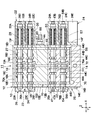
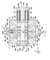
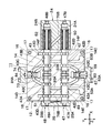
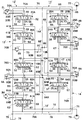
- FIG. 3 is a longitudinal sectional view of the multiple valve device as viewed in the direction of arrows IV-IV in FIG. 2;
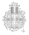
- FIG. 3 is a longitudinal cross-sectional view of the multiple valve device as viewed in the direction of arrows VV in FIG. 2;
- FIG. 3 is a longitudinal cross-sectional view of the multiple valve device as viewed in the direction of arrows VI-VI in FIG.
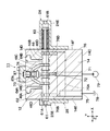
- FIG. 6 is a cross-sectional view of the first housing block together with a control valve for a bucket and a spare control valve as viewed in the direction of arrows VIII-VIII in FIG. 5;
- FIG. 6 is a cross-sectional view of the first housing block together with a relief valve as viewed in the direction of arrows IX-IX in FIG. 5;
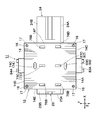
- FIG. 6 is a cross-sectional view of a second housing block together with a boom control valve as viewed in the direction of arrows XX in FIG. 5;
- FIG. 6 is a cross-sectional view of the second housing block together with a control valve for an arm, as viewed in the direction of arrows XI-XI in FIG. 5; It is the cross-sectional view which saw the 2nd housing block with the control valve for revolutions, and was seen from the arrow XII-XII direction in FIG.
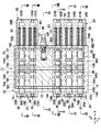
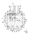
- FIG. 6 is a cross-sectional view of the second housing block as viewed from the direction of arrows XIII-XIII in FIG. 5 at the position of the mating surface.
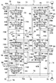
- It is a hydraulic circuit diagram of the multiple valve apparatus used for the hydraulic shovel shown in FIG. It is a hydraulic circuit figure of the multiple valve apparatus by a comparative example.
- FIG. 6 is a hydraulic circuit diagram of a multiple valve device according to a second embodiment.
- a total of four spool sliding holes are provided in the first housing block as a representative example of the multiple valve device, and a total of five spool slidings are provided in the second housing block.
- the case where a hole is provided is mentioned as an example.
- the multiple valve device according to the present invention is not limited to this, and among the valve housing provided with 6 to 12 spool slide holes, three to six in the first housing block are provided. It is also possible to provide a spool sliding hole and to provide three to six spool sliding holes in the second housing block.
- FIGS. 1 to 14 show a multiple valve device according to a first embodiment of the present invention.
- reference numeral 1 denotes a hydraulic shovel as a construction machine, and the hydraulic shovel 1 is rotatably mounted on a crawler type lower traveling body 2 capable of self-propelled movement and the lower traveling body 2 as shown in FIG. It comprises the upper revolving superstructure 3 and a working device 7 described later.
- the upper swing body 3 of the hydraulic shovel 1 constitutes a vehicle body of a construction machine together with the lower traveling body 2.
- the upper swing body 3 has a swing frame 3A which is swing-driven on the lower traveling body 2, and a cab 4, which will be described later, a counterweight 5, and a building cover 6 are provided on the swing frame 3A.
- the cab 4 is disposed on the front left side of the swing frame 3A.
- the cab 4 is formed as a substantially rectangular box, and defines a cab inside.
- a control lever for operation and a travel lever are provided inside the cab 4, in addition to the driver's seat on which the operator is seated.
- the counterweight 5 is provided on the rear end side of the swing frame 3A.
- the counterweight 5 is detachably mounted on the rear end side of the swing frame 3A, and balances the weight of the entire upper swing body 3 with respect to the work device 7 on the front side.
- a building cover 6 described later that accommodates an engine (not shown) is provided on the front side of the counterweight 5.
- the building cover 6 is located between the cab 4 and the counterweight 5 and is erected on the swing frame 3A.
- the building cover 6 is formed using, for example, a plurality of metal panels made of thin steel plates, and defines a machine room (not shown) for housing the engine therein.
- hydraulic pumps 77 and 79 (see FIG. 14) described later, which are rotationally driven by the engine, are provided.
- a multiple valve device 11 described later is provided at a position near the cab 4.
- the working device 7 is provided at the front of the upper swing body 3 so as to be capable of raising and lowering.
- the work device 7 has, for example, an excavating operation of earth and sand, with a boom 8 attached to the pivot frame 3A so as to be capable of raising and lowering the base end side, and an arm 9 attached to the tip end side of the boom 8 so as to be raised and lowered.
- a bucket 10 as a work tool rotatably provided on the tip end side of the arm 9 is configured.
- the boom 8 of the working device 7 is raised and lowered up and down with respect to the turning frame 3A by the boom cylinder 8A, and the arm 9 is raised and lowered up and down by the arm cylinder 9A on the tip end side of the boom 8.
- the bucket 10 as a work implement is pivoted up and down by a bucket cylinder 10A as a work implement cylinder on the tip end side of the arm 9.
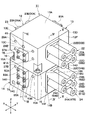
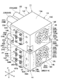
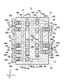
- the multiple valve device 11 includes a valve housing 12, spools 27, 31, 35, 39, 49, 51, 56, 58, 62 and a relief valve 88 described later. It consists of As shown in FIGS. 2 to 6, the valve housing 12 of the multiple valve device 11 is divided into two by a first housing block 13 and a second housing block 14 described later.
- first housing block 13 and the second housing block 14 are in the left and right directions (X-axis direction in FIG. 2) parallel to the mating surfaces 13B and 14A described later and in the front and rear directions (Y It is formed as a rectangular block extending in the axial direction and also extending upward and downward (in the Z-axis direction) perpendicular to the mating surfaces 13B and 14A.
- the first housing block 13 and the second housing block 14 are detachably engaged with each other at the position of the mating surfaces 13B and 14A.
- Reference numeral 13 denotes a first housing block which is a half of the valve housing 12, and the first housing block 13 is formed as a rectangular parallelepiped cast product as shown in FIGS. There is.
- the first housing block 13 has a total of six, including an upper surface 13A (hereinafter referred to as the upper surface 13A), a lower mating surface 13B, front and rear side surfaces 13C and 13D, and left and right side surfaces 13E and 13F. It has a face.
- a pump port 65 described later is provided in the first housing block 13 at a position above the cover 81A described later among the side surfaces 13C on the front side.
- pressure oil supply and discharge ports 29A and 29B and pressure oil supply and discharge ports 37A and 37B which will be described later, are respectively opened at positions separated in the left and right directions (X axis direction).
- the rear side surface 13D is opened at positions separated in the left and right directions (X-axis direction) respectively, and pressure oil supply and discharge ports 33A, 33B and pressure oil supply and discharge ports described later are provided. 41A and 41B are provided.
- a second housing block 14 constitutes another half of the valve housing 12.
- the second housing block 14 is also molded as a rectangular block (casting) by casting means.
- the second housing block 14 has a total of six pieces including an upper mating surface 14A, a lower other surface 14B (hereinafter referred to as a lower surface 14B), front and rear side surfaces 14C and 14D and left and right side surfaces 14E and 14F. Have a face.
- a pump port 71 described later is provided in the second housing block 14 at a position below the cover 85A described later among the side surfaces 14C on the front side.
- a tank port 75 described later is provided so as to be open at a position on the left side in the X-axis direction more than that.
- Pressure oil supply and discharge ports 53A and 53B which will be described later, are provided separately on the front side surface 14C in the left and right directions (X-axis direction).
- pressure oil supply and discharge ports 60A and 60B and pressure oil supply and discharge ports 64A and 64B which will be described later, are spaced apart in the left and right directions (X-axis direction) on the rear side 14D. It is provided.
- a plurality of (for example, a total of four) recessed portions 15 are formed. Recesses 15 are located at positions above the mating surface 13B at four corners of the first housing block 13 (ie, front and rear side surfaces 13C and 13D and left and right side surfaces). 13E and 13F are provided at the corners). Each recessed portion 15 is formed by cutting out the corner portion in an L-shaped cross section.
- a seating surface portion 15A for bolt fastening is formed between the mating surface 13B and the lower surface side of each recessed portion 15.
- These seat portions 15A constitute a fastening portion for fixing (connecting) the first housing block 13 to the second housing block 14 in a state of abutment with each other using a plurality of bolts 16.
- the recessed portion 15 forms a bolt mounting space for the bolt 16 at the upper position of the seat portion 15A.
- the seat portion 15A (fastening portion) of each recessed portion 15 is provided at a position closer to the mating surface 13B than each spool valve including the bucket control valve 34 and the spare control valve 38. That is, the seat portion 15A constituting the fastening portion is disposed at a position between the spool valve and the mating surface 13B.
- Screw holes 17 are formed in the second housing block 14 at positions facing the seating surface portions 15A at the top and bottom in the mating surface 14A. Bolts 16 are screwed into these screw holes 17, respectively. Thereby, the first housing block 13 and the second housing block 14 are fixed in an abutting state by using a total of four bolts 16 to constitute the valve housing 12 of the multiple valve device 11 .
- Reference numerals 18, 19, 20 and 21 denote four spool slide holes provided in the first housing block 13.
- the spool slide holes 18 to 21 are disposed in the first housing block 13 so as to have a three-dimensional structure similar to a cover 22 (see FIG. 2) described later. As shown in FIG. 4, FIG. 5, FIG. 7, and FIG. 8, the spool sliding holes 18 to 21 extend parallel to each other along the X axis direction, and are spaced apart from each other in the Y axis direction and Z axis direction. There is.
- the number of spool sliding holes provided in the first housing block 13 is not limited to four, and three spool sliding holes may be provided as a minimum so as to form a three-dimensional structure.
- the first housing block 13 is provided with, for example, a total of three spool slide holes 18, 19 and 20 for the travel control valves 26 and 30 and the bucket control valve 34 described later, for example.
- the spool sliding hole 21 may be omitted.
- the spool sliding holes 18 and 19 extend in parallel in the X axis direction as shown in FIG. 7, and are arranged at a predetermined interval in the Y axis direction.
- the spool slide holes 20 and 21 also extend in parallel in the X axis direction as shown in FIG. 8 and are arranged at a predetermined interval in the Y axis direction.
- the spool slide holes 18 and 20 extend parallel to each other along the X-axis direction as shown in FIG. 4 and are arranged at predetermined intervals in the Z-axis direction.
- the spool slide holes 19 and 21 also extend parallel to each other along the X axis direction, and are arranged at a predetermined interval in the Z axis direction.
- annular oil grooves 18A and 18B are formed axially spaced apart on the peripheral wall side of the spool sliding hole 18, and the oil grooves 18A and 18B are formed.
- Other annular oil grooves 18C and 18C are formed between them.
- another oil groove 18D, 18D is formed at a position that is axially outside the oil groove 18A, 18B.
- the oil grooves 18A to 18D become oil grooves on the pressure oil supply and discharge side and communicate with pressure oil supply and discharge ports 29A and 29B for traveling right described later, and the actuator side oil passage Is what constitutes
- Each oil groove 18C becomes an oil groove on the high pressure side and is in communication with a pump passage 66 and a high pressure passage 68, 69 on the pump port 65 side described later.
- Each oil groove 18D is an oil groove on the low pressure side and is in communication with a side passage 70B of a low pressure passage 70 on the side of a tank 78 described later.
- These oil grooves 18C and 18D constitute an oil pressure source side oil passage.
- oil grooves 19A and 19B on the pressure oil supply / discharge side constituting the actuator side oil passage and oil grooves on the high pressure side on the peripheral wall side of the spool sliding hole 19.
- the oil grooves 19C and 19C and the oil grooves 19D and 19D on the low pressure side are formed to be separated from each other in the axial direction.
- These oil grooves 19C and 19D constitute an oil pressure source side oil passage.
- 20C, 20C, and oil grooves 20D, 20D on the low pressure side are formed to be axially separated from each other.
- the oil grooves 21D and 21D are formed separately from each other in the axial direction.
- the cover body 22 is provided on the side surface 13F of the first housing block 13. As shown in FIG. 2, the cover 22 has a total of four cylindrical projections 22A, 22B, 22C, 22D, and these cylindrical projections 22A to 22D are control valves 26, 30 described later. , 34, and 38 constitute the hydraulic pilot units 26B, 30B, 34B, and 38B.
- the cylindrical projections 22A, 22B, 22C, 22D are coaxial with the spool slide holes 18, 19, 20, 21 and the side surfaces of the housing block 13. It projects from 13F in the X-axis direction. That is, the cylindrical protrusions 22A to 22D extend in parallel to each other along the X-axis direction in the same manner as the spool sliding holes 18 to 21, and are arranged in an arrangement relationship of three-dimensional structure mutually separated in the Y-axis direction and the Z-axis direction. It is set up.
- Another cover body 23 is provided on the side surface 13 E of the first housing block 13. As shown in FIG. 3, the other cover body 23 has a total of four short cylindrical parts 23A, 23B, 23C, and 23D. These cylindrical portions 23A to 23D constitute hydraulic pilot portions 26A, 30A, 34A, 38A of control valves 26, 30, 34, 38 described later.
- the cover body 24 is provided on the side surface 14F of the second housing block 14. As shown in FIG. 2, the cover body 24 has a total of five cylindrical protrusions 24A, 24B, 24C, 24D, 24E. These cylindrical projections 24A to 24E constitute hydraulic pilot parts 47B, 48B, 54B, 55B, 61B of control valves 47, 48, 54, 55, 61 described later.
- the cylindrical protrusions 24A, 24B, 24C, 24D, 24E are coaxial with the spool slide holes 42, 43, 44, 45 and 46 described later. And projects from the side surface 14F of the housing block 14 in the X-axis direction. That is, similar to the spool sliding holes 42 to 46, the cylindrical protrusions 24A to 24E extend in parallel to each other along the X axis direction, and are arranged in an arrangement relationship of three-dimensional structure separated from each other in the Y axis direction and Z axis direction. It is set up.
- Another cover 25 is provided on the side surface 14E of the second housing block 14. As shown in FIG. 3, the other cover body 25 has a total of five short cylindrical parts 25A, 25B, 25C, 25D, 25E. These cylindrical portions 25A to 25E constitute hydraulic pilot portions 47A, 48A, 54A, 55A, 61A of control valves 47, 48, 54, 55, 51 described later.
- Reference numeral 26 denotes a direction control valve for travel right (hereinafter referred to as travel control valve 26) provided in the first housing block 13.
- the travel control valve 26 is constituted by a spool valve formed by inserting the spool 27 into the spool sliding hole 18.
- the travel control valve 26 is located on both sides in the axial direction of the spool 27 and has left and right hydraulic pilot parts 26A and 26B in the cover bodies 22 and 23.
- the right side hydraulic pilot portion 26B is provided with a spring 28 which always biases the spool 27 toward the neutral position.
- a pilot pressure is supplied to the hydraulic pressure pilot parts 26A, 26B of the travel control valve 26 from an operation valve (not shown) of the travel lever.
- the spool 27 of the travel control valve 26 axially displaces the spool sliding hole 18 in accordance with the pilot pressure, and the oil grooves 18A and 18B on the actuator side are selectively selected relative to the oil grooves 18C and 18D on the hydraulic pressure source side. Connect and shut off. As a result, the traveling control valve 26 switches from the neutral position (A) in FIG. 14 to the left and right switching positions (B) and (C).
- the pressure oil supply and discharge ports 29A and 29B are provided on the side surface 13C of the first housing block 13. As shown in FIG. 7, these pressure oil supply and discharge ports 29A and 29B are in communication with the oil grooves 18A and 18B on the actuator side, and open on the other side 13C of the first housing block 13 (see FIG. See Figure 2). As shown in FIG. 14, the pressure oil supply and discharge ports 29A and 29B are provided with pressure oil discharged from a hydraulic pump 77 described later on the lower traveling body 2 (see FIG. 1) for left and right traveling motors 2L and 2R. For example, it supplies the driving motor 2R on the right side.
- Reference numeral 30 denotes a traveling left direction control valve (hereinafter referred to as a traveling control valve 30) provided in the first housing block 13.
- the travel control valve 30 is constituted by a spool valve formed by inserting the spool 31 into the spool sliding hole 19.
- the travel control valve 30 is located on both sides of the spool 31 in the axial direction, and has left and right hydraulic pilot parts 30A, 30B in the cover bodies 22, 23.
- the hydraulic pilot portion 30B is provided with a spring 32 which always biases the spool 31 toward the neutral position.
- a pilot pressure is supplied to the hydraulic pressure pilot sections 30A and 30B of the travel control valve 30 from an operation valve (not shown) of the travel lever.
- the spool 31 of the travel control valve 30 axially displaces the inside of the spool sliding hole 19 according to the pilot pressure, and the oil grooves 19A and 19B on the actuator side are selectively selected relative to the oil grooves 19C and 19D on the hydraulic source side. Communicate with and shut off. As a result, the traveling control valve 30 is switched from the neutral position (A) in FIG. 14 to the left and right switching positions (B) and (C).
- the other pressure oil supply and discharge ports 33A, 33B are provided on the side surface 13D of the first housing block 13. As shown in FIG. 7, the other pressure oil supply and discharge ports 33A and 33B communicate with the oil grooves 19A and 19B on the actuator side on one side, and open on the other side 13D of the first housing block 13 ( See Figure 3). As shown in FIG. 14, the pressure oil supply and discharge ports 33A and 33B are provided, for example, in the left and right traveling motors 2L and 2R for providing the lower traveling body 2 with pressure oil discharged from a hydraulic pump 79 described later. It supplies the driving motor 2L on the left side.
- Reference numeral 34 denotes a direction control valve for work tools (hereinafter referred to as a bucket control valve 34) provided in the first housing block 13.
- the bucket control valve 34 is constituted by a spool valve formed by inserting the spool 35 into the spool sliding hole 20.
- the bucket control valve 34 is provided with left and right hydraulic pilot parts 34A and 34B in the cover bodies 22 and 23 positioned on both sides of the spool 35 in the axial direction.
- the right side hydraulic pilot portion 34B is provided with a spring 36 which always biases the spool 35 toward the neutral position.
- a pilot pressure is supplied to the hydraulic pilot parts 34A and 34B of the bucket control valve 34 from a control valve (not shown) of the bucket control lever.
- the spool 35 of the bucket control valve 34 is axially displaced in the spool sliding hole 20 according to the pilot pressure, and the oil grooves 20A and 20B on the actuator side are selectively selected relative to the oil grooves 20C and 20D on the hydraulic source side. Communicate with and shut off.
- the bucket control valve 34 is switched from the neutral position (A) in FIG. 14 to the left and right switching positions (B) and (C).
- the pressure oil supply and discharge ports 37A and 37B are provided on the side surface 13C of the first housing block 13. As shown in FIG. 8, these pressure oil supply and discharge ports 37A and 37B communicate with the oil grooves 20A and 20B on the actuator side on one side, and open on the other side 13C of the first housing block 13 (see FIG. See Figure 2).
- the pressure oil supply and discharge ports 37A and 37B supply pressure oil to the bucket cylinder 10A (see FIG. 1) of the working device 7.
- Reference numeral 38 denotes a spare directional control valve (hereinafter referred to as spare control valve 38) provided in the first housing block 13.
- the spare control valve 38 is constituted by a spool valve formed by inserting the spool 39 into the spool sliding hole 21.
- Left and right hydraulic pilot sections 38A and 38B are provided in the cover bodies 22 and 23 on the both sides of the spool 39 in the axial direction of the spare control valve 38.
- the right side hydraulic pilot portion 38B is provided with a spring 40 for always biasing the spool 39 toward the neutral position.
- the hydraulic pilot parts 38A and 38B of the spare control valve 38 are supplied with pilot pressure from the operating valve (not shown) of the spare operating lever.
- the spool 39 of the spare control valve 38 is axially displaced in the spool sliding hole 21 according to the pilot pressure, and the oil grooves 21A and 21B on the actuator side are selectively selected relative to the oil grooves 21C and 21D on the hydraulic source side. Communicate with and shut off.
- the spare control valve 38 is switched from the neutral position (A) in FIG. 14 to the left and right switching positions (B) and (C).
- the other pressure oil supply and discharge ports 41A and 41B are provided on the side surface 13D of the first housing block 13. As shown in FIG. 8, these pressure oil supply and discharge ports 41A and 41B communicate with the oil grooves 21A and 21B on the actuator side on one side, and open on the other side 13D of the first housing block 13 (See Figure 3).
- the pressure oil supply and discharge ports 41A and 41B supply pressure oil to a spare hydraulic actuator (not shown).
- Reference numerals 42, 43, 44, 45 and 46 denote five spool slide holes provided in the second housing block 14.
- the spool slide holes 42 to 46 are disposed in the second housing block 14 in a three-dimensional structure corresponding to the cover body 24 (see FIG. 2). As shown in FIGS. 4, 5, and 10 to 12, the spool slide holes 42 to 46 extend parallel to each other along the X-axis direction, and are spaced apart from each other in the Y-axis direction and the Z-axis direction. There is.
- the number of spool sliding holes provided in the second housing block 14 is not limited to five, and three spool sliding holes may be provided as a minimum so as to form a three-dimensional structure.
- the second housing block 14 is provided with, for example, a total of three spool slide holes 42, 44 and 46 of the boom control valve 47, the arm control valve 54, and the turning control valve 61, and boom control
- the valve 48 and the spool slide holes 43 and 45 of the arm control valve 55 may be omitted.
- the spool sliding holes 42 and 43 extend in parallel in the X-axis direction and are arranged at a predetermined interval in the Y-axis direction.
- the spool sliding holes 45 and 46 extend in parallel in the X-axis direction, and are arranged at a predetermined interval in the Y-axis direction.
- the spool slide holes 42 and 44 extend parallel to each other along the X-axis direction and are spaced apart in the Z-axis direction.
- the spool sliding holes 45 are arranged between the spool sliding holes 43 and 46 in the Z-axis direction, and these spool sliding holes 43, 45 and 46 are X It extends parallel to each other along the axial direction.
- annular oil grooves 42A and 42B are formed in the second housing block 14 on the peripheral wall side of the spool sliding hole 42 so as to be axially separated.
- Other annular oil grooves 42C, 42C are formed between the oil grooves 42A, 42B.
- another oil groove 42D, 42D is formed at a position that is axially outside the oil grooves 42A, 42B.
- each oil groove 42C becomes an oil groove on the high pressure side and communicates with a high pressure passage 69 on the hydraulic pump 77 side described later, and each oil groove 42D becomes an oil groove on the low pressure side and the tank side described later It is in communication with the directional passage 76B.
- the oil groove 42C constitutes an oil pressure source side oil passage.
- oil grooves 43A, 43B on the pressure oil supply / discharge side constituting the actuator side oil passage on the peripheral wall side of the spool sliding hole 43, and oil on the high pressure side
- the grooves 43C and 43C, and the oil grooves 43D and 43D on the low pressure side are formed to be separated from each other in the axial direction.
- the oil groove 43C constitutes an oil pressure source side oil passage.
- oil grooves 44A and 44B on the pressure oil supply / discharge side constituting the actuator side oil passage, and a high pressure side oil groove constituting the hydraulic pressure source side oil passage are formed to be separated from each other in the axial direction.
- oil grooves 45A, 45B on the pressure oil supply / discharge side constituting the actuator side oil passage, oil grooves 45C, 45C on the high pressure side constituting the hydraulic pressure source side oil passage, low pressure side are formed to be separated from each other in the axial direction.
- oil grooves 46A, 46B on the pressure oil supply / discharge side constituting the actuator side oil passage oil grooves 46C, 46C on the high pressure side, low pressure
- oil grooves 46D, 46D on the side are formed axially separated from each other. These oil grooves 46C and 46D constitute a hydraulic pressure source side oil passage.
- Reference numerals 47 and 48 denote directional control valves for the boom provided on the second housing block 14 (hereinafter referred to as boom control valves 47 and 48).
- one of the boom control valves 47 and 48 is a spool valve formed by inserting the first boom spool 49 into the spool sliding hole 42. It is configured.
- the boom control valve 47 is located on both sides of the boom spool 49 in the axial direction, and has left and right hydraulic pilot parts 47A, 47B in the cover bodies 24, 25.
- the hydraulic pilot portion 47B on the right side is provided with a spring 50 for always biasing the boom spool 49 toward the neutral position.
- pilot pressure is supplied to the hydraulic pilot parts 47A and 47B of the boom control valve 47 from an operation valve (not shown) of the boom control lever.
- the boom spool 49 of the boom control valve 47 axially displaces the inside of the spool sliding hole 42 according to the pilot pressure, and the oil grooves 42A and 42B on the actuator side with respect to the oil grooves 42C and 42D on the hydraulic source side Selectively communicate and shut off.
- the boom control valve 47 switches from the neutral position (A) in FIG. 14 to the left and right switching positions (B) and (C).
- the other boom control valve 48 among the boom control valves 47 and 48 is constituted by a spool valve formed by inserting and fitting the second boom spool 51 into the spool sliding hole 43.
- the other boom control valve 48 is located axially on both sides of the boom spool 51 and has left and right hydraulic pilot parts 48A, 48B in the cover bodies 24, 25.
- the right side hydraulic pilot portion 48B is provided with a spring 52 for always biasing the boom spool 51 toward the neutral position.
- pilot pressure is supplied from the operation valve to the hydraulic pilot portions 48A and 48B of the boom control valve 48 in the same manner as the boom control valve 47 described above.
- the boom spool 51 of the boom control valve 48 axially displaces the inside of the spool sliding hole 43 in accordance with the pilot pressure, and the oil grooves 43A and 43B on the actuator side with respect to the oil grooves 43C and 43D on the hydraulic source side Selectively communicate and shut off. Thereby, the boom control valve 48 is switched from the neutral position (A) in FIG. 14 to the left and right switching positions (B) and (C).
- the pressure oil supply and discharge ports 53A and 53B are provided on the side surface 14C of the housing block 14. As shown in FIG. 10, these pressure oil supply and discharge ports 53A and 53B communicate with oil grooves 42A and 42B on one side on the actuator side and oil grooves 43A and 43B via joining passages 93A and 93B described later, The other side is open to the side surface 14C of the housing block 14 (see FIG. 2).
- the pressure oil supply and discharge ports 53A and 53B supply pressure oil to the boom cylinder 8A (see FIG. 1) of the working device 7.
- the boom control valves 47 and 48 cause the pressure oil discharged from the hydraulic pumps 77 and 79 described later to merge with each other in the second housing block 14 (merging passages 93A and 93B described later).
- the pressure oil joined at this time is supplied to the boom cylinder 8A of the working device 7 through the pressure oil supply and discharge ports 53A, 53B.
- the boom control valves 47 and 48 are in a relationship in which the pressure oil from the two hydraulic pumps 77 and 79 merge with each other. Therefore, the boom spools 49 and 51 of the boom control valves 47 and 48 are provided in the same second housing block 14.
- Reference numerals 54 and 55 denote direction control valves for the arm provided on the second housing block 14 (hereinafter referred to as arm control valves 54 and 55).
- arm control valves 54 and 55 As shown in FIG. 11, among the arm control valves 54 and 55, one arm control valve 54 is a spool valve formed by inserting and fitting the first arm spool 56 into the spool sliding hole 44. It is configured.
- the arm control valve 54 is located on both sides of the arm spool 56 in the axial direction, and has left and right hydraulic pilot parts 54A and 54B in the cover bodies 24 and 25.
- the right side hydraulic pilot section 54B is provided with a spring 57 for always biasing the arm spool 56 toward the neutral position.
- a pilot pressure is supplied to the hydraulic pressure pilot portions 54A and 54B of the arm control valve 54 from an operation valve (not shown) of the arm operation lever.
- the arm spool 56 of the arm control valve 54 axially displaces the inside of the spool sliding hole 44 according to the pilot pressure, and the oil grooves 44A and 44B on the actuator side with respect to the oil grooves 44C and 44D on the hydraulic source side Selectively communicate and shut off.
- the arm control valve 54 switches from the neutral position (A) in FIG. 14 to the left and right switching positions (B) and (C).
- the other arm control valve 55 among the arm control valves 54 and 55 is configured by a spool valve formed by inserting and fitting the second arm spool 58 into the spool sliding hole 45.
- the other arm control valve 55 is located on both sides in the axial direction of the arm spool 58, and has left and right hydraulic pilot parts 55A, 55B in the cover bodies 24, 25.
- the right side hydraulic pilot portion 55B is provided with a spring 59 for always biasing the arm spool 58 toward the neutral position.
- pilot pressure is supplied to the hydraulic pressure pilot parts 55A and 55B of the arm control valve 55 from the operation valve in the same manner as the arm control valve 54 described above.
- the arm spool 58 of the arm control valve 55 axially displaces the inside of the spool sliding hole 45 in accordance with the pilot pressure, and the oil grooves 45A and 45B on the actuator side with respect to the oil grooves 45C and 45D on the hydraulic source side Selectively communicate and shut off.
- the arm control valve 55 is switched from the neutral position (A) in FIG. 14 to the switching position (B), (C), and together with the arm control valve 54, the pressure oil supply and discharge port 60A, 60B side described later.
- the pressure oil supply and discharge ports 60A and 60B are provided on the side surface 14D of the housing block 14. As shown in FIG. 11, these pressure oil supply / discharge ports 60A, 60B communicate with the oil grooves 44A, 44B and the oil grooves 45A, 45B on the actuator side via merging passages 94A, 94B described later on one side, The other side is open to the side surface 14D of the housing block 14 (see FIG. 3).
- the pressure oil supply and discharge ports 60A and 60B supply pressure oil to the arm cylinder 9A (see FIG. 1) of the working device 7.
- the arm control valves 54 and 55 cause the pressure oil discharged from the hydraulic pumps 77 and 79 described later to merge with each other in the second housing block 14 (merging passages 94A and 94B described later).
- the pressure oil joined at this time is supplied to the arm cylinder 9A of the working device 7 through the pressure oil supply and discharge ports 60A and 60B.
- the arm control valves 54 and 55 are in a relationship in which the pressure oil from the two hydraulic pumps 77 and 79 merge with each other. Therefore, the arm spools 56 and 58 of the arm control valves 54 and 55 are provided in the same second housing block 14.
- Reference numeral 61 denotes a turning direction control valve (hereinafter referred to as a turning control valve 61) provided in the second housing block 14.
- the turning control valve 61 is constituted by a spool valve formed by inserting the spool 62 into the spool sliding hole 46.
- the turning control valve 61 is located on both sides in the axial direction of the spool 62 and has left and right hydraulic pilot parts 61A, 61B in the cover bodies 24, 25.
- the right side hydraulic pilot portion 61B is provided with a spring 63 for always urging the spool 62 toward the neutral position.
- a pilot pressure is supplied to the hydraulic pilot parts 61A and 61B of the turning control valve 61 from an operation valve (not shown) of the turning operation lever.
- the spool 62 of the swing control valve 61 axially displaces the inside of the spool sliding hole 46 according to the pilot pressure, and the oil grooves 46A and 46B on the actuator side are selectively selected relative to the oil grooves 46C and 46D on the hydraulic source side. Communicate with and shut off.
- the turning control valve 61 is switched from the neutral position (A) in FIG. 14 to the switching positions (B) and (C).
- the pressure oil supply and discharge ports 64A and 64B are provided on the side surface 14C of the housing block 14. As shown in FIG. 12, these pressure oil supply and discharge ports 64A, 64B are in communication with the oil grooves 46A, 46B on the actuator side, and are open at the side surface 14D of the housing block 14 (see FIG. 3). ). And as shown in FIG. 14, pressure oil supply / discharge ports 64A, 64B supply pressure oil to the turning motor 3M provided on the upper swing body 3 (see FIG. 1) side.
- first and second pump ports 65 and 71 a pump passage 66, a center bypass passage 67 and 73, high pressure passages 68, 69 and 74, and a low pressure passage 70 provided in the valve housing 12 of the multiple valve device 11.
- the tank port 75, the tank passage 76, the first and second hydraulic pumps 77 and 79, and the relief valve 88 will be described.
- the plurality of hydraulic pressure source side oil passages provided in the valve housing 12 of the multiple valve device 11 are, as described later, a first high pressure passage 69 to which pressure oil is supplied from the first hydraulic pump 77; And a second high pressure passage 74 to which pressure oil is supplied from the hydraulic pump 79 of FIG.
- the first high pressure passage 69 and the second high pressure passage 74 are disposed near the center side of the joint surfaces 13B and 14A surrounded by the recessed portions 15 of the valve housing 12.
- the first pump port 65 is provided on the side surface 13 C of the first housing block 13. As shown in FIG. 2, the first pump port 65 opens at the center of the side surface 13C at a position above the cover 81A described later and is connected to the discharge side of the hydraulic pump 77 described later. is there. The first pump port 65 opens at the side surface 13C of the first housing block 13 at a position close to the upper surface 13A opposite to the mating surface 13B with the spool slide holes 18, 19, 20, 21 interposed therebetween. Is provided. As shown in FIG. 6, the first pump port 65 communicates with the pump passage 66, the center bypass passage 67 and the high pressure passages 68 and 69 which are bored in the first housing block 13.
- the center bypass passage 67 and the high pressure passage 68 communicate with the first pump port 65 via the pump passage 66.
- the first high pressure passage 69 is a passage branched from the first passage 67A of the center bypass passage 67 between the travel control valve 26 and the bucket control valve 34. is there.
- the first high pressure passage 69 is disposed at a position closer to the side surface 13C of the housing block 13 than the first passage 67A of the center bypass passage 67 (see FIGS. 6, 8 and 9).
- the center bypass passage 67 and the first high pressure passage 69 are formed to extend upward and downward (Z-axis direction) from the first housing block 13 into the second housing block 14. ing.
- the center bypass passage 67 is formed in the first housing block 13 and extends upward and downward to a first passage 67A on the first pump side, and a second housing block 14 It includes a second passage 67B on the first pump side which is formed inside and extends downward, and a connection port 67C which causes the passages 67A and 67B to communicate with each other at the position of the mating surfaces 13B and 14A. There is.
- the connection ports 67C connect the first and second passages 67A and 67B of the center bypass passage 67 in a fluid-tight manner above and below the mating surfaces 13B and 14A (see FIG. 6).
- the first high pressure passage 69 is formed in the first housing block 13 and extends upward and downward, the first oil passage 69A on the first pump side, and the second housing block 14 is formed in the upper and lower directions.
- the connection port 69C connects the first and second oil passages 69A and 69B of the first high pressure passage 69 in a fluid-tight manner above and below the mating surfaces 13B and 14A.
- connection port 67C of the center bypass passage 67 and the connection port 69C of the first high pressure passage 69. 16 and the low pressure side oil passages are disposed closer to the center side of the mating surface 14A. That is, the connection port 67C of the center bypass passage 67 and the connection port 69C of the first high pressure passage 69 are disposed at positions closer to the center side of the mating surfaces 13B and 14A surrounded by the recessed portions 15 of the valve housing 12 It is done.
- the pump passage 66 and the first high pressure passage 69 use the pressure oil discharged from the first hydraulic pump 77 as the travel control valve 26, the bucket control valve 34, the boom control valve 47, and the arm control valve. It constitutes the high pressure side of the oil pressure source side oil passage which is supplied to the V. 54.
- the first oil passage 69A of the first high-pressure passage 69 branches between the traveling control valve 26 and the bucket control valve 34 from the first passage 67A of the center bypass passage 67.
- the downstream side extends to the position of the connection port 69C. That is, the first oil passage 69A of the first high pressure passage 69 constitutes a first oil passage on the first pump side.
- An upstream side of the second oil passage 69B of the first high pressure passage 69 communicates with the connection port 69C between the mating surfaces 13B and 14A, and a downstream side is connected in parallel to the boom control valve 47 and the arm control valve 54.
- the second oil passage 69B of the first high pressure passage 69 constitutes a second oil passage on the first pump side.
- the first oil passage 69A of the first high pressure passage 69 is located upstream of the bucket control valve 34 (spool 35) disposed at a position close to the mating surface 13B of the first housing block 13.
- the pressure oil from the first hydraulic pump 77 is supplied to the second oil passage 69B and the control valves 47 and 54 (spools 49 and 56) through the connection port 69C between the mating surfaces 13B and 14A.
- the low pressure passage 70 is formed in the first housing block 13. As shown in FIGS. 4 to 9, the low pressure passage 70 is formed at a position separated from the pump passage 66, the center bypass passage 67, and the high pressure passages 68 and 69.
- the low pressure passage 70 has a plurality of (two) upper passages 70A extending along the upper surface 13A of the first housing block 13 and an upper end side in communication with the respective upper passages 70A and the left and right of the first housing block 13 It is configured to include left and right side passages 70B extending downward along the side surfaces 13E and 13F.
- each side passage 70B of the low pressure passage 70 communicates with each side passage 76B of a tank passage 76 described later at the position of the mating surface 13B. Therefore, the oil (return oil from each hydraulic actuator) flowing in the upper passage 70A and the side passage 70B of the low pressure passage 70 is discharged to the tank 78 described later via the tank passage 76.
- the second pump port 71 is provided on the side surface 14 C of the second housing block 14. As shown in FIG. 2, the second pump port 71 opens at the center of the side surface 14C at a position below the cover 85A described later, and is connected to the discharge side of a second hydraulic pump 79 described later It is The second pump port 71 is disposed on the side surface 14C of the second housing block 14 at a position close to the lower surface 14B opposite to the mating surface 14A with the respective spool slide holes 42, 43, 44, 45 and 46 interposed therebetween. It is provided open. The second pump port 71 communicates with the pump passage 72 bored in the second housing block 14 and also communicates with the center bypass passage 73 and the second high pressure passage 74. The center bypass passage 73 and the second high pressure passage 74 are formed to extend in the Z-axis direction from the second housing block 14 to the first housing block 13.
- the second high pressure passage 74 branches from the pump passage 72 at a position upstream of the turning control valve 61, and at this branch position, the center bypass passage 73 is a pump passage. Connected to 72. As shown in FIG. 6, the second high pressure passage 74 is disposed closer to the side surfaces 13 D and 14 D of the housing blocks 13 and 14 than the center bypass passage 73. The center bypass passage 73 and the second high pressure passage 74 are formed to extend upward from the second housing block 14 into the first housing block 13.
- the center bypass passage 73 is formed in the first housing block 13 and extends upward and downward to a first passage 73A on the second pump side, and a second housing block 14 It includes a second passage 73B on the second pump side, which is formed inside and extends downward, and a connection port 73C which causes the passages 73A and 73B to communicate with each other at the position of the mating surfaces 13B and 14A. There is.
- the connection ports 73C connect the first and second passages 73A and 73B of the center bypass passage 73 in a fluid-tight manner above and below the mating surfaces 13B and 14A (see FIG. 6).
- a second high pressure passage 74 connected to the second hydraulic pump 79 is formed in the first housing block 13 and extends upward and downward, a first oil passage 74A on the second pump side, and a second oil passage 74A.
- the second pump-side second oil passage 74B formed in the housing block 14 and extending downward is communicated with the first and second oil passages 74A and 74B at the position of the mating surfaces 13B and 14A.
- a connection port 74C is connected to the first and second oil passages 74A and 74B of the second high pressure passage 74 in a fluid-tight manner above and below the mating surfaces 13B and 14A.
- connection port 73C of the center bypass passage 73 and the connection port 74C of the high pressure passage 74 are provided with four bolts 16 and a low voltage provided at four corners of the second housing block 14.
- the side oil passages i.e., the side passages 70B of the low pressure passage 70 and the side passages 76B of the tank passage 76 described later
- the connection port 73C of the center bypass passage 73 and the connection port 74C of the second high pressure passage 74 are disposed at positions closer to the center side of the mating surfaces 13B and 14A surrounded by the recessed portions 15 of the valve housing 12 It is done.
- the pump passage 72 and the second high pressure passage 74 are configured to control the pressure oil discharged from the second hydraulic pump 79 described later, the turning control valve 61, the arm control valve 55, the boom control valve 48, and the spare control valve. 38, the high pressure side of the hydraulic pressure source side oil passage supplied to the traveling control valve 30 and the like.
- the first oil passage 74A of the second high pressure passage 74 has its upstream side in communication with the connection port 74C between the mating surfaces 13B and 14A, and its downstream side is connected in parallel to the spare control valve 38 and the traveling control valve 30 There is. That is, the first oil passage 74A on the second pump side supplies the pressure oil from the second hydraulic pump 79 to the spool 39 of the control valve 38 and the spool 31 of the control valve 30.
- the second oil passage 74 B on the second pump side of the second high pressure passage 74 is located upstream of the turning control valve 61 (a position upstream of the control valve 61). It branches from the second passage 73B of the center bypass passage 73, and the downstream side extends to the position of the connection port 74C.
- the second oil passage 74B on the second pump side is connected in parallel to the arm control valve 55 and the boom control valve 48, and supplies pressure oil from the second hydraulic pump 79 to the spools 58 and 51. .
- the high pressure sides of the plurality of hydraulic pressure source side oil passages provided in the first housing block 13 are the first oil passage 69A on the first pump side connected to the first hydraulic pump 77, and the second It is formed separately from the first oil passage 74A on the second pump side connected to the hydraulic pump 79.
- the high pressure side of the plurality of hydraulic pressure source side oil passages provided in the second housing block 14 is a second oil passage 69B on the first pump side connected to the first hydraulic pump 77, and the second hydraulic pressure It is formed separately from the second oil passage 74B on the second pump side connected to the pump 79.
- the first oil passage 69A on the first pump side formed in the first housing block 13 is connected to the second oil passage 69B on the first pump side formed in the second housing block 14 between the mating surfaces 13B and 14A. It communicates through the connection port 69C.
- the first oil passage 74A on the second pump side formed in the first housing block 13 is connected to the second oil passage 74B on the second pump side formed in the second housing block 14 between the mating surfaces 13B and 14A. It communicates through the connection port 74C.
- the tank port 75 is provided on the side surface 14 C of the second housing block 14. As shown in FIG. 2, the tank port 75 opens to the side surface 14C at a position separated leftward from the second pump port 71, and is connected to a tank 78 described later. As shown in FIGS. 12 and 14, the tank passage 76 as a low pressure passage has a lower passage 76A and left and right side passages 76B. The tank port 75 communicates with the left and right side passages 76B via the lower passage 76A of the tank passage 76, and the oil (return oil from each hydraulic actuator) flowing in these side passages 76B is tanked It will be discharged at 78.
- the side passages 76B are formed in the second housing block 14 so as to be widely separated in the left and right (X-axis direction).
- the side passage 76B is fluid-tightly connected to the side passage 70B of the low pressure passage 70 formed in the first housing block 13 at the position of the mating surfaces 13B and 14A. Since the oil (return oil) flowing between the side passages 70B and 76B has a low pressure, oil leaks hardly occur at the positions of the joint surfaces 13B and 14A.
- Reference numeral 77 denotes a first hydraulic pump which constitutes a first hydraulic source together with the tank 78. As shown in FIGS. 6 and 7, the discharge side of the first hydraulic pump 77 is connected to the first pump port 65, and the control valve 26, 34 is connected via the pump passage 66 and the first high pressure passage 69. , 47, 54 (spools 27, 35, 49, 56) are supplied with pressure oil.
- Reference numeral 79 denotes a second hydraulic pump which constitutes a second hydraulic source together with the tank 78. As shown in FIGS. 6 and 12, the discharge side of the second hydraulic pump 79 is connected to the second pump port 71, and the control valves 61 and 55 are connected via the pump passage 72 and the second high pressure passage 74. , 48, 38, 30 (spools 62, 58, 51, 39, 31) are supplied with pressure oil.
- the check valve 80 is attached to the travel control valve 30. As shown in FIG. 7, the check valve 80 is mounted so as to be charged from the side surface 13D of the housing block 13 toward the high pressure passage 74, and the cover 80A closes the space between the side surface 13D.
- the check valve 80 allows the pressure oil to flow from the high pressure passage 74 toward the oil groove 19C, and prevents reverse flow.
- the check valve 81 is attached to the bucket control valve 34. As shown in FIG. 8, the check valve 81 is attached so as to be charged from the side surface 13C of the housing block 13 toward the high pressure passage 69, and a cover 81A is closed between the check valve 81 and the side surface 13C.
- the check valve 81 allows the pressure oil to flow from the high pressure passage 69 toward the oil groove 20C, and prevents reverse flow.
- Another check valve 82 is attached to the spare control valve 38.
- the other check valve 82 is configured substantially the same as the check valve 80 described above, and a cover 82A is provided on the side surface 13D side of the housing block 13.
- the check valve 82 allows the pressure oil to flow from the high pressure passage 74 toward the oil groove 21C, and prevents reverse flow.
- the second housing block 14 is also provided with check valves 83 to 87.
- the check valve 83 is attached to the boom control valve 47, and the check valve 84 is attached to the boom control valve 48.
- These check valves 83 and 84 are provided with covers 83A and 84A, respectively.
- the check valve 85 is attached to the arm control valve 54, and the check valve 86 is attached to the arm control valve 55.
- These check valves 85 and 86 are provided with covers 85A and 86A, respectively.
- the check valve 87 is attached to the turning control valve 61, and the check valve 87 has a cover 87A.
- the relief valve 88 is a main relief valve provided in the first housing block 13;
- the relief valve 88 suppresses the maximum pressure of the pressure oil discharged from the first hydraulic pump 77 and the second hydraulic pump 79 to a predetermined pressure or lower.
- the relief valve 88 is attached to the first housing block 13 so as to be located between the pair of check valves 89 and 90.
- the check valve 89 is normally urged in the valve closing direction by the valve spring 89A so as to close the relief passage 91 communicating with the high pressure passage 68.
- the check valve 89 opens.
- the pressure in the high pressure passage 68 is introduced to the pressure chamber 88A of the relief valve 88 via the relief passage 91.
- check valve 89 prevents fluid from flowing from pressure chamber 88A toward relief passage 91.
- the check valve 90 is always urged in the valve closing direction by the valve spring 90A so as to close the relief passage 92 communicating with the high pressure passage 74.
- the check valve 90 opens.
- the pressure in the high pressure passage 74 is introduced to the pressure chamber 88A of the relief valve 88 through the relief passage 92.
- the check valve 90 prevents the fluid from flowing from the pressure chamber 88A to the relief passage 92 side.
- the relief valve 88 opens when the pressure in the pressure chamber 88A (that is, the high pressure passages 68 and 74) exceeds a predetermined relief setting pressure, and the excess pressure at this time is made via the side passage 70B of the low pressure passage 70. Relieve the tank 78 side. Thereby, the relief valve 88 is set to the highest pressure in the pump passages 66 and 72 and the high pressure passages 68, 69 and 74 (ie, the highest pressure oil discharged from the first hydraulic pump 77 and the second hydraulic pump 79). (Pressure) is kept below a predetermined relief set pressure.
- the relief valve 88 is disposed at a position near the mating surface 13B of the housing block 13 below the spare control valve 38 (spool slide hole 21). That is, the relief valve 88 is disposed at a position closer to the mating surface 13 B than the spool sliding holes 18 to 21 provided in the housing block 13. As a result, as shown in FIG. 14, the relief valve 88 can be positioned approximately midway between the first pump port 65 and the second pump port 71 (ie, the pipe lengths between the two can be made approximately equal). Position).
- the merging passages 93A, 93B are provided in the second housing block 14 between the boom control valves 47, 48. As shown in FIG. 10, these merging passages 93A and 93B are oil grooves 42A and 42B of the boom control valve 47 (spool slide hole 42) and oil grooves 43A of the boom control valve 48 (spool slide hole 43). , 43B are always communicated.
- the merging passages 93A, 93B, together with the oil grooves 42A, 42B and the oil grooves 43A, 43B, constitute an actuator-side oil passage of the boom control valves 47, 48.
- the merging passages 93A and 93B merge the pressure oil supplied from the first and second hydraulic pumps 77 and 79 to the boom control valves 47 and 48 (boom spools 49 and 51), and merge the combined pressure oil.
- the boom cylinder 8A of the working device 7 is supplied from the pressure oil supply and discharge ports 53A, 53B.
- the merging passages 94A, 94B are provided between the arm control valves 54, 55 in the second housing block 14. As shown in FIG. 11, these merging passages 94A, 94B are provided with oil grooves 44A, 44B of the arm control valve 54 (spool slide hole 44) and oil grooves 45A of the arm control valve 55 (spool slide hole 45). , 45B are always communicated.
- the merging passages 94A, 94B, together with the oil grooves 44A, 44B and the oil grooves 45A, 45B, constitute an actuator-side oil passage of the arm control valves 54, 55.
- the merging passages 94A and 94B merge pressure oil supplied from the first and second hydraulic pumps 77 and 79 to the arm control valves 54 and 55 (arm spools 56 and 58), and combine the pressure oil
- the pressure oil supply and discharge ports 60A and 60B are supplied to the arm cylinder 9A of the working device 7.
- the multiple valve device 11 mounted on the hydraulic shovel 1 according to the present embodiment has the configuration as described above, and its operation will be described next.
- the traveling control valve 26 on the right side supplies pressure oil from the first hydraulic pump 77 to the traveling motor 2R on the right side via the pressure oil supply and discharge ports 29A and 29B.
- the traveling control valve 30 on the left side supplies pressure oil from the second hydraulic pump 79 to the traveling motor 2L on the left side via the pressure oil supply / discharge ports 33A and 33B.
- the undercarriage 2 can drive the crawler belt with the left and right traveling motors 2L and 2R to perform a traveling operation to move the vehicle forward or backward.
- the bucket 10 When the earth and sand is excavated at the work site, the bucket 10 is turned while raising and lowering the boom 8 and the arm 9 of the working device 7 up and down. That is, when the operator in the cab 4 tilts the bucket control lever, the bucket control valve 34 is switched from the neutral position (A) to either of the switching positions (B) and (C). Therefore, the pressure oil from the first hydraulic pump 77 is supplied to the bucket cylinder 10A via the bucket control valve 34 and the pressure oil supply / discharge ports 37A and 37B.
- the boom control valves 47 and 48 are switched from the neutral position (A) to either of the switching positions (B) and (C).
- the pressure oil discharged from the first and second hydraulic pumps 77 and 79 are joined together by the boom control valves 47 and 48 via the merging passages 93A and 93B, and the joined pressure oil is pressurized oil.
- the boom cylinder 8A can be supplied via the supply / discharge ports 53A, 53B.
- the arm control valves 54 and 55 are switched from the neutral position (A) to either of the switching positions (B) and (C).
- the pressure oil discharged from the first and second hydraulic pumps 77 and 79 are joined together by the arm control valves 54 and 55 via the joining passages 94A and 94B, and the joined pressure oil is pressurized oil.
- the arm cylinder 9A can be supplied via the supply / discharge ports 60A, 60B.
- the switching control valve 61 when the upper swing body 3 is driven to turn on the lower traveling body 2, either of the switching control valve 61 from the neutral position (A) to the switching position (B) or (C) according to the tilting operation of the turning operation lever. Switch to heels.
- the pressure oil discharged from the second hydraulic pump 79 can be supplied to the turning motor 3M through the turning control valve 61 and the pressure oil supply / discharge ports 64A and 64B, and the turning motor 3M is driven to turn be able to.
- the left housing block divided into two in the left and right directions (for example, Y axis direction) 13 ', right housing block 14' may be used.
- the left housing block 13 'and the right housing block 14' shown in FIG. 15 are detachably engaged with each other, for example, at the positions of mating surfaces 13B 'and 14A' extending in the upper and lower directions (Z-axis direction).
- the merging passages 93A and 93B are divided into two at the positions of the mating surfaces 13B 'and 14A', and the two are communicated by the connection ports 93A 'and 93B'.
- the merging passages 94A and 94B are divided into two at the positions of the mating surfaces 13B 'and 14A', respectively, and the two are communicated by the connection ports 94A 'and 94B'.
- connection ports 93A ', 93B', 94A ', 94B' are formed at the positions of the mating surfaces 13B ', 14A' of the housing blocks 13 ', 14'.
- a connection port 68 ' is formed at the position of the mating surfaces 13B' and 14A 'on the downstream side of the check valve 89. Ru.
- a connection port 72 ' is formed at the position of the mating surfaces 13B' and 14A '.
- connection ports 68 ', 72 are provided at the positions of the mating surfaces 13B', 14A 'interposed between the left housing block 13' and the right housing block 14 '. ', 93A', 93B ', 94A', 94B 'are formed.
- the number of oil pressure merging points on the mating surfaces 13B 'and 14A' increases to six, which increases the possibility of oil leakage.
- the valve housing 12 of the multiple valve device 11 is moved upward and downward (for example, in the Z-axis direction) to the first housing block 13 and the first
- the two housing blocks 14 are formed to be divided into two.
- the first housing block 13 and the second housing block 14 are configured to be abutted and separated from each other at the positions of the mating surfaces 13B and 14A that face each other in the upper and lower directions.
- connection ports 67C, 69C, 73C, 74C are provided at the positions of the mating surfaces 13B, 14A between the first housing block 13 and the second housing block 14. You only have to set it.
- the pressure oil from the first and second hydraulic pumps 77 and 79 can be controlled by all the control valves 26, 30, 34, 38, 47, 48, 54, 55, 61 (spools 27, 31, 35, 39, 49, 51, 56, 58, 62).
- the number of connection ports 67C, 69C, 73C, 74C can be reduced to the minimum necessary, and the occurrence of oil leakage between the mating surfaces 13B, 14A can be suppressed.
- the pressure oil from the first hydraulic pump 77 is controlled via the first passage 67A of the center bypass passage 67 and the first oil passage 69A on the first pump side of the high pressure passage 69 in the first housing block 13 26, 34 (spools 27, 35) can be supplied.
- the pressure oil from the first hydraulic pump 77 is supplied to the second oil passage 69B on the first pump side of the second housing block 14 through the connection port 69C of the mating surfaces 13B and 14A, and the second housing block 14 Control valves 47, 54 (spools 49, 56) can be supplied.
- the pressure oil from the second hydraulic pump 79 passes through the second passage 73 B of the center bypass passage 73 and the second oil passage 74 B on the second pump side of the high pressure passage 74, and the control valve 61 in the second housing block 14. , 55, 48 (spools 62, 58, 51). Moreover, the pressure oil from the second hydraulic pump 79 is also supplied to the first oil passage 74A on the second pump side of the first housing block 13 through the connection port 74C of the mating surfaces 13B and 14A, and the control valves 38 and 30 are provided. (Spool 39, 31) can be supplied.
- boom control valves 47 and 48 boost spools 49 and 51 for controlling the boom cylinder 8A are provided in the same second housing block 14. For this reason, the pressure oil discharged from the first and second hydraulic pumps 77 and 79 are merged in one second housing block 14 (merging passages 93A and 93B) to be provided on the two boom spools 49 and 51. Can be supplied. As a result, it is not necessary to provide the merging passages 93A, 93B at positions sandwiching the mating surfaces 13B, 14A of the two housing blocks 13, 14. On the other hand, in the comparative example shown in FIG. 15, for example, the connection ports 93A 'and 93B' of the merging paths 93A and 93B are provided at the positions of the mating surfaces 13B 'and 14A' of the housing blocks 13 'and 14'. The number is increasing.
- the number of connection ports in the mating surfaces 13B and 14A can be reduced, and the occurrence of oil leakage can be suppressed.
- the arm control valves 54 and 55 (arm spools 56 and 58) for controlling the arm cylinder 9A are also provided in the same second housing block 14.
- the pressure oil discharged from the first and second hydraulic pumps 77 and 79 are merged in one second housing block 14 (merging passages 94A and 94B) to the two arm spools 56 and 58. It can be supplied and the number of connection ports can be reduced.
- first housing block 13 is provided with respective recessed portions 15 each of which forms a seating surface portion 15A for bolt fastening between the mating surface 13B and the first housing block 13.
- each recessed portion 15 can be utilized as a bolt mounting space.
- the first housing block 13 and the second housing block 14 can be fixed in an abutting state, and the valve housing 12 of the multiple valve device 11 can be easily assembled.
- each bolt 16 is a position inside the corner side of the mating surfaces 13B and 14A of the housing blocks 13 and 14.
- the fastening positions of the bolts 16 are positions effective to suppress the occurrence of oil leakage from the mating surfaces 13B and 14A.
- the recessed portions 15 are not provided on the four corners of the first housing block 13, it will be necessary to fasten the two housing blocks using a long bolt. Moreover, in this case, the inner spool sliding hole is easily deformed by the tightening force of the long bolt.
- the recessed portions 15 are provided at the four corners of the first housing block 13, and a plurality of short bolts 16 are fastened to the seat surface portion 15A. Thereby, the deformation of the spool slide holes 18, 19, 20, 21, 42, 43, 44, 45, 46 in the housing blocks 13, 14 can be suppressed. As a result, the slidability of the spools 27, 31, 35, 39, 49, 51, 56, 58, 62 can be maintained favorably.
- a total of four spool slide holes 18 to 21 extend parallel to each other along the X-axis direction while being separated from each other in the Y-axis direction and the Z-axis direction.
- a relief valve 88 can be disposed which suppresses the maximum pressure in the pump passage 66 and the first and second high pressure passages 69 and 74 to a predetermined set pressure or less.
- the second housing block 14 for example, a total of five spool slide holes 42 to 46 are separated from each other in the Y-axis direction and the Z-axis direction and extend parallel to each other in the X-axis direction. It can be arranged with a three-dimensional structure. As a result, the boom control valves 47 and 48, the arm control valves 54 and 55, and the turning control valve 61 can be assembled in a compact structure on the second housing block 14 side.
- the bearing surface portions 15A of the four recessed portions 15 have four fastening portions for securing the first housing block 13 and the second housing block 14 in an abutting state by using four bolts 16 Configured.
- the high-pressure oil passages i.e., connection ports 67C, 69C, 73C, 74C
- connection ports 67C, 69C, 73C, 74C passing through the positions of the mating surfaces 13B, 14A are the same as those of the mating surfaces 13B, 14A surrounded by the recessed portions 15 of the valve housing 12. It is located at the center side.
- connection ports 67C, 69C, 73C, and 74C have four fastening portions (seating surface portion 15A, that is, bolts 16) and low pressure side oil passages (ie, respective side passages 70B of the low pressure passage 70 and the tank passage 76). It is disposed closer to the central side of the mating surfaces 13B and 14A than the side passage 76B).
- the two housing blocks 13 and 14 can be fastened using four bolts 16 in a state where the housing blocks 13 and 14 are abutted at the position of the mating surfaces 13B and 14A, and the connecting ports 67C, 69C, 73C and 74C can be mating surfaces. It can be disposed at a position closer to the center side of 13B and 14A.
- the connection ports 67C, 69C, 73C, 74C are separated from the fastening position of each bolt 16 and the low pressure side oil passage (i.e., each side passage 70B of the low pressure passage 70 and each side passage 76B of the tank passage 76). It can be placed at the center position.
- the pressure oil flowing through the connection ports 67C, 69C, 73C, 74C can be prevented from leaking to the outside from the position of the mating surfaces 13B, 14A.
- the area of 14A can be reduced.
- the number of high pressure passages 69 and 74 passing between the mating surfaces 13B and 14A, the number of center bypass passages 67 and 73, etc. are shown in the comparative example shown in FIG. It can be reliably reduced.
- the spool slide holes 18 to 21 and 42 to 46 can be disposed in a compact manner by forming a three-dimensional structure in the first housing block 13 and the second housing block 14. Therefore, the size and weight of the entire valve housing 12 can be reduced as compared with the conventional two-split type, and the handling and the workability at the time of transfer and transfer can be improved.
- the structure of the mold used to cast the first housing block 13 and the second housing block 14 can be simplified, and in particular, the structure of the core can be simplified. Work can be easily performed.
- the working time involved in the molding process at the time of casting can be shortened, and the workability and productivity can be improved.
- a relief valve 88 is provided at a position closer to the mating surface 13B than the spool slide holes 18 to 21. For this reason, among the plurality of pump passages 66 and 72 and high pressure passages 69 and 74 formed in the first housing block 13 and the second housing block 14, for example, approximately between the two hydraulic pumps 77 and 79.
- the relief valve 88 can be placed at the following position (i.e., near the mating surfaces 13B, 14A) to set the maximum pressure in the conduit.
- FIG. 16 shows a second embodiment of the present invention.
- a feature of the present embodiment is that the first and second hydraulic pumps are both connected to a hydraulic pressure source side oil passage provided in one housing block.
- the same components as those in the first embodiment described above are denoted by the same reference numerals, and the description thereof will be omitted.
- reference numeral 100 denotes a second hydraulic pump employed in the second embodiment.
- the second hydraulic pump 100 constitutes a second hydraulic source together with the tank 78.
- the discharge side of the second hydraulic pump 100 is connected to the second pump port 101 described later, and the control valves 30, 38, 48, 55 are connected via the pump passage 102 and the second high pressure passage 103.
- 61 is supplied with pressure oil.
- Reference numeral 101 denotes a second pump port provided in the first housing block 13.
- the second pump port 101 is connected to the discharge side of the second hydraulic pump 100 instead of the second pump port 71 described in the first embodiment.
- the second pump port 101 communicates with a pump passage 102 bored in the first housing block 13. Further, the second pump port 101 is also in communication with the second high pressure passage 103 and the center bypass passage 104.
- the second high pressure passage 103 and the center bypass passage 104 are formed to extend, for example, upward and downward from the first housing block 13 to the second housing block 14.
- the second pump port 101 and the pump passage 102 are formed in the first housing block 13 so as to be separated from the first pump port 65 and the pump passage 66 in the left and right directions.
- the second high pressure passage 103 and the center bypass passage 104 are also formed to be spaced apart from the center bypass passage 67 and the first high pressure passage 69 in the left and right directions.
- the second high pressure passage 103 branches off from the pump passage 102 at a position upstream of the turning control valve 61.
- Pressure oil from the second hydraulic pump 100 i.e., the pump passage 102 is supplied to the turning control valve 61 through the center bypass passage 104 branched from the second high pressure passage 103. Furthermore, this pressure oil is also supplied to the arm control valve 55, the boom control valve 48, the spare control valve 38, and the travel control valve 30.
- the second high pressure passage 103 is formed in the first housing block 13 and extends upward and downward, the first oil passage 103A on the second pump side, and the second oil passage 103 is formed in the second housing block 14 Comprising a second oil passage 103B on the second pump side extending in the direction, and a connection port 103C which causes the first and second oil passages 103A and 103B to communicate with each other at the position of the mating surfaces 13B and 14A There is.
- the connection port 103C By the connection port 103C, the oil passages 103A and 103B of the second high pressure passage 103 are fluid-tightly connected above and below the mating surfaces 13B and 14A.
- the center bypass passage 104 is formed in the first housing block 13 and extends upward and downward in a first passage 104A on the second pump side, and is formed in the second housing block 14 in the upper and lower directions.
- a connection port 104C for communicating between the passages 104A and 104B at the position of the mating surfaces 13B and 14A.
- the connection ports 104C connect the passages 104A and 104B of the center bypass passage 104 in a fluid-tight manner above and below the mating surfaces 13B and 14A.
- the second passage 104 B of the center bypass passage 104 is connected to the second oil passage 103 B of the high pressure passage 103 in the second housing block 14.
- the pressure oil discharged from the second hydraulic pump 100 is introduced from the second oil passage 103 B side of the high pressure passage 103 into the second passage 104 B of the center bypass passage 104.
- the pressure oil discharged from the second hydraulic pump 100 is transferred from the second passage 104B of the center bypass passage 104 to the mating surface 13B. , 14A into the first passage 104A via the connection port 104C. Thereafter, the pressure oil becomes return oil, and is discharged from the tank passage 76 to the tank 78 via the upper passage 70A and the side passage 70B of the low pressure passage 70.
- the pump passage 102 and the second high pressure passage 103 are configured to transfer the pressure oil discharged from the second hydraulic pump 100 to the travel control valve 30, the spare control valve 38, the boom control valve 48, the arm control valve 55,
- the high pressure side of the hydraulic pressure source side oil passage supplied to the turning control valve 61 and the like is configured.
- the first oil passage 103A on the second pump side of the second high pressure passage 103 is connected in parallel to the traveling control valve 30 and the spare control valve 38.
- the first oil passage 103A supplies pressure oil from the second hydraulic pump 100 to the traveling control valve 30 (spool 31) and the spare control valve 38 (spool 39), and this first oil passage
- the downstream side of 103A communicates with the connection port 103C between the mating surfaces 13B and 14A.
- the upstream side of the second oil passage 103B on the second pump side of the second high pressure passage 103 is in communication with the connection port 103C between the mating surfaces 13B and 14A.
- the second oil passage 103B has its downstream side connected in parallel to the boom control valve 48, the arm control valve 55, and the turning control valve 61.
- the second oil passage 103B is a second hydraulic pump.
- the pressure oil from 100 is supplied to the boom control valve 48 (spool 51), the arm control valve 55 (spool 58), and the turning control valve 61 (spool 62).
- the first oil passage 69A on the first pump side formed in the first housing block 13 is connected to the second oil passage 69B on the first pump side formed in the second housing block 14 between the mating surfaces 13B and 14A. It communicates through the connection port 69C.
- the first oil passage 103A on the second pump side formed in the first housing block 13 is connected to the second oil passage 103B on the second pump side formed in the second housing block 14 between the mating surfaces 13B and 14A. It communicates through the connection port 103C.
- the pressure oil from the second hydraulic pump 100 is transferred to the control valves 30, 38 (spools 31, 39) in the first housing block 13 as the second pump. It can be supplied via the side first oil passage 103A. Furthermore, the pressure oil from the second hydraulic pump 100 can be supplied to the second oil passage 103B on the second pump side of the second housing block 14 through the connection port 103C between the mating surfaces 13B and 14A. Therefore, the same effect as that of the first embodiment can be obtained.
- connection ports 67C, 69C, 103C and 104C at the positions of the mating surfaces 13B and 14A between the first housing block 13 and the second housing block 14.
- the pressure oil from the first and second hydraulic pumps 77 and 100 can be controlled by all the control valves 26, 30, 34, 38, 47, 48, 54, 55 and 61 (spools 27, 31, 35, 39, 49, 51, 56, 58, 62). That is, the number of connection ports 67C, 69C, 103C and 104C can be reduced to the necessary minimum, and the occurrence of oil leakage between the mating surfaces 13B and 14A can be suppressed.
- the first housing block 13 is provided with left and right travel control valves 26, 30, a bucket control valve 34 and a spare control valve 38, and the second housing block 14 is provided.
- the boom control valves 47 and 48, the arm control valves 54 and 55, and the turning control valve 61 are provided.
- the present invention is not limited to this.
- the first housing block 13 is provided with two boom control valves, two arm control valves, and one pivoting control valve. It is good also as composition provided with a control valve for run left, a control valve for run right, a control valve for buckets, a control valve of spare, etc. in 14.
- the first housing block 13 is provided with a minimum number of three spool slide holes (for example, a total of three spool slide holes for a boom control valve, an arm control valve, and a turning control valve)
- the second housing block 14 also has three spool slide holes (for example, a total of three spool slide holes for the travel left control valve, the travel right control valve, and the bucket control valve) as the minimum number. It may be provided.
- the first housing block is provided with 3 to 6 spool slide holes
- the second housing block is provided.
- three to six spool slide holes may be provided.
- one of the first and second housing blocks may be provided with a multiple valve device as to which of the first and second housing blocks these control valves (a plurality of control valves consisting of 6 to 12 spool slide holes) are provided. It may be appropriately changed in relation to the hydraulic excavator (construction machine) to be used or the other hydraulic working machine.
- the first housing block is provided with three to six spool slide holes so as to have a three-dimensional structure
- the second housing block is provided with three to six other three-dimensional structures. It suffices to provide a spool sliding hole.
- the construction machine on which the multiple valve device of the present invention is mounted is not limited to a hydraulic shovel, but can be applied to, for example, a wheel type hydraulic shovel, a hydraulic crane, a wheel loader, a bulldozer, or a work vehicle called a lift truck. Furthermore, it can be applied to hydraulic devices other than construction machines.
Landscapes
- Engineering & Computer Science (AREA)
- General Engineering & Computer Science (AREA)
- Mechanical Engineering (AREA)
- Physics & Mathematics (AREA)
- Fluid Mechanics (AREA)
- Valve Housings (AREA)
- Fluid-Pressure Circuits (AREA)
Abstract
L'invention porte sur un boîtier de valve (12), qui est divisé au niveau des positions de surfaces de liaison (13B, 14A) en deux parties, c'est-à-dire en un premier bloc de boîtier (13) et un second bloc de boîtier (14). Le premier bloc de boîtier (13) présente un premier passage d'huile côté première pompe (69A) relié à une première pompe hydraulique (77) et est aussi muni d'un premier passage d'huile côté seconde pompe (74A) relié à une seconde pompe hydraulique (79). Le second bloc de boîtier (14) est muni d'un second passage d'huile côté première pompe (69B) relié à la première pompe hydraulique (77) et est aussi muni d'un second passage d'huile côté seconde pompe (74B) relié à la seconde pompe hydraulique (79). Le premier passage d'huile (69A) est relié au second passage d'huile (69B) à travers les surfaces de liaison (13B, 14A). Le premier passage d'huile (74A) est relié au second passage d'huile (74B) à travers les surfaces de liaison (13B, 14A).
Priority Applications (1)
| Application Number | Priority Date | Filing Date | Title |
|---|---|---|---|
| KR20147025688A KR20150018767A (ko) | 2012-05-31 | 2013-05-22 | 다연 밸브 장치 |
Applications Claiming Priority (2)
| Application Number | Priority Date | Filing Date | Title |
|---|---|---|---|
| JP2012125125A JP2013249897A (ja) | 2012-05-31 | 2012-05-31 | 多連弁装置 |
| JP2012-125125 | 2012-05-31 |
Publications (1)
| Publication Number | Publication Date |
|---|---|
| WO2013179969A1 true WO2013179969A1 (fr) | 2013-12-05 |
Family
ID=49673170
Family Applications (1)
| Application Number | Title | Priority Date | Filing Date |
|---|---|---|---|
| PCT/JP2013/064206 WO2013179969A1 (fr) | 2012-05-31 | 2013-05-22 | Dispositif à valves multiples |
Country Status (3)
| Country | Link |
|---|---|
| JP (1) | JP2013249897A (fr) |
| KR (1) | KR20150018767A (fr) |
| WO (1) | WO2013179969A1 (fr) |
Cited By (2)
| Publication number | Priority date | Publication date | Assignee | Title |
|---|---|---|---|---|
| CN107939764A (zh) * | 2017-12-18 | 2018-04-20 | 徐工集团工程机械有限公司 | 液压阀组和钻机 |
| CN108138810A (zh) * | 2015-10-08 | 2018-06-08 | 沃尔沃建筑设备公司 | 滑阀 |
Families Citing this family (2)
| Publication number | Priority date | Publication date | Assignee | Title |
|---|---|---|---|---|
| DE112015006286T5 (de) | 2015-03-11 | 2018-01-11 | Kyb Corporation | Fluiddrucksteuervorrichtung |
| JP6889674B2 (ja) * | 2018-03-09 | 2021-06-18 | Kyb株式会社 | 制御弁 |
Citations (4)
| Publication number | Priority date | Publication date | Assignee | Title |
|---|---|---|---|---|
| JPS5474918U (fr) * | 1977-11-08 | 1979-05-28 | ||
| JPS59186502U (ja) * | 1983-05-31 | 1984-12-11 | 株式会社小松製作所 | 方向切換弁 |
| JP2001355601A (ja) * | 2000-06-15 | 2001-12-26 | Hitachi Constr Mach Co Ltd | コントロールバルブ |
| JP2011112123A (ja) * | 2009-11-25 | 2011-06-09 | Kawasaki Precision Machinery Ltd | マルチコントロール弁装置、及びそのケーシング |
-
2012
- 2012-05-31 JP JP2012125125A patent/JP2013249897A/ja active Pending
-
2013
- 2013-05-22 WO PCT/JP2013/064206 patent/WO2013179969A1/fr active Application Filing
- 2013-05-22 KR KR20147025688A patent/KR20150018767A/ko not_active Application Discontinuation
Patent Citations (4)
| Publication number | Priority date | Publication date | Assignee | Title |
|---|---|---|---|---|
| JPS5474918U (fr) * | 1977-11-08 | 1979-05-28 | ||
| JPS59186502U (ja) * | 1983-05-31 | 1984-12-11 | 株式会社小松製作所 | 方向切換弁 |
| JP2001355601A (ja) * | 2000-06-15 | 2001-12-26 | Hitachi Constr Mach Co Ltd | コントロールバルブ |
| JP2011112123A (ja) * | 2009-11-25 | 2011-06-09 | Kawasaki Precision Machinery Ltd | マルチコントロール弁装置、及びそのケーシング |
Cited By (6)
| Publication number | Priority date | Publication date | Assignee | Title |
|---|---|---|---|---|
| CN108138810A (zh) * | 2015-10-08 | 2018-06-08 | 沃尔沃建筑设备公司 | 滑阀 |
| US20180298587A1 (en) * | 2015-10-08 | 2018-10-18 | Volvo Construction Equipment Ab | Spool valve |
| EP3361105A4 (fr) * | 2015-10-08 | 2019-05-15 | Volvo Construction Equipment AB | Distributeur à tiroirs |
| US10633829B2 (en) | 2015-10-08 | 2020-04-28 | Volvo Construction Equipment Ab | Spool valve |
| CN107939764A (zh) * | 2017-12-18 | 2018-04-20 | 徐工集团工程机械有限公司 | 液压阀组和钻机 |
| CN107939764B (zh) * | 2017-12-18 | 2024-02-02 | 江苏徐工工程机械研究院有限公司 | 液压阀组和钻机 |
Also Published As
| Publication number | Publication date |
|---|---|
| JP2013249897A (ja) | 2013-12-12 |
| KR20150018767A (ko) | 2015-02-24 |
Similar Documents
| Publication | Publication Date | Title |
|---|---|---|
| JP5809602B2 (ja) | 多連弁装置 | |
| JP5985276B2 (ja) | 建設機械の油圧回路及びその制御装置 | |
| US9821840B2 (en) | Hydraulic control device and construction machinery including same | |
| US10969026B2 (en) | Valve device | |
| WO2013179969A1 (fr) | Dispositif à valves multiples | |
| WO2013141037A1 (fr) | Vanne de commande de translation | |
| JP3929411B2 (ja) | 一体構造本体を有するマルチプル油圧スプールバルブアセンブリ | |
| JP6964052B2 (ja) | 建設機械の油圧回路 | |
| JP7121642B2 (ja) | 流体圧制御装置 | |
| US5701796A (en) | Hydraulic apparatus for traveling | |
| JP4963337B2 (ja) | 建設機械の多連方向切換弁 | |
| JP6453820B2 (ja) | 建設機械用方向制御弁グループ | |
| WO2018173843A1 (fr) | Soupape multisoupape de commande directionnelle | |
| JP6505630B2 (ja) | 方向制御弁 | |
| JP7121641B2 (ja) | 流体圧制御装置 | |
| JP2002013656A (ja) | 油圧作業機械用多連弁 | |
| JP7379307B2 (ja) | 作業機の油圧システム | |
| JP6763006B2 (ja) | ショベル及び建設機械用方向制御弁グループ | |
| JPH08170353A (ja) | 多連式方向切換弁 | |
| JP6682396B2 (ja) | ショベル | |
| JP2022075402A (ja) | 液圧駆動システム | |
| JPH0630909Y2 (ja) | アウトリガ用多重チェック弁装置 | |
| KR20240036101A (ko) | 유량 제어 밸브 | |
| JP2023082487A (ja) | 油圧システムおよび作業車両 | |
| JPH11270504A (ja) | 油圧回路 |
Legal Events
| Date | Code | Title | Description |
|---|---|---|---|
| 121 | Ep: the epo has been informed by wipo that ep was designated in this application |
Ref document number: 13797291 Country of ref document: EP Kind code of ref document: A1 |
|
| ENP | Entry into the national phase |
Ref document number: 20147025688 Country of ref document: KR Kind code of ref document: A |
|
| NENP | Non-entry into the national phase |
Ref country code: DE |
|
| 122 | Ep: pct application non-entry in european phase |
Ref document number: 13797291 Country of ref document: EP Kind code of ref document: A1 |