WO2013162001A1 - Mécanisme d'assistance pour porte - Google Patents
Mécanisme d'assistance pour porte Download PDFInfo
- Publication number
- WO2013162001A1 WO2013162001A1 PCT/JP2013/062398 JP2013062398W WO2013162001A1 WO 2013162001 A1 WO2013162001 A1 WO 2013162001A1 JP 2013062398 W JP2013062398 W JP 2013062398W WO 2013162001 A1 WO2013162001 A1 WO 2013162001A1
- Authority
- WO
- WIPO (PCT)
- Prior art keywords
- receiving member
- base body
- door
- door frame
- slider
- Prior art date
Links
Images


Classifications
-
- E—FIXED CONSTRUCTIONS
- E05—LOCKS; KEYS; WINDOW OR DOOR FITTINGS; SAFES
- E05F—DEVICES FOR MOVING WINGS INTO OPEN OR CLOSED POSITION; CHECKS FOR WINGS; WING FITTINGS NOT OTHERWISE PROVIDED FOR, CONCERNED WITH THE FUNCTIONING OF THE WING
- E05F5/00—Braking devices, e.g. checks; Stops; Buffers
- E05F5/02—Braking devices, e.g. checks; Stops; Buffers specially for preventing the slamming of swinging wings during final closing movement, e.g. jamb stops
-
- E—FIXED CONSTRUCTIONS
- E05—LOCKS; KEYS; WINDOW OR DOOR FITTINGS; SAFES
- E05F—DEVICES FOR MOVING WINGS INTO OPEN OR CLOSED POSITION; CHECKS FOR WINGS; WING FITTINGS NOT OTHERWISE PROVIDED FOR, CONCERNED WITH THE FUNCTIONING OF THE WING
- E05F1/00—Closers or openers for wings, not otherwise provided for in this subclass
- E05F1/08—Closers or openers for wings, not otherwise provided for in this subclass spring-actuated, e.g. for horizontally sliding wings
- E05F1/10—Closers or openers for wings, not otherwise provided for in this subclass spring-actuated, e.g. for horizontally sliding wings for swinging wings, e.g. counterbalance
- E05F1/1008—Closers or openers for wings, not otherwise provided for in this subclass spring-actuated, e.g. for horizontally sliding wings for swinging wings, e.g. counterbalance with a coil spring parallel with the pivot axis
- E05F1/1025—Closers or openers for wings, not otherwise provided for in this subclass spring-actuated, e.g. for horizontally sliding wings for swinging wings, e.g. counterbalance with a coil spring parallel with the pivot axis with a compression or traction spring
-
- E—FIXED CONSTRUCTIONS
- E05—LOCKS; KEYS; WINDOW OR DOOR FITTINGS; SAFES
- E05F—DEVICES FOR MOVING WINGS INTO OPEN OR CLOSED POSITION; CHECKS FOR WINGS; WING FITTINGS NOT OTHERWISE PROVIDED FOR, CONCERNED WITH THE FUNCTIONING OF THE WING
- E05F5/00—Braking devices, e.g. checks; Stops; Buffers
- E05F5/02—Braking devices, e.g. checks; Stops; Buffers specially for preventing the slamming of swinging wings during final closing movement, e.g. jamb stops
- E05F5/027—Braking devices, e.g. checks; Stops; Buffers specially for preventing the slamming of swinging wings during final closing movement, e.g. jamb stops with closing action
-
- E—FIXED CONSTRUCTIONS
- E05—LOCKS; KEYS; WINDOW OR DOOR FITTINGS; SAFES
- E05Y—INDEXING SCHEME RELATING TO HINGES OR OTHER SUSPENSION DEVICES FOR DOORS, WINDOWS OR WINGS AND DEVICES FOR MOVING WINGS INTO OPEN OR CLOSED POSITION, CHECKS FOR WINGS AND WING FITTINGS NOT OTHERWISE PROVIDED FOR, CONCERNED WITH THE FUNCTIONING OF THE WING
- E05Y2201/00—Constructional elements; Accessories therefore
- E05Y2201/20—Brakes; Disengaging means, e.g. clutches; Holders, e.g. locks; Stops; Accessories therefore
- E05Y2201/21—Brakes
-
- E—FIXED CONSTRUCTIONS
- E05—LOCKS; KEYS; WINDOW OR DOOR FITTINGS; SAFES
- E05Y—INDEXING SCHEME RELATING TO HINGES OR OTHER SUSPENSION DEVICES FOR DOORS, WINDOWS OR WINGS AND DEVICES FOR MOVING WINGS INTO OPEN OR CLOSED POSITION, CHECKS FOR WINGS AND WING FITTINGS NOT OTHERWISE PROVIDED FOR, CONCERNED WITH THE FUNCTIONING OF THE WING
- E05Y2201/00—Constructional elements; Accessories therefore
- E05Y2201/20—Brakes; Disengaging means, e.g. clutches; Holders, e.g. locks; Stops; Accessories therefore
- E05Y2201/252—Brakes; Disengaging means, e.g. clutches; Holders, e.g. locks; Stops; Accessories therefore characterised by type of friction
- E05Y2201/254—Fluid or viscous friction
- E05Y2201/256—Fluid or viscous friction with pistons or vanes
-
- E—FIXED CONSTRUCTIONS
- E05—LOCKS; KEYS; WINDOW OR DOOR FITTINGS; SAFES
- E05Y—INDEXING SCHEME RELATING TO HINGES OR OTHER SUSPENSION DEVICES FOR DOORS, WINDOWS OR WINGS AND DEVICES FOR MOVING WINGS INTO OPEN OR CLOSED POSITION, CHECKS FOR WINGS AND WING FITTINGS NOT OTHERWISE PROVIDED FOR, CONCERNED WITH THE FUNCTIONING OF THE WING
- E05Y2201/00—Constructional elements; Accessories therefore
- E05Y2201/20—Brakes; Disengaging means, e.g. clutches; Holders, e.g. locks; Stops; Accessories therefore
- E05Y2201/262—Brakes; Disengaging means, e.g. clutches; Holders, e.g. locks; Stops; Accessories therefore characterised by type of motion
- E05Y2201/264—Brakes; Disengaging means, e.g. clutches; Holders, e.g. locks; Stops; Accessories therefore characterised by type of motion linear
-
- E—FIXED CONSTRUCTIONS
- E05—LOCKS; KEYS; WINDOW OR DOOR FITTINGS; SAFES
- E05Y—INDEXING SCHEME RELATING TO HINGES OR OTHER SUSPENSION DEVICES FOR DOORS, WINDOWS OR WINGS AND DEVICES FOR MOVING WINGS INTO OPEN OR CLOSED POSITION, CHECKS FOR WINGS AND WING FITTINGS NOT OTHERWISE PROVIDED FOR, CONCERNED WITH THE FUNCTIONING OF THE WING
- E05Y2201/00—Constructional elements; Accessories therefore
- E05Y2201/40—Motors; Magnets; Springs; Weights; Accessories therefore
- E05Y2201/404—Motors; Magnets; Springs; Weights; Accessories therefore characterised by the function
- E05Y2201/41—Motors; Magnets; Springs; Weights; Accessories therefore characterised by the function for closing
- E05Y2201/412—Motors; Magnets; Springs; Weights; Accessories therefore characterised by the function for closing for the final closing movement
-
- E—FIXED CONSTRUCTIONS
- E05—LOCKS; KEYS; WINDOW OR DOOR FITTINGS; SAFES
- E05Y—INDEXING SCHEME RELATING TO HINGES OR OTHER SUSPENSION DEVICES FOR DOORS, WINDOWS OR WINGS AND DEVICES FOR MOVING WINGS INTO OPEN OR CLOSED POSITION, CHECKS FOR WINGS AND WING FITTINGS NOT OTHERWISE PROVIDED FOR, CONCERNED WITH THE FUNCTIONING OF THE WING
- E05Y2201/00—Constructional elements; Accessories therefore
- E05Y2201/40—Motors; Magnets; Springs; Weights; Accessories therefore
- E05Y2201/47—Springs; Spring tensioners
- E05Y2201/474—Compression springs
-
- E—FIXED CONSTRUCTIONS
- E05—LOCKS; KEYS; WINDOW OR DOOR FITTINGS; SAFES
- E05Y—INDEXING SCHEME RELATING TO HINGES OR OTHER SUSPENSION DEVICES FOR DOORS, WINDOWS OR WINGS AND DEVICES FOR MOVING WINGS INTO OPEN OR CLOSED POSITION, CHECKS FOR WINGS AND WING FITTINGS NOT OTHERWISE PROVIDED FOR, CONCERNED WITH THE FUNCTIONING OF THE WING
- E05Y2900/00—Application of doors, windows, wings or fittings thereof
- E05Y2900/10—Application of doors, windows, wings or fittings thereof for buildings or parts thereof
- E05Y2900/13—Application of doors, windows, wings or fittings thereof for buildings or parts thereof characterised by the type of wing
- E05Y2900/132—Doors
Definitions
- the present invention relates to a mechanism that operates when the door is moved forward to a predetermined position toward the closed position, and assists, that is, assists the forward movement of the door to the closed position.
- a catcher that catches the striker provided on the door side when the door reaches a predetermined position by the closing operation and forcibly rotates by the biasing means from there.
- the catcher is forcibly rotated by pressing a contact portion of a slider biased in a direction approaching the catcher against a contacted portion of the catcher.
- the main problem to be solved by the present invention is that the receiving member attached to the door frame side in this type of assist mechanism can be appropriately attached to the door frame without impairing the appearance of the upper part of the door frame. There is in point to do.
- the door assist mechanism is provided with a receiving member provided at the upper end of the door and an upper part of the door frame, and the door is moved forward toward the closed position.
- An assist mechanism comprising a receiving member that captures the received member at a predetermined position and assists the forward movement of the door,
- the receiving member is provided so as to be rotatable at a constant angle between the first position and the second position, and the receiving member is captured by the capturing unit or released from the captured member in the first position.
- the assist is made by turning to the second position from this capture state,
- a decorative cover for closing the engraving opening The size of the base body in the left-right direction of the door frame is smaller than the size of the engraving, and the threading portion of the base body has a long hole shape in the left-right direction of the door frame,
- the base body is provided with an engaging recess for an engaging claw provided on the decorative cover so as to have a length in the left-right direction of the door frame.
- the base body Since the dimension of the base body in the left-right direction of the door frame is smaller than the engraved dimension, and the threading portion of the screw has a long hole shape in the left-right direction of the door frame, the base body is It can be temporarily fixed to the engraved top surface with screws in a state of being movable in the left-right direction. In a state where the base body is temporarily fixed to the door frame, the door is moved forward toward the closed position, and the base body is moved and adjusted in the left-right direction to a position where the receiving member receives the receiving portion. Then, the base member is finally fixed to the door frame with screws, whereby the receiving member can be appropriately fixed to the door frame.
- the decorative cover closes the engraved open part by combining the engaging claw and the engaging recess with the base body, but the engaging claw engages with the engaging recess even if the base body is adjusted and moved by the length of the engaging recess. It is possible to make it.
- the receiving member is pivotally supported by a metal shaft having a shaft base fixed to a metal base. When it does in this way, the rigidity of the part to which this kinetic energy acts directly via the receiving member in a base body can be improved effectively.
- a slider that moves in conjunction with the rotation of the receiving member by linkage means on the side of the receiving member, and an urging force is applied to the rotating toward the second position of the receiving member via the slider.
- the base body may be configured to have a channel shape including a bottom plate portion provided with a shaft body and a pair of side plate portions that sandwich the slider and guide the movement of the slider. is there.
- the base body is provided with a metal cover body constructed between a pair of side plate portions of the base body so as to accommodate a part of the receiving member between the base plate portion and the base plate portion.
- the portion of the base body that receives the kinetic energy is shaped like a square tube, and the rigidity can be further increased.
- a sliding contact portion of the receiving member may be formed on the inner surface of the cover body.
- the door is supported at two positions of the sliding contact portion of the shaft body and the cover body, and the rotation is made without blurring.
- a slit is provided in the side plate portion of the base body along the moving direction of the slider, and the space between the slit and the tip of the side plate portion protrudes inward of the base body to form a rail portion for the slider.
- the slider can be guided without play by the side plate portion of the base body.
- the receiving member attached to the door frame side in this type of assist mechanism can be appropriately attached to the door frame without impairing the appearance of the upper part of the door frame.
- FIG. 1 is a perspective configuration diagram showing a use state of an assist mechanism according to an embodiment of the present invention as viewed obliquely from below.
- FIG. 2 is a perspective configuration diagram illustrating the usage state of the assist mechanism according to the embodiment as viewed obliquely from above.
- FIG. 3 is a bottom view showing a unit including a receiving member constituting the assist mechanism according to the embodiment.
- FIG. 4 is a bottom view of the unit of FIG. 3 with the cover body constituting the unit removed.
- FIG. 5 is a perspective view showing the unit of FIG. 3 with the cover body constituting the unit removed.
- FIG. 6 is a bottom view of the receiving member in the first position.
- FIG. 1 is a perspective configuration diagram showing a use state of an assist mechanism according to an embodiment of the present invention as viewed obliquely from below.
- FIG. 2 is a perspective configuration diagram illustrating the usage state of the assist mechanism according to the embodiment as viewed obliquely from above.
- FIG. 3 is
- FIG. 7 is a bottom configuration diagram showing a state in which the receiving member is in a position slightly rotated from the first position toward the second position to capture the received member.
- FIG. 8 is a bottom configuration diagram in a state where the receiving member is in the second position and the door is in the closed position. A part of the description of the door is omitted, and the outline of the received member is indicated by a two-dot chain line.
- FIG. 9 is an exploded perspective view of the receiving member.
- FIG. 10 is a perspective view of the upper part constituting the receiving member.
- FIG. 11 is a perspective view of a slider included in the unit of FIG. 12 is a perspective view of an additional slider included in the unit of FIG.
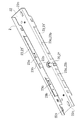
- FIG. 13 is a perspective view of a base body constituting the unit of FIG. FIG.
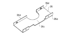
- FIG. 14 is a perspective view of a cover body constituting the unit of FIG.
- FIG. 15 is a perspective view of the cover body constituting the unit of FIG. 3, and shows the cover body from a different direction from FIG.
- FIG. 16 is a bottom view of a door frame provided with a carving for storing and mounting the unit of FIG. 3 and a door supported by the door frame.
- FIG. 17 is a bottom view showing a state in which the unit of FIG. 3 is housed in the engraving of FIG.
- FIG. 18 is a bottom view showing a state in which the engraving is closed with a decorative cover from the state of FIG.
- FIG. 19 is a perspective view of the decorative cover of FIG.
- the assist mechanism operates when the door is moved forward to a predetermined position toward the closed position, and functions to assist, that is, assist the forward movement of the door to the closed position. Is.
- the assist mechanism includes a receiving member 1 and a receiving member 7.
- the receiving member 1 assists the forward movement of the door D by capturing the received member 7 at a predetermined position when the door D is moved forward toward the closed position.
- the receiving member 7 is provided on the door D, and the receiving member 1 is provided on the door frame F that supports the receiving member 7 via the hinge Da.
- the receiving member 7 On the hinge Da side of the door D, the receiving member 7 has an engraving Dc opened upward on the upper end surface Db of the door D, and the upper surface of the receiving member 7 is substantially flush with the upper end surface Db of the door D. It is paid in this way.
- the received member 7 has a hook shape that allows a part of the receiving member 1 to enter the inside of the hook at a predetermined position when the door D is moved forward toward the reference position (closed position in the illustrated example).
- Part 70 In the illustrated example, such a hook-like portion 70 is formed by engraving a groove-like recess 72 on the upper surface portion of the disk-like body 71 that is received and fixed in the engraving Dc.
- the recess 72 has a groove rear end 73a positioned on the hinge Da side of the door D and extends in the left-right direction of the door D.
- the recess 72 communicates with the linear groove 73 and rotates the door D toward the closed position. It has an introduction groove 74 that is opened outward on the one surface Dd side of the door D that is positioned forward when it is moved.
- a hook-like portion 70 having a hook end directed toward the free end De of the door D is formed at a communication location between the linear groove portion 73 and the introduction groove portion 74.
- the introduction groove portion 74 is formed by inclining a groove wall 74a continuous with the groove wall 73b on the side facing the hook-shaped portion 70 in the linear groove portion 73 so as to approach the free end De of the door D toward the introduction opening.
- the guide surface 74b is used.
- a notch Df that communicates with the introduction opening of the introduction groove 74 is formed on the one surface Dd side of the door D.
- a catching portion 10 to be described later of the receiving member 1 has its axis lined up and down, and its lower end 10a is below the upper end surface Db of the door D and above the introduction groove portion 74 of the receiving member 7 and the groove bottom of the linear groove portion 73.
- the receiving member 1 has been rotated to the second position on the outside of the hook end of the hook-like portion 70 of the receiving member 7 without capturing the receiving member 7.
- a recess 75 in which the capturing part 10 is accommodated is formed at the reference position when the door D is moved forward from the (malfunction state).
- the hook end of the hook-like portion 70 is configured to be located inward from the outer edge 71a of the disk-like body 71 constituting the member 7 to be received.
- the recess 75 is formed between the ends.
- the receiving member 1 is rotated in the horizontal direction around the vertical axis 20 in the engraving Fc with the lower open surface formed in front of the door contact portion Fb on the hinge Da side of the door D in the upper portion Fb of the door frame F. It is prepared to be movable.
- the engraving Fc is a rectangular depression that is long in the left-right direction.
- the receiving member 1 is pivotally supported by a metal shaft body 21 as the vertical shaft 20 in which a shaft base portion is fixed to a metal base body 2.
- the base body 2 has a substantially rectangular bottom plate portion 22 having a length slightly smaller than the length of the engraving Fc (the dimension of the door frame F in the left-right direction x) and a width substantially equal to the width of the engraving Fc. And a pair of front and rear side plate portions 23, 23 so as to form a channel with an open bottom surface. (FIG. 13)
- the base body 2 is screwed to the top surface Fd of the engraving Fc.
- the threaded portion 22a of the screw J for screwing is provided at the left and right ends of the bottom plate portion 22 of the base body 2 at two front and rear positions, respectively.
- the through portions 22a of the screws J are each formed in a long hole shape that is long in the left-right direction x of the door frame F.
- the shaft body 21 has a head (not shown) at its upper end.
- the bottom plate portion 22 of the base body 2 has a through-hole 22b having a size that does not allow the head of the shaft body 21 to pass through at a position in the middle in the left-right direction.
- the shaft body 21 is inserted into the through-hole 22b until the head of the shaft body 21 is hooked on the outer surface of the base body 2, and then the head side of the shaft body 21 is caulked to the base. It is made to adhere to the body 2.
- the receiving member 1 is disposed in the center of the base body 2, and a slider 3 is disposed between the receiving member 1 and an end portion 24 of the door D positioned on the hinge Da side of the base body 2.
- An additional slider 5 is disposed between the base body 2 and the end 25 positioned on the free end De of the door D.
- a metal cover body is provided between the front and rear side plate portions 23 ′ and 23 ′′ of the base body 2 so that the receiving member 1 is accommodated between the base body 2 and the bottom plate portion 22 of the base body 2.
- the cover body 26 has a channel shape with an open top surface provided with rising portions 26a on the front and rear sides, and the side plate portion 23 of the base body 2.
- the base body 2 is fixed in the left-right direction by screwing the rising portion 26a of the cover body 26 to the corresponding side plate 23 of the base body 2 so that the lower end of the cover body 26 and the lower surface 26b of the cover body 26 are the same surface. Is covered with the cover body 26.
- the base body 2 combined with the cover body 26 is stored in the engraving Dc so that the lower surface 26b of the cover body 26 does not protrude from the lower surface of the upper portion Fb of the door frame F.
- the capturing part 10 of the receiving member 1 has its lower end 10 a positioned below the lower surface 26 b of the cover body 26.
- the unit configured by receiving the receiving member 1 and the like in the base body 2 moves the slider 3 and the additional slider 5 in the length direction thereof, and the urging means 4 in the direction along the length direction. Since the layout is such that the central axis of the compression coil spring 4 ′ and the central axis of the piston damper 60 serving as the braking means 6 are arranged, it can be installed on the upper part Fb of the door frame F without any trouble.
- the receiving member 1 is provided so as to be able to turn at a constant angle between the first position and the second position, and is spaced apart from each other in the direction around the turning center, so that the capturing portion of the received member 7 10, the control pin 11, and the linkage pin 12, and the captured member 7 is captured by the capturing unit 10 or the captured received member 7 is released at the first position.
- the assist is performed by turning the second position to the second position.
- the receiving member 1 rotates in the horizontal direction about the vertical shaft 20 fixed to the bottom plate portion 22 of the base body 2.
- the capturing unit 10, the control pin 11, and the linking pin 12 are all in the shape of an axis, and the axis is along the vertical direction.
- the distance from the vertical axis 20 is the largest in the capturing unit 10, and the distance between the control pin 11 and the vertical axis 20 is substantially equal to the distance between the linkage pin 12 and the vertical axis 20.
- the capturing part 10 is located in front of the front side plate part 23 'facing the one surface Dd of the door D in the base body 2 in the first position (FIGS. 1 and 6), and the base body 2 in the second position. It is located below. (Fig. 8)
- the control pin 11 and the linking pin 12 are both provided so as to protrude toward the bottom plate portion 22 side of the base body 2 and are always positioned in the base body 2.
- the control pin 11 is positioned on the hinge Da side of the door D, and the linkage pin 12 is always positioned on the free end side De of the door D.
- the receiving member 1 is configured by combining a lower part indicated by reference numeral 13 and an upper part indicated by reference numeral 14 in FIG.
- the lower part 13 has a fan-shaped part 13a and an arm part 13b protruding in a horizontal direction from the essential position of the fan-shaped part 13a, and the capturing part 10 is formed at the tip of the arm part 13b.
- the upper part 14 has a fan-like shape in which the fan-shaped part 13a of the lower part 13 is attached to the lower surface, and has a boss part 14a at the essential position, and a shaft through which the vertical shaft 20 passes from above in the boss part 14a.
- a hole 14b is provided, and the control pin 11 and the linkage pin 12 are provided in a protruding shape on the upper surface.
- the base part of the arm part 13b of the lower part 13 is formed with a screw through hole 13c screwed to the lower end side of the vertical shaft 20 passed through the shaft hole 14b, and the fan-like part 13a and the arm part 13b.
- a step 13d corresponding to the protruding dimension of the boss portion 14a is formed between the two.
- the slider 3 is provided in the base body 2 so as to be slidable in the direction of approaching and separating from the receiving member 1.
- a guide groove 30 for the control pin 11 is formed in the slider 3.
- the slider 3 is urged by the urging means 4 in a direction approaching the receiving member 1.
- the slider 3 has a gap between a front side plate portion 23 ′ formed on the side of the base body 2 facing the one surface Dd of the door D and a rear side plate portion 23 ′′ opposite thereto. It has a board-shaped main body 31 with a small width, and is slid and moved in the length direction of the base body 2, that is, the left-right direction x of the door frame F, guided by the side plate portions 23 ′, 23 ′′. It is like that.
- An ear 32 having a thickness that fits between the upper surface of the upper part 14 of the receiving member 1 and the bottom plate 22 of the base body 2 is formed on the side of the main body 31 that faces the center of the base body 2. Has been.
- the guide groove 30 is formed so as to penetrate the ear portion 32 up and down, and the control pin 11 is inserted into the guide groove 30 from below so that the receiving member 1 and the slider 3 are combined. Further, one end of a rod 33 protruding along the length direction of the base body 2 is formed on a side portion of the main body 31 facing the end portion 24 side of the base body 2 on the hinge Da side of the door D. Connected together. An end part indicated by reference numeral 27 in the drawing is fixed to the end 24 side of the base body 2 that is positioned on the hinge Da side of the door D, and the rod 33 is inserted into the through hole 27a formed in the end part 27. Is to be inserted.
- a compression coil spring 4 ′ is wound around the rod 33 between the main body 31 and the end part 27, and the slider 3 is urged in a direction approaching the receiving member 1 by the compression coil spring 4 ′. It has become. That is, in the illustrated example, the compression coil spring 4 ′ functions as the urging means 4.
- the guide groove 30 formed in the slider 3 as described above is formed so as to have a corner portion 30a with the biased tip side of the bias being bent or curved outward.
- the control pin 11 is on one side of the guide groove 30 with the corner portion 30a interposed therebetween, in the illustrated example, on the front end 30b side of the guide groove 30, and The rotation toward the second position is made against the bias.
- the guide groove 30 is not formed along a virtual circular arc centered on the vertical axis 20.
- the front end 30b of the guide groove 30 is positioned on the end 24 side of the base body 2 located on the hinge Da side of the door D relative to the rear end 30c, that is, on the biasing rear side of the biasing.
- the corner portion 30a is formed at a position approximately in the middle of the guide groove 30 in the front-rear direction.
- the slider 3 is urged in a direction close to the receiving member 1, but when the receiving member 1 is in the first position, the control pin 11 is positioned on the front end 30 b side of the guide groove 30.
- the rotation toward the second position resists the biasing, and thus the state where the receiving member 1 is in the first position is stably maintained.
- the receiving member 1 captures the received member 7 by the forward movement toward the closed position of the door D and is rotated toward the second position, the slider is moved until the control pin 11 gets over the corner portion 30a of the guide groove 30. 3 is moved in a direction against the bias.
- the rear end 30 c side of the guide groove 30 is urged by the urging means 4 via the slider 3 between the predetermined rotation position of the receiving member 1 and the second position.
- a groove portion 30d for changing the rotation speed of the receiving member 1 is provided.
- the rear end 30c side of the guide groove 30 is positioned slightly closer to the urging destination side than the corner portion 30a. Therefore, when the control pin 11 reaches the rear end 30c side of the guide groove 30, the slider 3 is slightly pushed again by the control pin 11 in the direction against the urging, and the receiving member 1 is rotated toward the second position. The subsidy by the energization of the is reduced. Thereby, in this embodiment, immediately before the door D reaches the reference position, the assist with respect to the door D is weakened. For example, the door D as the door D does not close with a loud sound. It is like that.
- the additional slider 5 is provided in the base body 2 so as to be slidable in the direction of approaching and separating from the receiving member 1. At the same time, a linkage groove 50 for the linkage pin 12 is formed in the additional slider 5. The additional slider 5 is moved away from the receiving member 1 by the rotation of the receiving member 1 toward the second position by the connecting pin 12 and the connecting groove 50, and the movement is resisted by the braking means 6. Is to be granted.
- the additional slider 5 has a main body 51 having a disk shape with a width that fits in a small space between the front side plate portion 23 ′ and the rear side plate portion 23 ′′ in the base body 2.
- the door frame F is guided by the side plate portions 23 ′ and 23 ′′ to slide in the left-right direction x.
- An ear portion 52 having a thickness that fits between the upper surface of the upper part 14 of the receiving member 1 and the bottom plate portion 22 of the base body 2 is formed on a side portion of the main body 51 that faces the center side of the base body 2.
- the linkage groove 50 is formed so as to penetrate the ear portion 52 vertically, and the linkage pin 12 is inserted into the linkage groove 50 from below so that the receiving member 1 and the additional slider 5 are combined.
- the main body 51 is combined with a so-called piston damper 60 including a cylinder 61, a piston (not shown), and a piston rod 62 connected to the piston.
- the piston damper 60 moves the piston in the left-right direction x of the door frame F and applies a resistance force to the movement of the piston toward the inner side of the cylinder 61.
- a holding space for receiving and holding the cylinder 61 of the piston damper 60 is formed in the main body 51 of the additional slider 5. This holding space is opened at the side of the main body 51 facing the end 25 that is located on the free end De of the door D in the base body 2, and from there the piston rod toward the end 21. 62 is protruded.
- An end part indicated by reference numeral 28 is fixed to the end 25 side of the base body 2 that is located on the free end De of the door D, and the protruding end of the piston rod 62 is fixed to the end part 28. It has become so.
- the piston damper 60 functions as the braking means 6.
- the linkage groove 50 formed in the additional slider 5 as described above is not formed along a virtual circular arc centered on the vertical axis 20.
- the linkage groove 50 is bent so that the slider 3 side is bent outward.
- the linking pin 12 When the receiving member 1 is in the first position, the linking pin 12 is positioned at the rear end 50b of the linking groove 50. (FIGS. 4 and 6) When the receiving member 1 is rotated toward the second position, the additional slider 5 is moved away from the receiving member 1 by being pushed by the linkage pin 12. As a result, the receiving member 1 is rotated toward the second position, that is, the braking force of the braking means 6 acting on the forward movement of the door D assisted in the forward movement is applied to the receiving member 1. Yes.
- the linkage groove 50 changes or cancels the application of resistance to the rotation of the receiving member 1 by the braking means 6 via the additional slider 5 between the predetermined rotating position and the second position of the receiving member 1.
- a groove portion 50c can also be provided.
- the distance between the bent portion 50d of the linkage groove 50 and the front end 50a approaches the end 25 positioned on the free end De of the door D in the base body 2 as the front end 50a is approached.
- the base body 2 extends in a direction crossing the length direction. If the connecting pin 12 enters between the bent portion 50d of the connecting groove 50 and the front end 50a immediately before the receiving member 1 reaches the second position, the additional slider 5 is moved away from the receiving member 1 at this time. The amount of movement can be reduced.
- the braking force on the door D is reduced to zero or reduced, and for example, a latch bolt constituting a door latch (not shown) provided in the door D is attached to the door frame. It can be made to move forward at a speed required for engaging with a receiving portion of the latch bolt provided on the F side.
- the receiving member 7 When the door D in the closed position is moved back in the opening direction, the receiving member 7 is captured and the receiving member 1 in the second position is rotated toward the first position, and is moved by this rotation.
- the control pin 11 After the slider 3 is once moved in a direction away from the receiving member 1 by the control pin 11, the control pin 11 approaches the receiving member 1 by the urging at a position where the control pin 11 enters the front end 30b side of the corner portion 30a of the guide groove 30.
- the state in which the receiving member 1 is in the first position is maintained again. Further, the additional slider 5 is moved in the direction close to the receiving member 1 by the linkage pin 12 moved by the rotation of the receiving member 1, and the piston rod 62 is pulled out from the cylinder 61 to the position before being pushed.
- the receiving member 1 and the slider 3 can be appropriately combined by simply placing the control pin 11 in the guide groove 30, and can be easily assembled, and the number of parts can be minimized. Can be a thing. Moreover, the rotation speed in each position of the receiving member 1 can be easily changed as needed by changing the shape of the guide groove 30.
- the receiving member 1 is pivotally supported by the vertical shaft 20 made of the metal shaft body 21 having the shaft base portion fixed to the metal base body 2.
- the rigidity of the portion of the base body 2 where the kinetic energy is directly applied via the receiving member 1 is effectively increased.
- the door as the movable body is relatively heavy at 40 to 50 kg. Therefore, even if the kinetic energy when the door D moves forward to the reference position is relatively large, the kinetic energy in the base body 2 is directly No deformation or the like occurs in the part that is acted on automatically.
- the slider 3 and the additional slider 5 are sandwiched between the pair of side plate portions 23, 23 of the base body 2 having a channel shape. Since the parts 23 and 23 are slid and guided, the rigidity of the portion of the base body 2 where the kinetic energy is indirectly applied via the slider 3 and the additional slider 5 is also effective. Has been enhanced.
- the support member 1 is installed between the pair of side plate portions 23 and 23 of the base body 2 so as to store the receiving member 1 between the base plate 2 and the bottom plate portion 22. Since the metal cover body 26 is provided, the portion that receives the kinetic energy in the base body 2 has a rectangular tube shape, and its rigidity is further enhanced.
- the sliding contact portion 26c of the receiving member 1 is formed on the upper surface 26d of the cover body 26 thus provided.
- the lower surface of the fan-shaped portion 13 a of the lower part of the receiving member 1 is in sliding contact with the upper surface 26 d of the cover body 26.
- the door D is supported at two places, that is, the shaft body 21 as the vertical shaft 20 and the sliding contact portion 26c of the cover body 26, so that the rotation is made smooth. It is.
- the side plate 23 of the base body 2 is provided with a slit 23a along the moving direction of the slider 3 and the additional slider 5, that is, the left-right direction x of the door frame F.
- a rail portion 23b with respect to the slider 3 is formed by projecting inward from the base body 2 between 23a and the tip of the side plate portion 23, that is, the lower end.
- a slit 23 a is formed at a position between the base and the lower end of the side plate portion 23 of the base body 2, and a portion located between the slit 23 a and the lower end of the side plate portion 23 is located. It protrudes inside the base body 2 by plastic deformation.
- a rail portion 23 b as a step toward the bottom plate portion 22 is formed inside the side plate portion 23.
- Each of the slider 3 and the additional slider 5 has step surfaces 31a and 51a facing downward respectively before and after the slider 3, and the additional slider 5 slides the step surfaces 31a and 51a on the rail portion 23b. It is accommodated in the base body 2 so as to contact. Thereby, in this embodiment, the slider 3 can be guided without backlash by the side plate portion 23 of the base body 2.
- the assist mechanism according to this embodiment further includes a decorative cover 8 that closes an opening portion of the engraving Fc formed on the upper portion of the door frame F.
- the decorative cover 8 has a substantially rectangular plate shape having a length substantially equal to the length of the engraving Fc and a width substantially equal to the width of the engraving Fc.
- a recess 80 is formed at a position in the middle of the length direction of the decorative cover 8 in which the base portion of the arm portion 13b of the receiving member 1 is accommodated when the decorative cover 8 is attached to the base body 2.
- a convex portion 82 protruding upward from the upper surface is provided, and a part of the convex portion 82 is an elastic piece 82a.
- the elastic piece 82a is configured such that the upper end is a free end 82b and the lower end is a deformation center, and the engaging end 82c is provided on the free end 82b.
- the base body 2 is provided with engaging recesses 27b, 28a for the engaging claws 82c so as to have a length in the left-right direction x of the door frame F.
- the elastic pieces 82 a are provided at two front and rear positions on the left and right ends of the decorative cover 8, respectively.
- the end parts 27 and 28 are respectively formed with engaging recesses 27b and 28a corresponding thereto.
- the length of the engaging claw 82c in the left-right direction x is smaller than the length of the engaging recesses 27b, 28a in the left-right direction x.
- the engaging recess 28 a is formed on the inner side wall constituting the internal space of the end part 28.
- the engagement recess 27 b is formed on the outer wall of the end part 27.
- the size of the base body 2 in the left-right direction x of the door frame F is smaller than the size of the engraving Fc, and the threaded portion 22a of the screw J has a long hole shape in the left-right direction x of the door frame F. Therefore, the base body 2 can be temporarily fixed to the top surface Fd of the engraving Fc with the screw J while being movable in the left-right direction x.
- FIG. 17 In a state where the base body 2 is temporarily fixed to the door frame F, the door D is moved forward toward the closed position, and the base body 2 is moved to a position where the receiving member 7 receives the receiving portion 1 and the capturing portion 10 captures it. Is adjusted in the left-right direction x.
- the capturing portion 10 of the receiving member 1 hits the guide surface 74b of the introduction groove portion 74 of the receiving member 7 by the forward operation, and appropriately enters the linear groove portion 73 by the guidance of the guide surface 74b.
- the base body 2 is adjusted and moved as a whole within the range of the length of the through portion 22a.
- the base member 2 is finally fixed to the door frame F with screws J, so that the receiving member 1 can be appropriately fixed to the door frame F.
- the decorative cover 8 closes the opening portion of the engraved Fc in combination with the base body 2 by the hooking claw 82c and the hooking recesses 27b and 28a.
- the base body 2 is adjusted and moved by the length of the hooking recesses 27b and 28a.
Abstract
La présente invention se rapporte à un mécanisme d'assistance pour porte, ledit mécanisme d'assistance comprenant un corps de base qui supporte de façon à pouvoir pivoter un élément de réception et qui est vissé dans une surface supérieure gravée formée au-dessus d'un cadre de porte, et un revêtement ornemental qui bloque une partie ouvrante de la section gravée. Les dimensions du corps de base dans la direction allant de la gauche vers la droite du cadre de porte sont plus petites que les dimensions de la section gravée. Une section de passage de vis a une forme de long trou oblong dans la direction allant de la gauche vers la droite du cadre de porte et le corps de base comprend une cavité de verrouillage pour une griffe de verrouillage disposée sur le revêtement ornemental de sorte à être longue dans la direction allant de la gauche vers la droite du cadre de porte.
Priority Applications (1)
| Application Number | Priority Date | Filing Date | Title |
|---|---|---|---|
| CN201380021773.1A CN104246100B (zh) | 2012-04-27 | 2013-04-26 | 门的辅助机构 |
Applications Claiming Priority (4)
| Application Number | Priority Date | Filing Date | Title |
|---|---|---|---|
| JP2012102649A JP2013231279A (ja) | 2012-04-27 | 2012-04-27 | 扉のアシスト機構 |
| JP2012-102648 | 2012-04-27 | ||
| JP2012102648A JP2013231278A (ja) | 2012-04-27 | 2012-04-27 | 可動体のアシスト機構 |
| JP2012-102649 | 2012-04-27 |
Publications (1)
| Publication Number | Publication Date |
|---|---|
| WO2013162001A1 true WO2013162001A1 (fr) | 2013-10-31 |
Family
ID=49483297
Family Applications (1)
| Application Number | Title | Priority Date | Filing Date |
|---|---|---|---|
| PCT/JP2013/062398 WO2013162001A1 (fr) | 2012-04-27 | 2013-04-26 | Mécanisme d'assistance pour porte |
Country Status (2)
| Country | Link |
|---|---|
| CN (1) | CN104246100B (fr) |
| WO (1) | WO2013162001A1 (fr) |
Cited By (1)
| Publication number | Priority date | Publication date | Assignee | Title |
|---|---|---|---|---|
| CN104806091A (zh) * | 2014-01-27 | 2015-07-29 | 株式会社利富高 | 转动辅助机构 |
Families Citing this family (1)
| Publication number | Priority date | Publication date | Assignee | Title |
|---|---|---|---|---|
| EP3289156B1 (fr) * | 2015-04-30 | 2020-07-01 | Assa Abloy Sicherheitstechnik GmbH | Entraînement de porte comportant un entraînement principal et un entraînement auxiliaire |
Citations (1)
| Publication number | Priority date | Publication date | Assignee | Title |
|---|---|---|---|---|
| WO2011142046A1 (fr) * | 2010-05-14 | 2011-11-17 | スガツネ工業株式会社 | Dispositif d'ouverture et de fermeture de porte |
Family Cites Families (6)
| Publication number | Priority date | Publication date | Assignee | Title |
|---|---|---|---|---|
| CN101305150B (zh) * | 2005-11-08 | 2012-02-29 | 株式会社利富高 | 引入机构 |
| JP5248917B2 (ja) * | 2008-05-28 | 2013-07-31 | 株式会社ムラコシ精工 | 扉体閉止装置 |
| JP2010048025A (ja) * | 2008-08-22 | 2010-03-04 | Nishi Seisakusho:Kk | 閉鎖補助装置 |
| JP5377923B2 (ja) * | 2008-10-20 | 2013-12-25 | 株式会社ニフコ | 可動体のアシスト機構 |
| JP5225199B2 (ja) * | 2009-02-12 | 2013-07-03 | 株式会社ニフコ | 回動体のアシスト機構 |
| JP5204711B2 (ja) * | 2009-03-30 | 2013-06-05 | 株式会社久力製作所 | ドアクローザー |
-
2013
- 2013-04-26 CN CN201380021773.1A patent/CN104246100B/zh not_active Expired - Fee Related
- 2013-04-26 WO PCT/JP2013/062398 patent/WO2013162001A1/fr active Application Filing
Patent Citations (1)
| Publication number | Priority date | Publication date | Assignee | Title |
|---|---|---|---|---|
| WO2011142046A1 (fr) * | 2010-05-14 | 2011-11-17 | スガツネ工業株式会社 | Dispositif d'ouverture et de fermeture de porte |
Cited By (2)
| Publication number | Priority date | Publication date | Assignee | Title |
|---|---|---|---|---|
| CN104806091A (zh) * | 2014-01-27 | 2015-07-29 | 株式会社利富高 | 转动辅助机构 |
| CN104806091B (zh) * | 2014-01-27 | 2017-06-06 | 株式会社利富高 | 转动辅助机构 |
Also Published As
| Publication number | Publication date |
|---|---|
| CN104246100A (zh) | 2014-12-24 |
| CN104246100B (zh) | 2016-06-29 |
Similar Documents
| Publication | Publication Date | Title |
|---|---|---|
| JP5377923B2 (ja) | 可動体のアシスト機構 | |
| JP5368813B2 (ja) | 回動体の往動機構 | |
| EP3059363B1 (fr) | Dispositif de verrouillage | |
| JP2016205128A (ja) | 摺動ドアのためのガイドデバイス | |
| JP6416583B2 (ja) | 錠装置及び建具 | |
| JP5376441B2 (ja) | 引戸用クローザ装置 | |
| WO2013162001A1 (fr) | Mécanisme d'assistance pour porte | |
| JP2013231278A (ja) | 可動体のアシスト機構 | |
| WO2012096262A1 (fr) | Mécanisme d'assistance destiné à un corps mobile | |
| EP2940235B1 (fr) | Dispositif de verrou de portière de véhicule | |
| JP2013231279A (ja) | 扉のアシスト機構 | |
| JP6666618B2 (ja) | 辷り出し窓の開度設定装置 | |
| JP5495907B2 (ja) | 引戸用クローザ装置 | |
| JP6729874B2 (ja) | スライド式自動閉鎖装置 | |
| JP4951582B2 (ja) | ラッチ装置 | |
| WO2012165497A1 (fr) | Dispositif d'assistance pour corps rotatif | |
| JP5227238B2 (ja) | 引戸用クローザ装置 | |
| JP5307479B2 (ja) | ラッチ機構 | |
| JP4833041B2 (ja) | ヒンジ装置及び扉機構 | |
| JP4211284B2 (ja) | 配電盤 | |
| KR101174279B1 (ko) | 문닫힘 방지장치 | |
| JP5154974B2 (ja) | ラッチ装置 | |
| JP6184228B2 (ja) | 収納具及び天板付き家具 | |
| JP2012021301A (ja) | ダンパー機能付き蝶番 | |
| JP2012136831A (ja) | 引戸用クローザ装置 |
Legal Events
| Date | Code | Title | Description |
|---|---|---|---|
| 121 | Ep: the epo has been informed by wipo that ep was designated in this application |
Ref document number: 13782519 Country of ref document: EP Kind code of ref document: A1 |
|
| NENP | Non-entry into the national phase |
Ref country code: DE |
|
| 122 | Ep: pct application non-entry in european phase |
Ref document number: 13782519 Country of ref document: EP Kind code of ref document: A1 |