WO2013162001A1 - Door assist mechanism - Google Patents
Door assist mechanism Download PDFInfo
- Publication number
- WO2013162001A1 WO2013162001A1 PCT/JP2013/062398 JP2013062398W WO2013162001A1 WO 2013162001 A1 WO2013162001 A1 WO 2013162001A1 JP 2013062398 W JP2013062398 W JP 2013062398W WO 2013162001 A1 WO2013162001 A1 WO 2013162001A1
- Authority
- WO
- WIPO (PCT)
- Prior art keywords
- receiving member
- base body
- door
- door frame
- slider
- Prior art date
Links
Images


Classifications
-
- E—FIXED CONSTRUCTIONS
- E05—LOCKS; KEYS; WINDOW OR DOOR FITTINGS; SAFES
- E05F—DEVICES FOR MOVING WINGS INTO OPEN OR CLOSED POSITION; CHECKS FOR WINGS; WING FITTINGS NOT OTHERWISE PROVIDED FOR, CONCERNED WITH THE FUNCTIONING OF THE WING
- E05F5/00—Braking devices, e.g. checks; Stops; Buffers
- E05F5/02—Braking devices, e.g. checks; Stops; Buffers specially for preventing the slamming of swinging wings during final closing movement, e.g. jamb stops
-
- E—FIXED CONSTRUCTIONS
- E05—LOCKS; KEYS; WINDOW OR DOOR FITTINGS; SAFES
- E05F—DEVICES FOR MOVING WINGS INTO OPEN OR CLOSED POSITION; CHECKS FOR WINGS; WING FITTINGS NOT OTHERWISE PROVIDED FOR, CONCERNED WITH THE FUNCTIONING OF THE WING
- E05F1/00—Closers or openers for wings, not otherwise provided for in this subclass
- E05F1/08—Closers or openers for wings, not otherwise provided for in this subclass spring-actuated, e.g. for horizontally sliding wings
- E05F1/10—Closers or openers for wings, not otherwise provided for in this subclass spring-actuated, e.g. for horizontally sliding wings for swinging wings, e.g. counterbalance
- E05F1/1008—Closers or openers for wings, not otherwise provided for in this subclass spring-actuated, e.g. for horizontally sliding wings for swinging wings, e.g. counterbalance with a coil spring parallel with the pivot axis
- E05F1/1025—Closers or openers for wings, not otherwise provided for in this subclass spring-actuated, e.g. for horizontally sliding wings for swinging wings, e.g. counterbalance with a coil spring parallel with the pivot axis with a compression or traction spring
-
- E—FIXED CONSTRUCTIONS
- E05—LOCKS; KEYS; WINDOW OR DOOR FITTINGS; SAFES
- E05F—DEVICES FOR MOVING WINGS INTO OPEN OR CLOSED POSITION; CHECKS FOR WINGS; WING FITTINGS NOT OTHERWISE PROVIDED FOR, CONCERNED WITH THE FUNCTIONING OF THE WING
- E05F5/00—Braking devices, e.g. checks; Stops; Buffers
- E05F5/02—Braking devices, e.g. checks; Stops; Buffers specially for preventing the slamming of swinging wings during final closing movement, e.g. jamb stops
- E05F5/027—Braking devices, e.g. checks; Stops; Buffers specially for preventing the slamming of swinging wings during final closing movement, e.g. jamb stops with closing action
-
- E—FIXED CONSTRUCTIONS
- E05—LOCKS; KEYS; WINDOW OR DOOR FITTINGS; SAFES
- E05Y—INDEXING SCHEME RELATING TO HINGES OR OTHER SUSPENSION DEVICES FOR DOORS, WINDOWS OR WINGS AND DEVICES FOR MOVING WINGS INTO OPEN OR CLOSED POSITION, CHECKS FOR WINGS AND WING FITTINGS NOT OTHERWISE PROVIDED FOR, CONCERNED WITH THE FUNCTIONING OF THE WING
- E05Y2201/00—Constructional elements; Accessories therefore
- E05Y2201/20—Brakes; Disengaging means, e.g. clutches; Holders, e.g. locks; Stops; Accessories therefore
- E05Y2201/21—Brakes
-
- E—FIXED CONSTRUCTIONS
- E05—LOCKS; KEYS; WINDOW OR DOOR FITTINGS; SAFES
- E05Y—INDEXING SCHEME RELATING TO HINGES OR OTHER SUSPENSION DEVICES FOR DOORS, WINDOWS OR WINGS AND DEVICES FOR MOVING WINGS INTO OPEN OR CLOSED POSITION, CHECKS FOR WINGS AND WING FITTINGS NOT OTHERWISE PROVIDED FOR, CONCERNED WITH THE FUNCTIONING OF THE WING
- E05Y2201/00—Constructional elements; Accessories therefore
- E05Y2201/20—Brakes; Disengaging means, e.g. clutches; Holders, e.g. locks; Stops; Accessories therefore
- E05Y2201/252—Brakes; Disengaging means, e.g. clutches; Holders, e.g. locks; Stops; Accessories therefore characterised by type of friction
- E05Y2201/254—Fluid or viscous friction
- E05Y2201/256—Fluid or viscous friction with pistons or vanes
-
- E—FIXED CONSTRUCTIONS
- E05—LOCKS; KEYS; WINDOW OR DOOR FITTINGS; SAFES
- E05Y—INDEXING SCHEME RELATING TO HINGES OR OTHER SUSPENSION DEVICES FOR DOORS, WINDOWS OR WINGS AND DEVICES FOR MOVING WINGS INTO OPEN OR CLOSED POSITION, CHECKS FOR WINGS AND WING FITTINGS NOT OTHERWISE PROVIDED FOR, CONCERNED WITH THE FUNCTIONING OF THE WING
- E05Y2201/00—Constructional elements; Accessories therefore
- E05Y2201/20—Brakes; Disengaging means, e.g. clutches; Holders, e.g. locks; Stops; Accessories therefore
- E05Y2201/262—Brakes; Disengaging means, e.g. clutches; Holders, e.g. locks; Stops; Accessories therefore characterised by type of motion
- E05Y2201/264—Brakes; Disengaging means, e.g. clutches; Holders, e.g. locks; Stops; Accessories therefore characterised by type of motion linear
-
- E—FIXED CONSTRUCTIONS
- E05—LOCKS; KEYS; WINDOW OR DOOR FITTINGS; SAFES
- E05Y—INDEXING SCHEME RELATING TO HINGES OR OTHER SUSPENSION DEVICES FOR DOORS, WINDOWS OR WINGS AND DEVICES FOR MOVING WINGS INTO OPEN OR CLOSED POSITION, CHECKS FOR WINGS AND WING FITTINGS NOT OTHERWISE PROVIDED FOR, CONCERNED WITH THE FUNCTIONING OF THE WING
- E05Y2201/00—Constructional elements; Accessories therefore
- E05Y2201/40—Motors; Magnets; Springs; Weights; Accessories therefore
- E05Y2201/404—Motors; Magnets; Springs; Weights; Accessories therefore characterised by the function
- E05Y2201/41—Motors; Magnets; Springs; Weights; Accessories therefore characterised by the function for closing
- E05Y2201/412—Motors; Magnets; Springs; Weights; Accessories therefore characterised by the function for closing for the final closing movement
-
- E—FIXED CONSTRUCTIONS
- E05—LOCKS; KEYS; WINDOW OR DOOR FITTINGS; SAFES
- E05Y—INDEXING SCHEME RELATING TO HINGES OR OTHER SUSPENSION DEVICES FOR DOORS, WINDOWS OR WINGS AND DEVICES FOR MOVING WINGS INTO OPEN OR CLOSED POSITION, CHECKS FOR WINGS AND WING FITTINGS NOT OTHERWISE PROVIDED FOR, CONCERNED WITH THE FUNCTIONING OF THE WING
- E05Y2201/00—Constructional elements; Accessories therefore
- E05Y2201/40—Motors; Magnets; Springs; Weights; Accessories therefore
- E05Y2201/47—Springs; Spring tensioners
- E05Y2201/474—Compression springs
-
- E—FIXED CONSTRUCTIONS
- E05—LOCKS; KEYS; WINDOW OR DOOR FITTINGS; SAFES
- E05Y—INDEXING SCHEME RELATING TO HINGES OR OTHER SUSPENSION DEVICES FOR DOORS, WINDOWS OR WINGS AND DEVICES FOR MOVING WINGS INTO OPEN OR CLOSED POSITION, CHECKS FOR WINGS AND WING FITTINGS NOT OTHERWISE PROVIDED FOR, CONCERNED WITH THE FUNCTIONING OF THE WING
- E05Y2900/00—Application of doors, windows, wings or fittings thereof
- E05Y2900/10—Application of doors, windows, wings or fittings thereof for buildings or parts thereof
- E05Y2900/13—Application of doors, windows, wings or fittings thereof for buildings or parts thereof characterised by the type of wing
- E05Y2900/132—Doors
Definitions
- the present invention relates to a mechanism that operates when the door is moved forward to a predetermined position toward the closed position, and assists, that is, assists the forward movement of the door to the closed position.
- a catcher that catches the striker provided on the door side when the door reaches a predetermined position by the closing operation and forcibly rotates by the biasing means from there.
- the catcher is forcibly rotated by pressing a contact portion of a slider biased in a direction approaching the catcher against a contacted portion of the catcher.
- the main problem to be solved by the present invention is that the receiving member attached to the door frame side in this type of assist mechanism can be appropriately attached to the door frame without impairing the appearance of the upper part of the door frame. There is in point to do.
- the door assist mechanism is provided with a receiving member provided at the upper end of the door and an upper part of the door frame, and the door is moved forward toward the closed position.
- An assist mechanism comprising a receiving member that captures the received member at a predetermined position and assists the forward movement of the door,
- the receiving member is provided so as to be rotatable at a constant angle between the first position and the second position, and the receiving member is captured by the capturing unit or released from the captured member in the first position.
- the assist is made by turning to the second position from this capture state,
- a decorative cover for closing the engraving opening The size of the base body in the left-right direction of the door frame is smaller than the size of the engraving, and the threading portion of the base body has a long hole shape in the left-right direction of the door frame,
- the base body is provided with an engaging recess for an engaging claw provided on the decorative cover so as to have a length in the left-right direction of the door frame.
- the base body Since the dimension of the base body in the left-right direction of the door frame is smaller than the engraved dimension, and the threading portion of the screw has a long hole shape in the left-right direction of the door frame, the base body is It can be temporarily fixed to the engraved top surface with screws in a state of being movable in the left-right direction. In a state where the base body is temporarily fixed to the door frame, the door is moved forward toward the closed position, and the base body is moved and adjusted in the left-right direction to a position where the receiving member receives the receiving portion. Then, the base member is finally fixed to the door frame with screws, whereby the receiving member can be appropriately fixed to the door frame.
- the decorative cover closes the engraved open part by combining the engaging claw and the engaging recess with the base body, but the engaging claw engages with the engaging recess even if the base body is adjusted and moved by the length of the engaging recess. It is possible to make it.
- the receiving member is pivotally supported by a metal shaft having a shaft base fixed to a metal base. When it does in this way, the rigidity of the part to which this kinetic energy acts directly via the receiving member in a base body can be improved effectively.
- a slider that moves in conjunction with the rotation of the receiving member by linkage means on the side of the receiving member, and an urging force is applied to the rotating toward the second position of the receiving member via the slider.
- the base body may be configured to have a channel shape including a bottom plate portion provided with a shaft body and a pair of side plate portions that sandwich the slider and guide the movement of the slider. is there.
- the base body is provided with a metal cover body constructed between a pair of side plate portions of the base body so as to accommodate a part of the receiving member between the base plate portion and the base plate portion.
- the portion of the base body that receives the kinetic energy is shaped like a square tube, and the rigidity can be further increased.
- a sliding contact portion of the receiving member may be formed on the inner surface of the cover body.
- the door is supported at two positions of the sliding contact portion of the shaft body and the cover body, and the rotation is made without blurring.
- a slit is provided in the side plate portion of the base body along the moving direction of the slider, and the space between the slit and the tip of the side plate portion protrudes inward of the base body to form a rail portion for the slider.
- the slider can be guided without play by the side plate portion of the base body.
- the receiving member attached to the door frame side in this type of assist mechanism can be appropriately attached to the door frame without impairing the appearance of the upper part of the door frame.
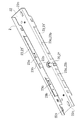
- FIG. 1 is a perspective configuration diagram showing a use state of an assist mechanism according to an embodiment of the present invention as viewed obliquely from below.
- FIG. 2 is a perspective configuration diagram illustrating the usage state of the assist mechanism according to the embodiment as viewed obliquely from above.
- FIG. 3 is a bottom view showing a unit including a receiving member constituting the assist mechanism according to the embodiment.
- FIG. 4 is a bottom view of the unit of FIG. 3 with the cover body constituting the unit removed.
- FIG. 5 is a perspective view showing the unit of FIG. 3 with the cover body constituting the unit removed.
- FIG. 6 is a bottom view of the receiving member in the first position.
- FIG. 1 is a perspective configuration diagram showing a use state of an assist mechanism according to an embodiment of the present invention as viewed obliquely from below.
- FIG. 2 is a perspective configuration diagram illustrating the usage state of the assist mechanism according to the embodiment as viewed obliquely from above.
- FIG. 3 is
- FIG. 7 is a bottom configuration diagram showing a state in which the receiving member is in a position slightly rotated from the first position toward the second position to capture the received member.
- FIG. 8 is a bottom configuration diagram in a state where the receiving member is in the second position and the door is in the closed position. A part of the description of the door is omitted, and the outline of the received member is indicated by a two-dot chain line.
- FIG. 9 is an exploded perspective view of the receiving member.
- FIG. 10 is a perspective view of the upper part constituting the receiving member.
- FIG. 11 is a perspective view of a slider included in the unit of FIG. 12 is a perspective view of an additional slider included in the unit of FIG.
- FIG. 13 is a perspective view of a base body constituting the unit of FIG. FIG.
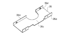
- FIG. 14 is a perspective view of a cover body constituting the unit of FIG.
- FIG. 15 is a perspective view of the cover body constituting the unit of FIG. 3, and shows the cover body from a different direction from FIG.
- FIG. 16 is a bottom view of a door frame provided with a carving for storing and mounting the unit of FIG. 3 and a door supported by the door frame.
- FIG. 17 is a bottom view showing a state in which the unit of FIG. 3 is housed in the engraving of FIG.
- FIG. 18 is a bottom view showing a state in which the engraving is closed with a decorative cover from the state of FIG.
- FIG. 19 is a perspective view of the decorative cover of FIG.
- the assist mechanism operates when the door is moved forward to a predetermined position toward the closed position, and functions to assist, that is, assist the forward movement of the door to the closed position. Is.
- the assist mechanism includes a receiving member 1 and a receiving member 7.
- the receiving member 1 assists the forward movement of the door D by capturing the received member 7 at a predetermined position when the door D is moved forward toward the closed position.
- the receiving member 7 is provided on the door D, and the receiving member 1 is provided on the door frame F that supports the receiving member 7 via the hinge Da.
- the receiving member 7 On the hinge Da side of the door D, the receiving member 7 has an engraving Dc opened upward on the upper end surface Db of the door D, and the upper surface of the receiving member 7 is substantially flush with the upper end surface Db of the door D. It is paid in this way.
- the received member 7 has a hook shape that allows a part of the receiving member 1 to enter the inside of the hook at a predetermined position when the door D is moved forward toward the reference position (closed position in the illustrated example).
- Part 70 In the illustrated example, such a hook-like portion 70 is formed by engraving a groove-like recess 72 on the upper surface portion of the disk-like body 71 that is received and fixed in the engraving Dc.
- the recess 72 has a groove rear end 73a positioned on the hinge Da side of the door D and extends in the left-right direction of the door D.
- the recess 72 communicates with the linear groove 73 and rotates the door D toward the closed position. It has an introduction groove 74 that is opened outward on the one surface Dd side of the door D that is positioned forward when it is moved.
- a hook-like portion 70 having a hook end directed toward the free end De of the door D is formed at a communication location between the linear groove portion 73 and the introduction groove portion 74.
- the introduction groove portion 74 is formed by inclining a groove wall 74a continuous with the groove wall 73b on the side facing the hook-shaped portion 70 in the linear groove portion 73 so as to approach the free end De of the door D toward the introduction opening.
- the guide surface 74b is used.
- a notch Df that communicates with the introduction opening of the introduction groove 74 is formed on the one surface Dd side of the door D.
- a catching portion 10 to be described later of the receiving member 1 has its axis lined up and down, and its lower end 10a is below the upper end surface Db of the door D and above the introduction groove portion 74 of the receiving member 7 and the groove bottom of the linear groove portion 73.
- the receiving member 1 has been rotated to the second position on the outside of the hook end of the hook-like portion 70 of the receiving member 7 without capturing the receiving member 7.
- a recess 75 in which the capturing part 10 is accommodated is formed at the reference position when the door D is moved forward from the (malfunction state).
- the hook end of the hook-like portion 70 is configured to be located inward from the outer edge 71a of the disk-like body 71 constituting the member 7 to be received.
- the recess 75 is formed between the ends.
- the receiving member 1 is rotated in the horizontal direction around the vertical axis 20 in the engraving Fc with the lower open surface formed in front of the door contact portion Fb on the hinge Da side of the door D in the upper portion Fb of the door frame F. It is prepared to be movable.
- the engraving Fc is a rectangular depression that is long in the left-right direction.
- the receiving member 1 is pivotally supported by a metal shaft body 21 as the vertical shaft 20 in which a shaft base portion is fixed to a metal base body 2.
- the base body 2 has a substantially rectangular bottom plate portion 22 having a length slightly smaller than the length of the engraving Fc (the dimension of the door frame F in the left-right direction x) and a width substantially equal to the width of the engraving Fc. And a pair of front and rear side plate portions 23, 23 so as to form a channel with an open bottom surface. (FIG. 13)
- the base body 2 is screwed to the top surface Fd of the engraving Fc.
- the threaded portion 22a of the screw J for screwing is provided at the left and right ends of the bottom plate portion 22 of the base body 2 at two front and rear positions, respectively.
- the through portions 22a of the screws J are each formed in a long hole shape that is long in the left-right direction x of the door frame F.
- the shaft body 21 has a head (not shown) at its upper end.
- the bottom plate portion 22 of the base body 2 has a through-hole 22b having a size that does not allow the head of the shaft body 21 to pass through at a position in the middle in the left-right direction.
- the shaft body 21 is inserted into the through-hole 22b until the head of the shaft body 21 is hooked on the outer surface of the base body 2, and then the head side of the shaft body 21 is caulked to the base. It is made to adhere to the body 2.
- the receiving member 1 is disposed in the center of the base body 2, and a slider 3 is disposed between the receiving member 1 and an end portion 24 of the door D positioned on the hinge Da side of the base body 2.
- An additional slider 5 is disposed between the base body 2 and the end 25 positioned on the free end De of the door D.
- a metal cover body is provided between the front and rear side plate portions 23 ′ and 23 ′′ of the base body 2 so that the receiving member 1 is accommodated between the base body 2 and the bottom plate portion 22 of the base body 2.
- the cover body 26 has a channel shape with an open top surface provided with rising portions 26a on the front and rear sides, and the side plate portion 23 of the base body 2.
- the base body 2 is fixed in the left-right direction by screwing the rising portion 26a of the cover body 26 to the corresponding side plate 23 of the base body 2 so that the lower end of the cover body 26 and the lower surface 26b of the cover body 26 are the same surface. Is covered with the cover body 26.
- the base body 2 combined with the cover body 26 is stored in the engraving Dc so that the lower surface 26b of the cover body 26 does not protrude from the lower surface of the upper portion Fb of the door frame F.
- the capturing part 10 of the receiving member 1 has its lower end 10 a positioned below the lower surface 26 b of the cover body 26.
- the unit configured by receiving the receiving member 1 and the like in the base body 2 moves the slider 3 and the additional slider 5 in the length direction thereof, and the urging means 4 in the direction along the length direction. Since the layout is such that the central axis of the compression coil spring 4 ′ and the central axis of the piston damper 60 serving as the braking means 6 are arranged, it can be installed on the upper part Fb of the door frame F without any trouble.
- the receiving member 1 is provided so as to be able to turn at a constant angle between the first position and the second position, and is spaced apart from each other in the direction around the turning center, so that the capturing portion of the received member 7 10, the control pin 11, and the linkage pin 12, and the captured member 7 is captured by the capturing unit 10 or the captured received member 7 is released at the first position.
- the assist is performed by turning the second position to the second position.
- the receiving member 1 rotates in the horizontal direction about the vertical shaft 20 fixed to the bottom plate portion 22 of the base body 2.
- the capturing unit 10, the control pin 11, and the linking pin 12 are all in the shape of an axis, and the axis is along the vertical direction.
- the distance from the vertical axis 20 is the largest in the capturing unit 10, and the distance between the control pin 11 and the vertical axis 20 is substantially equal to the distance between the linkage pin 12 and the vertical axis 20.
- the capturing part 10 is located in front of the front side plate part 23 'facing the one surface Dd of the door D in the base body 2 in the first position (FIGS. 1 and 6), and the base body 2 in the second position. It is located below. (Fig. 8)
- the control pin 11 and the linking pin 12 are both provided so as to protrude toward the bottom plate portion 22 side of the base body 2 and are always positioned in the base body 2.
- the control pin 11 is positioned on the hinge Da side of the door D, and the linkage pin 12 is always positioned on the free end side De of the door D.
- the receiving member 1 is configured by combining a lower part indicated by reference numeral 13 and an upper part indicated by reference numeral 14 in FIG.
- the lower part 13 has a fan-shaped part 13a and an arm part 13b protruding in a horizontal direction from the essential position of the fan-shaped part 13a, and the capturing part 10 is formed at the tip of the arm part 13b.
- the upper part 14 has a fan-like shape in which the fan-shaped part 13a of the lower part 13 is attached to the lower surface, and has a boss part 14a at the essential position, and a shaft through which the vertical shaft 20 passes from above in the boss part 14a.
- a hole 14b is provided, and the control pin 11 and the linkage pin 12 are provided in a protruding shape on the upper surface.
- the base part of the arm part 13b of the lower part 13 is formed with a screw through hole 13c screwed to the lower end side of the vertical shaft 20 passed through the shaft hole 14b, and the fan-like part 13a and the arm part 13b.
- a step 13d corresponding to the protruding dimension of the boss portion 14a is formed between the two.
- the slider 3 is provided in the base body 2 so as to be slidable in the direction of approaching and separating from the receiving member 1.
- a guide groove 30 for the control pin 11 is formed in the slider 3.
- the slider 3 is urged by the urging means 4 in a direction approaching the receiving member 1.
- the slider 3 has a gap between a front side plate portion 23 ′ formed on the side of the base body 2 facing the one surface Dd of the door D and a rear side plate portion 23 ′′ opposite thereto. It has a board-shaped main body 31 with a small width, and is slid and moved in the length direction of the base body 2, that is, the left-right direction x of the door frame F, guided by the side plate portions 23 ′, 23 ′′. It is like that.
- An ear 32 having a thickness that fits between the upper surface of the upper part 14 of the receiving member 1 and the bottom plate 22 of the base body 2 is formed on the side of the main body 31 that faces the center of the base body 2. Has been.
- the guide groove 30 is formed so as to penetrate the ear portion 32 up and down, and the control pin 11 is inserted into the guide groove 30 from below so that the receiving member 1 and the slider 3 are combined. Further, one end of a rod 33 protruding along the length direction of the base body 2 is formed on a side portion of the main body 31 facing the end portion 24 side of the base body 2 on the hinge Da side of the door D. Connected together. An end part indicated by reference numeral 27 in the drawing is fixed to the end 24 side of the base body 2 that is positioned on the hinge Da side of the door D, and the rod 33 is inserted into the through hole 27a formed in the end part 27. Is to be inserted.
- a compression coil spring 4 ′ is wound around the rod 33 between the main body 31 and the end part 27, and the slider 3 is urged in a direction approaching the receiving member 1 by the compression coil spring 4 ′. It has become. That is, in the illustrated example, the compression coil spring 4 ′ functions as the urging means 4.
- the guide groove 30 formed in the slider 3 as described above is formed so as to have a corner portion 30a with the biased tip side of the bias being bent or curved outward.
- the control pin 11 is on one side of the guide groove 30 with the corner portion 30a interposed therebetween, in the illustrated example, on the front end 30b side of the guide groove 30, and The rotation toward the second position is made against the bias.
- the guide groove 30 is not formed along a virtual circular arc centered on the vertical axis 20.
- the front end 30b of the guide groove 30 is positioned on the end 24 side of the base body 2 located on the hinge Da side of the door D relative to the rear end 30c, that is, on the biasing rear side of the biasing.
- the corner portion 30a is formed at a position approximately in the middle of the guide groove 30 in the front-rear direction.
- the slider 3 is urged in a direction close to the receiving member 1, but when the receiving member 1 is in the first position, the control pin 11 is positioned on the front end 30 b side of the guide groove 30.
- the rotation toward the second position resists the biasing, and thus the state where the receiving member 1 is in the first position is stably maintained.
- the receiving member 1 captures the received member 7 by the forward movement toward the closed position of the door D and is rotated toward the second position, the slider is moved until the control pin 11 gets over the corner portion 30a of the guide groove 30. 3 is moved in a direction against the bias.
- the rear end 30 c side of the guide groove 30 is urged by the urging means 4 via the slider 3 between the predetermined rotation position of the receiving member 1 and the second position.
- a groove portion 30d for changing the rotation speed of the receiving member 1 is provided.
- the rear end 30c side of the guide groove 30 is positioned slightly closer to the urging destination side than the corner portion 30a. Therefore, when the control pin 11 reaches the rear end 30c side of the guide groove 30, the slider 3 is slightly pushed again by the control pin 11 in the direction against the urging, and the receiving member 1 is rotated toward the second position. The subsidy by the energization of the is reduced. Thereby, in this embodiment, immediately before the door D reaches the reference position, the assist with respect to the door D is weakened. For example, the door D as the door D does not close with a loud sound. It is like that.
- the additional slider 5 is provided in the base body 2 so as to be slidable in the direction of approaching and separating from the receiving member 1. At the same time, a linkage groove 50 for the linkage pin 12 is formed in the additional slider 5. The additional slider 5 is moved away from the receiving member 1 by the rotation of the receiving member 1 toward the second position by the connecting pin 12 and the connecting groove 50, and the movement is resisted by the braking means 6. Is to be granted.
- the additional slider 5 has a main body 51 having a disk shape with a width that fits in a small space between the front side plate portion 23 ′ and the rear side plate portion 23 ′′ in the base body 2.
- the door frame F is guided by the side plate portions 23 ′ and 23 ′′ to slide in the left-right direction x.
- An ear portion 52 having a thickness that fits between the upper surface of the upper part 14 of the receiving member 1 and the bottom plate portion 22 of the base body 2 is formed on a side portion of the main body 51 that faces the center side of the base body 2.
- the linkage groove 50 is formed so as to penetrate the ear portion 52 vertically, and the linkage pin 12 is inserted into the linkage groove 50 from below so that the receiving member 1 and the additional slider 5 are combined.
- the main body 51 is combined with a so-called piston damper 60 including a cylinder 61, a piston (not shown), and a piston rod 62 connected to the piston.
- the piston damper 60 moves the piston in the left-right direction x of the door frame F and applies a resistance force to the movement of the piston toward the inner side of the cylinder 61.
- a holding space for receiving and holding the cylinder 61 of the piston damper 60 is formed in the main body 51 of the additional slider 5. This holding space is opened at the side of the main body 51 facing the end 25 that is located on the free end De of the door D in the base body 2, and from there the piston rod toward the end 21. 62 is protruded.
- An end part indicated by reference numeral 28 is fixed to the end 25 side of the base body 2 that is located on the free end De of the door D, and the protruding end of the piston rod 62 is fixed to the end part 28. It has become so.
- the piston damper 60 functions as the braking means 6.
- the linkage groove 50 formed in the additional slider 5 as described above is not formed along a virtual circular arc centered on the vertical axis 20.
- the linkage groove 50 is bent so that the slider 3 side is bent outward.
- the linking pin 12 When the receiving member 1 is in the first position, the linking pin 12 is positioned at the rear end 50b of the linking groove 50. (FIGS. 4 and 6) When the receiving member 1 is rotated toward the second position, the additional slider 5 is moved away from the receiving member 1 by being pushed by the linkage pin 12. As a result, the receiving member 1 is rotated toward the second position, that is, the braking force of the braking means 6 acting on the forward movement of the door D assisted in the forward movement is applied to the receiving member 1. Yes.
- the linkage groove 50 changes or cancels the application of resistance to the rotation of the receiving member 1 by the braking means 6 via the additional slider 5 between the predetermined rotating position and the second position of the receiving member 1.
- a groove portion 50c can also be provided.
- the distance between the bent portion 50d of the linkage groove 50 and the front end 50a approaches the end 25 positioned on the free end De of the door D in the base body 2 as the front end 50a is approached.
- the base body 2 extends in a direction crossing the length direction. If the connecting pin 12 enters between the bent portion 50d of the connecting groove 50 and the front end 50a immediately before the receiving member 1 reaches the second position, the additional slider 5 is moved away from the receiving member 1 at this time. The amount of movement can be reduced.
- the braking force on the door D is reduced to zero or reduced, and for example, a latch bolt constituting a door latch (not shown) provided in the door D is attached to the door frame. It can be made to move forward at a speed required for engaging with a receiving portion of the latch bolt provided on the F side.
- the receiving member 7 When the door D in the closed position is moved back in the opening direction, the receiving member 7 is captured and the receiving member 1 in the second position is rotated toward the first position, and is moved by this rotation.
- the control pin 11 After the slider 3 is once moved in a direction away from the receiving member 1 by the control pin 11, the control pin 11 approaches the receiving member 1 by the urging at a position where the control pin 11 enters the front end 30b side of the corner portion 30a of the guide groove 30.
- the state in which the receiving member 1 is in the first position is maintained again. Further, the additional slider 5 is moved in the direction close to the receiving member 1 by the linkage pin 12 moved by the rotation of the receiving member 1, and the piston rod 62 is pulled out from the cylinder 61 to the position before being pushed.
- the receiving member 1 and the slider 3 can be appropriately combined by simply placing the control pin 11 in the guide groove 30, and can be easily assembled, and the number of parts can be minimized. Can be a thing. Moreover, the rotation speed in each position of the receiving member 1 can be easily changed as needed by changing the shape of the guide groove 30.
- the receiving member 1 is pivotally supported by the vertical shaft 20 made of the metal shaft body 21 having the shaft base portion fixed to the metal base body 2.
- the rigidity of the portion of the base body 2 where the kinetic energy is directly applied via the receiving member 1 is effectively increased.
- the door as the movable body is relatively heavy at 40 to 50 kg. Therefore, even if the kinetic energy when the door D moves forward to the reference position is relatively large, the kinetic energy in the base body 2 is directly No deformation or the like occurs in the part that is acted on automatically.
- the slider 3 and the additional slider 5 are sandwiched between the pair of side plate portions 23, 23 of the base body 2 having a channel shape. Since the parts 23 and 23 are slid and guided, the rigidity of the portion of the base body 2 where the kinetic energy is indirectly applied via the slider 3 and the additional slider 5 is also effective. Has been enhanced.
- the support member 1 is installed between the pair of side plate portions 23 and 23 of the base body 2 so as to store the receiving member 1 between the base plate 2 and the bottom plate portion 22. Since the metal cover body 26 is provided, the portion that receives the kinetic energy in the base body 2 has a rectangular tube shape, and its rigidity is further enhanced.
- the sliding contact portion 26c of the receiving member 1 is formed on the upper surface 26d of the cover body 26 thus provided.
- the lower surface of the fan-shaped portion 13 a of the lower part of the receiving member 1 is in sliding contact with the upper surface 26 d of the cover body 26.
- the door D is supported at two places, that is, the shaft body 21 as the vertical shaft 20 and the sliding contact portion 26c of the cover body 26, so that the rotation is made smooth. It is.
- the side plate 23 of the base body 2 is provided with a slit 23a along the moving direction of the slider 3 and the additional slider 5, that is, the left-right direction x of the door frame F.
- a rail portion 23b with respect to the slider 3 is formed by projecting inward from the base body 2 between 23a and the tip of the side plate portion 23, that is, the lower end.
- a slit 23 a is formed at a position between the base and the lower end of the side plate portion 23 of the base body 2, and a portion located between the slit 23 a and the lower end of the side plate portion 23 is located. It protrudes inside the base body 2 by plastic deformation.
- a rail portion 23 b as a step toward the bottom plate portion 22 is formed inside the side plate portion 23.
- Each of the slider 3 and the additional slider 5 has step surfaces 31a and 51a facing downward respectively before and after the slider 3, and the additional slider 5 slides the step surfaces 31a and 51a on the rail portion 23b. It is accommodated in the base body 2 so as to contact. Thereby, in this embodiment, the slider 3 can be guided without backlash by the side plate portion 23 of the base body 2.
- the assist mechanism according to this embodiment further includes a decorative cover 8 that closes an opening portion of the engraving Fc formed on the upper portion of the door frame F.
- the decorative cover 8 has a substantially rectangular plate shape having a length substantially equal to the length of the engraving Fc and a width substantially equal to the width of the engraving Fc.
- a recess 80 is formed at a position in the middle of the length direction of the decorative cover 8 in which the base portion of the arm portion 13b of the receiving member 1 is accommodated when the decorative cover 8 is attached to the base body 2.
- a convex portion 82 protruding upward from the upper surface is provided, and a part of the convex portion 82 is an elastic piece 82a.
- the elastic piece 82a is configured such that the upper end is a free end 82b and the lower end is a deformation center, and the engaging end 82c is provided on the free end 82b.
- the base body 2 is provided with engaging recesses 27b, 28a for the engaging claws 82c so as to have a length in the left-right direction x of the door frame F.
- the elastic pieces 82 a are provided at two front and rear positions on the left and right ends of the decorative cover 8, respectively.
- the end parts 27 and 28 are respectively formed with engaging recesses 27b and 28a corresponding thereto.
- the length of the engaging claw 82c in the left-right direction x is smaller than the length of the engaging recesses 27b, 28a in the left-right direction x.
- the engaging recess 28 a is formed on the inner side wall constituting the internal space of the end part 28.
- the engagement recess 27 b is formed on the outer wall of the end part 27.
- the size of the base body 2 in the left-right direction x of the door frame F is smaller than the size of the engraving Fc, and the threaded portion 22a of the screw J has a long hole shape in the left-right direction x of the door frame F. Therefore, the base body 2 can be temporarily fixed to the top surface Fd of the engraving Fc with the screw J while being movable in the left-right direction x.
- FIG. 17 In a state where the base body 2 is temporarily fixed to the door frame F, the door D is moved forward toward the closed position, and the base body 2 is moved to a position where the receiving member 7 receives the receiving portion 1 and the capturing portion 10 captures it. Is adjusted in the left-right direction x.
- the capturing portion 10 of the receiving member 1 hits the guide surface 74b of the introduction groove portion 74 of the receiving member 7 by the forward operation, and appropriately enters the linear groove portion 73 by the guidance of the guide surface 74b.
- the base body 2 is adjusted and moved as a whole within the range of the length of the through portion 22a.
- the base member 2 is finally fixed to the door frame F with screws J, so that the receiving member 1 can be appropriately fixed to the door frame F.
- the decorative cover 8 closes the opening portion of the engraved Fc in combination with the base body 2 by the hooking claw 82c and the hooking recesses 27b and 28a.
- the base body 2 is adjusted and moved by the length of the hooking recesses 27b and 28a.
Abstract
The present invention is provided with a base body that pivotally supports a reception member and that is screwed into an engraved top surface formed above a door frame, and an ornamental cover that blocks an opening part of the engraved section. The dimensions of the base body in the left-right direction of the door frame are smaller than the dimensions of the engraved section. A screw passing section has a long oblong hole shape in the left-right direction of the door frame, and the base body is provided with a latch depression for a latch claw disposed on the ornamental cover so as to be long in the left-right direction of the door frame.
Description
この発明は、扉が閉じ位置に向けて所定位置まで往動操作されたときに作動して、この扉の閉じ位置への往動をアシスト、つまり補助する機構に関する。
The present invention relates to a mechanism that operates when the door is moved forward to a predetermined position toward the closed position, and assists, that is, assists the forward movement of the door to the closed position.
扉の閉止をアシストする機構として、閉じ込み操作により所定位置に扉が至ったときに扉側に設けられたストライカを捕捉してそこから付勢手段の付勢により強制的に回動するキャッチャーを有し、このキャッチャーによって扉を閉じ位置まで引き込むようにしたものがある。(特許文献1参照)かかるキャッチャーの強制的な回動は、このキャッチャーに近接する向きに付勢されたスライダの当接部をキャッチャーの被当接部に押し当てることによりなされている。
As a mechanism that assists in closing the door, a catcher that catches the striker provided on the door side when the door reaches a predetermined position by the closing operation and forcibly rotates by the biasing means from there. There is one that has the door pulled into the closed position by this catcher. (See Patent Document 1) The catcher is forcibly rotated by pressing a contact portion of a slider biased in a direction approaching the catcher against a contacted portion of the catcher.
この発明が解決しようとする主たる問題点は、この種のアシスト機構における戸枠側に取り付けられる受け部材を、かかる戸枠の上部の外観性を損なうことなく、かかる戸枠に適切に取り付け可能とする点にある。
The main problem to be solved by the present invention is that the receiving member attached to the door frame side in this type of assist mechanism can be appropriately attached to the door frame without impairing the appearance of the upper part of the door frame. There is in point to do.
前記課題を達成するために、この発明にあっては、扉のアシスト機構を、扉の上端に備えられる被受け部材と、戸枠の上部に備えられて扉を閉じ位置に向けて往動操作したときに所定位置においてこの被受け部材を捕捉して扉のこの往動をアシストする受け部材とを備えてなるアシスト機構であって、
受け部材は、第一位置と第二位置との間に亘る一定角度の回動可能に備えられ、かつ、前記第一位置において捕捉部による被受け部材の捕捉又は捕捉された被受け部材の解放をなし、この捕捉状態からの第二位置への回動により前記アシストをなすようになっていると共に、
この受け部材を軸支し、かつ、前記戸枠の上部に形成された彫り込みの天面にネジ止めされるベース体と、
前記彫り込みの開放部を塞ぐ化粧カバーとを備えており、
前記戸枠の左右方向における前記ベース体の寸法は前記彫り込みの寸法よりも小さく、かつ、このベース体における前記ネジの通し部はこの戸枠の左右方向に長い長孔状をなしていると共に、
前記ベース体には、前記化粧カバーに設けた掛合爪に対する掛合凹部が、前記戸枠の左右方向において長さを持つように備えられているものとした。 In order to achieve the above object, according to the present invention, the door assist mechanism is provided with a receiving member provided at the upper end of the door and an upper part of the door frame, and the door is moved forward toward the closed position. An assist mechanism comprising a receiving member that captures the received member at a predetermined position and assists the forward movement of the door,
The receiving member is provided so as to be rotatable at a constant angle between the first position and the second position, and the receiving member is captured by the capturing unit or released from the captured member in the first position. The assist is made by turning to the second position from this capture state,
A base body that pivotally supports the receiving member and is screwed to the top surface of the carved formed on the upper part of the door frame,
A decorative cover for closing the engraving opening,
The size of the base body in the left-right direction of the door frame is smaller than the size of the engraving, and the threading portion of the base body has a long hole shape in the left-right direction of the door frame,
The base body is provided with an engaging recess for an engaging claw provided on the decorative cover so as to have a length in the left-right direction of the door frame.
前記戸枠の左右方向における前記ベース体の寸法は前記彫り込みの寸法よりも小さく、かつ、前記ネジの通し部はこの戸枠の左右方向に長い長孔状をなしていることから、ベース体は彫り込みの天面に左右方向に可動可能な状態でネジにより仮止めすることができる。戸枠にベース体を仮止めした状態において扉を閉じ位置に向けて往動操作し、被受け部材を受け部材の捕捉部が捕捉する位置までベース体を前記左右方向に移動調整する。そしてこの後、ベース体をネジにより戸枠に本止めすることで、戸枠に受け部材を適切に固定させることができる。化粧カバーは彫り込みの開放部を、前記掛合爪と掛合凹部とによりベース体に組み合わされて塞ぐが、前記掛合凹部の長さによりベース体が前記調整移動されてもこの掛合凹部に掛合爪を掛合させることが可能とされる。
前記受け部材を、金属製のベース体に軸基部を固着させた金属製の軸体によって軸支させてなるものとすることが、好ましい態様の一つである。このようにした場合、ベース体における受け部材を介してこの運動エネルギーが直接的に作用される部分の剛性を効果的に高めることができる。
前記受け部材の側方に、連係手段によりこの受け部材の回動に連動して移動するスライダと、このスライダを介して前記受け部材の第二位置に向けた回動に付勢力を作用させる付勢手段とを備えさせると共に、
ベース体を、軸体の備えられた底板部と、前記スライダを間に挟んでこのスライダの前記移動をガイドする一対の側板部とを備えた、チャンネル状をなすように構成させておくこともある。
このようにした場合、ベース体における前記スライダを介して前記運動エネルギーが間接的に作用される部分の剛性も効果的に高めることができる。
この場合さらに、前記ベース体が、前記底板部との間に受け部材の一部を納めるようにこのベース体の一対の側板部間に架設される金属製のカバー体を備えるようにしておくこともある。このようにした場合、ベース体における前記運動エネルギーを受ける部分は角筒状とされ、その剛性を一層高めることができる。
また、前記カバー体の内面に受け部材の摺接部を形成させておくこともある。このようにした場合、扉を前記軸体とカバー体の摺接部の二カ所で支持してその回動はブレなくなされる。
前記ベース体の側板部にスライダの移動方向に沿ったスリットを設けると共に、このスリットとこの側板部の先端との間をベース体の内方に突出させてスライダに対するレール部とさせるようにしておけば、ベース体の側板部によってスライダをガタつきなく案内することができる。 Since the dimension of the base body in the left-right direction of the door frame is smaller than the engraved dimension, and the threading portion of the screw has a long hole shape in the left-right direction of the door frame, the base body is It can be temporarily fixed to the engraved top surface with screws in a state of being movable in the left-right direction. In a state where the base body is temporarily fixed to the door frame, the door is moved forward toward the closed position, and the base body is moved and adjusted in the left-right direction to a position where the receiving member receives the receiving portion. Then, the base member is finally fixed to the door frame with screws, whereby the receiving member can be appropriately fixed to the door frame. The decorative cover closes the engraved open part by combining the engaging claw and the engaging recess with the base body, but the engaging claw engages with the engaging recess even if the base body is adjusted and moved by the length of the engaging recess. It is possible to make it.
In one preferred embodiment, the receiving member is pivotally supported by a metal shaft having a shaft base fixed to a metal base. When it does in this way, the rigidity of the part to which this kinetic energy acts directly via the receiving member in a base body can be improved effectively.
A slider that moves in conjunction with the rotation of the receiving member by linkage means on the side of the receiving member, and an urging force is applied to the rotating toward the second position of the receiving member via the slider. As well as force means,
The base body may be configured to have a channel shape including a bottom plate portion provided with a shaft body and a pair of side plate portions that sandwich the slider and guide the movement of the slider. is there.
When it does in this way, the rigidity of the part to which the said kinetic energy acts indirectly via the said slider in a base body can also be raised effectively.
In this case, further, the base body is provided with a metal cover body constructed between a pair of side plate portions of the base body so as to accommodate a part of the receiving member between the base plate portion and the base plate portion. There is also. In this case, the portion of the base body that receives the kinetic energy is shaped like a square tube, and the rigidity can be further increased.
Further, a sliding contact portion of the receiving member may be formed on the inner surface of the cover body. In such a case, the door is supported at two positions of the sliding contact portion of the shaft body and the cover body, and the rotation is made without blurring.
A slit is provided in the side plate portion of the base body along the moving direction of the slider, and the space between the slit and the tip of the side plate portion protrudes inward of the base body to form a rail portion for the slider. For example, the slider can be guided without play by the side plate portion of the base body.
この発明によれば、この種のアシスト機構における戸枠側に取り付けられる受け部材を、かかる戸枠の上部の外観性を損なうことなく、かかる戸枠に適切に取り付けることができる。
According to this invention, the receiving member attached to the door frame side in this type of assist mechanism can be appropriately attached to the door frame without impairing the appearance of the upper part of the door frame.
以下、図1~図19に基づいて、この発明の典型的な実施の形態について、説明する。この実施の形態にかかるアシスト機構は、扉が閉じ位置に向けて所定位置まで往動操作されたときに作動して、この扉の閉じ位置への往動をアシスト、つまり補助するように機能するものである。
Hereinafter, typical embodiments of the present invention will be described with reference to FIGS. The assist mechanism according to this embodiment operates when the door is moved forward to a predetermined position toward the closed position, and functions to assist, that is, assist the forward movement of the door to the closed position. Is.
かかるアシスト機構は、受け部材1と被受け部材7とを備えてなる。そして、かかる受け部材1は扉Dを閉じ位置に向けて往動操作したときに所定位置においてこの被受け部材7を捕捉して扉Dのこの往動をアシストする。
The assist mechanism includes a receiving member 1 and a receiving member 7. The receiving member 1 assists the forward movement of the door D by capturing the received member 7 at a predetermined position when the door D is moved forward toward the closed position.
図示の例では、扉Dに被受け部材7を備えさせると共に、ヒンジDaを介してこれを支持する戸枠Fに受け部材1を備えさせた例を示している。
In the illustrated example, the receiving member 7 is provided on the door D, and the receiving member 1 is provided on the door frame F that supports the receiving member 7 via the hinge Da.
被受け部材7は、扉DのヒンジDa側において、扉Dの上端面Dbにおいて上方に開放された彫り込みDcに、被受け部材7の上面をこの扉Dの上端面Dbと略面一とするようにして納められている。図示の例では、被受け部材7は、扉Dを基準位置(図示の例では閉じ位置)に向けて往動操作したときに所定位置において受け部材1の一部をフック内側に入り込ませるフック状部70を有している。図示の例では、前記彫り込みDcに納められて固定される盤状体71の上面部に溝状の凹所72を刻設させることで、かかるフック状部70が形成されている。かかる凹所72は、扉DのヒンジDa側に溝奥端73aを位置させて扉Dの左右方向に延びる直線溝部73と、この直線溝部73に連通すると共に扉Dを閉じ位置に向けて回動させるときに前方に位置される扉Dの一面Dd側において外方に開放された導入溝部74とを有している。直線溝部73と導入溝部74の連通箇所にフック端を扉Dの自由端側Deに向けたフック状部70が形成されている。導入溝部74は直線溝部73における前記フック状部70に対向する側の溝壁73bに連続する溝壁74aをその導入開口に向かうに連れて扉Dの自由端側Deに近づく向きに傾斜させた案内面74bとしている。また、扉Dの前記一面Dd側には導入溝部74の前記導入開口に連通した切り欠きDfが形成されている。受け部材1の後述する捕捉部10は軸線を上下に沿わせると共に、その下端10aを扉Dの上端面Dbより下方で被受け部材7の導入溝部74及び直線溝部73の溝底よりも上方に位置させた軸状をなすように構成されており、扉Dを閉じ位置に向けて往動回動させると所定位置において後述の第一位置にある受け部材1の捕捉部10が被受け部材7の前記導入溝部74内に入り込む。入り込んだ捕捉部10は前記案内面74bに当接し、この案内面74bの傾斜により受け部材1は第二位置に向けた正転回動を開始し、この回動により捕捉部10は直線溝部73に入り込む。(図6から図7)これにより受け部材1による被受け部材7の捕捉がなされる。この捕捉状態からの後述のスライダ3を介した付勢手段4の付勢により受け部材1は垂直軸20を中心に水平方向に第二位置まで回動され、この回動により扉Dは閉じ位置まで引き込まれる。(図8)閉じ位置にある扉Dを開き位置に向けて復動操作すると、被受け部材7を捕捉している受け部材1は第一位置まで逆転回動され第一位置に至ると前記直線溝部73から捕捉部10を抜け出させる。これにより受け部材1から被受け部材7は解放される。
On the hinge Da side of the door D, the receiving member 7 has an engraving Dc opened upward on the upper end surface Db of the door D, and the upper surface of the receiving member 7 is substantially flush with the upper end surface Db of the door D. It is paid in this way. In the illustrated example, the received member 7 has a hook shape that allows a part of the receiving member 1 to enter the inside of the hook at a predetermined position when the door D is moved forward toward the reference position (closed position in the illustrated example). Part 70. In the illustrated example, such a hook-like portion 70 is formed by engraving a groove-like recess 72 on the upper surface portion of the disk-like body 71 that is received and fixed in the engraving Dc. The recess 72 has a groove rear end 73a positioned on the hinge Da side of the door D and extends in the left-right direction of the door D. The recess 72 communicates with the linear groove 73 and rotates the door D toward the closed position. It has an introduction groove 74 that is opened outward on the one surface Dd side of the door D that is positioned forward when it is moved. A hook-like portion 70 having a hook end directed toward the free end De of the door D is formed at a communication location between the linear groove portion 73 and the introduction groove portion 74. The introduction groove portion 74 is formed by inclining a groove wall 74a continuous with the groove wall 73b on the side facing the hook-shaped portion 70 in the linear groove portion 73 so as to approach the free end De of the door D toward the introduction opening. The guide surface 74b is used. Further, a notch Df that communicates with the introduction opening of the introduction groove 74 is formed on the one surface Dd side of the door D. A catching portion 10 to be described later of the receiving member 1 has its axis lined up and down, and its lower end 10a is below the upper end surface Db of the door D and above the introduction groove portion 74 of the receiving member 7 and the groove bottom of the linear groove portion 73. When the door D is moved forward and closed toward the closed position, the catching portion 10 of the receiving member 1 at the first position, which will be described later, is received at the predetermined position. Into the introduction groove 74. The trapping part 10 that has entered comes into contact with the guide surface 74b, and the receiving member 1 starts to rotate forwardly toward the second position due to the inclination of the guide surface 74b. Get in. (FIG. 6 to FIG. 7) Thereby, the receiving member 7 is captured by the receiving member 1. The receiving member 1 is rotated to the second position in the horizontal direction around the vertical shaft 20 by the urging force of the urging means 4 through the slider 3 described later from this captured state, and the door D is closed by this rotation. Drawn in. (FIG. 8) When the door D in the closed position is moved backward toward the open position, the receiving member 1 capturing the received member 7 is rotated reversely to the first position and reaches the first position. The capturing part 10 is pulled out from the groove part 73. As a result, the receiving member 7 is released from the receiving member 1.
この実施の形態にあっては、かかる被受け部材7のフック状部70のフック端の外側に、被受け部材7を捕捉せずに受け部材1が第二位置に回動してしまった状態(誤動作状態)から扉Dを往動操作したときに基準位置において前記捕捉部10の納まる凹所75が形成されている。図示の例では、フック状部70におけるフック端は、被受け部材7を構成する前記盤状体71の外縁71aより内方に位置されるように構成されており、これによりこの外縁71aとフック端との間に前記凹所75が形成されている。これにより、この実施の形態にあっては、前記誤動作状態のときに扉Dを基準位置としての閉じ位置まで往動回動させても受け部材1及び被受け部材7に破損が生じないようになっている。
In this embodiment, the receiving member 1 has been rotated to the second position on the outside of the hook end of the hook-like portion 70 of the receiving member 7 without capturing the receiving member 7. A recess 75 in which the capturing part 10 is accommodated is formed at the reference position when the door D is moved forward from the (malfunction state). In the illustrated example, the hook end of the hook-like portion 70 is configured to be located inward from the outer edge 71a of the disk-like body 71 constituting the member 7 to be received. The recess 75 is formed between the ends. As a result, in this embodiment, the receiving member 1 and the receiving member 7 are not damaged even if the door D is rotated forward to the closed position as the reference position in the malfunction state. It has become.
一方、受け部材1は、戸枠Fの上部Fbにおける扉DのヒンジDa側において、戸当たり部Fbの手前に形成された下面開放の彫り込みFc内に、垂直軸20を中心に水平方向に回動可能に備えられている。かかる彫り込みFcは、左右方向に長い長方形状の窪みとなっている。
On the other hand, the receiving member 1 is rotated in the horizontal direction around the vertical axis 20 in the engraving Fc with the lower open surface formed in front of the door contact portion Fb on the hinge Da side of the door D in the upper portion Fb of the door frame F. It is prepared to be movable. The engraving Fc is a rectangular depression that is long in the left-right direction.
この実施の形態にあっては、受け部材1は、金属製のベース体2に軸基部を固着させた、前記垂直軸20としての金属製の軸体21によって軸支されている。
In this embodiment, the receiving member 1 is pivotally supported by a metal shaft body 21 as the vertical shaft 20 in which a shaft base portion is fixed to a metal base body 2.
かかるベース体2は、前記彫り込みFcの長さ(戸枠Fの左右方向xの寸法)よりもやや小さい長さと、かかる彫り込みFcの幅と略等しい幅とを備えた、略長方形の底板部22と、前後一対の側板部23、23とを備えた、下面開放のチャンネル状をなすように構成されている。(図13)そして、かかるベース体2は前記彫り込みFcの天面Fdにネジ止めされるようになっている。かかるネジ止めのためのネジJの通し部22aが、ベース体2の底板部22の左右両端にそれぞれ、前後二カ所に設けられている。かかるネジJの通し部22aはそれぞれ戸枠Fの左右方向xに長い長孔状をなしている。
The base body 2 has a substantially rectangular bottom plate portion 22 having a length slightly smaller than the length of the engraving Fc (the dimension of the door frame F in the left-right direction x) and a width substantially equal to the width of the engraving Fc. And a pair of front and rear side plate portions 23, 23 so as to form a channel with an open bottom surface. (FIG. 13) The base body 2 is screwed to the top surface Fd of the engraving Fc. The threaded portion 22a of the screw J for screwing is provided at the left and right ends of the bottom plate portion 22 of the base body 2 at two front and rear positions, respectively. The through portions 22a of the screws J are each formed in a long hole shape that is long in the left-right direction x of the door frame F.
前記軸体21はその上端に図示しない頭部を有している。前記ベース体2の底板部22は、その左右方向中程の位置に、軸体21の頭部は通さない大きさの貫通孔22bを有している。図示の例では、この貫通孔22bに軸体21をベース体2の外面に軸体21の頭部が引っかかる位置まで軸体21を挿通した後、この軸体21の頭部側をカシメによりベース体2に固着させるようにしている。
The shaft body 21 has a head (not shown) at its upper end. The bottom plate portion 22 of the base body 2 has a through-hole 22b having a size that does not allow the head of the shaft body 21 to pass through at a position in the middle in the left-right direction. In the illustrated example, the shaft body 21 is inserted into the through-hole 22b until the head of the shaft body 21 is hooked on the outer surface of the base body 2, and then the head side of the shaft body 21 is caulked to the base. It is made to adhere to the body 2.
かかるベース体2内には、受け部材1の後述のアーム部13b以外の箇所、スライダ3とその付勢手段4、および、追加スライダ5とその制動手段6が納められている。受け部材1はベース体2の中央に配され、この受け部材1とベース体2における扉DのヒンジDa側に位置される端部24との間にスライダ3が配され、この受け部材1とベース体2における扉Dの自由端側Deに位置される端部25との間に追加スライダ5が配されている。
In the base body 2, a portion of the receiving member 1 other than the arm portion 13 b described later, the slider 3 and its biasing means 4, and the additional slider 5 and its braking means 6 are housed. The receiving member 1 is disposed in the center of the base body 2, and a slider 3 is disposed between the receiving member 1 and an end portion 24 of the door D positioned on the hinge Da side of the base body 2. An additional slider 5 is disposed between the base body 2 and the end 25 positioned on the free end De of the door D.
また、この実施の形態にあっては、ベース体2の底板部22との間に受け部材1を納めるようにこのベース体2の前後の側板部23’、23”間に金属製のカバー体26が架設されるようになっている。図示の例では、かかるカバー体26は、前後にそれぞれ立ち上がり部26aを備えた上面開放のチャンネル状を呈している。そして、ベース体2の側板部23の下端とカバー体26の下面26bとを同面とするように、カバー体26の立ち上がり26a部を対応するベース体2の側板部23にネジ止めすることで、ベース体2の左右方向中程の位置がかかるカバー体26によって覆われるようになっている。
Further, in this embodiment, a metal cover body is provided between the front and rear side plate portions 23 ′ and 23 ″ of the base body 2 so that the receiving member 1 is accommodated between the base body 2 and the bottom plate portion 22 of the base body 2. In the illustrated example, the cover body 26 has a channel shape with an open top surface provided with rising portions 26a on the front and rear sides, and the side plate portion 23 of the base body 2. The base body 2 is fixed in the left-right direction by screwing the rising portion 26a of the cover body 26 to the corresponding side plate 23 of the base body 2 so that the lower end of the cover body 26 and the lower surface 26b of the cover body 26 are the same surface. Is covered with the cover body 26.
このようにカバー体26と組み合わされたベース体2は、カバー体26の下面26bを戸枠Fの上部Fbの下面から突き出させないようにして、前記彫り込みDcに納められるようになっている。前記受け部材1の捕捉部10はその下端10aを前記カバー体26の下面26bより下方に位置させている。前記ベース体2内に受け部材1などを納めて構成されるユニットは、その長さ方向にスライダ3及び追加スライダ5を移動させ、また、この長さ方向に沿う向きに前記付勢手段4となる圧縮コイルバネ4’の中心軸及び前記制動手段6となるピストンダンパー60の中心軸を配させるレイアウトとなっていることから、戸枠Fの上部Fbに支障なく備え付けることが可能となっている。
Thus, the base body 2 combined with the cover body 26 is stored in the engraving Dc so that the lower surface 26b of the cover body 26 does not protrude from the lower surface of the upper portion Fb of the door frame F. The capturing part 10 of the receiving member 1 has its lower end 10 a positioned below the lower surface 26 b of the cover body 26. The unit configured by receiving the receiving member 1 and the like in the base body 2 moves the slider 3 and the additional slider 5 in the length direction thereof, and the urging means 4 in the direction along the length direction. Since the layout is such that the central axis of the compression coil spring 4 ′ and the central axis of the piston damper 60 serving as the braking means 6 are arranged, it can be installed on the upper part Fb of the door frame F without any trouble.
受け部材1は、第一位置と第二位置との間に亘る一定角度の回動可能に備えられると共に、この回動中心を巡る向きにおいてそれぞれ互いに距離を開けて、被受け部材7の捕捉部10と、制御ピン11と、連係ピン12とを有しており、前記第一位置において捕捉部10による被受け部材7の捕捉又は捕捉された被受け部材7の解放がなされ、この捕捉状態からの第二位置への回動により前記アシストをなすようになっている。
The receiving member 1 is provided so as to be able to turn at a constant angle between the first position and the second position, and is spaced apart from each other in the direction around the turning center, so that the capturing portion of the received member 7 10, the control pin 11, and the linkage pin 12, and the captured member 7 is captured by the capturing unit 10 or the captured received member 7 is released at the first position. The assist is performed by turning the second position to the second position.
かかる受け部材1は、ベース体2の底板部22に固定された前記垂直軸20を中心に水平方向に回動するようになっている。捕捉部10、制御ピン11及び連係ピン12はいずれも軸状をなし、その軸線を上下方向に沿わせている。垂直軸20からの距離は、捕捉部10が最も大きく、制御ピン11と垂直軸20との間の距離は連係ピン12と垂直軸20との間の距離と略等しくなっている。
The receiving member 1 rotates in the horizontal direction about the vertical shaft 20 fixed to the bottom plate portion 22 of the base body 2. The capturing unit 10, the control pin 11, and the linking pin 12 are all in the shape of an axis, and the axis is along the vertical direction. The distance from the vertical axis 20 is the largest in the capturing unit 10, and the distance between the control pin 11 and the vertical axis 20 is substantially equal to the distance between the linkage pin 12 and the vertical axis 20.
捕捉部10は、前記第一位置においてベース体2における前記扉Dの一面Ddに向き合う前側の側板部23’よりも前方に位置し、(図1、図6)前記第二位置においてベース体2の下方に位置するようになっている。(図8)
The capturing part 10 is located in front of the front side plate part 23 'facing the one surface Dd of the door D in the base body 2 in the first position (FIGS. 1 and 6), and the base body 2 in the second position. It is located below. (Fig. 8)
制御ピン11及び連係ピン12は、いずれもベース体2の底板部22側に突き出すように設けられていると共に、常時ベース体2内に位置されるようになっている。制御ピン11は扉DのヒンジDa側に位置され、これよりも連係ピン12は常に扉Dの自由端側Deに位置されるようになっている。
The control pin 11 and the linking pin 12 are both provided so as to protrude toward the bottom plate portion 22 side of the base body 2 and are always positioned in the base body 2. The control pin 11 is positioned on the hinge Da side of the door D, and the linkage pin 12 is always positioned on the free end side De of the door D.
図示の例では、受け部材1は、図10において符号13で示される下部パーツと、符号14で示される上部パーツとを組み合わせて構成されている。下部パーツ13は扇状部13aとこの扇状部13aの要位置から水平方向に突き出すアーム部13bとを有しており、アーム部13bの先端に捕捉部10が形成されている。上部パーツ14は下面に下部パーツ13の扇状部13aが添装される扇状を呈すると共に、その要位置にボス部14aを有し、このボス部14a内を上方から垂直軸20の通される軸穴14bとし、また、上面に前記制御ピン11及び連係ピン12を突き出し状に備えている。下部パーツ13のアーム部13bの基部には前記軸穴14bに通された垂直軸20の下端側にネジ止めされるネジの通し穴13cが形成されていると共に、その扇状部13aとアーム部13bとの間には前記ボス部14aの突きだし寸法分の段差13dが形成されている。
In the illustrated example, the receiving member 1 is configured by combining a lower part indicated by reference numeral 13 and an upper part indicated by reference numeral 14 in FIG. The lower part 13 has a fan-shaped part 13a and an arm part 13b protruding in a horizontal direction from the essential position of the fan-shaped part 13a, and the capturing part 10 is formed at the tip of the arm part 13b. The upper part 14 has a fan-like shape in which the fan-shaped part 13a of the lower part 13 is attached to the lower surface, and has a boss part 14a at the essential position, and a shaft through which the vertical shaft 20 passes from above in the boss part 14a. A hole 14b is provided, and the control pin 11 and the linkage pin 12 are provided in a protruding shape on the upper surface. The base part of the arm part 13b of the lower part 13 is formed with a screw through hole 13c screwed to the lower end side of the vertical shaft 20 passed through the shaft hole 14b, and the fan-like part 13a and the arm part 13b. A step 13d corresponding to the protruding dimension of the boss portion 14a is formed between the two.
スライダ3は、受け部材1に対し近接離隔する向きのスライド移動可能にベース体2内に備えられている。それと共に、かかるスライダ3には制御ピン11に対する案内溝30が形成されている。また、かかるスライダ3は、付勢手段4により、受け部材1に近接する向きに付勢されるようになっている。
The slider 3 is provided in the base body 2 so as to be slidable in the direction of approaching and separating from the receiving member 1. In addition, a guide groove 30 for the control pin 11 is formed in the slider 3. The slider 3 is urged by the urging means 4 in a direction approaching the receiving member 1.
図示の例では、スライダ3は、ベース体2における前記扉Dの一面Ddに向き合う側に形成された前側の側板部23’と、これに対向する後側の側板部23”との間に隙間少なく納まる幅を備えた盤状をなす主体部31を有し、両側板部23’、23”に案内されてベース体2の長さ方向、つまり、戸枠Fの左右方向xにスライド移動するようになっている。かかる主体部31におけるベース体2の中央側に向けられた側部には、受け部材1の上部パーツ14の上面とベース体2の底板部22との間に納まる厚さの耳部32が形成されている。前記案内溝30はこの耳部32を上下に貫通するように形成されており、制御ピン11を下方からこの案内溝30に入り込ませて受け部材1とスライダ3との組み合わせがなされている。また、かかる主体部31におけるベース体2における扉DのヒンジDa側に位置される端部24側に向けられた側部には、ベース体2の長さ方向に沿って突き出すロッド33の一端が一体に連接されている。ベース体2における扉DのヒンジDa側に位置される端部24側には図中符号27で示されるエンドパーツが固定されると共に、このエンドパーツ27に形成された貫通孔27aに前記ロッド33が挿通されるようになっている。かかるロッド33には主体部31とエンドパーツ27との間において圧縮コイルバネ4’が巻装されており、この圧縮コイルバネ4’によってスライダ3は受け部材1に近接する向きに付勢されるようになっている。すなわち、図示の例では、かかる圧縮コイルバネ4’が前記付勢手段4として機能するようになっている。
In the illustrated example, the slider 3 has a gap between a front side plate portion 23 ′ formed on the side of the base body 2 facing the one surface Dd of the door D and a rear side plate portion 23 ″ opposite thereto. It has a board-shaped main body 31 with a small width, and is slid and moved in the length direction of the base body 2, that is, the left-right direction x of the door frame F, guided by the side plate portions 23 ′, 23 ″. It is like that. An ear 32 having a thickness that fits between the upper surface of the upper part 14 of the receiving member 1 and the bottom plate 22 of the base body 2 is formed on the side of the main body 31 that faces the center of the base body 2. Has been. The guide groove 30 is formed so as to penetrate the ear portion 32 up and down, and the control pin 11 is inserted into the guide groove 30 from below so that the receiving member 1 and the slider 3 are combined. Further, one end of a rod 33 protruding along the length direction of the base body 2 is formed on a side portion of the main body 31 facing the end portion 24 side of the base body 2 on the hinge Da side of the door D. Connected together. An end part indicated by reference numeral 27 in the drawing is fixed to the end 24 side of the base body 2 that is positioned on the hinge Da side of the door D, and the rod 33 is inserted into the through hole 27a formed in the end part 27. Is to be inserted. A compression coil spring 4 ′ is wound around the rod 33 between the main body 31 and the end part 27, and the slider 3 is urged in a direction approaching the receiving member 1 by the compression coil spring 4 ′. It has become. That is, in the illustrated example, the compression coil spring 4 ′ functions as the urging means 4.
スライダ3に前記のように形成された案内溝30は、前記付勢の付勢先側を屈曲又は湾曲外側とするコーナー部30aを持つように形成されている。そして、受け部材1が第一位置にあるときに、制御ピン11は案内溝30のコーナー部30aを挟んだ一方側、図示の例では案内溝30の前端30b側にあって、受け部材1の第二位置に向けた回動が前記付勢に抗してなされるようになっている。
The guide groove 30 formed in the slider 3 as described above is formed so as to have a corner portion 30a with the biased tip side of the bias being bent or curved outward. When the receiving member 1 is in the first position, the control pin 11 is on one side of the guide groove 30 with the corner portion 30a interposed therebetween, in the illustrated example, on the front end 30b side of the guide groove 30, and The rotation toward the second position is made against the bias.
図示の例では、案内溝30は前記垂直軸20を中心とした仮想の円の円弧に沿うようには形成されていない。案内溝30の前端30bは後端30cよりもベース体2における扉DのヒンジDa側に位置される端部24側、つまり、前記付勢の付勢後方側に位置している。案内溝30の前後方向略中程の位置に前記コーナー部30aが形成されている。
In the illustrated example, the guide groove 30 is not formed along a virtual circular arc centered on the vertical axis 20. The front end 30b of the guide groove 30 is positioned on the end 24 side of the base body 2 located on the hinge Da side of the door D relative to the rear end 30c, that is, on the biasing rear side of the biasing. The corner portion 30a is formed at a position approximately in the middle of the guide groove 30 in the front-rear direction.
スライダ3は受け部材1に近接する向きに付勢されるが、受け部材1が第一位置にあるときは制御ピン11は案内溝30の前端30b側に位置されることから、受け部材1の第二位置に向けた回動は前記付勢に抗するものとなり、したがって、受け部材1が第一位置にある状態は安定的に維持される。扉Dの閉じ位置に向けた往動により受け部材1が被受け部材7を捕捉して第二位置に向けて回動されると制御ピン11が案内溝30のコーナー部30aを乗り越えるまではスライダ3は前記付勢に抗する向きに移動される。制御ピン11が案内溝30のコーナー部30aを乗り越えると制御ピン11はこのコーナー部30aよりも前記付勢の付勢後方側に入り込むことから、スライダ3は前記付勢の付勢先に移動され受け部材1の第二位置に向けた回動はこの付勢により助成される。これにより、受け部材1を通じて扉Dの閉じ位置への往動がアシストされる。
The slider 3 is urged in a direction close to the receiving member 1, but when the receiving member 1 is in the first position, the control pin 11 is positioned on the front end 30 b side of the guide groove 30. The rotation toward the second position resists the biasing, and thus the state where the receiving member 1 is in the first position is stably maintained. When the receiving member 1 captures the received member 7 by the forward movement toward the closed position of the door D and is rotated toward the second position, the slider is moved until the control pin 11 gets over the corner portion 30a of the guide groove 30. 3 is moved in a direction against the bias. When the control pin 11 gets over the corner portion 30a of the guide groove 30, the control pin 11 enters the biasing rear side of the corner portion 30a, so that the slider 3 is moved to the biasing destination. The rotation of the receiving member 1 toward the second position is assisted by this biasing. This assists the forward movement of the door D to the closed position through the receiving member 1.
この実施の形態にあっては、案内溝30の後端30c側は、受け部材1の所定の回動位置から第二位置までの間で、スライダ3を介した付勢手段4の付勢による受け部材1の回動の速度を変化させる溝部分30dを備えている。図示の例では、前記案内溝30の後端30c側はコーナー部30aよりもやや前記付勢先側に位置するようになっている。したがって、制御ピン11が案内溝30の後端30c側に至るとこの制御ピン11によってスライダ3は再び前記付勢に抗する向きにやや押し込まれ、受け部材1の第二位置に向けた回動の前記付勢による助成が減じるようになっている。これにより、この実施の形態にあっては、扉Dが基準位置に達する直前において、扉Dに対する前記アシストを弱めて、例えば、かかる扉Dとしての扉Dが大きな音を発して閉まることがないようになっている。
In this embodiment, the rear end 30 c side of the guide groove 30 is urged by the urging means 4 via the slider 3 between the predetermined rotation position of the receiving member 1 and the second position. A groove portion 30d for changing the rotation speed of the receiving member 1 is provided. In the illustrated example, the rear end 30c side of the guide groove 30 is positioned slightly closer to the urging destination side than the corner portion 30a. Therefore, when the control pin 11 reaches the rear end 30c side of the guide groove 30, the slider 3 is slightly pushed again by the control pin 11 in the direction against the urging, and the receiving member 1 is rotated toward the second position. The subsidy by the energization of the is reduced. Thereby, in this embodiment, immediately before the door D reaches the reference position, the assist with respect to the door D is weakened. For example, the door D as the door D does not close with a loud sound. It is like that.
追加スライダ5は、受け部材1に対し近接離隔する向きのスライド移動可能にベース体2内に備えられている。それと共に、かかる追加スライダ5には連係ピン12に対する連係溝50が形成されている。そして、この連係ピン12と連係溝50とにより、追加スライダ5は受け部材1の第二位置に向けた回動により受け部材1から離れる向きに移動されると共に、制動手段6によりこの移動に抵抗を付与されるようになっている。
The additional slider 5 is provided in the base body 2 so as to be slidable in the direction of approaching and separating from the receiving member 1. At the same time, a linkage groove 50 for the linkage pin 12 is formed in the additional slider 5. The additional slider 5 is moved away from the receiving member 1 by the rotation of the receiving member 1 toward the second position by the connecting pin 12 and the connecting groove 50, and the movement is resisted by the braking means 6. Is to be granted.
図示の例では、追加スライダ5は、ベース体2における前記前側の側板部23’と後側の側板部23”との間に隙間少なく納まる幅を備えた盤状をなす主体部51を有し、両側板部23’、23”に案内されて戸枠Fの左右方向xにスライド移動するようになっている。かかる主体部51におけるベース体2の中央側に向けられた側部には、受け部材1の上部パーツ14の上面とベース体2の底板部22との間に納まる厚さの耳部52が形成されている。前記連係溝50はこの耳部52を上下に貫通するように形成されており、連係ピン12を下方からこの連係溝50に入り込ませて受け部材1と追加スライダ5との組み合わせがなされている。
In the illustrated example, the additional slider 5 has a main body 51 having a disk shape with a width that fits in a small space between the front side plate portion 23 ′ and the rear side plate portion 23 ″ in the base body 2. The door frame F is guided by the side plate portions 23 ′ and 23 ″ to slide in the left-right direction x. An ear portion 52 having a thickness that fits between the upper surface of the upper part 14 of the receiving member 1 and the bottom plate portion 22 of the base body 2 is formed on a side portion of the main body 51 that faces the center side of the base body 2. Has been. The linkage groove 50 is formed so as to penetrate the ear portion 52 vertically, and the linkage pin 12 is inserted into the linkage groove 50 from below so that the receiving member 1 and the additional slider 5 are combined.
また、かかる主体部51には、シリンダ61と図示しないピストンとこのピストンに接続されたピストンロッド62とを備えてなるいわゆるピストンダンパー60が組み合わされている。かかるピストンダンパー60は、戸枠Fの左右方向xにピストンを移動させるようになっていると共に、シリンダ61の内奥に向けたピストンの移動に抵抗力を作用させるようになっている。図示の例では、かかるピストンダンパー60のシリンダ61を納め入れて保持する保持空間が追加スライダ5の主体部51に形成されている。この保持空間はベース体2における扉Dの自由端側Deに位置される端部25側に向けられた主体部51の側部において開放されており、そこからかかる端部21に向けてピストンロッド62が突き出されている。ベース体2における扉Dの自由端側Deに位置される端部25側には図中符号28で示されるエンドパーツが固定されると共に、このエンドパーツ28にピストンロッド62の突きだし端が固定されるようになっている。追加スライダ5が受け部材1から離れる向きに移動されるとピストンロッド62を介してピストンがシリンダ61内に押し込まれこの追加スライダ5の移動にピストンダンパー60の抵抗力が作用される。すなわち、図示の例では、かかるピストンダンパー60が前記制動手段6として機能するようになっている。
The main body 51 is combined with a so-called piston damper 60 including a cylinder 61, a piston (not shown), and a piston rod 62 connected to the piston. The piston damper 60 moves the piston in the left-right direction x of the door frame F and applies a resistance force to the movement of the piston toward the inner side of the cylinder 61. In the illustrated example, a holding space for receiving and holding the cylinder 61 of the piston damper 60 is formed in the main body 51 of the additional slider 5. This holding space is opened at the side of the main body 51 facing the end 25 that is located on the free end De of the door D in the base body 2, and from there the piston rod toward the end 21. 62 is protruded. An end part indicated by reference numeral 28 is fixed to the end 25 side of the base body 2 that is located on the free end De of the door D, and the protruding end of the piston rod 62 is fixed to the end part 28. It has become so. When the additional slider 5 is moved away from the receiving member 1, the piston is pushed into the cylinder 61 through the piston rod 62, and the resistance force of the piston damper 60 acts on the movement of the additional slider 5. That is, in the illustrated example, the piston damper 60 functions as the braking means 6.
追加スライダ5に前記のように形成された連係溝50も、前記垂直軸20を中心とした仮想の円の円弧に沿うようには形成されていない。また、連係溝50は前記スライダ3の側を屈曲外側とするように屈曲されている。
The linkage groove 50 formed in the additional slider 5 as described above is not formed along a virtual circular arc centered on the vertical axis 20. The linkage groove 50 is bent so that the slider 3 side is bent outward.
受け部材1が第一位置にあるとき、連係ピン12は連係溝50の後端50bに位置するようになっている。(図4、図6)受け部材1が第二位置に向けて回動されると連係ピン12に押されて追加スライダ5は受け部材1から離れる向きに移動される。これにより、受け部材1の第二位置に向けた回動、つまり、この受け部材1に往動をアシストされた扉Dのこの往動にかかる制動手段6の制動力を作用させるようになっている。
When the receiving member 1 is in the first position, the linking pin 12 is positioned at the rear end 50b of the linking groove 50. (FIGS. 4 and 6) When the receiving member 1 is rotated toward the second position, the additional slider 5 is moved away from the receiving member 1 by being pushed by the linkage pin 12. As a result, the receiving member 1 is rotated toward the second position, that is, the braking force of the braking means 6 acting on the forward movement of the door D assisted in the forward movement is applied to the receiving member 1. Yes.
前記連係溝50に、受け部材1の所定の回動位置から第二位置までの間で、追加スライダ5を介した制動手段6による受け部材1の回動への抵抗の付与を変化又は解除させる溝部分50cを備えさせることもできる。図示の例では、連係溝50の前記屈曲箇所50dと前端50aとの間はこの前端50aに近づくに連れてベース体2における扉Dの自由端側Deに位置される端部25に近づくようにベース体2の長さ方向に対して交叉する向きに延びている。受け部材1が第二位置に至る直前において連係ピン12がこの連係溝50の屈曲箇所50dと前端50aとの間に入り込むようにしておけば、このときに追加スライダ5を受け部材1から離れる向きに移動させないか、あるいは、その移動量を減じさせることができる。したがって、このようにすれば、扉Dが基準位置に達する直前において、扉Dに対する前記制動力を零あるいは減少させて、例えば、かかる扉Dに備えられる図示しないドアラッチを構成するラッチボルトを戸枠F側に備えられるこのラッチボルトの受け部に係合させるために必要な速度で往動されるようにするようにできる。
The linkage groove 50 changes or cancels the application of resistance to the rotation of the receiving member 1 by the braking means 6 via the additional slider 5 between the predetermined rotating position and the second position of the receiving member 1. A groove portion 50c can also be provided. In the illustrated example, the distance between the bent portion 50d of the linkage groove 50 and the front end 50a approaches the end 25 positioned on the free end De of the door D in the base body 2 as the front end 50a is approached. The base body 2 extends in a direction crossing the length direction. If the connecting pin 12 enters between the bent portion 50d of the connecting groove 50 and the front end 50a immediately before the receiving member 1 reaches the second position, the additional slider 5 is moved away from the receiving member 1 at this time. The amount of movement can be reduced. Accordingly, in this way, immediately before the door D reaches the reference position, the braking force on the door D is reduced to zero or reduced, and for example, a latch bolt constituting a door latch (not shown) provided in the door D is attached to the door frame. It can be made to move forward at a speed required for engaging with a receiving portion of the latch bolt provided on the F side.
閉じ位置にある扉Dをこれを開く向きに復動させると、被受け部材7を捕捉して第二位置にある受け部材1は第一位置に向けて回動され、この回動により移動される制御ピン11によりスライダ3は受け部材1から離れる向きに一旦移動された後にこの制御ピン11が案内溝30のコーナー部30aより前端30b側に入り込んだ位置で前記付勢により受け部材1に近接する向きに移動し、受け部材1が第一位置にある状態が再び維持される。また、かかる受け部材1の回動により移動される連係ピン12により追加スライダ5は受け部材1に近接する向きに移動されシリンダ61内からピストンロッド62は押し込み前の位置まで引き出される。
When the door D in the closed position is moved back in the opening direction, the receiving member 7 is captured and the receiving member 1 in the second position is rotated toward the first position, and is moved by this rotation. After the slider 3 is once moved in a direction away from the receiving member 1 by the control pin 11, the control pin 11 approaches the receiving member 1 by the urging at a position where the control pin 11 enters the front end 30b side of the corner portion 30a of the guide groove 30. The state in which the receiving member 1 is in the first position is maintained again. Further, the additional slider 5 is moved in the direction close to the receiving member 1 by the linkage pin 12 moved by the rotation of the receiving member 1, and the piston rod 62 is pulled out from the cylinder 61 to the position before being pushed.
この実施の形態にかかるアシスト機構は、前記受け部材1とスライダ3とは、前記制御ピン11を案内溝30に納めるだけで適切に組み合わせることができ、組立が容易であり、その部品点数も最小のものにすることができる。また、案内溝30の形状を変更することで、受け部材1の各位置での回動速度を必要に応じて容易に変更することができる。
In the assist mechanism according to this embodiment, the receiving member 1 and the slider 3 can be appropriately combined by simply placing the control pin 11 in the guide groove 30, and can be easily assembled, and the number of parts can be minimized. Can be a thing. Moreover, the rotation speed in each position of the receiving member 1 can be easily changed as needed by changing the shape of the guide groove 30.
また、この実施の形態にかかるアシスト機構にあっては、受け部材1は金属製のベース体2に軸基部を固着させた金属製の軸体21よりなる垂直軸20によって軸支されることから、ベース体2における受け部材1を介してこの運動エネルギーが直接的に作用される部分の剛性が効果的に高められている。これにより、可動体としての扉が40~50kgと比較的重く、したがって扉Dが基準位置に往動するときの運動エネルギーが比較的大きい場合であっても、ベース体2における前記運動エネルギーが直接的に作用される部分に変形などを生じさせることがない。
In the assist mechanism according to this embodiment, the receiving member 1 is pivotally supported by the vertical shaft 20 made of the metal shaft body 21 having the shaft base portion fixed to the metal base body 2. The rigidity of the portion of the base body 2 where the kinetic energy is directly applied via the receiving member 1 is effectively increased. As a result, the door as the movable body is relatively heavy at 40 to 50 kg. Therefore, even if the kinetic energy when the door D moves forward to the reference position is relatively large, the kinetic energy in the base body 2 is directly No deformation or the like occurs in the part that is acted on automatically.
また、この実施の形態にかかるアシスト機構にあっては、前記スライダ3及び追加スライダ5は、チャンネル状をなすベース体2の一対の側板部23、23間に挟まれた状態でこの一対の側板部23、23に案内されてスライド移動されるようになっていることから、ベース体2における前記スライダ3及び追加スライダ5を介して前記運動エネルギーが間接的に作用される部分の剛性も効果的に高められている。
In the assist mechanism according to this embodiment, the slider 3 and the additional slider 5 are sandwiched between the pair of side plate portions 23, 23 of the base body 2 having a channel shape. Since the parts 23 and 23 are slid and guided, the rigidity of the portion of the base body 2 where the kinetic energy is indirectly applied via the slider 3 and the additional slider 5 is also effective. Has been enhanced.
特に、この実施の形態にかかるアシスト機構にあっては、前記ベース体2の底板部22との間に受け部材1を納めるようにこのベース体2の一対の側板部23、23間に架設される金属製のカバー体26を備えていることから、ベース体2における前記運動エネルギーを受ける部分は角筒状とされ、その剛性が一層高められている。また、この実施の形態にあっては、このように備えられるカバー体26の上面26dに受け部材1の摺接部26cが形成されている。図示の例では、かかるカバー体26の上面26dに受け部材1の下部パーツの扇状部13aの下面が摺接するようになっている。これにより、この実施の形態にあっては、扉Dを前記垂直軸20としての軸体21とカバー体26の摺接部26cの二カ所で支持してその回動がブレなくなされるようにしてある。
In particular, in the assist mechanism according to this embodiment, the support member 1 is installed between the pair of side plate portions 23 and 23 of the base body 2 so as to store the receiving member 1 between the base plate 2 and the bottom plate portion 22. Since the metal cover body 26 is provided, the portion that receives the kinetic energy in the base body 2 has a rectangular tube shape, and its rigidity is further enhanced. In this embodiment, the sliding contact portion 26c of the receiving member 1 is formed on the upper surface 26d of the cover body 26 thus provided. In the illustrated example, the lower surface of the fan-shaped portion 13 a of the lower part of the receiving member 1 is in sliding contact with the upper surface 26 d of the cover body 26. Thereby, in this embodiment, the door D is supported at two places, that is, the shaft body 21 as the vertical shaft 20 and the sliding contact portion 26c of the cover body 26, so that the rotation is made smooth. It is.
また、この実施の形態にあっては、ベース体2の側板部23に前記スライダ3及び追加スライダ5の移動方向、つまり、戸枠Fの左右方向xに沿ったスリット23aを設けると共に、このスリット23aとこの側板部23の先端、つまり、下端との間をベース体2の内方に突出させてスライダ3に対するレール部23bとさせている。図示の例では、ベース体2の側板部23における基部と下端との中間となる位置にスリット23aが形成されていると共に、側板部23におけるこのスリット23aと下端との間に位置される箇所が塑性変形によりベース体2の内側に突出されている。そして、これにより、側板部23の内方に底板部22に向いた段差としてのレール部23bが形成されている。前記スライダ3及び追加スライダ5はいずれも、その前後にそれぞれ下方に向いた段差面31a、51aを有しており、かかるスライダ3及び追加スライダ5はこの段差面31a、51aをレール部23bに摺接させるようにしてベース体2内に納められている。これにより、この実施の形態にあっては、ベース体2の側板部23によってスライダ3をガタつきなく案内できるようになっている。
In this embodiment, the side plate 23 of the base body 2 is provided with a slit 23a along the moving direction of the slider 3 and the additional slider 5, that is, the left-right direction x of the door frame F. A rail portion 23b with respect to the slider 3 is formed by projecting inward from the base body 2 between 23a and the tip of the side plate portion 23, that is, the lower end. In the illustrated example, a slit 23 a is formed at a position between the base and the lower end of the side plate portion 23 of the base body 2, and a portion located between the slit 23 a and the lower end of the side plate portion 23 is located. It protrudes inside the base body 2 by plastic deformation. As a result, a rail portion 23 b as a step toward the bottom plate portion 22 is formed inside the side plate portion 23. Each of the slider 3 and the additional slider 5 has step surfaces 31a and 51a facing downward respectively before and after the slider 3, and the additional slider 5 slides the step surfaces 31a and 51a on the rail portion 23b. It is accommodated in the base body 2 so as to contact. Thereby, in this embodiment, the slider 3 can be guided without backlash by the side plate portion 23 of the base body 2.
また、この実施の形態にかかるアシスト機構はさらに、前記戸枠Fの上部に形成された前記彫り込みFcの開放部を塞ぐ化粧カバー8を備えている。かかる化粧カバー8は、前記彫り込みFcの長さと略等しい長さと、前記彫り込みFcの幅と略等しい幅とを備えた略長方形の板状をなしている。かかる化粧カバー8の長さ方向中程の位置には、ベース体2への取り付け時に受け部材1のアーム部13bの基部が納まる凹所80が形成されている。また、かかる化粧カバー8の上面側には、この上面から上方に突き出す凸部82が備えられていると共に、この凸部82の一部は弾性片82aとなっている。この弾性片82aは、上端を自由端82bとし、下端を変形中心とするように構成されていると共に、自由端82bに掛合爪82cを備えている。一方、前記ベース体2には、かかる掛合爪82cに対する掛合凹部27b、28aが、前記戸枠Fの左右方向xにおいて長さを持つように備えられている。図示の例では、弾性片82aは化粧カバー8の左右両端にそれぞれ、前後二カ所に設けられている。そして、前記エンドパーツ27、28にこれに対応した掛合凹部27b、28aがそれぞれ形成されている。前記左右方向xにおける掛合爪82cの長さ、すなわち、前記弾性片82aの幅は、この左右方向xにおける掛合凹部27b、28aの長さよりも小さくなっている。図示の例では、図5における右側では、掛合凹部28aはエンドパーツ28の内部空所を構成する内側壁に形成されている。図5における左側では、掛合凹部27bはエンドパーツ27の外側壁に形成されている。
Further, the assist mechanism according to this embodiment further includes a decorative cover 8 that closes an opening portion of the engraving Fc formed on the upper portion of the door frame F. The decorative cover 8 has a substantially rectangular plate shape having a length substantially equal to the length of the engraving Fc and a width substantially equal to the width of the engraving Fc. A recess 80 is formed at a position in the middle of the length direction of the decorative cover 8 in which the base portion of the arm portion 13b of the receiving member 1 is accommodated when the decorative cover 8 is attached to the base body 2. Further, on the upper surface side of the decorative cover 8, a convex portion 82 protruding upward from the upper surface is provided, and a part of the convex portion 82 is an elastic piece 82a. The elastic piece 82a is configured such that the upper end is a free end 82b and the lower end is a deformation center, and the engaging end 82c is provided on the free end 82b. On the other hand, the base body 2 is provided with engaging recesses 27b, 28a for the engaging claws 82c so as to have a length in the left-right direction x of the door frame F. In the illustrated example, the elastic pieces 82 a are provided at two front and rear positions on the left and right ends of the decorative cover 8, respectively. The end parts 27 and 28 are respectively formed with engaging recesses 27b and 28a corresponding thereto. The length of the engaging claw 82c in the left-right direction x, that is, the width of the elastic piece 82a is smaller than the length of the engaging recesses 27b, 28a in the left-right direction x. In the illustrated example, on the right side in FIG. 5, the engaging recess 28 a is formed on the inner side wall constituting the internal space of the end part 28. On the left side in FIG. 5, the engagement recess 27 b is formed on the outer wall of the end part 27.
前記戸枠Fの左右方向xにおける前記ベース体2の寸法は前記彫り込みFcの寸法よりも小さく、かつ、前記ネジJの通し部22aはこの戸枠Fの左右方向xに長い長孔状をなしていることから、ベース体2は彫り込みFcの天面Fdに左右方向xに可動可能な状態でネジJにより仮止めすることができる。(図17)戸枠Fにベース体2を仮止めした状態において扉Dを閉じ位置に向けて往動操作し、被受け部材7を受け部材1の捕捉部10が捕捉する位置までベース体2を前記左右方向xに移動調整する。具体的には、前記往動操作により受け部材1の捕捉部10が被受け部材7の導入溝部74の案内面74bに突き当たり、この案内面74bの案内により直線溝部73に適切に入り込むように、ベース体2を前記通し部22aの長さの範囲内において全体として調整移動する。そしてこの後、ベース体2をネジJにより戸枠Fに本止めすることで、戸枠Fに受け部材1を適切に固定させることができる。化粧カバー8は彫り込みFcの開放部を、前記掛合爪82cと掛合凹部27b、28aとによりベース体2に組み合わされて塞ぐが、前記掛合凹部27b、28aの長さによりベース体2が前記調整移動されてもこの掛合凹部27b、28aに掛合爪82cを掛合させることが可能とされる。(図18)
なお、2012年4月27日に出願された日本特許出願第2012-102648号及び同日に出願された日本特許出願第2012-102649号の明細書、特許請求の範囲、図面及び要約書の全内容をここに引用し、本発明の明細書の開示として、取り入れるものである。 The size of thebase body 2 in the left-right direction x of the door frame F is smaller than the size of the engraving Fc, and the threaded portion 22a of the screw J has a long hole shape in the left-right direction x of the door frame F. Therefore, the base body 2 can be temporarily fixed to the top surface Fd of the engraving Fc with the screw J while being movable in the left-right direction x. (FIG. 17) In a state where the base body 2 is temporarily fixed to the door frame F, the door D is moved forward toward the closed position, and the base body 2 is moved to a position where the receiving member 7 receives the receiving portion 1 and the capturing portion 10 captures it. Is adjusted in the left-right direction x. Specifically, the capturing portion 10 of the receiving member 1 hits the guide surface 74b of the introduction groove portion 74 of the receiving member 7 by the forward operation, and appropriately enters the linear groove portion 73 by the guidance of the guide surface 74b. The base body 2 is adjusted and moved as a whole within the range of the length of the through portion 22a. Then, the base member 2 is finally fixed to the door frame F with screws J, so that the receiving member 1 can be appropriately fixed to the door frame F. The decorative cover 8 closes the opening portion of the engraved Fc in combination with the base body 2 by the hooking claw 82c and the hooking recesses 27b and 28a. The base body 2 is adjusted and moved by the length of the hooking recesses 27b and 28a. Even if this is done, it is possible to engage the engaging claws 82c with the engaging recesses 27b and 28a. (Fig. 18)
The entire contents of the description, claims, drawings and abstract of Japanese Patent Application No. 2012-102648 filed on April 27, 2012 and Japanese Patent Application No. 2012-102649 filed on the same day Is hereby incorporated by reference as a disclosure of the specification of the present invention.
なお、2012年4月27日に出願された日本特許出願第2012-102648号及び同日に出願された日本特許出願第2012-102649号の明細書、特許請求の範囲、図面及び要約書の全内容をここに引用し、本発明の明細書の開示として、取り入れるものである。 The size of the
The entire contents of the description, claims, drawings and abstract of Japanese Patent Application No. 2012-102648 filed on April 27, 2012 and Japanese Patent Application No. 2012-102649 filed on the same day Is hereby incorporated by reference as a disclosure of the specification of the present invention.
Claims (1)
- 扉の上端に備えられる被受け部材と、戸枠の上部に備えられて扉を閉じ位置に向けて往動操作したときに所定位置においてこの被受け部材を捕捉して扉のこの往動をアシストする受け部材とを備えてなるアシスト機構であって、
受け部材は、第一位置と第二位置との間に亘る一定角度の回動可能に備えられ、かつ、前記第一位置において捕捉部による被受け部材の捕捉又は捕捉された被受け部材の解放をなし、この捕捉状態からの第二位置への回動により前記アシストをなすようになっていると共に、
この受け部材を軸支し、かつ、前記戸枠の上部に形成された彫り込みの天面にネジ止めされるベース体と、
前記彫り込みの開放部を塞ぐ化粧カバーとを備えており、
前記戸枠の左右方向における前記ベース体の寸法は前記彫り込みの寸法よりも小さく、かつ、このベース体における前記ネジの通し部はこの戸枠の左右方向に長い長孔状をなしていると共に、
前記ベース体には、前記化粧カバーに設けた掛合爪に対する掛合凹部が、前記戸枠の左右方向において長さを持つように備えられていることを特徴とする扉のアシスト機構。 A receiving member provided at the upper end of the door and an upper part of the door frame, when the door is moved forward toward the closed position, the received member is captured at a predetermined position to assist the forward movement of the door. An assist mechanism comprising a receiving member that performs
The receiving member is provided so as to be rotatable at a constant angle between the first position and the second position, and the receiving member is captured by the capturing unit or released from the captured member in the first position. The assist is made by turning to the second position from this capture state,
A base body that pivotally supports the receiving member and is screwed to the top surface of the carved formed on the upper part of the door frame,
A decorative cover for closing the engraving opening,
The size of the base body in the left-right direction of the door frame is smaller than the size of the engraving, and the threading portion of the base body has a long hole shape in the left-right direction of the door frame,
An assisting mechanism for a door, wherein the base body is provided with an engaging recess for an engaging claw provided on the decorative cover so as to have a length in the left-right direction of the door frame.
Priority Applications (1)
| Application Number | Priority Date | Filing Date | Title |
|---|---|---|---|
| CN201380021773.1A CN104246100B (en) | 2012-04-27 | 2013-04-26 | The auxiliary body of door |
Applications Claiming Priority (4)
| Application Number | Priority Date | Filing Date | Title |
|---|---|---|---|
| JP2012-102648 | 2012-04-27 | ||
| JP2012102649A JP2013231279A (en) | 2012-04-27 | 2012-04-27 | Door assisting mechanism |
| JP2012102648A JP2013231278A (en) | 2012-04-27 | 2012-04-27 | Assist mechanism for movable body |
| JP2012-102649 | 2012-04-27 |
Publications (1)
| Publication Number | Publication Date |
|---|---|
| WO2013162001A1 true WO2013162001A1 (en) | 2013-10-31 |
Family
ID=49483297
Family Applications (1)
| Application Number | Title | Priority Date | Filing Date |
|---|---|---|---|
| PCT/JP2013/062398 WO2013162001A1 (en) | 2012-04-27 | 2013-04-26 | Door assist mechanism |
Country Status (2)
| Country | Link |
|---|---|
| CN (1) | CN104246100B (en) |
| WO (1) | WO2013162001A1 (en) |
Cited By (1)
| Publication number | Priority date | Publication date | Assignee | Title |
|---|---|---|---|---|
| CN104806091A (en) * | 2014-01-27 | 2015-07-29 | 株式会社利富高 | Rotation assisting mechanism |
Families Citing this family (1)
| Publication number | Priority date | Publication date | Assignee | Title |
|---|---|---|---|---|
| CN107849889A (en) * | 2015-04-30 | 2018-03-27 | 亚萨合莱安全技术有限公司 | Gate driver with master driver and auxiliary actuator |
Citations (1)
| Publication number | Priority date | Publication date | Assignee | Title |
|---|---|---|---|---|
| WO2011142046A1 (en) * | 2010-05-14 | 2011-11-17 | スガツネ工業株式会社 | Door opening and closing device |
Family Cites Families (6)
| Publication number | Priority date | Publication date | Assignee | Title |
|---|---|---|---|---|
| JP4912318B2 (en) * | 2005-11-08 | 2012-04-11 | 株式会社ニフコ | Retraction mechanism |
| JP5248917B2 (en) * | 2008-05-28 | 2013-07-31 | 株式会社ムラコシ精工 | Door body closing device |
| JP2010048025A (en) * | 2008-08-22 | 2010-03-04 | Nishi Seisakusho:Kk | Closure assisting device |
| JP5377923B2 (en) * | 2008-10-20 | 2013-12-25 | 株式会社ニフコ | Movable body assist mechanism |
| JP5225199B2 (en) * | 2009-02-12 | 2013-07-03 | 株式会社ニフコ | Rotating body assist mechanism |
| JP5204711B2 (en) * | 2009-03-30 | 2013-06-05 | 株式会社久力製作所 | Door closer |
-
2013
- 2013-04-26 CN CN201380021773.1A patent/CN104246100B/en not_active Expired - Fee Related
- 2013-04-26 WO PCT/JP2013/062398 patent/WO2013162001A1/en active Application Filing
Patent Citations (1)
| Publication number | Priority date | Publication date | Assignee | Title |
|---|---|---|---|---|
| WO2011142046A1 (en) * | 2010-05-14 | 2011-11-17 | スガツネ工業株式会社 | Door opening and closing device |
Cited By (2)
| Publication number | Priority date | Publication date | Assignee | Title |
|---|---|---|---|---|
| CN104806091A (en) * | 2014-01-27 | 2015-07-29 | 株式会社利富高 | Rotation assisting mechanism |
| CN104806091B (en) * | 2014-01-27 | 2017-06-06 | 株式会社利富高 | Rotate auxiliary body |
Also Published As
| Publication number | Publication date |
|---|---|
| CN104246100A (en) | 2014-12-24 |
| CN104246100B (en) | 2016-06-29 |
Similar Documents
| Publication | Publication Date | Title |
|---|---|---|
| JP5377923B2 (en) | Movable body assist mechanism | |
| JP5368813B2 (en) | Forward movement mechanism of rotating body | |
| EP3059363B1 (en) | Locking device | |
| JP2016205128A (en) | Guide device for sliding door | |
| JP6416583B2 (en) | Locking device and joinery | |
| JP5376441B2 (en) | Closer device for sliding door | |
| WO2013162001A1 (en) | Door assist mechanism | |
| JP2013231278A (en) | Assist mechanism for movable body | |
| WO2012096262A1 (en) | Assisting mechanism for moveable body | |
| EP2940235B1 (en) | Vehicle door latch device | |
| JP2013231279A (en) | Door assisting mechanism | |
| JP6666618B2 (en) | Sliding window opening setting device | |
| JP5495907B2 (en) | Closer device for sliding door | |
| JP6729874B2 (en) | Sliding type automatic closing device | |
| JP4951582B2 (en) | Latch device | |
| WO2012165497A1 (en) | Rotating body assistance device | |
| JP5227238B2 (en) | Closer device for sliding door | |
| JP5307479B2 (en) | Latch mechanism | |
| JP4833041B2 (en) | Hinge device and door mechanism | |
| JP6853548B2 (en) | Doors and door devices | |
| JP4211284B2 (en) | switchboard | |
| KR101174279B1 (en) | Device preventing from closing door | |
| JP5139875B2 (en) | Latch mechanism | |
| JP5154974B2 (en) | Latch device | |
| JP6184228B2 (en) | Furniture with storage and top plate |
Legal Events
| Date | Code | Title | Description |
|---|---|---|---|
| 121 | Ep: the epo has been informed by wipo that ep was designated in this application |
Ref document number: 13782519 Country of ref document: EP Kind code of ref document: A1 |
|
| NENP | Non-entry into the national phase |
Ref country code: DE |
|
| 122 | Ep: pct application non-entry in european phase |
Ref document number: 13782519 Country of ref document: EP Kind code of ref document: A1 |