WO2013161863A1 - 方向性電磁鋼板及びその製造方法 - Google Patents
方向性電磁鋼板及びその製造方法 Download PDFInfo
- Publication number
- WO2013161863A1 WO2013161863A1 PCT/JP2013/062029 JP2013062029W WO2013161863A1 WO 2013161863 A1 WO2013161863 A1 WO 2013161863A1 JP 2013062029 W JP2013062029 W JP 2013062029W WO 2013161863 A1 WO2013161863 A1 WO 2013161863A1
- Authority
- WO
- WIPO (PCT)
- Prior art keywords
- steel sheet
- groove
- grain
- oriented electrical
- electrical steel
- Prior art date
Links
Images


Classifications
-
- B—PERFORMING OPERATIONS; TRANSPORTING
- B23—MACHINE TOOLS; METAL-WORKING NOT OTHERWISE PROVIDED FOR
- B23K—SOLDERING OR UNSOLDERING; WELDING; CLADDING OR PLATING BY SOLDERING OR WELDING; CUTTING BY APPLYING HEAT LOCALLY, e.g. FLAME CUTTING; WORKING BY LASER BEAM
- B23K26/00—Working by laser beam, e.g. welding, cutting or boring
- B23K26/08—Devices involving relative movement between laser beam and workpiece
- B23K26/082—Scanning systems, i.e. devices involving movement of the laser beam relative to the laser head
- B23K26/0821—Scanning systems, i.e. devices involving movement of the laser beam relative to the laser head using multifaceted mirrors, e.g. polygonal mirror
-
- C—CHEMISTRY; METALLURGY
- C21—METALLURGY OF IRON
- C21D—MODIFYING THE PHYSICAL STRUCTURE OF FERROUS METALS; GENERAL DEVICES FOR HEAT TREATMENT OF FERROUS OR NON-FERROUS METALS OR ALLOYS; MAKING METAL MALLEABLE, e.g. BY DECARBURISATION OR TEMPERING
- C21D8/00—Modifying the physical properties by deformation combined with, or followed by, heat treatment
- C21D8/12—Modifying the physical properties by deformation combined with, or followed by, heat treatment during manufacturing of articles with special electromagnetic properties
- C21D8/1277—Modifying the physical properties by deformation combined with, or followed by, heat treatment during manufacturing of articles with special electromagnetic properties involving a particular surface treatment
-
- B—PERFORMING OPERATIONS; TRANSPORTING
- B23—MACHINE TOOLS; METAL-WORKING NOT OTHERWISE PROVIDED FOR
- B23K—SOLDERING OR UNSOLDERING; WELDING; CLADDING OR PLATING BY SOLDERING OR WELDING; CUTTING BY APPLYING HEAT LOCALLY, e.g. FLAME CUTTING; WORKING BY LASER BEAM
- B23K26/00—Working by laser beam, e.g. welding, cutting or boring
- B23K26/08—Devices involving relative movement between laser beam and workpiece
- B23K26/082—Scanning systems, i.e. devices involving movement of the laser beam relative to the laser head
-
- B—PERFORMING OPERATIONS; TRANSPORTING
- B23—MACHINE TOOLS; METAL-WORKING NOT OTHERWISE PROVIDED FOR
- B23K—SOLDERING OR UNSOLDERING; WELDING; CLADDING OR PLATING BY SOLDERING OR WELDING; CUTTING BY APPLYING HEAT LOCALLY, e.g. FLAME CUTTING; WORKING BY LASER BEAM
- B23K26/00—Working by laser beam, e.g. welding, cutting or boring
- B23K26/36—Removing material
- B23K26/362—Laser etching
- B23K26/364—Laser etching for making a groove or trench, e.g. for scribing a break initiation groove
-
- C—CHEMISTRY; METALLURGY
- C21—METALLURGY OF IRON
- C21D—MODIFYING THE PHYSICAL STRUCTURE OF FERROUS METALS; GENERAL DEVICES FOR HEAT TREATMENT OF FERROUS OR NON-FERROUS METALS OR ALLOYS; MAKING METAL MALLEABLE, e.g. BY DECARBURISATION OR TEMPERING
- C21D10/00—Modifying the physical properties by methods other than heat treatment or deformation
- C21D10/005—Modifying the physical properties by methods other than heat treatment or deformation by laser shock processing
-
- C—CHEMISTRY; METALLURGY
- C21—METALLURGY OF IRON
- C21D—MODIFYING THE PHYSICAL STRUCTURE OF FERROUS METALS; GENERAL DEVICES FOR HEAT TREATMENT OF FERROUS OR NON-FERROUS METALS OR ALLOYS; MAKING METAL MALLEABLE, e.g. BY DECARBURISATION OR TEMPERING
- C21D8/00—Modifying the physical properties by deformation combined with, or followed by, heat treatment
- C21D8/12—Modifying the physical properties by deformation combined with, or followed by, heat treatment during manufacturing of articles with special electromagnetic properties
- C21D8/1294—Modifying the physical properties by deformation combined with, or followed by, heat treatment during manufacturing of articles with special electromagnetic properties involving a localized treatment
-
- C—CHEMISTRY; METALLURGY
- C22—METALLURGY; FERROUS OR NON-FERROUS ALLOYS; TREATMENT OF ALLOYS OR NON-FERROUS METALS
- C22C—ALLOYS
- C22C38/00—Ferrous alloys, e.g. steel alloys
-
- C—CHEMISTRY; METALLURGY
- C22—METALLURGY; FERROUS OR NON-FERROUS ALLOYS; TREATMENT OF ALLOYS OR NON-FERROUS METALS
- C22C—ALLOYS
- C22C38/00—Ferrous alloys, e.g. steel alloys
- C22C38/001—Ferrous alloys, e.g. steel alloys containing N
-
- C—CHEMISTRY; METALLURGY
- C22—METALLURGY; FERROUS OR NON-FERROUS ALLOYS; TREATMENT OF ALLOYS OR NON-FERROUS METALS
- C22C—ALLOYS
- C22C38/00—Ferrous alloys, e.g. steel alloys
- C22C38/002—Ferrous alloys, e.g. steel alloys containing In, Mg, or other elements not provided for in one single group C22C38/001 - C22C38/60
-
- C—CHEMISTRY; METALLURGY
- C22—METALLURGY; FERROUS OR NON-FERROUS ALLOYS; TREATMENT OF ALLOYS OR NON-FERROUS METALS
- C22C—ALLOYS
- C22C38/00—Ferrous alloys, e.g. steel alloys
- C22C38/02—Ferrous alloys, e.g. steel alloys containing silicon
-
- C—CHEMISTRY; METALLURGY
- C22—METALLURGY; FERROUS OR NON-FERROUS ALLOYS; TREATMENT OF ALLOYS OR NON-FERROUS METALS
- C22C—ALLOYS
- C22C38/00—Ferrous alloys, e.g. steel alloys
- C22C38/04—Ferrous alloys, e.g. steel alloys containing manganese
-
- C—CHEMISTRY; METALLURGY
- C22—METALLURGY; FERROUS OR NON-FERROUS ALLOYS; TREATMENT OF ALLOYS OR NON-FERROUS METALS
- C22C—ALLOYS
- C22C38/00—Ferrous alloys, e.g. steel alloys
- C22C38/06—Ferrous alloys, e.g. steel alloys containing aluminium
-
- H—ELECTRICITY
- H01—ELECTRIC ELEMENTS
- H01F—MAGNETS; INDUCTANCES; TRANSFORMERS; SELECTION OF MATERIALS FOR THEIR MAGNETIC PROPERTIES
- H01F1/00—Magnets or magnetic bodies characterised by the magnetic materials therefor; Selection of materials for their magnetic properties
- H01F1/01—Magnets or magnetic bodies characterised by the magnetic materials therefor; Selection of materials for their magnetic properties of inorganic materials
- H01F1/03—Magnets or magnetic bodies characterised by the magnetic materials therefor; Selection of materials for their magnetic properties of inorganic materials characterised by their coercivity
- H01F1/12—Magnets or magnetic bodies characterised by the magnetic materials therefor; Selection of materials for their magnetic properties of inorganic materials characterised by their coercivity of soft-magnetic materials
- H01F1/14—Magnets or magnetic bodies characterised by the magnetic materials therefor; Selection of materials for their magnetic properties of inorganic materials characterised by their coercivity of soft-magnetic materials metals or alloys
- H01F1/16—Magnets or magnetic bodies characterised by the magnetic materials therefor; Selection of materials for their magnetic properties of inorganic materials characterised by their coercivity of soft-magnetic materials metals or alloys in the form of sheets
Definitions
- the present invention relates to a grain-oriented electrical steel sheet used for an iron core material or the like of a winding transformer, and a manufacturing method thereof.
- the present invention relates to a grain-oriented electrical steel sheet in which grooves are formed on its surface by laser processing to reduce iron loss and a method for manufacturing the grain-oriented electrical steel sheet.
- the grain-oriented electrical steel sheet is an electrical steel sheet that contains Si and whose easy axis of magnetization ( ⁇ 110 ⁇ ⁇ 001> orientation) is substantially aligned with the rolling direction in the manufacturing process.
- This grain-oriented electrical steel sheet has a structure in which a plurality of magnetic domains whose magnetization is oriented in the rolling direction are arranged across a domain wall, and many of these domain walls are 180 ° domain walls.
- the magnetic domain of the grain-oriented electrical steel sheet is called a 180 ° magnetic domain, and the grain-oriented electrical steel sheet is easily magnetized in the rolling direction. Therefore, the magnetic flux density is high and the iron loss (energy loss) is low at a relatively small constant magnetizing force. Therefore, the grain-oriented electrical steel sheet is very excellent as an iron core material of a transformer.
- W17 / 50 [W / kg] is used as an index of iron loss.
- W17 / 50 is a value of iron loss that occurs in the grain-oriented electrical steel sheet when AC excitation is performed so that the maximum magnetic flux density is 1.7 T at a frequency of 50 Hz. If this W17 / 50 is reduced, a more efficient transformer can be manufactured.
- a general method for producing a grain-oriented electrical steel sheet will be schematically described below.
- a hot-rolled silicon steel plate (hot-rolled plate) containing a predetermined amount of Si is adjusted to a desired plate thickness by annealing and cold-rolling steps.
- this silicon steel sheet is annealed in a continuous annealing furnace, and primary recrystallization (crystal grain size: 20 to 30 ⁇ m) is performed for both decarburization and distortion removal.
- an annealing separator containing MgO as a main component is applied to the surface of this silicon steel sheet thin plate (hereinafter sometimes simply referred to as a steel sheet), and the steel sheet is wound into a coil shape (outer shape is cylindrical), about Batch annealing is performed at a high temperature of 1200 ° C. for about 20 hours, a secondary recrystallized structure is formed in the steel sheet, and a glass film is formed on the steel sheet surface.
- the steel plate contains an inhibitor such as MnS or AlN, so-called goth grains having the same rolling direction and easy magnetic domains are preferentially crystal-grown.
- a grain-oriented electrical steel sheet having high crystal orientation (crystal orientation) after finish annealing is obtained.
- the coil is unwound, the steel plate is continuously passed through another annealing furnace, and flattening annealing is performed to remove unnecessary distortion in the steel plate.
- the steel sheet surface is coated with tension and electrical insulation to produce a grain-oriented electrical steel sheet.
- the iron loss is low without additional processing, but substantially perpendicular to the rolling direction (hereinafter also referred to as the conveying direction) and at a constant cycle (fixed interval).
- the iron loss further decreases.
- a 90 ° magnetic domain whose magnetization is perpendicular to the rolling direction is formed by local strain, and the domain wall interval of the substantially rectangular 180 ° magnetic domain is narrowed by using the magnetostatic energy there (the width of the 180 ° magnetic domain is reduced). Smaller). Since the iron loss (W17 / 50) has a positive correlation with the interval between the 180 ° domain walls, the iron loss is reduced by this principle.
- Patent Document 1 a method of imparting strain to a steel sheet by laser irradiation has already been put into practical use.
- a groove having a depth of approximately 10 to 30 ⁇ m is formed substantially perpendicular to the rolling direction of the grain-oriented electrical steel sheet and at a constant period, the iron loss is reduced. This is because a magnetic pole is generated around the groove due to a change in magnetic permeability in the gap of the groove, and the interval between the 180 ° domain walls is narrowed from the magnetic pole as a source, thereby improving iron loss.
- a method of forming a groove As a method of forming a groove, a method of forming a groove in a cold-rolled plate using electrolytic etching as disclosed in Patent Document 2, and a mechanical tooth mold as described in Patent Document 3 are cold-rolled. There is a method of pressing on a plate, or a method of melting and evaporating a steel plate (laser irradiation part) by laser irradiation as disclosed in Patent Document 4.
- power transformers are roughly divided into product transformers and winding transformers.
- the product transformer is manufactured by laminating and fixing a plurality of electromagnetic steel plates.
- the winding transformer manufacturing process includes an annealing process for taking deformation distortion (for example, distortion due to bending) in order to laminate and wind the directional electromagnetic steel sheet while winding it. Therefore, the grain-oriented electrical steel sheet manufactured by the method of the invention described in Patent Document 1 that imparts strain to improve iron loss can be used for a product transformer while maintaining the iron loss improvement effect. It cannot be used for a winding transformer while maintaining the improvement effect. That is, in the winding transformer, the distortion disappears due to the strain relief annealing, so the iron loss improvement effect also disappears.
- the grain-oriented electrical steel sheet manufactured by the method of forming grooves to improve iron loss does not impair the effect of improving iron loss even if strain relief annealing is performed. It has the advantage of being usable.
- the electromagnetic steel sheet is a very hard steel sheet containing about 3% Si, and thus the tooth mold is easily worn and damaged. Since the groove depth varies when the tooth mold is worn, the iron loss improvement effect becomes non-uniform. To avoid this, it is necessary to strictly manage the tooth profile in operation.
- the method by laser irradiation (referred to as a laser method) has an advantage that high-speed grooving can be performed by a high-power density focused laser beam. Further, since the laser method is non-contact processing, stable and uniform groove processing can be performed by controlling the laser power and the like.
- the laser method various attempts have heretofore been made in order to efficiently form grooves having a depth of 10 ⁇ m or more on the surface of a steel sheet.
- Patent Document 4 realizes a high power density (energy density at a condensing point) of 2 ⁇ 10 5 W / mm 2 or more using a pulsed CO 2 laser (wavelength 9 to 11 ⁇ m) with a high peak power.
- a method of forming a groove is disclosed.
- each pulse is formed on the scanning line of the laser beam. Grooves are formed by connecting the holes (dot rows) to be formed.
- Patent Document 5 discloses a method of forming a continuously extending groove using a continuous wave laser beam and greatly reducing protrusions caused by a melt generated at the periphery of the groove.
- the laser method has the following problems.
- the protrusions appearing on the surface of the steel sheet are minimized by the invention of Patent Document 5, there is still a melt-resolidified part associated with laser irradiation near the bottom of the groove, and this causes deformation of the steel sheet, more specifically.
- causes warpage in the rolling direction (so-called L warpage).
- L warpage causes warpage in the rolling direction.
- the space factor is lowered due to the influence of this deformation, and there is a problem that the performance of the transformer is lowered.
- due to the influence of deformation local stress concentration occurs in the lamination and compression processes, and as a result, iron loss as a transformer may be deteriorated.
- the present invention has been made in view of the above-described circumstances, and in a grain-oriented electrical steel sheet having grooves formed on the surface by laser processing in order to reduce iron loss, warpage in the rolling direction caused by the grooves, and the like.
- the purpose is to suppress the deformation.
- a grain-oriented electrical steel sheet according to an aspect of the present invention is a grain-oriented electrical steel sheet in which grooves extending in a direction intersecting the transport direction are formed at a predetermined pitch PL in the transport direction by laser beam irradiation.
- the relationship between the linear approximation line by the least square method of the center line in the groove width direction of the groove and the standard deviation value D of the distance between each position on the center line and the pitch PL is as follows. Satisfying formula (1); an average angle formed between a tangent at each position on the center line and a direction orthogonal to the transport direction is more than 0 ° and not more than 30 °.
- the groove may be formed in a curved shape in the grain-oriented electrical steel sheet.
- the groove may be formed on a front surface and a back surface of the grain-oriented electrical steel sheet.
- the position of the groove formed on the front surface may be the same position as the position of the groove formed on the back surface.
- a method for manufacturing a grain-oriented electrical steel sheet according to an aspect of the present invention is directed to irradiating a grain-oriented electrical steel sheet with a laser beam and forming grooves extending in a direction intersecting the transport direction with a predetermined pitch in the transport direction.
- a method of manufacturing a grain-oriented electrical steel sheet formed by PL wherein a standard deviation value D of a distance between a linear approximation line by a least square method of a center line in the groove width direction of the groove and each position on the center line And the pitch PL satisfies the following formula (1); the average angle formed between the tangent at each position on the center line and the direction orthogonal to the transport direction is greater than 0 ° and not more than 30 ° .
- the wavelength of the laser beam may be in a range of 0.4 to 2.1 ⁇ m.
- the grain-oriented electrical steel sheet having grooves formed on the surface by laser processing in order to reduce iron loss it is possible to suppress deformation such as warpage in the rolling direction caused by the grooves. It becomes.
- the grain-oriented electrical steel sheet according to the present embodiment includes a steel sheet, a glass film formed on the surface of the steel sheet, and an insulating film formed on the glass film.
- a steel plate is normally comprised with the iron alloy containing Si used as a raw material of a grain-oriented electrical steel plate.
- the composition of the steel sheet of the present embodiment is Si: 2.5% by mass or more and 4.0% by mass or less, C: 0.02% by mass or more and 0.10% by mass or less, Mn: 0.05% by mass or more 0.20 mass% or less, acid-soluble Al; 0.020 mass% or more and 0.040 mass% or less, N; 0.002 mass% or more and 0.012 mass% or less, S; 0.001 mass% or more and 0.010 mass% % By mass or less, P; 0.01% by mass or more and 0.04% by mass or less, the balance being Fe and inevitable impurities.
- the thickness of the steel sheet is generally 0.15 mm or more and 0.35 mm or less.
- the width of the steel plate is, for example, about 1 m.
- the grain-oriented electrical steel sheet according to the present embodiment includes Cu, Cr, Sn, Sb, Ti, B, Ca, REM (Y, Rare earth elements such as Ce and La) may be contained within a range that does not impair the mechanical properties and magnetic properties of the grain-oriented electrical steel sheet.
- a curved groove G (see FIG. 2) along the direction (plate width direction) substantially perpendicular to the rolling direction is formed on the surface of the steel sheet 1. It is formed periodically with respect to the rolling direction.
- the cross-sectional shape of the groove G is, for example, a groove depth of 5 ⁇ m to 50 ⁇ m and a groove width of 10 ⁇ m to 300 ⁇ m.
- the pitch of the grooves G is preferably 2 mm or more and 10 mm or less.
- the groove G is formed not in a straight line but in a curved shape on the surface of the steel plate 1.
- a preferable shape of a curve drawn by a center line in the groove width direction of the groove G (hereinafter also simply referred to as a center line of the groove G) will be described.
- a curve drawn by the center line of the groove G is also simply referred to as a curve.
- the entire width of the steel plate 1 over about 1 m is covered by a plurality of curve groups Gs1, Gs2, and Gs3 (hereinafter omitted), each of which is a set of a plurality of grooves G.
- the groove forming process is performed with a plurality of laser scanners LS1, LS2, and LS3 (hereinafter omitted).
- a plurality of curve groups Gs1, Gs2, and Gs3 are formed on the steel plate 1.
- the present invention is not limited to this, and a single curve group may be formed by one laser scanner over the entire width.
- the structure of the laser scanner will be described in detail later.
- the curve group Gs when it is not necessary to specify any of the curve groups Gs1, Gs2, and Gs3 (hereinafter omitted), they are collectively referred to as the curve group Gs.
- Each curve group Gs includes a plurality of curves G (grooves G) each formed at a predetermined pitch PL.
- FIG. 2 only one curve G is shown for convenience of explanation.
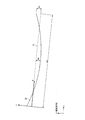
- the relationship between the standard deviation value D with respect to the linear approximation line C of the curve G and the pitch PL satisfies the following formula (1).
- this equation (1) is established for all the curves G constituting each curve group Gs.
- a linear approximation line C is obtained by using a well-known least square method.
- the direction of the linear approximation line C is taken as the X-axis
- the direction perpendicular to the X-axis is taken as the Y-axis
- the coordinate system is redrawn
- the X axis and the Y axis may be parallel to the x axis and the y axis, but depending on the shape of the curve G, the X axis and the Y axis may be inclined with respect to the x axis and the y axis as shown in FIG.
- the standard deviation value D is defined by the following formula (2).
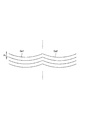
- the shape of the groove G in the present embodiment is not required to be a straight line, and it may be an arc shape as shown in FIG. 4A or a continuous smooth curve shape as shown in FIG. 4B. There are various types such as a straight section obtained by connecting a plurality of straight lines, but the warp deformation mechanism described above is unchanged, and the equivalent effect can be obtained by setting (D / PL) to 0.02 or more. Is obtained.
- the iron loss is less likely to decrease when the average value of the angle between the direction of the groove G and the direction orthogonal to the conveyance direction exceeds ⁇ 30 °. It is desirable that the average value of the angle formed by the direction perpendicular to the transport direction is within ⁇ 30 °. More specifically, when the angle formed between the tangent line of the curve G defined by each point on the curve G and the direction orthogonal to the transport direction is ⁇ (°), ⁇ represents the following formula (3): It is desirable to satisfy.
- the groove G (curve G) is smooth, and at all points on the groove G (curve G), it is possible to reduce the iron loss by making the angle made with the direction orthogonal to the conveying direction within ⁇ 30 °. More preferable from the viewpoint.
- the present embodiment uses a plurality of laser scanners by completely matching both ends of the curve in the curve group Gs1 and the curve G in the curve group Gs2. It is possible to obtain a curve group Gs in which one curve G is long connected. In this case, if the standard deviation value D with respect to the linear approximation line C obtained in the same manner as described above is set to the range of the equation (1) with respect to the curve G in a single connected range, the amount of warpage is small. A grain-oriented electrical steel sheet is obtained.
- FIG. 7 is a schematic diagram showing a cross-sectional shape of the steel plate 1 when the steel plate 1 is viewed from the plate width direction.
- a groove G is formed on the front surface 1a and the back surface 1b of the steel plate 1, and the position of the groove G (curve G) formed on the front surface 1a is the position of the groove G (curve G) formed on the back surface 1b. It is the same position as the position.
- the same position means not only the case where the position of the groove G on the front surface 1a and the position of the groove G on the back surface 1b coincide, but also two grooves G in at least one of the rolling direction and the sheet width direction. This means that even when the distance is shifted, the amount of shift is not more than the groove width of the groove G.
- the position of the curve G (groove G) formed on the front surface 1a and the back surface 1b of the steel plate 1 is the same, the position of the curve G formed on the front surface 1a and the back surface 1b of the steel plate 1 is not the same. Compared with, it becomes possible to further reduce the amount of warpage of the steel plate 1.
- the grain-oriented electrical steel sheet according to the present embodiment basically includes, for example, a silicon steel slab as a raw material, a hot rolling process, an annealing process, a cold rolling process, a decarburizing annealing process, a finish annealing process, a flatness. It is manufactured by adding a periodic groove forming step by laser irradiation to a general manufacturing process of a grain-oriented electrical steel sheet, which is performed in the order of a chemical annealing step and an insulating film forming step.
- Groove formation by laser irradiation is performed somewhere after the cold rolling process, before the insulating film forming process, or after the insulating film forming process.
- a case where groove formation by laser irradiation is performed after the planarization annealing process and before the insulating film forming process will be described as an example, but the same irradiation method as described below can be used in other processes.
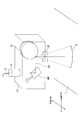
- FIG. 1 shows a laser light source and a laser scanner.
- the steel plate 1 is passed at a constant speed in the rolling direction (conveying direction) at a predetermined line speed VL.
- light output from a plurality of laser light sources LO1, LO2, and LO3 (hereinafter omitted) is respectively transmitted through a plurality of laser scanners LS1, LS2, It is transmitted to LS3 (hereinafter omitted).
- These laser scanners LS1, LS2, and LS3 irradiate the steel plate 1 with laser beams LB1, LB2, and LB3 (hereinafter omitted), so that the curve groups Gs1, Gs2, and Gs3 (hereinafter omitted) are formed. It is formed on the steel plate 1.
- a laser light source LO when it is not necessary to specify any of the laser light sources LO1, LO2, and LO3 (hereinafter omitted), they are collectively referred to as a laser light source LO.
- a laser scanner LS1, LS2, and LS3 when it is not necessary to specify any of the laser scanners LS1, LS2, and LS3 (hereinafter omitted), they are collectively referred to as a laser scanner LS.
- a laser beam LB when it is not necessary to specify any of the laser beams LB1, LB2, and LB3 (hereinafter omitted), they are collectively referred to as a laser beam LB.
- the laser light source LO it is preferable to use a laser light source having a wavelength of 0.4 to 2.1 ⁇ m and high condensing property, that is, a laser light source such as a fiber laser or a thin disk type YAG laser.
- a laser light source such as a fiber laser or a thin disk type YAG laser.
- FIG. 5A is a diagram illustrating an example of the configuration of the laser scanner LS.
- this laser scanner LS for example, a well-known galvano scanner can be used.
- a laser scanner LS includes a condensing lens 6 for condensing a laser beam LB emitted from a collimator 5 connected to a laser light source LO via an optical fiber 3, and a laser. It comprises two galvanometer mirrors GM1 and GM2 that reflect the beam LB. By adjusting the angles of these two galvanometer mirrors GM1 and GM2, the laser beam LB condensed by the condenser lens 6 can be scanned on the steel plate 1 at high speed.
- the laser beam LB is scanned mainly in the direction (plate width direction) orthogonal to the rolling direction by the rotation of the galvanometer mirror GM2.
- the rotation of the galvanometer mirror GM1 plays a role of creating a distance (amplitude) from the linear approximation line mainly by scanning in a direction perpendicular to the sheet width direction (that is, the rolling direction).
- the condenser lens 6 can be operated back and forth in the direction of the optical axis of the laser beam LB in order to correct a change in work distance that occurs according to the combination of the deflection angles of the two galvanometer mirrors GM1 and GM2. Yes.
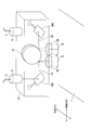
- the configuration of the laser scanner LS is not limited to the configuration shown in FIG. 5A, and any configuration that can draw the curve G (groove G) two-dimensionally in the steel plate 1 may be used.
- FIG. 5B a configuration in which one galvanometer mirror is combined with a polygon mirror as disclosed in Patent Document 5 is also conceivable.
- the laser beam LB is mainly scanned in the plate width direction by the rotation of the polygon mirror 10.
- the rotation of the galvanometer mirror GM1 plays a role of creating a separation (amplitude) from the linear approximation line mainly by scanning in the rolling direction.
- the f ⁇ lens 20 is used as a condenser lens.
- the focal point of the laser beam LB can be maintained on the steel plate 1. Further, for example, as shown in FIG. 5C, if a common polygon mirror 10 is used for the two laser beams LB, a plurality of lasers are formed in order to form the groove G in the entire plate width direction of the steel plate 1. When it is necessary to use the scanner LS, the number of laser scanners LS can be reduced, so that the entire manufacturing apparatus can be reduced in size.
- the width and depth of the groove G are determined by parameters such as the output of the laser beam LB, the scan speed, and the condensing shape. These parameters are adjusted so that the groove depth is 5 ⁇ m to 50 ⁇ m and the groove width is 10 ⁇ m to 300 ⁇ m.
- a time for performing one scan that is, laser irradiation is started from the start end of the scan width, laser scan is performed to the end of the scan width, and from the start end of the next scan
- the time T until laser irradiation is started is set as shown in the following formula (4).
- PL T ⁇ VL (4)
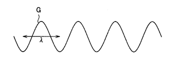
- FIG. 4C and 4D show examples of the shape of one curve G (groove G) obtained by scanning the laser beam LB from one laser scanner LS as the present embodiment.
- (D / PL) calculated from these curves G is the same, but as shown in FIG. 4C, if the wavelength ⁇ of one period of the curve G becomes too short, a high-speed scan is required in the conveyance direction, and the scanner May be limited by the maximum scan speed allowed.
- the wavelength ⁇ of the curve G is larger than that in FIG.
- the wavelength ⁇ of the curve G is suitable for industrial production.
- the cold-rolled material was decarburized and annealed under conditions of 800 ° C. ⁇ 2 minutes, and then an annealing separator mainly composed of magnesia was applied. And the cold rolled material which apply
- a steel plate 1 is a directional electromagnetic steel plate having a plate width of 1000 mm after finish annealing, made through the above-described process, and a glass film is formed on the surface of the ground iron.
- the steel plate 1 is passed at a constant speed in the rolling direction (conveying direction) at a line speed VL.
- the laser beam intensity P was 1000 W
- the focused beam diameter d was 0.04 mm
- the pitch PL was 5 mm.
- the speed at each moment has a direction along the tangent line of the curve G, but the magnitude of the speed projected on the linear approximation line was in the range of 8000 ⁇ 450 mm / s.
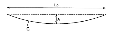
- the groove length Lc (see FIG. 2) determined by the scan width per scanner was 100 mm.
- the amplitude A was in the range of 55 ⁇ 5 ⁇ m and the groove depth was in the range of 15 ⁇ 3 ⁇ m.
- a groove was formed by pressing a mechanical tooth mold on the same steel plate material. At this time, the shape of the groove was a straight line, and the pitch PL was 5 mm. The groove width was 52 ⁇ m and the groove depth was 14 ⁇ m, and a groove having almost the same cross-sectional shape as the laser method was obtained.
- a space factor was measured based on JIS 2550. As described above, a large space factor means that the amount of warpage of the steel sheet 1 is reduced.
- Fig. 6 shows the measurement results of the space factor.
- the horizontal axis of the graph shown in FIG. 6 indicates (D / PL) obtained by the method described above, and the vertical axis indicates the space factor.
- the groove G obtained by the laser method has an inferior space factor compared to the mechanical straight groove.
- (D / PL) 0.02 or more, it can be seen that the space factor can be made larger than that of the mechanical type.
- the space factor is 96.5% or more
- (D / PL) is 0.1 or more
- the space factor is 97%. The above high value is shown.
- the warpage deformation amount of the steel sheet 1 can be reduced when the relationship between the standard deviation value D and the groove pitch PL satisfies the above-described formula (1). And by reducing the amount of warping deformation, when laminated and compressed as a core material of a wound transformer, the space factor is high and the performance as a transformer is high, and the effect of stress concentration is mitigated. Iron loss characteristics can be realized.
- the groove when the groove is formed on the surface of the steel sheet by laser beam irradiation, the deformation amount of the steel sheet due to the formation of the groove can be reduced. Therefore, when the groove is laminated and compressed as the iron core material of the winding transformer, In addition to a high volume factor and high performance as a transformer, the effect of stress concentration is mitigated, so that an electrical steel sheet having excellent iron loss characteristics can be provided.
Landscapes
- Chemical & Material Sciences (AREA)
- Engineering & Computer Science (AREA)
- Physics & Mathematics (AREA)
- Mechanical Engineering (AREA)
- Materials Engineering (AREA)
- Metallurgy (AREA)
- Organic Chemistry (AREA)
- Optics & Photonics (AREA)
- Crystallography & Structural Chemistry (AREA)
- Thermal Sciences (AREA)
- Manufacturing & Machinery (AREA)
- Electromagnetism (AREA)
- Plasma & Fusion (AREA)
- Dispersion Chemistry (AREA)
- Power Engineering (AREA)
- Manufacturing Of Steel Electrode Plates (AREA)
- Soft Magnetic Materials (AREA)
- Laser Beam Processing (AREA)
Priority Applications (9)
| Application Number | Priority Date | Filing Date | Title |
|---|---|---|---|
| JP2014512641A JP5935880B2 (ja) | 2012-04-27 | 2013-04-24 | 方向性電磁鋼板及びその製造方法 |
| US14/390,110 US10131018B2 (en) | 2012-04-27 | 2013-04-24 | Grain-oriented magnetic steel sheet and method of producing the same |
| CN201380019339.XA CN104203486B (zh) | 2012-04-27 | 2013-04-24 | 方向性电磁钢板及其制造方法 |
| BR112014025281-5A BR112014025281B1 (pt) | 2012-04-27 | 2013-04-24 | Chapa de aço magnético com grão orientado e método para produção da mesma |
| PL13782201T PL2843062T3 (pl) | 2012-04-27 | 2013-04-24 | Blacha cienka ze stali elektrotechnicznej o ziarnach zorientowanych oraz sposób jej wytwarzania |
| IN7669DEN2014 IN2014DN07669A (pl) | 2012-04-27 | 2013-04-24 | |
| RU2014140878/02A RU2605725C2 (ru) | 2012-04-27 | 2013-04-24 | Электротехническая листовая сталь с ориентированной зеренной структурой и способ ее изготовления |
| EP13782201.1A EP2843062B1 (en) | 2012-04-27 | 2013-04-24 | Grain-oriented electrical steel sheet and manufacturing method therefor |
| KR1020147028018A KR101681822B1 (ko) | 2012-04-27 | 2013-04-24 | 방향성 전자 강판 및 그 제조 방법 |
Applications Claiming Priority (2)
| Application Number | Priority Date | Filing Date | Title |
|---|---|---|---|
| JP2012-103212 | 2012-04-27 | ||
| JP2012103212 | 2012-04-27 |
Publications (1)
| Publication Number | Publication Date |
|---|---|
| WO2013161863A1 true WO2013161863A1 (ja) | 2013-10-31 |
Family
ID=49483171
Family Applications (1)
| Application Number | Title | Priority Date | Filing Date |
|---|---|---|---|
| PCT/JP2013/062029 WO2013161863A1 (ja) | 2012-04-27 | 2013-04-24 | 方向性電磁鋼板及びその製造方法 |
Country Status (10)
| Country | Link |
|---|---|
| US (1) | US10131018B2 (pl) |
| EP (1) | EP2843062B1 (pl) |
| JP (1) | JP5935880B2 (pl) |
| KR (1) | KR101681822B1 (pl) |
| CN (1) | CN104203486B (pl) |
| BR (1) | BR112014025281B1 (pl) |
| IN (1) | IN2014DN07669A (pl) |
| PL (1) | PL2843062T3 (pl) |
| RU (1) | RU2605725C2 (pl) |
| WO (1) | WO2013161863A1 (pl) |
Cited By (4)
| Publication number | Priority date | Publication date | Assignee | Title |
|---|---|---|---|---|
| JP2015140470A (ja) * | 2014-01-30 | 2015-08-03 | Jfeスチール株式会社 | 方向性電磁鋼板およびその製造方法 |
| US20170348802A1 (en) * | 2014-12-24 | 2017-12-07 | Posco | Method for forming groove in surface of steel plate, and apparatus therefor |
| WO2019164012A1 (ja) * | 2018-02-26 | 2019-08-29 | 日本製鉄株式会社 | 方向性電磁鋼板 |
| JPWO2020230816A1 (pl) * | 2019-05-14 | 2020-11-19 |
Families Citing this family (20)
| Publication number | Priority date | Publication date | Assignee | Title |
|---|---|---|---|---|
| US10793929B2 (en) * | 2013-07-24 | 2020-10-06 | Posco | Grain-oriented electrical steel sheet and method for manufacturing same |
| KR101719231B1 (ko) * | 2014-12-24 | 2017-04-04 | 주식회사 포스코 | 방향성 전기강판 및 그 제조방법 |
| CN107208223B (zh) * | 2015-04-20 | 2019-01-01 | 新日铁住金株式会社 | 方向性电磁钢板 |
| PL3287533T3 (pl) * | 2015-04-20 | 2020-07-27 | Nippon Steel Corporation | Blacha ze zorientowanej stali magnetycznej |
| US20190009370A1 (en) * | 2016-01-22 | 2019-01-10 | Tata Steel Nederland Technology B.V. | Laser texturing of steel strip |
| WO2017171013A1 (ja) * | 2016-03-31 | 2017-10-05 | 新日鐵住金株式会社 | 方向性電磁鋼板 |
| KR101944899B1 (ko) * | 2016-12-22 | 2019-02-01 | 주식회사 포스코 | 방향성 전기강판의 자구미세화 방법 |
| JP6372581B1 (ja) * | 2017-02-17 | 2018-08-15 | Jfeスチール株式会社 | 方向性電磁鋼板 |
| CN108660295A (zh) * | 2017-03-27 | 2018-10-16 | 宝山钢铁股份有限公司 | 一种低铁损取向硅钢及其制造方法 |
| KR102044325B1 (ko) * | 2017-12-21 | 2019-11-13 | 주식회사 포스코 | 변압기 철심 가공장치 및 변압기 철심 가공방법 |
| JP7028242B2 (ja) * | 2018-01-31 | 2022-03-02 | Jfeスチール株式会社 | 方向性電磁鋼板およびこれを用いてなる変圧器の巻鉄心並びに巻鉄心の製造方法 |
| WO2019151397A1 (ja) * | 2018-01-31 | 2019-08-08 | 日本製鉄株式会社 | 方向性電磁鋼板 |
| WO2020075470A1 (ja) * | 2018-10-09 | 2020-04-16 | 株式会社Ihi | Sm-Fe-N磁石の製造方法、Sm-Fe-N磁石及びSm-Fe-N磁石を備えるモータ |
| EP3970904B1 (en) * | 2019-05-14 | 2023-06-21 | Nippon Steel Corporation | Groove processing device and groove processing method |
| CN110358896A (zh) * | 2019-05-23 | 2019-10-22 | 江苏北辰互邦电力股份有限公司 | 一种高磁感变压器用取向硅钢生产用脱碳退火工艺 |
| JP7056758B2 (ja) * | 2019-07-31 | 2022-04-19 | Jfeスチール株式会社 | 線状溝形成方法および線状溝形成装置ならびに方向性電磁鋼板の製造方法 |
| KR102395230B1 (ko) * | 2019-12-20 | 2022-05-04 | 주식회사 포스코 | 방향성 전기강판 및 그 자구미세화 방법 |
| KR102428854B1 (ko) * | 2019-12-20 | 2022-08-02 | 주식회사 포스코 | 방향성 전기강판 및 그 자구미세화 방법 |
| CN114762911B (zh) * | 2021-01-11 | 2023-05-09 | 宝山钢铁股份有限公司 | 一种低磁致伸缩取向硅钢及其制造方法 |
| KR20240098885A (ko) * | 2022-12-21 | 2024-06-28 | 주식회사 포스코 | 방향성 전기강판 및 그의 제조 방법 |
Citations (11)
| Publication number | Priority date | Publication date | Assignee | Title |
|---|---|---|---|---|
| JPS5826406B2 (ja) | 1979-10-03 | 1983-06-02 | 新日本製鐵株式会社 | 電磁鋼板の鉄損値を改善する方法及びその装置 |
| JPS6253579B2 (pl) | 1984-11-10 | 1987-11-11 | Nippon Steel Corp | |
| JPS6254873B2 (pl) | 1984-11-10 | 1987-11-17 | Nippon Steel Corp | |
| JPH0657335A (ja) | 1992-08-07 | 1994-03-01 | Nippon Steel Corp | パルスco2レーザを用いた方向性電磁鋼板の鉄損改善方法および装置 |
| JPH06136449A (ja) * | 1992-10-23 | 1994-05-17 | Kawasaki Steel Corp | 低鉄損一方向性珪素鋼板の製造方法 |
| JPH06299244A (ja) * | 1993-04-12 | 1994-10-25 | Kawasaki Steel Corp | 磁気特性に優れた電磁鋼板の製造方法 |
| JPH0748626A (ja) * | 1992-11-17 | 1995-02-21 | Allegheny Internatl Inc | 局部機械的変形による電気鋼の磁区調質方法及び装置 |
| JPH0748627A (ja) * | 1992-11-17 | 1995-02-21 | Allegheny Internatl Inc | 機械的調質磁区壁スペースを有するケイ素鋼ストリップ |
| JP2000109961A (ja) * | 1998-10-06 | 2000-04-18 | Nippon Steel Corp | 磁気特性の優れた一方向性電磁鋼板とその製造方法 |
| WO2011125672A1 (ja) | 2010-04-01 | 2011-10-13 | 新日本製鐵株式会社 | 方向性電磁鋼板及びその製造方法 |
| JP2012057232A (ja) * | 2010-09-10 | 2012-03-22 | Jfe Steel Corp | 方向性電磁鋼板およびその製造方法 |
Family Cites Families (12)
| Publication number | Priority date | Publication date | Assignee | Title |
|---|---|---|---|---|
| JPS5826406A (ja) | 1981-08-10 | 1983-02-16 | 松下電器産業株式会社 | 乳白板付照明器具 |
| GB2168626B (en) | 1984-11-10 | 1987-12-23 | Nippon Steel Corp | Grain-oriented electrical steel sheet having stable magnetic properties resistant to stress-relief annealing, and method and apparatus for producing the same |
| JPS6254873A (ja) | 1985-09-03 | 1987-03-10 | Sanyo Electric Co Ltd | 固定ヘツド型デイジタル磁気再生装置 |
| JPS6253579A (ja) | 1985-09-03 | 1987-03-09 | Seiko Epson Corp | 携帯用受信機器 |
| SU1744128A1 (ru) | 1990-04-04 | 1992-06-30 | Институт физики металлов Уральского отделения АН СССР | Способ изготовлени анизотропной электротехнической стали |
| KR930007313B1 (ko) | 1990-08-01 | 1993-08-05 | 가와사끼세이데쓰 가부시끼가이샤 | 저 철손 방향성 전자강판의 제조방법 |
| US5296051A (en) * | 1993-02-11 | 1994-03-22 | Kawasaki Steel Corporation | Method of producing low iron loss grain-oriented silicon steel sheet having low-noise and superior shape characteristics |
| KR960005227B1 (ko) | 1993-11-11 | 1996-04-23 | 포항종합제철주식회사 | 자구미세화에 의한 방향성 전기강판의 철손개선방법 및 자구미세화 장치 |
| EP0870843A1 (en) | 1995-12-27 | 1998-10-14 | Nippon Steel Corporation | Magnetic steel sheet having excellent magnetic properties and method for manufacturing the same |
| JP5919617B2 (ja) | 2010-08-06 | 2016-05-18 | Jfeスチール株式会社 | 方向性電磁鋼板およびその製造方法 |
| WO2012033197A1 (ja) * | 2010-09-09 | 2012-03-15 | 新日本製鐵株式会社 | 方向性電磁鋼板及びその製造方法 |
| WO2013094218A1 (ja) | 2011-12-22 | 2013-06-27 | Jfeスチール株式会社 | 方向性電磁鋼板およびその製造方法 |
-
2013
- 2013-04-24 BR BR112014025281-5A patent/BR112014025281B1/pt active IP Right Grant
- 2013-04-24 EP EP13782201.1A patent/EP2843062B1/en active Active
- 2013-04-24 CN CN201380019339.XA patent/CN104203486B/zh active Active
- 2013-04-24 IN IN7669DEN2014 patent/IN2014DN07669A/en unknown
- 2013-04-24 US US14/390,110 patent/US10131018B2/en active Active
- 2013-04-24 JP JP2014512641A patent/JP5935880B2/ja active Active
- 2013-04-24 RU RU2014140878/02A patent/RU2605725C2/ru active
- 2013-04-24 PL PL13782201T patent/PL2843062T3/pl unknown
- 2013-04-24 WO PCT/JP2013/062029 patent/WO2013161863A1/ja active Application Filing
- 2013-04-24 KR KR1020147028018A patent/KR101681822B1/ko active IP Right Grant
Patent Citations (11)
| Publication number | Priority date | Publication date | Assignee | Title |
|---|---|---|---|---|
| JPS5826406B2 (ja) | 1979-10-03 | 1983-06-02 | 新日本製鐵株式会社 | 電磁鋼板の鉄損値を改善する方法及びその装置 |
| JPS6253579B2 (pl) | 1984-11-10 | 1987-11-11 | Nippon Steel Corp | |
| JPS6254873B2 (pl) | 1984-11-10 | 1987-11-17 | Nippon Steel Corp | |
| JPH0657335A (ja) | 1992-08-07 | 1994-03-01 | Nippon Steel Corp | パルスco2レーザを用いた方向性電磁鋼板の鉄損改善方法および装置 |
| JPH06136449A (ja) * | 1992-10-23 | 1994-05-17 | Kawasaki Steel Corp | 低鉄損一方向性珪素鋼板の製造方法 |
| JPH0748626A (ja) * | 1992-11-17 | 1995-02-21 | Allegheny Internatl Inc | 局部機械的変形による電気鋼の磁区調質方法及び装置 |
| JPH0748627A (ja) * | 1992-11-17 | 1995-02-21 | Allegheny Internatl Inc | 機械的調質磁区壁スペースを有するケイ素鋼ストリップ |
| JPH06299244A (ja) * | 1993-04-12 | 1994-10-25 | Kawasaki Steel Corp | 磁気特性に優れた電磁鋼板の製造方法 |
| JP2000109961A (ja) * | 1998-10-06 | 2000-04-18 | Nippon Steel Corp | 磁気特性の優れた一方向性電磁鋼板とその製造方法 |
| WO2011125672A1 (ja) | 2010-04-01 | 2011-10-13 | 新日本製鐵株式会社 | 方向性電磁鋼板及びその製造方法 |
| JP2012057232A (ja) * | 2010-09-10 | 2012-03-22 | Jfe Steel Corp | 方向性電磁鋼板およびその製造方法 |
Cited By (12)
| Publication number | Priority date | Publication date | Assignee | Title |
|---|---|---|---|---|
| JP2015140470A (ja) * | 2014-01-30 | 2015-08-03 | Jfeスチール株式会社 | 方向性電磁鋼板およびその製造方法 |
| US20170348802A1 (en) * | 2014-12-24 | 2017-12-07 | Posco | Method for forming groove in surface of steel plate, and apparatus therefor |
| EP3238870A4 (en) * | 2014-12-24 | 2018-02-21 | Posco | Method for forming groove in surface of steel plate, and apparatus therefor |
| JP2018507111A (ja) * | 2014-12-24 | 2018-03-15 | ポスコPosco | 鋼板表面の溝形成方法およびその装置 |
| WO2019164012A1 (ja) * | 2018-02-26 | 2019-08-29 | 日本製鉄株式会社 | 方向性電磁鋼板 |
| JP6614398B1 (ja) * | 2018-02-26 | 2019-12-04 | 日本製鉄株式会社 | 方向性電磁鋼板 |
| RU2765033C1 (ru) * | 2018-02-26 | 2022-01-24 | Ниппон Стил Корпорейшн | Электротехнический стальной лист с ориентированной зеренной структурой |
| US11393612B2 (en) | 2018-02-26 | 2022-07-19 | Nippon Steel Corporation | Grain-oriented electrical steel sheet |
| JPWO2020230816A1 (pl) * | 2019-05-14 | 2020-11-19 | ||
| CN113825589A (zh) * | 2019-05-14 | 2021-12-21 | 日本制铁株式会社 | 槽加工装置以及槽加工方法 |
| JP7332940B2 (ja) | 2019-05-14 | 2023-08-24 | 日本製鉄株式会社 | 溝加工装置及び溝加工方法 |
| CN113825589B (zh) * | 2019-05-14 | 2024-03-29 | 日本制铁株式会社 | 槽加工装置以及槽加工方法 |
Also Published As
| Publication number | Publication date |
|---|---|
| US20150059932A1 (en) | 2015-03-05 |
| RU2014140878A (ru) | 2016-06-20 |
| JPWO2013161863A1 (ja) | 2015-12-24 |
| KR101681822B1 (ko) | 2016-12-01 |
| KR20140133599A (ko) | 2014-11-19 |
| JP5935880B2 (ja) | 2016-06-15 |
| EP2843062A1 (en) | 2015-03-04 |
| US10131018B2 (en) | 2018-11-20 |
| IN2014DN07669A (pl) | 2015-05-15 |
| CN104203486A (zh) | 2014-12-10 |
| PL2843062T3 (pl) | 2020-12-14 |
| BR112014025281B1 (pt) | 2019-06-18 |
| RU2605725C2 (ru) | 2016-12-27 |
| EP2843062A4 (en) | 2015-12-30 |
| CN104203486B (zh) | 2016-08-24 |
| EP2843062B1 (en) | 2020-07-29 |
Similar Documents
| Publication | Publication Date | Title |
|---|---|---|
| JP5935880B2 (ja) | 方向性電磁鋼板及びその製造方法 | |
| JP5234222B2 (ja) | 方向性電磁鋼板及びその製造方法 | |
| RU2509814C1 (ru) | Электротехническая листовая сталь с ориентированными зернами и способ ее производства | |
| JP6200908B2 (ja) | 方向性電磁鋼板の製造方法 | |
| KR101719231B1 (ko) | 방향성 전기강판 및 그 제조방법 | |
| JP7010311B2 (ja) | 方向性電磁鋼板 | |
| JP6638599B2 (ja) | 巻鉄芯、及び巻鉄芯の製造方法 | |
| US9607744B2 (en) | Laser processing apparatus and laser irradiation method | |
| JP7027923B2 (ja) | 方向性電磁鋼板、巻鉄芯、方向性電磁鋼板の製造方法、及び、巻鉄芯の製造方法 | |
| JP6838321B2 (ja) | 方向性電磁鋼板の製造方法、及び方向性電磁鋼板 | |
| RU2765033C1 (ru) | Электротехнический стальной лист с ориентированной зеренной структурой | |
| JP7406064B2 (ja) | 方向性電磁鋼板の製造方法及び巻鉄芯の製造方法 | |
| JP2021025072A (ja) | 方向性電磁鋼板、巻鉄芯、方向性電磁鋼板の製造方法、及び、巻鉄芯の製造方法 | |
| JP2005340619A (ja) | 巻き鉄芯およびそれを用いた変圧器 | |
| JP7372520B2 (ja) | 方向性電磁鋼板、巻鉄芯、方向性電磁鋼板の製造方法、及び、巻鉄芯の製造方法 |
Legal Events
| Date | Code | Title | Description |
|---|---|---|---|
| 121 | Ep: the epo has been informed by wipo that ep was designated in this application |
Ref document number: 13782201 Country of ref document: EP Kind code of ref document: A1 |
|
| ENP | Entry into the national phase |
Ref document number: 2014512641 Country of ref document: JP Kind code of ref document: A |
|
| WWE | Wipo information: entry into national phase |
Ref document number: 2013782201 Country of ref document: EP |
|
| WWE | Wipo information: entry into national phase |
Ref document number: 14390110 Country of ref document: US |
|
| ENP | Entry into the national phase |
Ref document number: 20147028018 Country of ref document: KR Kind code of ref document: A |
|
| NENP | Non-entry into the national phase |
Ref country code: DE |
|
| ENP | Entry into the national phase |
Ref document number: 2014140878 Country of ref document: RU Kind code of ref document: A |
|
| REG | Reference to national code |
Ref country code: BR Ref legal event code: B01A Ref document number: 112014025281 Country of ref document: BR |
|
| ENP | Entry into the national phase |
Ref document number: 112014025281 Country of ref document: BR Kind code of ref document: A2 Effective date: 20141010 |