WO2013161221A1 - 車両用超音波センサ装置及び車両用超音波センサ装置の組み付け方法 - Google Patents
車両用超音波センサ装置及び車両用超音波センサ装置の組み付け方法 Download PDFInfo
- Publication number
- WO2013161221A1 WO2013161221A1 PCT/JP2013/002597 JP2013002597W WO2013161221A1 WO 2013161221 A1 WO2013161221 A1 WO 2013161221A1 JP 2013002597 W JP2013002597 W JP 2013002597W WO 2013161221 A1 WO2013161221 A1 WO 2013161221A1
- Authority
- WO
- WIPO (PCT)
- Prior art keywords
- bumper
- ultrasonic sensor
- hole
- holding member
- vehicle
- Prior art date
- Legal status (The legal status is an assumption and is not a legal conclusion. Google has not performed a legal analysis and makes no representation as to the accuracy of the status listed.)
- Ceased
Links
Images

Classifications
-
- G—PHYSICS
- G01—MEASURING; TESTING
- G01S—RADIO DIRECTION-FINDING; RADIO NAVIGATION; DETERMINING DISTANCE OR VELOCITY BY USE OF RADIO WAVES; LOCATING OR PRESENCE-DETECTING BY USE OF THE REFLECTION OR RERADIATION OF RADIO WAVES; ANALOGOUS ARRANGEMENTS USING OTHER WAVES
- G01S7/00—Details of systems according to groups G01S13/00, G01S15/00, G01S17/00
- G01S7/52—Details of systems according to groups G01S13/00, G01S15/00, G01S17/00 of systems according to group G01S15/00
- G01S7/521—Constructional features
-
- B—PERFORMING OPERATIONS; TRANSPORTING
- B60—VEHICLES IN GENERAL
- B60R—VEHICLES, VEHICLE FITTINGS, OR VEHICLE PARTS, NOT OTHERWISE PROVIDED FOR
- B60R19/00—Wheel guards; Radiator guards, e.g. grilles; Obstruction removers; Fittings damping bouncing force in collisions
- B60R19/02—Bumpers, i.e. impact receiving or absorbing members for protecting vehicles or fending off blows from other vehicles or objects
- B60R19/48—Bumpers, i.e. impact receiving or absorbing members for protecting vehicles or fending off blows from other vehicles or objects combined with, or convertible into, other devices or objects, e.g. bumpers combined with road brushes, bumpers convertible into beds
- B60R19/483—Bumpers, i.e. impact receiving or absorbing members for protecting vehicles or fending off blows from other vehicles or objects combined with, or convertible into, other devices or objects, e.g. bumpers combined with road brushes, bumpers convertible into beds with obstacle sensors of electric or electronic type
-
- G—PHYSICS
- G10—MUSICAL INSTRUMENTS; ACOUSTICS
- G10K—SOUND-PRODUCING DEVICES; METHODS OR DEVICES FOR PROTECTING AGAINST, OR FOR DAMPING, NOISE OR OTHER ACOUSTIC WAVES IN GENERAL; ACOUSTICS NOT OTHERWISE PROVIDED FOR
- G10K11/00—Methods or devices for transmitting, conducting or directing sound in general; Methods or devices for protecting against, or for damping, noise or other acoustic waves in general
- G10K11/004—Mounting transducers, e.g. provided with mechanical moving or orienting device
-
- G—PHYSICS
- G01—MEASURING; TESTING
- G01S—RADIO DIRECTION-FINDING; RADIO NAVIGATION; DETERMINING DISTANCE OR VELOCITY BY USE OF RADIO WAVES; LOCATING OR PRESENCE-DETECTING BY USE OF THE REFLECTION OR RERADIATION OF RADIO WAVES; ANALOGOUS ARRANGEMENTS USING OTHER WAVES
- G01S15/00—Systems using the reflection or reradiation of acoustic waves, e.g. sonar systems
- G01S15/88—Sonar systems specially adapted for specific applications
- G01S15/93—Sonar systems specially adapted for specific applications for anti-collision purposes
- G01S15/931—Sonar systems specially adapted for specific applications for anti-collision purposes of land vehicles
- G01S2015/937—Sonar systems specially adapted for specific applications for anti-collision purposes of land vehicles sensor installation details
- G01S2015/938—Sonar systems specially adapted for specific applications for anti-collision purposes of land vehicles sensor installation details in the bumper area
Definitions
- the present disclosure relates to a vehicle ultrasonic sensor device and a method for assembling the vehicle ultrasonic sensor device.
- Patent Document 1 a holding member having a pipe part is attached to the inside of a vehicle bumper where a through hole is formed by bonding or the like, and then an ultrasonic sensor module is inserted into the pipe part of the holding member.
- a technique for assembling an ultrasonic sensor module to a vehicle bumper is disclosed. If it does in this way, even if a holding member is attached, since the external design of a vehicle bumper does not change, design nature does not fall.
- Patent Document 1 discloses that the ultrasonic sensor is inserted into the through-hole of the vehicle bumper until the head of the module of the ultrasonic sensor is positioned substantially flush with the outer surface of the vehicle bumper. Is also disclosed.
- a surface other than the surface in the direction to be sensed among a plurality of surfaces of the ultrasonic transducer provided in the ultrasonic sensor Is known to be covered with a vibration isolating member that suppresses vibration.
- the present disclosure has been made in view of the above points, and an object of the present disclosure is to obtain a good appearance when an ultrasonic sensor is inserted into a through-hole provided in a vehicle bumper and is assembled to the vehicle bumper. It is another object of the present invention to provide an ultrasonic sensor device for a vehicle and an assembling method of the ultrasonic sensor device for a vehicle that facilitate the assembly.
- the vehicle ultrasonic sensor device includes an ultrasonic sensor including an ultrasonic transducer, and a holding member that houses the ultrasonic sensor.
- the ultrasonic sensor is attached to a predetermined part of a bumper of a vehicle, and the bumper has an outer surface exposed to the outside and an inner surface located on the opposite side of the outer surface.
- a predetermined portion of the bumper is provided with a bumper hole penetrating the bumper in a tip direction that is a direction from the inner surface toward the outer surface.
- the first portion of the ultrasonic sensor is accommodated in the bumper hole.
- the inner surface of the bumper has a contact surface that contacts a surface of the holding member that faces the inner surface of the bumper.
- the holding member is provided with a holding member hole penetrating the holding member in the distal direction.
- the second portion of the ultrasonic sensor is accommodated in the holding member hole.
- the holding member is made of an elastic material, and is integrated with a vibration isolating member that covers at least a part of a side surface of the ultrasonic sensor in a state where the second portion of the ultrasonic sensor is accommodated in the holding member hole.
- the vibration isolating member has a protruding end protruding in the tip direction. The protruding end portion protrudes in the tip direction from the contact surface of the bumper so as to fit into the bumper hole.
- a method of assembling the vehicle ultrasonic sensor device according to the first aspect on an inner surface of a bumper of the vehicle provided with a through-hole includes a protrusion of the vibration isolation member integrated with the holding member.
- the holding member is attached so that the end portion is fitted into the bumper hole, and the surface of the holding member facing the inner surface of the bumper is in contact with the inner surface of the bumper, and the vibration surface of the ultrasonic sensor is the bumper.
- the ultrasonic sensor is housed in the holding member hole until it is positioned substantially in the same plane as the outer surface of the holding member.
- the assembly is performed while obtaining a good appearance. Will also be easier.
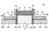
- FIG. 1 is a partial cross-sectional view illustrating a schematic configuration of an ultrasonic sensor device according to Embodiment 1 of the present disclosure.
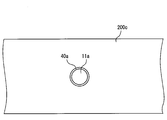
- FIG. 2 is a schematic diagram showing the outer shape of the bumper outer surface, the vibration surface of the ultrasonic transducer, and the protruding end portion of the outer peripheral surface vibration isolation member.
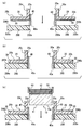
- FIGS. 3A to 3C are schematic diagrams for explaining a method of assembling the ultrasonic sensor device to the vehicle bumper.
- FIG. 4 is a partial cross-sectional view illustrating a schematic configuration of the ultrasonic sensor device according to the second embodiment of the present disclosure.
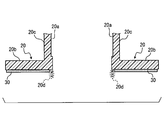
- FIG. 5 is a partial cross-sectional view for explaining a retainer protruding end of the retainer according to the second embodiment.
- FIG. 1 is a partial cross-sectional view illustrating a schematic configuration of an ultrasonic sensor device 100 according to the first embodiment.
- the ultrasonic sensor device 100 includes an ultrasonic sensor 10, a retainer 20, a double-sided tape 30, an outer peripheral surface vibration isolation member 40, and a case 50.
- the ultrasonic sensor device 100 operates as the vehicle ultrasonic sensor device according to the present disclosure.
- the ultrasonic sensor 10 includes an ultrasonic transducer 11 that transmits ultrasonic waves and receives ultrasonic waves reflected by an obstacle and a back surface vibration isolation member 12.
- the ultrasonic transducer 11 is provided by a microphone.
- the ultrasonic sensor 10 is assembled to a predetermined part of the vehicle bumper 200 and used as, for example, a back sonar or a corner sonar.
- the ultrasonic sensor 10 may be configured using a known sensor.
- Vehicle bumper 200 has an outer surface 200c exposed to the outside and an inner surface 200b located on the opposite side of outer surface 200c.
- an extension line along a distance (bumper thickness) from the outer surface 200c of the bumper to the inner surface 200b at a predetermined portion of the bumper 200 to which the ultrasonic sensor 10 is attached is referred to as a reference axis. That is, if the outer surface 200c and the inner surface 200b of the bumper 200 are substantially parallel at a predetermined portion, the reference axis is orthogonal to the outer surface 200c and the inner surface 200b.
- the direction toward the outside with respect to the vehicle along the reference axis is referred to as an outside direction
- the direction toward the inside with respect to the vehicle is referred to as an inside direction (or back side direction).
- the direction from the inner surface 200b of the bumper toward the outer surface 200c is also the direction toward the end with respect to the vehicle, it is also referred to as the tip direction.
- the housing of the microphone 11 is formed of a member made conductive by forming a conductive film on the surface of a metal material or an insulating material.
- the housing of the microphone 11 is formed of aluminum, and the vibration surface 11a is circular.
- the back vibration isolating member 12 is a vibration isolating elastic body for reducing vibration generated in the microphone 11.
- the back vibration isolator 12 for example, rubber such as silicon rubber may be used.
- the back vibration isolating member 12 is bonded to the ultrasonic sensor 10 with, for example, a silicon-based adhesive so as to cover the surface of the microphone 11 opposite to the vibration surface 10a.
- the retainer 20 is attached to an inner surface 200b of a vehicle bumper 200 provided with a through hole (hereinafter referred to as a bumper hole) 200a formed along a reference axis, and holds the ultrasonic sensor 10 in a predetermined position with respect to the vehicle bumper 200. It is a member to do.
- the retainer 20 functions as a holding member.
- the retainer 20 is formed of a material having a lower elastic modulus than the outer peripheral surface vibration-proof member 40.
- the retainer 20 may be formed of a resin such as polybutylene terephthalate (PBT).
- the retainer 20 is roughly composed of a plate-like portion 20b that faces the inner surface 200b of the vehicle bumper 200 and a cylindrical portion 20c that protrudes inward along the reference axis from the plate-like portion 20b.
- a part of the ultrasonic sensor 10 is accommodated in a through hole (hereinafter, retainer hole 20a) provided in the cylindrical portion 20c along the reference axis.
- retainer hole 20a As shown in FIG. 1, in a state where the ultrasonic sensor 10 is attached to a predetermined part of the bumper 200 of the vehicle, a part (first part) is accommodated in the bumper hole 200 and the other part (second part) is a retainer. It is stored in the hole 20a.
- the retainer hole 20a functions as a holding member hole.
- the central axis of the retainer hole 20a is orthogonal to the inner surface (hereinafter referred to as the bumper inner surface) 200b of the vehicle bumper 200. Further, the fitting direction of the protruding end portion 40a of the outer peripheral surface vibration-proofing member 40, which will be described later, into the bumper hole 200a is substantially parallel to the reference axis. Moreover, the attachment direction which is a direction which attaches the retainer 20 to the bumper 200 has faced the outer side direction (front-end
- the double-sided tape 30 is a fixing member for fixing the retainer 20 to the vehicle bumper 200.
- the double-sided tape 30 may be configured to be bonded in advance to the surface of the plate-like portion 20b of the retainer 20 that faces the bumper inner surface 200b of the vehicle bumper 200 in advance.
- the retainer 20 may be fixed to the vehicle bumper 200 with an adhesive or the like, or the retainer 20 may be fixed to the vehicle bumper 200 by welding or spray bonding.
- the outer peripheral surface vibration-proof member 40 is a vibration-proof elastic body for reducing vibration generated in the ultrasonic vibrator 11 of the ultrasonic sensor 10.
- the outer peripheral surface vibration-proofing member 40 for example, rubber such as silicon rubber may be used.
- the same material as the back surface anti-vibration member 12 may be used, or a different material may be used.
- the outer peripheral surface vibration isolation member 40 is integrally formed with the retainer 20 (for example, insert molding or two-color molding) on the inner peripheral surface of the retainer hole 20a. More specifically, the outer peripheral surface vibration isolation member 40 is provided so as to cover the outer periphery (in other words, the side surface) in the radial direction of the retainer hole 20a in the microphone 11 when the ultrasonic sensor 10 is accommodated in the retainer hole 20a. .
- the outer peripheral surface vibration-proof member 40 suppresses vibrations on the side surface of the ultrasonic sensor 10.
- the conventional technology has integrated a vibration isolating member such as silicon rubber on the side surface of the ultrasonic sensor 10 by bonding or the like.
- the vibration isolating member is not integrated on the side surface of the ultrasonic sensor 10, and the outer peripheral surface vibration isolating member 40 is integrated on the retainer 20 side.
- the vibration isolating member may not be integrated over the entire side surface of the ultrasonic sensor 10, or the vibration isolating member may not be integrated with a part of the side surface of the ultrasonic sensor 10. That is, the vibration isolating member that covers the entire side surface of the ultrasonic sensor 10 or at least a part of the side surface is integrated with the retainer 20.
- the vibration isolating member is not integrated with a part of the side surface of the ultrasonic sensor 10
- the retainer is located in a region corresponding to the vibration isolating member. About the 20 side area
- the outer peripheral surface vibration-proof member 40 protrudes outward along the reference axis from the surface of the retainer 20 that contacts the vehicle bumper 200 so as to contact and fit the opening edge of the bumper hole 200a. Is provided. That is, it protrudes along the direction in which the retainer 20 is attached to the vehicle bumper 200.
- a surface that contacts the retainer 20 is referred to as a contact surface.
- the outer peripheral surface vibration isolation member 40 functions as a vibration isolation member.
- the hole shape and diameter of the retainer hole 20a and the hole shape and diameter of the bumper hole 200a are provided substantially the same, and the outer peripheral surface vibration isolation member 40 extends along the inner peripheral surface of the retainer hole 20a.
- the bumper extends from the contact surface of the bumper so as to protrude in the mounting direction.
- the portion of the outer peripheral surface vibration isolation member 40 that protrudes in the mounting direction from the bumper contact surface is hereinafter referred to as a protruding end portion 40a.
- the bumper contact surface described above is, in other words, the surface of the plate-like portion of the retainer 20 that faces the inner surface 200b of the vehicle bumper 200.
- the tip of the protruding end 40 a is the outer surface of the vehicle bumper 200.
- bumper outer surface 200c is provided so as to be substantially in the same plane.
- the retainer hole 20a has a predetermined length on the side opposite to the mounting direction of the retainer hole 20a. It is provided halfway.
- the present invention is not necessarily limited thereto.
- the case 50 is a housing to which the ultrasonic sensor 10 is assembled.
- the case 50 When roughly classified, the case 50 is roughly opened in a substantially box-shaped main body portion in which a circuit board (not shown) is accommodated and a bottom surface portion of the box body of the main body portion. It consists of an opening that protrudes in a cylindrical shape on the side and into which the ultrasonic sensor 10 is assembled. In FIG. 1, for convenience, only a part of the opening of the case 50 is illustrated.
- the ultrasonic sensor 10 is assembled to the case 50 by being lightly press-fitted into the opening of the case 50 with the back vibration-proof member 12 at the top.
- the case 50 has a structure that is fixed when the ultrasonic sensor 10 is inserted into the opening by a certain amount.
- the hole shape and the diameter of the outer periphery of the opening of the case 50 are provided in substantially the same shape and diameter as the retainer hole 20a.
- the outer peripheral surface vibration-proof member 40 provided partway through the retainer hole 20a and the opening of the case 50 that is fixed when a certain amount of the ultrasonic sensor 10 is inserted are provided so as to satisfy the following conditions. It has been. Specifically, when the tip of the opening of the case 50 with the ultrasonic sensor 10 assembled is inserted into the retainer hole 20a of the retainer 20 fitted to the bumper hole 200a with the protruding end 40a fitted into the bumper hole 200a.
- the vibration surface 11a of the microphone 11 that is, the vibration surface of the ultrasonic sensor 10) 11a is provided so as to be positioned substantially in the same plane as the bumper outer surface 200c.
- the ultrasonic sensor device 100 configured as described above is used by being fixed in a state where a part of the ultrasonic sensor 10 is disposed inside the bumper hole 200a so that sensing can be performed via the bumper hole 200a. . That is, the ultrasonic sensor device 100 can transmit and receive ultrasonic waves without using the vehicle bumper 200.
- the bumper outer surface 200c and the vibration surface 11a of the ultrasonic transducer 11 are located on substantially the same plane.
- the outer shape of the bumper outer surface 200c and the vibration surface 11a of the ultrasonic transducer 11 are in a concentric relationship as shown in FIG.
- the protruding end portion 40a of the outer peripheral surface vibration-proof member 40 is located on substantially the same plane, and the respective outer shapes are It is a concentric relationship.
- the retainer 20 is first attached to the vehicle bumper 200 provided with the bumper hole 200a.
- the front end of the protruding end portion 40a of the outer circumferential surface vibration-proof member 40 is inserted into the bumper hole 200a from the inner surface 200b of the vehicle bumper 200 in the outer direction (front end direction) along the reference axis (FIG. 3). (See (a)).
- the protruding end 40a of the outer peripheral surface vibration-proof member 40 is elastically deformed, the protruding end 40a can be press-fitted toward the outer surface 200c of the vehicle bumper 200 in a state where the protruding end 40a is in contact with the inner wall of the bumper hole 200a.
- the projecting end portion 40a is pushed into the bumper hole 200a in the outward direction (front end direction) along the reference axis. Then, the double-sided tape 30 adhered to the bumper contact surface is also adhered to the bumper inner surface 200b, and the retainer 20 is fixed to the vehicle bumper 200 (see FIG. 3B). The process so far corresponds to a holding member attaching process.
- the tip of the opening of the case 50 with the ultrasonic sensor 10 assembled is inserted into the retainer hole 20a of the retainer 20. That is, the ultrasonic sensor 10 is inserted into the retainer hole 20a of the retainer 20 in the outward direction (front end direction) along the reference axis with the vibration surface 11a at the head (see FIG. 3C).
- the tip of the opening of the case 50 is a retainer with the vehicle bumper outer surface 200c, the vibration surface 11a of the ultrasonic sensor 10 and the protruding end portion 40a of the outer peripheral surface vibration-proof member 40 positioned substantially in the same plane.
- the ultrasonic sensor 10 is held at a predetermined position by being hooked and fixed to the outer peripheral surface vibration isolation member 40 provided halfway through the hole 20a (see FIG. 1). That is, the ultrasonic sensor 10 is fixed to the vehicle bumper 200. This process corresponds to an ultrasonic sensor accommodation process.
- the retainer 20 is provided with the outer peripheral surface anti-vibration member 40 so as to fit into the bumper hole 200a. Therefore, the outer peripheral surface anti-vibration member 40 (specifically, the protruding end portion 40a) is attached to the retainer 20. By fitting the bumper hole 200a, the retainer 20 can be easily positioned with respect to the bumper hole 200a.
- the outer peripheral surface vibration isolation member 40 is provided so as to cover the outer periphery of the ultrasonic sensor 10 when the ultrasonic sensor 10 is accommodated in the retainer hole 20a, the outer peripheral surface vibration isolation member 40 is provided in the bumper hole 200a. If fitted, the center positions of the retainer hole 20a and the bumper hole 200a are aligned. Therefore, the ultrasonic sensor 10 can be easily inserted into the bumper hole 200a and fixed by accommodating the ultrasonic sensor 10 in the holding member hole in a state in which the outer peripheral surface vibration-proof member 40 is fitted in the bumper hole 200a. it can. That is, the ultrasonic sensor 10 can be inserted into the bumper hole 200a as it is, and positioning of the vehicle ultrasonic sensor device to the bumper 200 is facilitated.
- the outer peripheral surface vibration-proof member 40 is an elastic body and can be press-fitted into the bumper hole 200a unlike a rigid body, when the holding member is positioned relative to the bumper hole 200a using a new rigid body positioning structure. Necessary fitting clearance is not required. Moreover, the fitting clearance required when positioning the bumper hole 200a and the through hole of the holding member of the ultrasonic sensor 10 using a rigid jig such as a metal rod is also unnecessary. Therefore, it is possible to prevent positional displacement corresponding to the fitting clearance.
- the outer peripheral surface vibration isolation member 40 protrudes from the bumper contact surface that contacts the vehicle bumper of the retainer 20, the outer side of the vehicle bumper 200 is in a state where the ultrasonic sensor 10 is housed in the retainer 20 attached to the vehicle bumper. From this, only the outer surface vibration isolator 40 and the ultrasonic sensor 10 can be seen in the region of the bumper hole 200a. Since the outer peripheral vibration isolation member 40 is generally provided so as to cover the periphery of the ultrasonic sensor 10, the outer appearance when the ultrasonic sensor can be accurately positioned and inserted into the bumper hole 200a is as follows. Similarly, a good appearance can be obtained.
- the bumper outer surface 200c, the ultrasonic sensor 10 (specifically, the vibration surface 11a), and the outer peripheral surface vibration isolation member 40 (specifically, the protruding end portion 40a) are located on substantially the same plane.
- the vibration surface 11a the ultrasonic sensor 10
- the outer peripheral surface vibration isolation member 40 specifically, the protruding end portion 40a
- FIG. 4 is a partial cross-sectional view illustrating a schematic configuration of the ultrasonic sensor device 101 according to the second embodiment.
- members having the same functions as those shown in the drawings used in the description of the first embodiment are given the same reference numerals, and descriptions thereof are omitted.
- the ultrasonic sensor device 101 includes the ultrasonic sensor 10, the retainer 20, the double-sided tape 30, the outer peripheral surface vibration isolation member 40, and the case 50, as with the ultrasonic sensor device 100. Therefore, the ultrasonic sensor device 101 also operates as a vehicle ultrasonic sensor device.
- the ultrasonic sensor device 101 has the same configuration as that of the ultrasonic sensor device 100 according to the first embodiment, except that the retainer 20 and the outer peripheral surface vibration isolation member 40 are partially different in shape. Below, the shape of the retainer 20 and the outer peripheral surface vibration isolator 40 characteristic of the ultrasonic sensor device 101 will be described.
- the difference between the retainer 20 of the second embodiment and the retainer 20 of the first embodiment is that the retainer 20 is directed to the mounting direction of the retainer 20 rather than the bumper contact surface described above so as to contact and fit the opening edge of the bumper hole 200a. It has a protruding end portion (hereinafter referred to as a retainer protruding end) 20d that protrudes in a protruding manner (see FIG. 5).
- the retainer protrusion 20d functions as a holding member protrusion.
- the retainer 20 of the second embodiment is also located on the outer peripheral side with respect to the outer peripheral surface vibration isolation member 40.
- the retainer protruding end 20d of the second embodiment is provided with a smaller protrusion from the bumper contact surface than the protruding end portion 40a of the outer peripheral surface vibration isolation member 40, and the tip is covered with the outer peripheral surface vibration isolation member 40. Yes.
- the retainer 20 of the second embodiment has the configuration of the first embodiment in at least a part of the region of the outer peripheral surface vibration isolation member 40 of the first embodiment excluding the region from the tip of the protruding end 40a to a predetermined length. It protrudes more toward the center of the retainer hole 20a.
- the outer peripheral surface vibration isolation member 40 is compared with the region of the outer peripheral surface vibration isolation member 40 of the first embodiment by the amount that the retainer 20 protrudes to the center side of the retainer hole 20a from the configuration of the first embodiment. It is provided by shaving.
- the outer peripheral surface vibration-proof member 40 has a length in the radial direction of the scraped region and a length in the radial direction of the tip of the retainer protruding end 20d from the tip of the retainer protruding end 20d to the tip of the protruding end 40a. It will be provided for the length.
- the diameter of the inner peripheral surface of the cylindrical outer surface antivibration member 40 is the same as that of the first embodiment, and the outer periphery of the ultrasonic sensor 10 can be covered when the ultrasonic sensor 10 is stored in the retainer hole 20a. It is assumed that
- the outer peripheral surface vibration-proof member 40 (specifically, the protruding end portion 40a) can be fitted into the bumper hole 200a, and the retainer protruding end 20d of the retainer 20 can be fitted into the bumper hole 200a.
- the outer circumferential surface vibration isolating member 40 When only the outer circumferential surface vibration isolating member 40 is fitted into the bumper hole 200a, the outer circumferential surface vibration isolating member 40 is an elastic body. Therefore, when a force is applied in the bumper contact surface direction, the outer circumferential surface vibration isolating member. There is a possibility that 40 will be bent and disengaged.
- the retainer protruding end 20d is also fitted in the bumper hole 200a, the retainer 20 is made of a material having a lower elastic modulus than that of the outer peripheral surface vibration isolating member 40, so that a force is applied in the bumper contact surface direction. Even if it works, it is more difficult to bend and the fitting is difficult to come off.
- the tip of the retainer protrusion 20d is covered with the outer peripheral surface vibration isolation member 40. Therefore, in the appearance of the vehicle bumper 200, the bumper outer surface 200c and the ultrasonic sensor 10 (specifically, the vibration surface 11a). ) And the outer peripheral surface vibration-proof member 40 (specifically, the protruding end portion 40a) are positioned on substantially the same plane. Therefore, it is possible to obtain a good appearance even with the configuration of the second embodiment.
- the present invention is not necessarily limited thereto.
- the idea of the present disclosure can be applied to other shapes such as a rectangular shape.
- the shape of the retainer hole 20a or the bumper hole 200a is a shape other than a circle
- the retainer 20 is perpendicular to the attaching direction of the retainer 20 when the ultrasonic sensor 10 is accommodated in the retainer hole 20a. What is necessary is just to set it as the structure which provides the outer peripheral surface anti-vibration member 40 so that the outer periphery of the said ultrasonic sensor 10 of the crossing direction may be covered.
Landscapes
- Engineering & Computer Science (AREA)
- Physics & Mathematics (AREA)
- Mechanical Engineering (AREA)
- Acoustics & Sound (AREA)
- Multimedia (AREA)
- Computer Networks & Wireless Communication (AREA)
- General Physics & Mathematics (AREA)
- Radar, Positioning & Navigation (AREA)
- Remote Sensing (AREA)
- Measurement Of Velocity Or Position Using Acoustic Or Ultrasonic Waves (AREA)
Priority Applications (1)
| Application Number | Priority Date | Filing Date | Title |
|---|---|---|---|
| CN201380020607.XA CN104246533B (zh) | 2012-04-24 | 2013-04-17 | 车辆用超声波传感器装置以及车辆用超声波传感器装置的组装方法 |
Applications Claiming Priority (2)
| Application Number | Priority Date | Filing Date | Title |
|---|---|---|---|
| JP2012-099052 | 2012-04-24 | ||
| JP2012099052A JP5849848B2 (ja) | 2012-04-24 | 2012-04-24 | 車両用超音波センサ装置及び車両用超音波センサ装置の組み付け方法 |
Publications (1)
| Publication Number | Publication Date |
|---|---|
| WO2013161221A1 true WO2013161221A1 (ja) | 2013-10-31 |
Family
ID=49482569
Family Applications (1)
| Application Number | Title | Priority Date | Filing Date |
|---|---|---|---|
| PCT/JP2013/002597 Ceased WO2013161221A1 (ja) | 2012-04-24 | 2013-04-17 | 車両用超音波センサ装置及び車両用超音波センサ装置の組み付け方法 |
Country Status (3)
| Country | Link |
|---|---|
| JP (1) | JP5849848B2 (enExample) |
| CN (1) | CN104246533B (enExample) |
| WO (1) | WO2013161221A1 (enExample) |
Cited By (2)
| Publication number | Priority date | Publication date | Assignee | Title |
|---|---|---|---|---|
| CN108032824A (zh) * | 2017-12-27 | 2018-05-15 | 清华大学苏州汽车研究院(吴江) | 一种旋钮式车载超声波传感器固定装置 |
| EP3656615A1 (de) * | 2018-11-26 | 2020-05-27 | Motherson Innovations Company Limited | Sensoraufnahme zum aufnehmen eines sensors eines kraftfahrzeugs sowie verkleidungsbauteil eines kraftfahrzeugs mit einer derartigen sensoraufnahme |
Families Citing this family (5)
| Publication number | Priority date | Publication date | Assignee | Title |
|---|---|---|---|---|
| JP6413657B2 (ja) * | 2014-11-04 | 2018-10-31 | 株式会社デンソー | 超音波センサ装着構造及びリテーナ |
| US20200142060A1 (en) * | 2017-05-16 | 2020-05-07 | Mitsubishi Electric Corporation | Ultrasonic sensor device and obstacle detection device |
| JP6870594B2 (ja) * | 2017-11-28 | 2021-05-12 | 株式会社デンソー | 超音波センサ |
| JP7519781B2 (ja) * | 2020-02-13 | 2024-07-22 | ジェコー株式会社 | 車両用センサ固定部材及び車両用センサ固定部材の製造方法 |
| JP7571572B2 (ja) | 2021-01-26 | 2024-10-23 | 株式会社Soken | 超音波センサ |
Citations (3)
| Publication number | Priority date | Publication date | Assignee | Title |
|---|---|---|---|---|
| JP2007212349A (ja) * | 2006-02-10 | 2007-08-23 | Nippon Soken Inc | 障害物検出装置 |
| JP2009214610A (ja) * | 2008-03-07 | 2009-09-24 | Denso Corp | 超音波センサの取り付け構造 |
| WO2010146618A1 (ja) * | 2009-06-15 | 2010-12-23 | 三菱電機株式会社 | 超音波センサモジュールの取り付け装置および取り付け方法 |
Family Cites Families (5)
| Publication number | Priority date | Publication date | Assignee | Title |
|---|---|---|---|---|
| JP3975939B2 (ja) * | 2003-02-18 | 2007-09-12 | 松下電工株式会社 | 超音波センサ |
| JP4483672B2 (ja) * | 2005-04-15 | 2010-06-16 | 株式会社デンソー | 超音波センサの取付け構造 |
| JP2008191007A (ja) * | 2007-02-05 | 2008-08-21 | Denso Corp | センサ装置の取り付け構造 |
| JP5156461B2 (ja) * | 2008-04-15 | 2013-03-06 | 本田技研工業株式会社 | 車両用センサの取付構造 |
| DE102010045971B4 (de) * | 2010-09-18 | 2025-05-08 | Valeo Schalter Und Sensoren Gmbh | Anordnung mit einem Stoßfänger und einem Ultraschallsensor und Fahrzeug mit einer derartigen Anordnung |
-
2012
- 2012-04-24 JP JP2012099052A patent/JP5849848B2/ja active Active
-
2013
- 2013-04-17 CN CN201380020607.XA patent/CN104246533B/zh active Active
- 2013-04-17 WO PCT/JP2013/002597 patent/WO2013161221A1/ja not_active Ceased
Patent Citations (3)
| Publication number | Priority date | Publication date | Assignee | Title |
|---|---|---|---|---|
| JP2007212349A (ja) * | 2006-02-10 | 2007-08-23 | Nippon Soken Inc | 障害物検出装置 |
| JP2009214610A (ja) * | 2008-03-07 | 2009-09-24 | Denso Corp | 超音波センサの取り付け構造 |
| WO2010146618A1 (ja) * | 2009-06-15 | 2010-12-23 | 三菱電機株式会社 | 超音波センサモジュールの取り付け装置および取り付け方法 |
Cited By (3)
| Publication number | Priority date | Publication date | Assignee | Title |
|---|---|---|---|---|
| CN108032824A (zh) * | 2017-12-27 | 2018-05-15 | 清华大学苏州汽车研究院(吴江) | 一种旋钮式车载超声波传感器固定装置 |
| EP3656615A1 (de) * | 2018-11-26 | 2020-05-27 | Motherson Innovations Company Limited | Sensoraufnahme zum aufnehmen eines sensors eines kraftfahrzeugs sowie verkleidungsbauteil eines kraftfahrzeugs mit einer derartigen sensoraufnahme |
| US11400870B2 (en) | 2018-11-26 | 2022-08-02 | Motherson Innovations Company Limited | Sensor receptacle for receiving a sensor of a motor vehicle and a trim component of a motor vehicle with such sensor receptacle |
Also Published As
| Publication number | Publication date |
|---|---|
| JP2013228225A (ja) | 2013-11-07 |
| CN104246533B (zh) | 2016-08-24 |
| JP5849848B2 (ja) | 2016-02-03 |
| CN104246533A (zh) | 2014-12-24 |
Similar Documents
| Publication | Publication Date | Title |
|---|---|---|
| JP5849848B2 (ja) | 車両用超音波センサ装置及び車両用超音波センサ装置の組み付け方法 | |
| JP4893322B2 (ja) | 超音波センサ | |
| CN101316741B (zh) | 包括汽车部件和至少一个电声换能器、尤其是超声波换能器的系统 | |
| CN103502840B (zh) | 超声波传感器 | |
| CN111406223B (zh) | 超声波传感器 | |
| JP4839587B2 (ja) | 超音波センサの取付け構造 | |
| JP4720587B2 (ja) | 超音波センサ | |
| JP4458172B2 (ja) | 超音波センサの取り付け構造 | |
| US9339846B2 (en) | Ultrasonic sensor assembly | |
| US20180180725A1 (en) | Ultrasonic sensor device for arrangement on a cladding component of a vehicle | |
| JP4742924B2 (ja) | 超音波センサ | |
| JP6443322B2 (ja) | 超音波センサ | |
| WO2013114466A1 (ja) | 超音波センサモジュールの取り付け構造 | |
| US20190277954A1 (en) | Ultrasonic transducer | |
| CN116615669A (zh) | 用于机动车辆的超声波传感器以及机动车辆 | |
| JP5195572B2 (ja) | 超音波センサ | |
| CN113728658A (zh) | 超声波传感器 | |
| JP7294223B2 (ja) | 超音波センサおよび振動吸収体 | |
| JP5984082B2 (ja) | 超音波センサ | |
| JP7334667B2 (ja) | 超音波センサおよびセンサ取付具 | |
| JP2014098579A (ja) | 超音波センサ | |
| JP7615855B2 (ja) | 超音波センサ | |
| US11049483B2 (en) | Acoustic sensor having a housing and a diaphragm element situated on this housing | |
| JP2025148778A (ja) | センサ固定具 | |
| JP2024082868A (ja) | 物体検知装置 |
Legal Events
| Date | Code | Title | Description |
|---|---|---|---|
| 121 | Ep: the epo has been informed by wipo that ep was designated in this application |
Ref document number: 13782235 Country of ref document: EP Kind code of ref document: A1 |
|
| NENP | Non-entry into the national phase |
Ref country code: DE |
|
| 122 | Ep: pct application non-entry in european phase |
Ref document number: 13782235 Country of ref document: EP Kind code of ref document: A1 |