WO2013161221A1 - Vehicle ultrasonic sensor apparatus, and method for assembling vehicle ultrasonic sensor apparatus - Google Patents
Vehicle ultrasonic sensor apparatus, and method for assembling vehicle ultrasonic sensor apparatus Download PDFInfo
- Publication number
- WO2013161221A1 WO2013161221A1 PCT/JP2013/002597 JP2013002597W WO2013161221A1 WO 2013161221 A1 WO2013161221 A1 WO 2013161221A1 JP 2013002597 W JP2013002597 W JP 2013002597W WO 2013161221 A1 WO2013161221 A1 WO 2013161221A1
- Authority
- WO
- WIPO (PCT)
- Prior art keywords
- bumper
- ultrasonic sensor
- hole
- holding member
- vehicle
- Prior art date
Links
Images

Classifications
-
- G—PHYSICS
- G01—MEASURING; TESTING
- G01S—RADIO DIRECTION-FINDING; RADIO NAVIGATION; DETERMINING DISTANCE OR VELOCITY BY USE OF RADIO WAVES; LOCATING OR PRESENCE-DETECTING BY USE OF THE REFLECTION OR RERADIATION OF RADIO WAVES; ANALOGOUS ARRANGEMENTS USING OTHER WAVES
- G01S7/00—Details of systems according to groups G01S13/00, G01S15/00, G01S17/00
- G01S7/52—Details of systems according to groups G01S13/00, G01S15/00, G01S17/00 of systems according to group G01S15/00
- G01S7/521—Constructional features
-
- B—PERFORMING OPERATIONS; TRANSPORTING
- B60—VEHICLES IN GENERAL
- B60R—VEHICLES, VEHICLE FITTINGS, OR VEHICLE PARTS, NOT OTHERWISE PROVIDED FOR
- B60R19/00—Wheel guards; Radiator guards, e.g. grilles; Obstruction removers; Fittings damping bouncing force in collisions
- B60R19/02—Bumpers, i.e. impact receiving or absorbing members for protecting vehicles or fending off blows from other vehicles or objects
- B60R19/48—Bumpers, i.e. impact receiving or absorbing members for protecting vehicles or fending off blows from other vehicles or objects combined with, or convertible into, other devices or objects, e.g. bumpers combined with road brushes, bumpers convertible into beds
- B60R19/483—Bumpers, i.e. impact receiving or absorbing members for protecting vehicles or fending off blows from other vehicles or objects combined with, or convertible into, other devices or objects, e.g. bumpers combined with road brushes, bumpers convertible into beds with obstacle sensors of electric or electronic type
-
- G—PHYSICS
- G10—MUSICAL INSTRUMENTS; ACOUSTICS
- G10K—SOUND-PRODUCING DEVICES; METHODS OR DEVICES FOR PROTECTING AGAINST, OR FOR DAMPING, NOISE OR OTHER ACOUSTIC WAVES IN GENERAL; ACOUSTICS NOT OTHERWISE PROVIDED FOR
- G10K11/00—Methods or devices for transmitting, conducting or directing sound in general; Methods or devices for protecting against, or for damping, noise or other acoustic waves in general
- G10K11/004—Mounting transducers, e.g. provided with mechanical moving or orienting device
-
- G—PHYSICS
- G01—MEASURING; TESTING
- G01S—RADIO DIRECTION-FINDING; RADIO NAVIGATION; DETERMINING DISTANCE OR VELOCITY BY USE OF RADIO WAVES; LOCATING OR PRESENCE-DETECTING BY USE OF THE REFLECTION OR RERADIATION OF RADIO WAVES; ANALOGOUS ARRANGEMENTS USING OTHER WAVES
- G01S15/00—Systems using the reflection or reradiation of acoustic waves, e.g. sonar systems
- G01S15/88—Sonar systems specially adapted for specific applications
- G01S15/93—Sonar systems specially adapted for specific applications for anti-collision purposes
- G01S15/931—Sonar systems specially adapted for specific applications for anti-collision purposes of land vehicles
- G01S2015/937—Sonar systems specially adapted for specific applications for anti-collision purposes of land vehicles sensor installation details
- G01S2015/938—Sonar systems specially adapted for specific applications for anti-collision purposes of land vehicles sensor installation details in the bumper area
Definitions
- the present disclosure relates to a vehicle ultrasonic sensor device and a method for assembling the vehicle ultrasonic sensor device.
- Patent Document 1 a holding member having a pipe part is attached to the inside of a vehicle bumper where a through hole is formed by bonding or the like, and then an ultrasonic sensor module is inserted into the pipe part of the holding member.
- a technique for assembling an ultrasonic sensor module to a vehicle bumper is disclosed. If it does in this way, even if a holding member is attached, since the external design of a vehicle bumper does not change, design nature does not fall.
- Patent Document 1 discloses that the ultrasonic sensor is inserted into the through-hole of the vehicle bumper until the head of the module of the ultrasonic sensor is positioned substantially flush with the outer surface of the vehicle bumper. Is also disclosed.
- a surface other than the surface in the direction to be sensed among a plurality of surfaces of the ultrasonic transducer provided in the ultrasonic sensor Is known to be covered with a vibration isolating member that suppresses vibration.
- the present disclosure has been made in view of the above points, and an object of the present disclosure is to obtain a good appearance when an ultrasonic sensor is inserted into a through-hole provided in a vehicle bumper and is assembled to the vehicle bumper. It is another object of the present invention to provide an ultrasonic sensor device for a vehicle and an assembling method of the ultrasonic sensor device for a vehicle that facilitate the assembly.
- the vehicle ultrasonic sensor device includes an ultrasonic sensor including an ultrasonic transducer, and a holding member that houses the ultrasonic sensor.
- the ultrasonic sensor is attached to a predetermined part of a bumper of a vehicle, and the bumper has an outer surface exposed to the outside and an inner surface located on the opposite side of the outer surface.
- a predetermined portion of the bumper is provided with a bumper hole penetrating the bumper in a tip direction that is a direction from the inner surface toward the outer surface.
- the first portion of the ultrasonic sensor is accommodated in the bumper hole.
- the inner surface of the bumper has a contact surface that contacts a surface of the holding member that faces the inner surface of the bumper.
- the holding member is provided with a holding member hole penetrating the holding member in the distal direction.
- the second portion of the ultrasonic sensor is accommodated in the holding member hole.
- the holding member is made of an elastic material, and is integrated with a vibration isolating member that covers at least a part of a side surface of the ultrasonic sensor in a state where the second portion of the ultrasonic sensor is accommodated in the holding member hole.
- the vibration isolating member has a protruding end protruding in the tip direction. The protruding end portion protrudes in the tip direction from the contact surface of the bumper so as to fit into the bumper hole.
- a method of assembling the vehicle ultrasonic sensor device according to the first aspect on an inner surface of a bumper of the vehicle provided with a through-hole includes a protrusion of the vibration isolation member integrated with the holding member.
- the holding member is attached so that the end portion is fitted into the bumper hole, and the surface of the holding member facing the inner surface of the bumper is in contact with the inner surface of the bumper, and the vibration surface of the ultrasonic sensor is the bumper.
- the ultrasonic sensor is housed in the holding member hole until it is positioned substantially in the same plane as the outer surface of the holding member.
- the assembly is performed while obtaining a good appearance. Will also be easier.
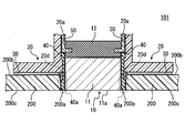
- FIG. 1 is a partial cross-sectional view illustrating a schematic configuration of an ultrasonic sensor device according to Embodiment 1 of the present disclosure.
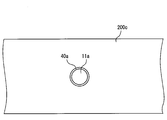
- FIG. 2 is a schematic diagram showing the outer shape of the bumper outer surface, the vibration surface of the ultrasonic transducer, and the protruding end portion of the outer peripheral surface vibration isolation member.
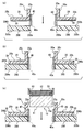
- FIGS. 3A to 3C are schematic diagrams for explaining a method of assembling the ultrasonic sensor device to the vehicle bumper.
- FIG. 4 is a partial cross-sectional view illustrating a schematic configuration of the ultrasonic sensor device according to the second embodiment of the present disclosure.
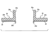
- FIG. 5 is a partial cross-sectional view for explaining a retainer protruding end of the retainer according to the second embodiment.
- FIG. 1 is a partial cross-sectional view illustrating a schematic configuration of an ultrasonic sensor device 100 according to the first embodiment.
- the ultrasonic sensor device 100 includes an ultrasonic sensor 10, a retainer 20, a double-sided tape 30, an outer peripheral surface vibration isolation member 40, and a case 50.
- the ultrasonic sensor device 100 operates as the vehicle ultrasonic sensor device according to the present disclosure.
- the ultrasonic sensor 10 includes an ultrasonic transducer 11 that transmits ultrasonic waves and receives ultrasonic waves reflected by an obstacle and a back surface vibration isolation member 12.
- the ultrasonic transducer 11 is provided by a microphone.
- the ultrasonic sensor 10 is assembled to a predetermined part of the vehicle bumper 200 and used as, for example, a back sonar or a corner sonar.
- the ultrasonic sensor 10 may be configured using a known sensor.
- Vehicle bumper 200 has an outer surface 200c exposed to the outside and an inner surface 200b located on the opposite side of outer surface 200c.
- an extension line along a distance (bumper thickness) from the outer surface 200c of the bumper to the inner surface 200b at a predetermined portion of the bumper 200 to which the ultrasonic sensor 10 is attached is referred to as a reference axis. That is, if the outer surface 200c and the inner surface 200b of the bumper 200 are substantially parallel at a predetermined portion, the reference axis is orthogonal to the outer surface 200c and the inner surface 200b.
- the direction toward the outside with respect to the vehicle along the reference axis is referred to as an outside direction
- the direction toward the inside with respect to the vehicle is referred to as an inside direction (or back side direction).
- the direction from the inner surface 200b of the bumper toward the outer surface 200c is also the direction toward the end with respect to the vehicle, it is also referred to as the tip direction.
- the housing of the microphone 11 is formed of a member made conductive by forming a conductive film on the surface of a metal material or an insulating material.
- the housing of the microphone 11 is formed of aluminum, and the vibration surface 11a is circular.
- the back vibration isolating member 12 is a vibration isolating elastic body for reducing vibration generated in the microphone 11.
- the back vibration isolator 12 for example, rubber such as silicon rubber may be used.
- the back vibration isolating member 12 is bonded to the ultrasonic sensor 10 with, for example, a silicon-based adhesive so as to cover the surface of the microphone 11 opposite to the vibration surface 10a.
- the retainer 20 is attached to an inner surface 200b of a vehicle bumper 200 provided with a through hole (hereinafter referred to as a bumper hole) 200a formed along a reference axis, and holds the ultrasonic sensor 10 in a predetermined position with respect to the vehicle bumper 200. It is a member to do.
- the retainer 20 functions as a holding member.
- the retainer 20 is formed of a material having a lower elastic modulus than the outer peripheral surface vibration-proof member 40.
- the retainer 20 may be formed of a resin such as polybutylene terephthalate (PBT).
- the retainer 20 is roughly composed of a plate-like portion 20b that faces the inner surface 200b of the vehicle bumper 200 and a cylindrical portion 20c that protrudes inward along the reference axis from the plate-like portion 20b.
- a part of the ultrasonic sensor 10 is accommodated in a through hole (hereinafter, retainer hole 20a) provided in the cylindrical portion 20c along the reference axis.
- retainer hole 20a As shown in FIG. 1, in a state where the ultrasonic sensor 10 is attached to a predetermined part of the bumper 200 of the vehicle, a part (first part) is accommodated in the bumper hole 200 and the other part (second part) is a retainer. It is stored in the hole 20a.
- the retainer hole 20a functions as a holding member hole.
- the central axis of the retainer hole 20a is orthogonal to the inner surface (hereinafter referred to as the bumper inner surface) 200b of the vehicle bumper 200. Further, the fitting direction of the protruding end portion 40a of the outer peripheral surface vibration-proofing member 40, which will be described later, into the bumper hole 200a is substantially parallel to the reference axis. Moreover, the attachment direction which is a direction which attaches the retainer 20 to the bumper 200 has faced the outer side direction (front-end
- the double-sided tape 30 is a fixing member for fixing the retainer 20 to the vehicle bumper 200.
- the double-sided tape 30 may be configured to be bonded in advance to the surface of the plate-like portion 20b of the retainer 20 that faces the bumper inner surface 200b of the vehicle bumper 200 in advance.
- the retainer 20 may be fixed to the vehicle bumper 200 with an adhesive or the like, or the retainer 20 may be fixed to the vehicle bumper 200 by welding or spray bonding.
- the outer peripheral surface vibration-proof member 40 is a vibration-proof elastic body for reducing vibration generated in the ultrasonic vibrator 11 of the ultrasonic sensor 10.
- the outer peripheral surface vibration-proofing member 40 for example, rubber such as silicon rubber may be used.
- the same material as the back surface anti-vibration member 12 may be used, or a different material may be used.
- the outer peripheral surface vibration isolation member 40 is integrally formed with the retainer 20 (for example, insert molding or two-color molding) on the inner peripheral surface of the retainer hole 20a. More specifically, the outer peripheral surface vibration isolation member 40 is provided so as to cover the outer periphery (in other words, the side surface) in the radial direction of the retainer hole 20a in the microphone 11 when the ultrasonic sensor 10 is accommodated in the retainer hole 20a. .
- the outer peripheral surface vibration-proof member 40 suppresses vibrations on the side surface of the ultrasonic sensor 10.
- the conventional technology has integrated a vibration isolating member such as silicon rubber on the side surface of the ultrasonic sensor 10 by bonding or the like.
- the vibration isolating member is not integrated on the side surface of the ultrasonic sensor 10, and the outer peripheral surface vibration isolating member 40 is integrated on the retainer 20 side.
- the vibration isolating member may not be integrated over the entire side surface of the ultrasonic sensor 10, or the vibration isolating member may not be integrated with a part of the side surface of the ultrasonic sensor 10. That is, the vibration isolating member that covers the entire side surface of the ultrasonic sensor 10 or at least a part of the side surface is integrated with the retainer 20.
- the vibration isolating member is not integrated with a part of the side surface of the ultrasonic sensor 10
- the retainer is located in a region corresponding to the vibration isolating member. About the 20 side area
- the outer peripheral surface vibration-proof member 40 protrudes outward along the reference axis from the surface of the retainer 20 that contacts the vehicle bumper 200 so as to contact and fit the opening edge of the bumper hole 200a. Is provided. That is, it protrudes along the direction in which the retainer 20 is attached to the vehicle bumper 200.
- a surface that contacts the retainer 20 is referred to as a contact surface.
- the outer peripheral surface vibration isolation member 40 functions as a vibration isolation member.
- the hole shape and diameter of the retainer hole 20a and the hole shape and diameter of the bumper hole 200a are provided substantially the same, and the outer peripheral surface vibration isolation member 40 extends along the inner peripheral surface of the retainer hole 20a.
- the bumper extends from the contact surface of the bumper so as to protrude in the mounting direction.
- the portion of the outer peripheral surface vibration isolation member 40 that protrudes in the mounting direction from the bumper contact surface is hereinafter referred to as a protruding end portion 40a.
- the bumper contact surface described above is, in other words, the surface of the plate-like portion of the retainer 20 that faces the inner surface 200b of the vehicle bumper 200.
- the tip of the protruding end 40 a is the outer surface of the vehicle bumper 200.
- bumper outer surface 200c is provided so as to be substantially in the same plane.
- the retainer hole 20a has a predetermined length on the side opposite to the mounting direction of the retainer hole 20a. It is provided halfway.
- the present invention is not necessarily limited thereto.
- the case 50 is a housing to which the ultrasonic sensor 10 is assembled.
- the case 50 When roughly classified, the case 50 is roughly opened in a substantially box-shaped main body portion in which a circuit board (not shown) is accommodated and a bottom surface portion of the box body of the main body portion. It consists of an opening that protrudes in a cylindrical shape on the side and into which the ultrasonic sensor 10 is assembled. In FIG. 1, for convenience, only a part of the opening of the case 50 is illustrated.
- the ultrasonic sensor 10 is assembled to the case 50 by being lightly press-fitted into the opening of the case 50 with the back vibration-proof member 12 at the top.
- the case 50 has a structure that is fixed when the ultrasonic sensor 10 is inserted into the opening by a certain amount.
- the hole shape and the diameter of the outer periphery of the opening of the case 50 are provided in substantially the same shape and diameter as the retainer hole 20a.
- the outer peripheral surface vibration-proof member 40 provided partway through the retainer hole 20a and the opening of the case 50 that is fixed when a certain amount of the ultrasonic sensor 10 is inserted are provided so as to satisfy the following conditions. It has been. Specifically, when the tip of the opening of the case 50 with the ultrasonic sensor 10 assembled is inserted into the retainer hole 20a of the retainer 20 fitted to the bumper hole 200a with the protruding end 40a fitted into the bumper hole 200a.
- the vibration surface 11a of the microphone 11 that is, the vibration surface of the ultrasonic sensor 10) 11a is provided so as to be positioned substantially in the same plane as the bumper outer surface 200c.
- the ultrasonic sensor device 100 configured as described above is used by being fixed in a state where a part of the ultrasonic sensor 10 is disposed inside the bumper hole 200a so that sensing can be performed via the bumper hole 200a. . That is, the ultrasonic sensor device 100 can transmit and receive ultrasonic waves without using the vehicle bumper 200.
- the bumper outer surface 200c and the vibration surface 11a of the ultrasonic transducer 11 are located on substantially the same plane.
- the outer shape of the bumper outer surface 200c and the vibration surface 11a of the ultrasonic transducer 11 are in a concentric relationship as shown in FIG.
- the protruding end portion 40a of the outer peripheral surface vibration-proof member 40 is located on substantially the same plane, and the respective outer shapes are It is a concentric relationship.
- the retainer 20 is first attached to the vehicle bumper 200 provided with the bumper hole 200a.
- the front end of the protruding end portion 40a of the outer circumferential surface vibration-proof member 40 is inserted into the bumper hole 200a from the inner surface 200b of the vehicle bumper 200 in the outer direction (front end direction) along the reference axis (FIG. 3). (See (a)).
- the protruding end 40a of the outer peripheral surface vibration-proof member 40 is elastically deformed, the protruding end 40a can be press-fitted toward the outer surface 200c of the vehicle bumper 200 in a state where the protruding end 40a is in contact with the inner wall of the bumper hole 200a.
- the projecting end portion 40a is pushed into the bumper hole 200a in the outward direction (front end direction) along the reference axis. Then, the double-sided tape 30 adhered to the bumper contact surface is also adhered to the bumper inner surface 200b, and the retainer 20 is fixed to the vehicle bumper 200 (see FIG. 3B). The process so far corresponds to a holding member attaching process.
- the tip of the opening of the case 50 with the ultrasonic sensor 10 assembled is inserted into the retainer hole 20a of the retainer 20. That is, the ultrasonic sensor 10 is inserted into the retainer hole 20a of the retainer 20 in the outward direction (front end direction) along the reference axis with the vibration surface 11a at the head (see FIG. 3C).
- the tip of the opening of the case 50 is a retainer with the vehicle bumper outer surface 200c, the vibration surface 11a of the ultrasonic sensor 10 and the protruding end portion 40a of the outer peripheral surface vibration-proof member 40 positioned substantially in the same plane.
- the ultrasonic sensor 10 is held at a predetermined position by being hooked and fixed to the outer peripheral surface vibration isolation member 40 provided halfway through the hole 20a (see FIG. 1). That is, the ultrasonic sensor 10 is fixed to the vehicle bumper 200. This process corresponds to an ultrasonic sensor accommodation process.
- the retainer 20 is provided with the outer peripheral surface anti-vibration member 40 so as to fit into the bumper hole 200a. Therefore, the outer peripheral surface anti-vibration member 40 (specifically, the protruding end portion 40a) is attached to the retainer 20. By fitting the bumper hole 200a, the retainer 20 can be easily positioned with respect to the bumper hole 200a.
- the outer peripheral surface vibration isolation member 40 is provided so as to cover the outer periphery of the ultrasonic sensor 10 when the ultrasonic sensor 10 is accommodated in the retainer hole 20a, the outer peripheral surface vibration isolation member 40 is provided in the bumper hole 200a. If fitted, the center positions of the retainer hole 20a and the bumper hole 200a are aligned. Therefore, the ultrasonic sensor 10 can be easily inserted into the bumper hole 200a and fixed by accommodating the ultrasonic sensor 10 in the holding member hole in a state in which the outer peripheral surface vibration-proof member 40 is fitted in the bumper hole 200a. it can. That is, the ultrasonic sensor 10 can be inserted into the bumper hole 200a as it is, and positioning of the vehicle ultrasonic sensor device to the bumper 200 is facilitated.
- the outer peripheral surface vibration-proof member 40 is an elastic body and can be press-fitted into the bumper hole 200a unlike a rigid body, when the holding member is positioned relative to the bumper hole 200a using a new rigid body positioning structure. Necessary fitting clearance is not required. Moreover, the fitting clearance required when positioning the bumper hole 200a and the through hole of the holding member of the ultrasonic sensor 10 using a rigid jig such as a metal rod is also unnecessary. Therefore, it is possible to prevent positional displacement corresponding to the fitting clearance.
- the outer peripheral surface vibration isolation member 40 protrudes from the bumper contact surface that contacts the vehicle bumper of the retainer 20, the outer side of the vehicle bumper 200 is in a state where the ultrasonic sensor 10 is housed in the retainer 20 attached to the vehicle bumper. From this, only the outer surface vibration isolator 40 and the ultrasonic sensor 10 can be seen in the region of the bumper hole 200a. Since the outer peripheral vibration isolation member 40 is generally provided so as to cover the periphery of the ultrasonic sensor 10, the outer appearance when the ultrasonic sensor can be accurately positioned and inserted into the bumper hole 200a is as follows. Similarly, a good appearance can be obtained.
- the bumper outer surface 200c, the ultrasonic sensor 10 (specifically, the vibration surface 11a), and the outer peripheral surface vibration isolation member 40 (specifically, the protruding end portion 40a) are located on substantially the same plane.
- the vibration surface 11a the ultrasonic sensor 10
- the outer peripheral surface vibration isolation member 40 specifically, the protruding end portion 40a
- FIG. 4 is a partial cross-sectional view illustrating a schematic configuration of the ultrasonic sensor device 101 according to the second embodiment.
- members having the same functions as those shown in the drawings used in the description of the first embodiment are given the same reference numerals, and descriptions thereof are omitted.
- the ultrasonic sensor device 101 includes the ultrasonic sensor 10, the retainer 20, the double-sided tape 30, the outer peripheral surface vibration isolation member 40, and the case 50, as with the ultrasonic sensor device 100. Therefore, the ultrasonic sensor device 101 also operates as a vehicle ultrasonic sensor device.
- the ultrasonic sensor device 101 has the same configuration as that of the ultrasonic sensor device 100 according to the first embodiment, except that the retainer 20 and the outer peripheral surface vibration isolation member 40 are partially different in shape. Below, the shape of the retainer 20 and the outer peripheral surface vibration isolator 40 characteristic of the ultrasonic sensor device 101 will be described.
- the difference between the retainer 20 of the second embodiment and the retainer 20 of the first embodiment is that the retainer 20 is directed to the mounting direction of the retainer 20 rather than the bumper contact surface described above so as to contact and fit the opening edge of the bumper hole 200a. It has a protruding end portion (hereinafter referred to as a retainer protruding end) 20d that protrudes in a protruding manner (see FIG. 5).
- the retainer protrusion 20d functions as a holding member protrusion.
- the retainer 20 of the second embodiment is also located on the outer peripheral side with respect to the outer peripheral surface vibration isolation member 40.
- the retainer protruding end 20d of the second embodiment is provided with a smaller protrusion from the bumper contact surface than the protruding end portion 40a of the outer peripheral surface vibration isolation member 40, and the tip is covered with the outer peripheral surface vibration isolation member 40. Yes.
- the retainer 20 of the second embodiment has the configuration of the first embodiment in at least a part of the region of the outer peripheral surface vibration isolation member 40 of the first embodiment excluding the region from the tip of the protruding end 40a to a predetermined length. It protrudes more toward the center of the retainer hole 20a.
- the outer peripheral surface vibration isolation member 40 is compared with the region of the outer peripheral surface vibration isolation member 40 of the first embodiment by the amount that the retainer 20 protrudes to the center side of the retainer hole 20a from the configuration of the first embodiment. It is provided by shaving.
- the outer peripheral surface vibration-proof member 40 has a length in the radial direction of the scraped region and a length in the radial direction of the tip of the retainer protruding end 20d from the tip of the retainer protruding end 20d to the tip of the protruding end 40a. It will be provided for the length.
- the diameter of the inner peripheral surface of the cylindrical outer surface antivibration member 40 is the same as that of the first embodiment, and the outer periphery of the ultrasonic sensor 10 can be covered when the ultrasonic sensor 10 is stored in the retainer hole 20a. It is assumed that
- the outer peripheral surface vibration-proof member 40 (specifically, the protruding end portion 40a) can be fitted into the bumper hole 200a, and the retainer protruding end 20d of the retainer 20 can be fitted into the bumper hole 200a.
- the outer circumferential surface vibration isolating member 40 When only the outer circumferential surface vibration isolating member 40 is fitted into the bumper hole 200a, the outer circumferential surface vibration isolating member 40 is an elastic body. Therefore, when a force is applied in the bumper contact surface direction, the outer circumferential surface vibration isolating member. There is a possibility that 40 will be bent and disengaged.
- the retainer protruding end 20d is also fitted in the bumper hole 200a, the retainer 20 is made of a material having a lower elastic modulus than that of the outer peripheral surface vibration isolating member 40, so that a force is applied in the bumper contact surface direction. Even if it works, it is more difficult to bend and the fitting is difficult to come off.
- the tip of the retainer protrusion 20d is covered with the outer peripheral surface vibration isolation member 40. Therefore, in the appearance of the vehicle bumper 200, the bumper outer surface 200c and the ultrasonic sensor 10 (specifically, the vibration surface 11a). ) And the outer peripheral surface vibration-proof member 40 (specifically, the protruding end portion 40a) are positioned on substantially the same plane. Therefore, it is possible to obtain a good appearance even with the configuration of the second embodiment.
- the present invention is not necessarily limited thereto.
- the idea of the present disclosure can be applied to other shapes such as a rectangular shape.
- the shape of the retainer hole 20a or the bumper hole 200a is a shape other than a circle
- the retainer 20 is perpendicular to the attaching direction of the retainer 20 when the ultrasonic sensor 10 is accommodated in the retainer hole 20a. What is necessary is just to set it as the structure which provides the outer peripheral surface anti-vibration member 40 so that the outer periphery of the said ultrasonic sensor 10 of the crossing direction may be covered.
Abstract
A vehicle ultrasonic sensor apparatus is provided with an ultrasonic sensor including an ultrasonic vibrator, and a holder member for housing the ultrasonic sensor. The ultrasonic sensor is mounted at a predetermined location of a vehicle bumper having an outer surface exposed to the outside and an inner surface positioned on the opposite side to the outer surface. At the predetermined location of the bumper, a bumper hole is provided in a front end direction from the inner surface toward the outer surface. The holder member has a holder member hole in the front end direction. A first portion of the ultrasonic sensor is housed in the bumper hole, while a second portion is housed in the holder member hole. The inner surface of the bumper includes a contact surface in contact with the holder member. The holder member is made of an elastic material and is integrated with an antivibration member which covers at least a part of a side surface of the ultrasonic sensor, with the second portion of the ultrasonic sensor housed in the holder member hole. The antivibration member includes a protruding end portion protruding beyond the contact surface of the bumper in the front end direction in such a manner as to be fitted in the bumper hole.
Description
本開示は、2012年4月24日に出願された日本出願番号2012-099052号に基づくもので、ここにその記載内容を援用する。
This disclosure is based on Japanese Patent Application No. 2012-099052 filed on April 24, 2012, the contents of which are incorporated herein by reference.
本開示は、車両用超音波センサ装置及び車両用超音波センサ装置の組み付け方法に関するものである。
The present disclosure relates to a vehicle ultrasonic sensor device and a method for assembling the vehicle ultrasonic sensor device.
従来、貫通孔の形成された車両バンパに対し、貫通孔を介してセンサ素子がセンシング可能となるように組み付けられる超音波センサ装置が知られている。
Conventionally, there has been known an ultrasonic sensor device that is assembled to a vehicle bumper having a through hole so that a sensor element can be sensed through the through hole.
例えば、特許文献1には、貫通孔の形成された部分の車両バンパの内側に、管部を有する保持部材を接着等で取り付けた後、この保持部材の管部に超音波センサのモジュールを挿入することで、車両バンパに超音波センサのモジュールを組み付ける技術が開示されている。このようすると、保持部材を取り付けても車両パンパの外面意匠に変化がないことから、意匠性が低下しない。
For example, in Patent Document 1, a holding member having a pipe part is attached to the inside of a vehicle bumper where a through hole is formed by bonding or the like, and then an ultrasonic sensor module is inserted into the pipe part of the holding member. Thus, a technique for assembling an ultrasonic sensor module to a vehicle bumper is disclosed. If it does in this way, even if a holding member is attached, since the external design of a vehicle bumper does not change, design nature does not fall.
さらに、特許文献1には、超音波センサのモジュールの頭部が車両バンパの外面とほぼ同一平面に位置するようになるまで、超音波センサを車両バンパの貫通孔に差し込むことで、良好な外観が得られるようにすることも開示されている。
Furthermore, Patent Document 1 discloses that the ultrasonic sensor is inserted into the through-hole of the vehicle bumper until the head of the module of the ultrasonic sensor is positioned substantially flush with the outer surface of the vehicle bumper. Is also disclosed.
また、一般的には、超音波が送波される方向を限定するために、超音波センサに備えられている超音波振動子の複数の面のうち、センシングしようとする方向の面以外の面を、振動を抑制する防振部材で覆うことが知られている。
In general, in order to limit the direction in which the ultrasonic wave is transmitted, a surface other than the surface in the direction to be sensed among a plurality of surfaces of the ultrasonic transducer provided in the ultrasonic sensor. Is known to be covered with a vibration isolating member that suppresses vibration.
しかしながら、特許文献1に開示の技術では、保持部材を接着等でバンパに固定する際、貫通孔の形成された部分の車両バンパを外側から眺めつつ、内側から保持部材を接着等で固定するため、車両バンパの貫通孔の中心と、保持部材の管部の軸とを一致させにくかった。また、貫通孔の中心と保持部材の管部の軸心とがずれるほど保持部材に超音波センサのモジュールを挿入しても、車両バンパの貫通孔には差し込むことができない不具合が生じやすくなる。
However, in the technique disclosed in Patent Document 1, when the holding member is fixed to the bumper by bonding or the like, the holding member is fixed by bonding or the like while looking at the vehicle bumper of the portion where the through hole is formed from the outside. The center of the through hole of the vehicle bumper and the axis of the tube portion of the holding member are difficult to match. In addition, even if the ultrasonic sensor module is inserted into the holding member so that the center of the through hole is displaced from the axis of the tube portion of the holding member, a problem that it cannot be inserted into the through hole of the vehicle bumper is likely to occur.
良好な外観が得られるようにするためには、超音波センサを貫通孔に差し込んだ際の貫通孔の径方向の隙間を小さくする必要がある。また、超音波センサを防振部材で覆う場合には、防振部材を貫通孔に差し込んだ後に生じる貫通孔の隙間を小さくする必要がある。しかしながら、この隙間が小さくなるほど、車両バンパの貫通孔の中心と、保持部材の管部の軸との位置ずれの許容値が小さくなるため、車両バンパへの超音波センサのモジュールの組み付けは、より困難になる。
In order to obtain a good appearance, it is necessary to reduce the radial gap of the through hole when the ultrasonic sensor is inserted into the through hole. Further, when the ultrasonic sensor is covered with the vibration isolating member, it is necessary to reduce the gap between the through holes generated after the vibration isolating member is inserted into the through hole. However, the smaller the gap is, the smaller the allowable value of positional deviation between the center of the through hole of the vehicle bumper and the axis of the tube portion of the holding member is. Therefore, the assembly of the ultrasonic sensor module to the vehicle bumper is more It becomes difficult.
本開示は、上記点に鑑みてなされたものであり、その目的は、車両バンパに設けられた貫通孔に超音波センサを差し込んで車両バンパへの組み付けを行う場合において、良好な外観が得られるようにしながらも、組み付けを容易にする車両用超音波センサ装置及び車両用超音波センサ装置の組み付け方法を提供することにある。
The present disclosure has been made in view of the above points, and an object of the present disclosure is to obtain a good appearance when an ultrasonic sensor is inserted into a through-hole provided in a vehicle bumper and is assembled to the vehicle bumper. It is another object of the present invention to provide an ultrasonic sensor device for a vehicle and an assembling method of the ultrasonic sensor device for a vehicle that facilitate the assembly.
本開示の第一態様による車両用超音波センサ装置は、超音波振動子を備えた超音波センサと、前記超音波センサを収容する保持部材とを備える。前記超音波センサは、車両のバンパの所定部位に取り付けられ、前記バンパは、外側に露出される外面と前記外面の反対側に位置する内面を有する。前記バンパの所定部位には、前記内面から前記外面に向かう方向である先端方向に前記バンパを貫通するバンパ孔が設けられている。前記超音波センサの第1部分は、前記バンパ孔に収容されている。前記バンパの内面は、前記保持部材の前記バンパの内面に正対する面と接する接面を有する。前記保持部材には、前記先端方向に前記保持部材を貫通する保持部材孔が設けられている。前記超音波センサの第2部分は、前記保持部材孔に収容されている。前記保持部材は、弾性材料からなり、前記保持部材孔に前記超音波センサの第2部分が収容された状態で当該超音波センサの側面の少なくとも一部を覆う防振部材と一体化している。前記防振部材は、前記先端方向に突出する突出端部を有する。前記突出端部は、前記バンパ孔に嵌合するように、前記バンパの接面よりも前記先端方向に突出している。
The vehicle ultrasonic sensor device according to the first aspect of the present disclosure includes an ultrasonic sensor including an ultrasonic transducer, and a holding member that houses the ultrasonic sensor. The ultrasonic sensor is attached to a predetermined part of a bumper of a vehicle, and the bumper has an outer surface exposed to the outside and an inner surface located on the opposite side of the outer surface. A predetermined portion of the bumper is provided with a bumper hole penetrating the bumper in a tip direction that is a direction from the inner surface toward the outer surface. The first portion of the ultrasonic sensor is accommodated in the bumper hole. The inner surface of the bumper has a contact surface that contacts a surface of the holding member that faces the inner surface of the bumper. The holding member is provided with a holding member hole penetrating the holding member in the distal direction. The second portion of the ultrasonic sensor is accommodated in the holding member hole. The holding member is made of an elastic material, and is integrated with a vibration isolating member that covers at least a part of a side surface of the ultrasonic sensor in a state where the second portion of the ultrasonic sensor is accommodated in the holding member hole. The vibration isolating member has a protruding end protruding in the tip direction. The protruding end portion protrudes in the tip direction from the contact surface of the bumper so as to fit into the bumper hole.
上記車両用超音波センサ装置によると、車両バンパに設けられた貫通孔に超音波センサを差し込んで車両バンパへの組み付けを行う場合において、良好な外観が得られるようにしながらも、組み付けも容易になる。
According to the above-described ultrasonic sensor device for a vehicle, when an ultrasonic sensor is inserted into a through-hole provided in the vehicle bumper and is assembled to the vehicle bumper, the good appearance can be obtained and the assembly is also easy. Become.
本開示他の態様による貫通孔が設けられた前記車両のバンパの内面に前記第一態様による車両用超音波センサ装置を組み付ける方法は、前記保持部材と一体化されている前記防振部材の突出端部が、前記バンパ孔に嵌合し、前記バンパの内面に前記保持部材の前記バンパの内面に正対する面が接するように前記保持部材を取り付けることと前記超音波センサの振動面が前記バンパの外面と略同一平面に位置するまで前記超音波センサを前記保持部材孔に収容することを含む。
According to another aspect of the present disclosure, a method of assembling the vehicle ultrasonic sensor device according to the first aspect on an inner surface of a bumper of the vehicle provided with a through-hole includes a protrusion of the vibration isolation member integrated with the holding member. The holding member is attached so that the end portion is fitted into the bumper hole, and the surface of the holding member facing the inner surface of the bumper is in contact with the inner surface of the bumper, and the vibration surface of the ultrasonic sensor is the bumper. The ultrasonic sensor is housed in the holding member hole until it is positioned substantially in the same plane as the outer surface of the holding member.
上記車両用超音波センサ装置の組み付け方法によると、車両バンパに設けられた貫通孔に超音波センサを差し込んで車両バンパへの組み付けを行う場合において、良好な外観が得られるようにしながらも、組み付けも容易になる。
According to the method for assembling the vehicle ultrasonic sensor device described above, when an ultrasonic sensor is inserted into a through-hole provided in the vehicle bumper to be assembled to the vehicle bumper, the assembly is performed while obtaining a good appearance. Will also be easier.
本開示についての上記目的およびその他の目的、特徴や利点は、添付の図面を参照しながら下記の詳細な記述により、より明確になる。その図面は、
図1は、本開示の実施形態1による超音波センサ装置の概略構成を示す部分断面図であり、
図2は、バンパ外面と、超音波振動子の振動面と、外周面防振部材の突出端部との外形形状を示す模式図であり、
図3(a)から図3(c)は、車両バンパに対する超音波センサ装置の組み付け方法を説明するための模式図であり、
図4は、本開示の実施形態2による超音波センサ装置の概略構成を示す部分断面図であり、
図5は、実施形態2のリテーナのリテーナ突端を説明するための部分断面図である。
The above and other objects, features and advantages of the present disclosure will become more apparent from the following detailed description with reference to the accompanying drawings. The drawing
FIG. 1 is a partial cross-sectional view illustrating a schematic configuration of an ultrasonic sensor device according to Embodiment 1 of the present disclosure. FIG. 2 is a schematic diagram showing the outer shape of the bumper outer surface, the vibration surface of the ultrasonic transducer, and the protruding end portion of the outer peripheral surface vibration isolation member. FIGS. 3A to 3C are schematic diagrams for explaining a method of assembling the ultrasonic sensor device to the vehicle bumper. FIG. 4 is a partial cross-sectional view illustrating a schematic configuration of the ultrasonic sensor device according to the second embodiment of the present disclosure. FIG. 5 is a partial cross-sectional view for explaining a retainer protruding end of the retainer according to the second embodiment.
以下、本開示の実施形態について図面を用いて説明する。
Hereinafter, embodiments of the present disclosure will be described with reference to the drawings.
(実施形態1)
図1は、実施形態1の超音波センサ装置100の概略構成を示す部分断面図である。図1に示すように、超音波センサ装置100は、超音波センサ10、リテーナ20、両面テープ30、外周面防振部材40、及びケース50を含む。超音波センサ装置100が本開示による車両用超音波センサ装置として動作する。 (Embodiment 1)
FIG. 1 is a partial cross-sectional view illustrating a schematic configuration of anultrasonic sensor device 100 according to the first embodiment. As shown in FIG. 1, the ultrasonic sensor device 100 includes an ultrasonic sensor 10, a retainer 20, a double-sided tape 30, an outer peripheral surface vibration isolation member 40, and a case 50. The ultrasonic sensor device 100 operates as the vehicle ultrasonic sensor device according to the present disclosure.
図1は、実施形態1の超音波センサ装置100の概略構成を示す部分断面図である。図1に示すように、超音波センサ装置100は、超音波センサ10、リテーナ20、両面テープ30、外周面防振部材40、及びケース50を含む。超音波センサ装置100が本開示による車両用超音波センサ装置として動作する。 (Embodiment 1)
FIG. 1 is a partial cross-sectional view illustrating a schematic configuration of an
超音波センサ10は、超音波を送波し、障害物にて反射された超音波を受信する超音波振動子11や裏面防振部材12を備える。本実施形態で、超音波振動子11は、マイクロホンにより提供されている。超音波センサ10は、車両バンパ200の所定部位に組み付けられて、例えばバックソナー又はコーナーソナーとして用いられる。超音波センサ10としては、公知のものを用いる構成とすればよい。車両バンパ200は、外側に露出される外面200cと外面200cの反対側に位置する内面200bを有する。以下、超音波センサ10が取り付けられたバンパ200の所定部位において、バンパの外面200cから内面200bまでの距離(バンパの厚さ)に沿う延長線を参考軸と称する。即ち、所定部位において、バンパ200の外面200cと内面200bが略平行であれば、参考軸は、外面200cと内面200bに直交する。以下、参考軸に沿って、車両に対して外側に向かう方向を外側方向と称し、車両に対して内側に向かう方向を内側方向(もしくは、裏側方向)と称する。さらに、バンパの内面200bから外面200cに向かう方向は、車両に対して端部を向かう方向でもあることから、先端方向とも称する。
The ultrasonic sensor 10 includes an ultrasonic transducer 11 that transmits ultrasonic waves and receives ultrasonic waves reflected by an obstacle and a back surface vibration isolation member 12. In the present embodiment, the ultrasonic transducer 11 is provided by a microphone. The ultrasonic sensor 10 is assembled to a predetermined part of the vehicle bumper 200 and used as, for example, a back sonar or a corner sonar. The ultrasonic sensor 10 may be configured using a known sensor. Vehicle bumper 200 has an outer surface 200c exposed to the outside and an inner surface 200b located on the opposite side of outer surface 200c. Hereinafter, an extension line along a distance (bumper thickness) from the outer surface 200c of the bumper to the inner surface 200b at a predetermined portion of the bumper 200 to which the ultrasonic sensor 10 is attached is referred to as a reference axis. That is, if the outer surface 200c and the inner surface 200b of the bumper 200 are substantially parallel at a predetermined portion, the reference axis is orthogonal to the outer surface 200c and the inner surface 200b. Hereinafter, the direction toward the outside with respect to the vehicle along the reference axis is referred to as an outside direction, and the direction toward the inside with respect to the vehicle is referred to as an inside direction (or back side direction). Furthermore, since the direction from the inner surface 200b of the bumper toward the outer surface 200c is also the direction toward the end with respect to the vehicle, it is also referred to as the tip direction.
例えばマイクロホン11のハウジングは、金属材料や絶縁材料の表面に導電膜を形成して導電性を持たせた部材で形成されるものとする。本実施形態では、一例としてマイクロホン11のハウジングはアルミニウムで形成されるものとし、振動面11aが円形状になっているものとする。
For example, it is assumed that the housing of the microphone 11 is formed of a member made conductive by forming a conductive film on the surface of a metal material or an insulating material. In the present embodiment, as an example, it is assumed that the housing of the microphone 11 is formed of aluminum, and the vibration surface 11a is circular.
裏面防振部材12は、マイクロホン11に生じる振動を軽減するための防振性の弾性体である。裏面防振部材12としては、例えばシリコンゴム等のゴムを用いる構成とすればよい。裏面防振部材12は、マイクロホン11の振動面10aと反対側の面を覆うように、例えばシリコン系の接着剤等により超音波センサ10に接着されている。
The back vibration isolating member 12 is a vibration isolating elastic body for reducing vibration generated in the microphone 11. As the back vibration isolator 12, for example, rubber such as silicon rubber may be used. The back vibration isolating member 12 is bonded to the ultrasonic sensor 10 with, for example, a silicon-based adhesive so as to cover the surface of the microphone 11 opposite to the vibration surface 10a.
リテーナ20は、参考軸に沿って形成された貫通孔(以下、バンパ孔)200aの設けられた車両バンパ200の内面200bに取り付けられ、車両バンパ200に対して超音波センサ10を所定位置に保持する部材である。リテーナ20は、保持部材として機能する。リテーナ20は、外周面防振部材40よりも弾性率の低い材質で形成される。例えば、リテーナ20は、ポリブチレンテレフタレート(PBT)等の樹脂で形成する構成とすればよい。
The retainer 20 is attached to an inner surface 200b of a vehicle bumper 200 provided with a through hole (hereinafter referred to as a bumper hole) 200a formed along a reference axis, and holds the ultrasonic sensor 10 in a predetermined position with respect to the vehicle bumper 200. It is a member to do. The retainer 20 functions as a holding member. The retainer 20 is formed of a material having a lower elastic modulus than the outer peripheral surface vibration-proof member 40. For example, the retainer 20 may be formed of a resin such as polybutylene terephthalate (PBT).
リテーナ20は、大別すると、車両バンパ200の内面200bに正対する板状部20bと、その板状部20bから参考軸に沿って内側方向に突出した円筒状部20cとからなっている。また、上記円筒状部20cに前記参考軸に沿って設けられた貫通孔(以下、リテーナ孔20a)には、超音波センサ10の一部が収納されるようになっている。図1に示すように、超音波センサ10が車両のバンパ200の所定部位に取り付けられた状態で、一部(第1部分)はバンパ孔200に収納され、その他部位(第2部分)はリテーナ孔20aに収納されている。リテーナ孔20aが保持部材孔として機能する。
The retainer 20 is roughly composed of a plate-like portion 20b that faces the inner surface 200b of the vehicle bumper 200 and a cylindrical portion 20c that protrudes inward along the reference axis from the plate-like portion 20b. A part of the ultrasonic sensor 10 is accommodated in a through hole (hereinafter, retainer hole 20a) provided in the cylindrical portion 20c along the reference axis. As shown in FIG. 1, in a state where the ultrasonic sensor 10 is attached to a predetermined part of the bumper 200 of the vehicle, a part (first part) is accommodated in the bumper hole 200 and the other part (second part) is a retainer. It is stored in the hole 20a. The retainer hole 20a functions as a holding member hole.
リテーナ孔20aの中心軸は、車両バンパ200の内面(以下、バンパ内面と称する)200bと直交する。また、後述する外周面防振部材40の突出端部40aのバンパ孔200aへの嵌合方向は、参考軸と略平行している。また、リテーナ20をバンパ200に取り付ける方向である取り付け方向は、参考軸に沿って外側方向(先端方向)を向いている。
The central axis of the retainer hole 20a is orthogonal to the inner surface (hereinafter referred to as the bumper inner surface) 200b of the vehicle bumper 200. Further, the fitting direction of the protruding end portion 40a of the outer peripheral surface vibration-proofing member 40, which will be described later, into the bumper hole 200a is substantially parallel to the reference axis. Moreover, the attachment direction which is a direction which attaches the retainer 20 to the bumper 200 has faced the outer side direction (front-end | tip direction) along the reference axis.
両面テープ30は、リテーナ20を車両バンパ200に固定するための固定部材である。例えば両面テープ30は、リテーナ20の前述した板状部20bの、車両バンパ200のバンパ内面200bに正対する面に予め接着されている構成とすればよい。
The double-sided tape 30 is a fixing member for fixing the retainer 20 to the vehicle bumper 200. For example, the double-sided tape 30 may be configured to be bonded in advance to the surface of the plate-like portion 20b of the retainer 20 that faces the bumper inner surface 200b of the vehicle bumper 200 in advance.
なお、本実施形態では、両面テープ30を用いてリテーナ20を車両バンパ200に固定する構成を示すが、必ずしもこれに限らない。例えば、両面テープ以外にも、接着剤等でリテーナ20を車両バンパ200に固定する構成としてもよいし、溶接や吹き付け結合によってリテーナ20を車両バンパ200に固定する構成としてもよい。
In addition, in this embodiment, although the structure which fixes the retainer 20 to the vehicle bumper 200 using the double-sided tape 30 is shown, it does not necessarily restrict to this. For example, in addition to the double-sided tape, the retainer 20 may be fixed to the vehicle bumper 200 with an adhesive or the like, or the retainer 20 may be fixed to the vehicle bumper 200 by welding or spray bonding.
外周面防振部材40は、超音波センサ10の超音波振動子11に生じる振動を軽減するための防振性の弾性体である。外周面防振部材40としては、例えばシリコンゴム等のゴムを用いる構成とすればよい。なお、外周面防振部材40としては、裏面防振部材12と同一の材質を用いる構成としてもよいし、異なる材質を用いる構成としてもよい。
The outer peripheral surface vibration-proof member 40 is a vibration-proof elastic body for reducing vibration generated in the ultrasonic vibrator 11 of the ultrasonic sensor 10. As the outer peripheral surface vibration-proofing member 40, for example, rubber such as silicon rubber may be used. In addition, as the outer peripheral surface anti-vibration member 40, the same material as the back surface anti-vibration member 12 may be used, or a different material may be used.
外周面防振部材40は、リテーナ孔20aの内周面に、例えばリテーナ20と一体成形(例えばインサート成形や2色成形など)されている。より詳しくは、外周面防振部材40は、超音波センサ10をリテーナ孔20aに収納した際に、マイクロホン11におけるリテーナ孔20aの径方向の外周(言い換えると側面)を覆うように設けられている。
The outer peripheral surface vibration isolation member 40 is integrally formed with the retainer 20 (for example, insert molding or two-color molding) on the inner peripheral surface of the retainer hole 20a. More specifically, the outer peripheral surface vibration isolation member 40 is provided so as to cover the outer periphery (in other words, the side surface) in the radial direction of the retainer hole 20a in the microphone 11 when the ultrasonic sensor 10 is accommodated in the retainer hole 20a. .
これにより、外周面防振部材40は、超音波センサ10をリテーナ孔20aに収納した際に、超音波センサ10の側面の振動を抑制することになる。また、超音波外センサ10の側面の振動を抑制する目的として、従来までの技術では、超音波センサ10の側面に接着等でシリコンゴム等の防振部材を一体化していたが、本願では、超音波センサ10の側面に防振部材は一体化されず、リテーナ20側に外周面防振部材40を一体化している。
Thereby, when the ultrasonic sensor 10 is housed in the retainer hole 20a, the outer peripheral surface vibration-proof member 40 suppresses vibrations on the side surface of the ultrasonic sensor 10. In addition, for the purpose of suppressing vibration of the side surface of the ultrasonic sensor 10, the conventional technology has integrated a vibration isolating member such as silicon rubber on the side surface of the ultrasonic sensor 10 by bonding or the like. The vibration isolating member is not integrated on the side surface of the ultrasonic sensor 10, and the outer peripheral surface vibration isolating member 40 is integrated on the retainer 20 side.
なお、超音波センサ10の側面の全面にわたって防振部材が一体化されない構成としてもよいし、超音波センサ10の側面の一部に防振部材が一体化されない構成としてもよい。即ち、超音波センサ10の側面の全面または側面の少なくとも一部を覆う防振部材がリテーナ20と一体化される構成である。超音波センサ10の側面の一部に防振部材が一体化されない構成とする場合には、超音波センサ10をリテーナ孔20aに収納した際に、その防振部材に対応する領域に位置するリテーナ20側の領域については、外周面防振部材40を設けない構成としてもよい。
It should be noted that the vibration isolating member may not be integrated over the entire side surface of the ultrasonic sensor 10, or the vibration isolating member may not be integrated with a part of the side surface of the ultrasonic sensor 10. That is, the vibration isolating member that covers the entire side surface of the ultrasonic sensor 10 or at least a part of the side surface is integrated with the retainer 20. In the case where the vibration isolating member is not integrated with a part of the side surface of the ultrasonic sensor 10, when the ultrasonic sensor 10 is housed in the retainer hole 20a, the retainer is located in a region corresponding to the vibration isolating member. About the 20 side area | region, it is good also as a structure which does not provide the outer peripheral surface vibration isolator 40. FIG.
また、外周面防振部材40は、バンパ孔200aの開口縁部に当接して嵌合するように、リテーナ20の車両バンパ200に接する面よりも、参考軸に沿って外側方向に向けて突出して設けられている。即ち、リテーナ20の車両バンパ200への取り付け方向に沿って、突出している。以下、バンパ200の内面200bのうち、リテーナ20と当接する面を接面と称する。外周面防振部材40が防振部材として機能する。
Further, the outer peripheral surface vibration-proof member 40 protrudes outward along the reference axis from the surface of the retainer 20 that contacts the vehicle bumper 200 so as to contact and fit the opening edge of the bumper hole 200a. Is provided. That is, it protrudes along the direction in which the retainer 20 is attached to the vehicle bumper 200. Hereinafter, of the inner surface 200b of the bumper 200, a surface that contacts the retainer 20 is referred to as a contact surface. The outer peripheral surface vibration isolation member 40 functions as a vibration isolation member.
一例としては、リテーナ孔20aの孔形状及び径と、バンパ孔200aの孔形状及び径とが略同一に設けられており、外周面防振部材40は、リテーナ孔20aの内周面に沿って、バンパ接面よりも前記取り付け方向に突出するように延長して設けられている。
As an example, the hole shape and diameter of the retainer hole 20a and the hole shape and diameter of the bumper hole 200a are provided substantially the same, and the outer peripheral surface vibration isolation member 40 extends along the inner peripheral surface of the retainer hole 20a. The bumper extends from the contact surface of the bumper so as to protrude in the mounting direction.
外周面防振部材40のうちの、バンパ接面よりも前記取り付け方向に突出した部分を以降では、突出端部40aと呼ぶ。なお、前述のバンパ接面は、言い換えると、リテーナ20の前述した板状の部分の、車両バンパ200の内面200bに正対する面である。
The portion of the outer peripheral surface vibration isolation member 40 that protrudes in the mounting direction from the bumper contact surface is hereinafter referred to as a protruding end portion 40a. The bumper contact surface described above is, in other words, the surface of the plate-like portion of the retainer 20 that faces the inner surface 200b of the vehicle bumper 200.
さらに詳しくは、外周面防振部材40は、突出端部40aをバンパ孔200aに嵌合して、リテーナ20を車両バンパ200に取り付けた際に、突出端部40aの先端が車両バンパ200の外面(以下、バンパ外面)200cと略同一平面に位置するように設けられている。
More specifically, in the outer peripheral surface vibration-proof member 40, when the protruding end 40 a is fitted into the bumper hole 200 a and the retainer 20 is attached to the vehicle bumper 200, the tip of the protruding end 40 a is the outer surface of the vehicle bumper 200. (Hereinafter referred to as “bumper outer surface”) 200c is provided so as to be substantially in the same plane.
また、外周面防振部材40のうちの、リテーナ孔20aに収まっている部分については、リテーナ孔20aの前記取り付け方向とは反対方向側に所定長の空き領域が生じるように、リテーナ孔20aの途中まで設けられている。
In addition, with respect to the portion of the outer peripheral surface vibration isolating member 40 that is accommodated in the retainer hole 20a, the retainer hole 20a has a predetermined length on the side opposite to the mounting direction of the retainer hole 20a. It is provided halfway.
本実施形態では、リテーナ20と外周面防振部材40とを一体成形する構成を示したが、必ずしもこれに限らない。例えば、リテーナ20の成形後に、外周面防振部材40をリテーナ20に接着剤等で取り付ける構成(以下、変形例1)としてもよい。
In the present embodiment, the configuration in which the retainer 20 and the outer circumferential vibration isolating member 40 are integrally formed is shown, but the present invention is not necessarily limited thereto. For example, it is good also as a structure (henceforth the modification 1) which attaches the outer peripheral surface vibration isolator 40 to the retainer 20 with an adhesive etc. after shaping | molding of the retainer 20. FIG.
ケース50は、超音波センサ10が組みつけられる筐体であって、大別すると、図示しない回路基板が収容される略箱状の本体部と、その本体部の箱体の底面部から反開口側に円筒状で突出して超音波センサ10が組み付けられる開口部とからなる。図1では、便宜上、ケース50の開口部の一部のみを図示している。
The case 50 is a housing to which the ultrasonic sensor 10 is assembled. When roughly classified, the case 50 is roughly opened in a substantially box-shaped main body portion in which a circuit board (not shown) is accommodated and a bottom surface portion of the box body of the main body portion. It consists of an opening that protrudes in a cylindrical shape on the side and into which the ultrasonic sensor 10 is assembled. In FIG. 1, for convenience, only a part of the opening of the case 50 is illustrated.
超音波センサ10は、裏面防振部材12を先頭にしてケース50の開口部に軽圧入されることで、ケース50に組み付けられる。また、ケース50は、超音波センサ10が開口部に一定量挿入されたところで固定される構造になっている。
The ultrasonic sensor 10 is assembled to the case 50 by being lightly press-fitted into the opening of the case 50 with the back vibration-proof member 12 at the top. The case 50 has a structure that is fixed when the ultrasonic sensor 10 is inserted into the opening by a certain amount.
例えば、ケース50と裏面防振部材12とに、超音波センサ10がケース50の開口部に一定量挿入されたときに嵌合して固定されるように凹部や凸部が設けられている構成としてもよい。他にも、ケース50の開口部が一定の深さに設けられていることによって、超音波センサ10を開口部に一定量挿入したところで固定される構成としてもよい。
For example, a configuration in which a concave portion or a convex portion is provided on the case 50 and the back vibration isolating member 12 so that the ultrasonic sensor 10 is fitted and fixed when a certain amount of the ultrasonic sensor 10 is inserted into the opening portion of the case 50. It is good. In addition, since the opening of the case 50 is provided at a certain depth, the ultrasonic sensor 10 may be fixed when a certain amount is inserted into the opening.
一例として、ケース50の開口部の外周の孔形状及び径は、リテーナ孔20aと略同一形状及び径に設けられている。そして、超音波センサ10を組み付けたケース50の開口部をリテーナ孔20aに差し込んでいった場合に、ケース50の開口部の先端が、リテーナ孔20aの途中まで設けられた外周面防振部材40に引っ掛かって固定されるようになっている。
As an example, the hole shape and the diameter of the outer periphery of the opening of the case 50 are provided in substantially the same shape and diameter as the retainer hole 20a. When the opening portion of the case 50 with the ultrasonic sensor 10 assembled is inserted into the retainer hole 20a, the outer peripheral surface vibration-proof member 40 in which the tip of the opening portion of the case 50 is provided partway through the retainer hole 20a. It is designed to be hooked and fixed.
また、リテーナ孔20aの途中まで設けられた外周面防振部材40、及び超音波センサ10が一定量挿入されたところで固定される構造のケース50の開口部は、以下の条件を満たすように設けられている。具体的には、突出端部40aをバンパ孔200aに嵌合して車両バンパ200に取り付けたリテーナ20のリテーナ孔20aに、超音波センサ10を組み付けたケース50の開口部の先端を差し込んだ場合に、マイクロホン11の振動面(つまり、超音波センサ10の振動面)11aがバンパ外面200cと略同一平面に位置して固定されるように設けられている。
Moreover, the outer peripheral surface vibration-proof member 40 provided partway through the retainer hole 20a and the opening of the case 50 that is fixed when a certain amount of the ultrasonic sensor 10 is inserted are provided so as to satisfy the following conditions. It has been. Specifically, when the tip of the opening of the case 50 with the ultrasonic sensor 10 assembled is inserted into the retainer hole 20a of the retainer 20 fitted to the bumper hole 200a with the protruding end 40a fitted into the bumper hole 200a. In addition, the vibration surface 11a of the microphone 11 (that is, the vibration surface of the ultrasonic sensor 10) 11a is provided so as to be positioned substantially in the same plane as the bumper outer surface 200c.
このように構成される超音波センサ装置100は、バンパ孔200aを介してセンシングが可能なように、超音波センサ10の一部がバンパ孔200aの内部に配置された状態で固定して用いられる。即ち、超音波センサ装置100は、車両バンパ200を介さずに超音波の送波及び受波が可能である。そして、この固定状態で、前述したように、バンパ外面200cと超音波振動子11の振動面11aとが略同一平面に位置している。
The ultrasonic sensor device 100 configured as described above is used by being fixed in a state where a part of the ultrasonic sensor 10 is disposed inside the bumper hole 200a so that sensing can be performed via the bumper hole 200a. . That is, the ultrasonic sensor device 100 can transmit and receive ultrasonic waves without using the vehicle bumper 200. In this fixed state, as described above, the bumper outer surface 200c and the vibration surface 11a of the ultrasonic transducer 11 are located on substantially the same plane.
また、バンパ外面200cと超音波振動子11の振動面11aの外形形状が図2に示すように同心円の関係になっている。なお、本実施形態においては、バンパ外面200cと超音波振動子11の振動面11aとだけでなく、外周面防振部材40の突出端部40aも略同一平面に位置し、それぞれの外形形状が同心円の関係になっている。
Further, the outer shape of the bumper outer surface 200c and the vibration surface 11a of the ultrasonic transducer 11 are in a concentric relationship as shown in FIG. In the present embodiment, not only the bumper outer surface 200c and the vibration surface 11a of the ultrasonic transducer 11, but also the protruding end portion 40a of the outer peripheral surface vibration-proof member 40 is located on substantially the same plane, and the respective outer shapes are It is a concentric relationship.
次に、車両バンパ200に対する超音波センサ装置100の組み付け方法について、図1及び図3(a)~図3(c)を用いて説明する。
Next, a method of assembling the ultrasonic sensor device 100 to the vehicle bumper 200 will be described with reference to FIGS. 1 and 3A to 3C.
まず、バンパ孔200aの設けられた車両バンパ200に対し、まずリテーナ20を取り付ける。具体的には、外周面防振部材40の突出端部40aの先端を先頭に、参考軸に沿って外側方向(先端方向)に車両バンパ200の内面200bからバンパ孔200aに挿入する(図3(a)参照)。この際、外周面防振部材40の突出端部40aが弾性変形するので、突出端部40aがバンパ孔200aの内壁に接触した状態で車両バンパ200の外面200cに向けて圧入することができる。
First, the retainer 20 is first attached to the vehicle bumper 200 provided with the bumper hole 200a. Specifically, the front end of the protruding end portion 40a of the outer circumferential surface vibration-proof member 40 is inserted into the bumper hole 200a from the inner surface 200b of the vehicle bumper 200 in the outer direction (front end direction) along the reference axis (FIG. 3). (See (a)). At this time, since the protruding end 40a of the outer peripheral surface vibration-proof member 40 is elastically deformed, the protruding end 40a can be press-fitted toward the outer surface 200c of the vehicle bumper 200 in a state where the protruding end 40a is in contact with the inner wall of the bumper hole 200a.
続いて、リテーナ20の前述のバンパ接面が車両バンパ200のバンパ内面200bに接するまで、突出端部40aを参考軸に沿って外側方向(先端方向)にバンパ孔200aに押し込む。すると、バンパ接面に接着されている両面テープ30が、バンパ内面200bにも接着し、リテーナ20が車両バンパ200に対して固定される(図3(b)参照)。ここまでの工程が保持部材取り付け工程に相当する。
Subsequently, until the aforementioned bumper contact surface of the retainer 20 contacts the bumper inner surface 200b of the vehicle bumper 200, the projecting end portion 40a is pushed into the bumper hole 200a in the outward direction (front end direction) along the reference axis. Then, the double-sided tape 30 adhered to the bumper contact surface is also adhered to the bumper inner surface 200b, and the retainer 20 is fixed to the vehicle bumper 200 (see FIG. 3B). The process so far corresponds to a holding member attaching process.
リテーナ20を車両バンパ200に固定した後、リテーナ20のリテーナ孔20aに、超音波センサ10を組み付けたケース50の開口部の先端を差し込む。つまり、リテーナ20のリテーナ孔20aに、振動面11aを先頭にして参考軸に沿って外側方向(先端方向)に超音波センサ10を差し込む(図3(c)参照)。
After fixing the retainer 20 to the vehicle bumper 200, the tip of the opening of the case 50 with the ultrasonic sensor 10 assembled is inserted into the retainer hole 20a of the retainer 20. That is, the ultrasonic sensor 10 is inserted into the retainer hole 20a of the retainer 20 in the outward direction (front end direction) along the reference axis with the vibration surface 11a at the head (see FIG. 3C).
そして、車両バンパ外面200cと、超音波センサ10の振動面11aと、外周面防振部材40の突出端部40aとが略同一平面に位置した状態で、ケース50の開口部の先端が、リテーナ孔20aの途中まで設けられた外周面防振部材40に引っ掛かって固定され、超音波センサ10が所定位置に保持される(図1参照)。つまり、超音波センサ10が車両バンパ200に固定された状態となる。この工程が超音波センサ収容工程に相当する。
The tip of the opening of the case 50 is a retainer with the vehicle bumper outer surface 200c, the vibration surface 11a of the ultrasonic sensor 10 and the protruding end portion 40a of the outer peripheral surface vibration-proof member 40 positioned substantially in the same plane. The ultrasonic sensor 10 is held at a predetermined position by being hooked and fixed to the outer peripheral surface vibration isolation member 40 provided halfway through the hole 20a (see FIG. 1). That is, the ultrasonic sensor 10 is fixed to the vehicle bumper 200. This process corresponds to an ultrasonic sensor accommodation process.
以上の構成によれば、リテーナ20には、バンパ孔200aに嵌合するように外周面防振部材40が設けられているので、この外周面防振部材40(詳しくは突出端部40a)をバンパ孔200aに嵌合させることで、バンパ孔200aに対するリテーナ20の位置決めを容易に行うことができる。
According to the above configuration, the retainer 20 is provided with the outer peripheral surface anti-vibration member 40 so as to fit into the bumper hole 200a. Therefore, the outer peripheral surface anti-vibration member 40 (specifically, the protruding end portion 40a) is attached to the retainer 20. By fitting the bumper hole 200a, the retainer 20 can be easily positioned with respect to the bumper hole 200a.
また、リテーナ孔20aに超音波センサ10が収容された際に超音波センサ10の外周を覆うように外周面防振部材40が設けられているので、外周面防振部材40をバンパ孔200aに嵌合させれば、リテーナ孔20aとバンパ孔200aとの中心位置が揃うことになる。よって、外周面防振部材40をバンパ孔200aに嵌合させた状態で超音波センサ10を保持部材孔に収容することで、超音波センサ10をバンパ孔200aに容易に差し込んで固定することができる。即ち、超音波センサ10をそのままバンパ孔200aに挿入することが可能になり、車両用超音波センサ装置のバンパ200への位置出しが容易になる。
Further, since the outer peripheral surface vibration isolation member 40 is provided so as to cover the outer periphery of the ultrasonic sensor 10 when the ultrasonic sensor 10 is accommodated in the retainer hole 20a, the outer peripheral surface vibration isolation member 40 is provided in the bumper hole 200a. If fitted, the center positions of the retainer hole 20a and the bumper hole 200a are aligned. Therefore, the ultrasonic sensor 10 can be easily inserted into the bumper hole 200a and fixed by accommodating the ultrasonic sensor 10 in the holding member hole in a state in which the outer peripheral surface vibration-proof member 40 is fitted in the bumper hole 200a. it can. That is, the ultrasonic sensor 10 can be inserted into the bumper hole 200a as it is, and positioning of the vehicle ultrasonic sensor device to the bumper 200 is facilitated.
さらに、外周面防振部材40は弾性体であり、剛体と異なってバンパ孔200aに圧入することが可能なので、新規に剛体の位置決め構造を用いてバンパ孔200aに対する保持部材の位置決めを行う場合に必要となる嵌合クリアランスが不要となる。また、金属棒等の剛体の冶具を用いて、バンパ孔200aと超音波センサ10の保持部材の貫通孔との位置決めを行う場合に必要となる嵌合クリアランスも不要となる。よって、嵌合クリアランス分の位置ズレも防ぐことが可能になる。
Furthermore, since the outer peripheral surface vibration-proof member 40 is an elastic body and can be press-fitted into the bumper hole 200a unlike a rigid body, when the holding member is positioned relative to the bumper hole 200a using a new rigid body positioning structure. Necessary fitting clearance is not required. Moreover, the fitting clearance required when positioning the bumper hole 200a and the through hole of the holding member of the ultrasonic sensor 10 using a rigid jig such as a metal rod is also unnecessary. Therefore, it is possible to prevent positional displacement corresponding to the fitting clearance.
また、外周面防振部材40は、リテーナ20の車両バンパに接するバンパ接面よりも突出しているので、車両バンパに取り付けたリテーナ20に超音波センサ10を収納した状態では、車両バンパ200の外側からは、バンパ孔200aの領域に外周面防振部材40と超音波センサ10とが見えるだけになる。外周面防振部材40は、超音波センサ10の周囲を覆うように一般的に設けられるものであるので、バンパ孔200aに超音波センサを正確に位置決めして差し込むことが出来た場合の外観と同様に良好な外観を得ることが可能になる。
Further, since the outer peripheral surface vibration isolation member 40 protrudes from the bumper contact surface that contacts the vehicle bumper of the retainer 20, the outer side of the vehicle bumper 200 is in a state where the ultrasonic sensor 10 is housed in the retainer 20 attached to the vehicle bumper. From this, only the outer surface vibration isolator 40 and the ultrasonic sensor 10 can be seen in the region of the bumper hole 200a. Since the outer peripheral vibration isolation member 40 is generally provided so as to cover the periphery of the ultrasonic sensor 10, the outer appearance when the ultrasonic sensor can be accurately positioned and inserted into the bumper hole 200a is as follows. Similarly, a good appearance can be obtained.
また、車両バンパ200の外観において、バンパ外面200cと、超音波センサ10(詳しくは振動面11a)と、外周面防振部材40(詳しくは突出端部40a)とが略同一平面に位置するので、バンパ孔200aに防振部材が外周に巻かれた一般的な超音波センサを正確に位置決めして差し込むことが出来た場合の外観と同様に良好な外観を得ることが可能になる。
Further, in the external appearance of the vehicle bumper 200, the bumper outer surface 200c, the ultrasonic sensor 10 (specifically, the vibration surface 11a), and the outer peripheral surface vibration isolation member 40 (specifically, the protruding end portion 40a) are located on substantially the same plane. In addition, it is possible to obtain a good appearance similar to the appearance when a general ultrasonic sensor in which a vibration isolating member is wound around the outer periphery of the bumper hole 200a can be accurately positioned and inserted.
(実施形態2)
本開示は上述の実施形態1に限定されるものではなく、次の実施形態2も本開示の技術的範囲に含まれる。以下では、この実施形態2について図面を用いて説明を行う。図4は、実施形態2の超音波センサ装置101の概略構成を示す部分断面図である。なお、説明の便宜上、前述の実施形態1の説明に用いた図に示した部材と同一の機能を有する部材については、同一の符号を付し、その説明を省略する。 (Embodiment 2)
The present disclosure is not limited to the above-described first embodiment, and the following second embodiment is also included in the technical scope of the present disclosure. Hereinafter, the second embodiment will be described with reference to the drawings. FIG. 4 is a partial cross-sectional view illustrating a schematic configuration of theultrasonic sensor device 101 according to the second embodiment. For convenience of explanation, members having the same functions as those shown in the drawings used in the description of the first embodiment are given the same reference numerals, and descriptions thereof are omitted.
本開示は上述の実施形態1に限定されるものではなく、次の実施形態2も本開示の技術的範囲に含まれる。以下では、この実施形態2について図面を用いて説明を行う。図4は、実施形態2の超音波センサ装置101の概略構成を示す部分断面図である。なお、説明の便宜上、前述の実施形態1の説明に用いた図に示した部材と同一の機能を有する部材については、同一の符号を付し、その説明を省略する。 (Embodiment 2)
The present disclosure is not limited to the above-described first embodiment, and the following second embodiment is also included in the technical scope of the present disclosure. Hereinafter, the second embodiment will be described with reference to the drawings. FIG. 4 is a partial cross-sectional view illustrating a schematic configuration of the
図4に示すように、超音波センサ装置101は、超音波センサ装置100と同様に、超音波センサ10、リテーナ20、両面テープ30、外周面防振部材40、及びケース50により構成される。よって、超音波センサ装置101も車両用超音波センサ装置として動作する。超音波センサ装置101は、リテーナ20及び外周面防振部材40の一部の形状が異なる点を除けば、実施形態1の超音波センサ装置100と同様の構成である。以下では、超音波センサ装置101に特徴的なリテーナ20及び外周面防振部材40の形状について説明を行う。
As shown in FIG. 4, the ultrasonic sensor device 101 includes the ultrasonic sensor 10, the retainer 20, the double-sided tape 30, the outer peripheral surface vibration isolation member 40, and the case 50, as with the ultrasonic sensor device 100. Therefore, the ultrasonic sensor device 101 also operates as a vehicle ultrasonic sensor device. The ultrasonic sensor device 101 has the same configuration as that of the ultrasonic sensor device 100 according to the first embodiment, except that the retainer 20 and the outer peripheral surface vibration isolation member 40 are partially different in shape. Below, the shape of the retainer 20 and the outer peripheral surface vibration isolator 40 characteristic of the ultrasonic sensor device 101 will be described.
実施形態2のリテーナ20が実施形態1のリテーナ20と異なる点は、バンパ孔200aの開口縁部に当接して嵌合するように、前述のバンパ接面よりも、リテーナ20の取り付け方向に向けて突出している突出端部(以下、リテーナ突端)20dを有している点である(図5参照)。このリテーナ突端20dが保持部材突部として機能する。なお、実施形態2のリテーナ20についても、外周面防振部材40よりも外周側に位置している。
The difference between the retainer 20 of the second embodiment and the retainer 20 of the first embodiment is that the retainer 20 is directed to the mounting direction of the retainer 20 rather than the bumper contact surface described above so as to contact and fit the opening edge of the bumper hole 200a. It has a protruding end portion (hereinafter referred to as a retainer protruding end) 20d that protrudes in a protruding manner (see FIG. 5). The retainer protrusion 20d functions as a holding member protrusion. Note that the retainer 20 of the second embodiment is also located on the outer peripheral side with respect to the outer peripheral surface vibration isolation member 40.
実施形態2のリテーナ突端20dは、外周面防振部材40の突出端部40aよりも、前述のバンパ接面からの突出が小さく設けられており、先端が外周面防振部材40で覆われている。
The retainer protruding end 20d of the second embodiment is provided with a smaller protrusion from the bumper contact surface than the protruding end portion 40a of the outer peripheral surface vibration isolation member 40, and the tip is covered with the outer peripheral surface vibration isolation member 40. Yes.
言い換えると、実施形態2のリテーナ20は、実施形態1の外周面防振部材40の領域のうち、少なくとも突出端部40aの先端から所定の長さまでの領域を除く部分において、実施形態1の構成よりもリテーナ孔20aの中心側にせり出して設けられている。
In other words, the retainer 20 of the second embodiment has the configuration of the first embodiment in at least a part of the region of the outer peripheral surface vibration isolation member 40 of the first embodiment excluding the region from the tip of the protruding end 40a to a predetermined length. It protrudes more toward the center of the retainer hole 20a.
一方、外周面防振部材40は、リテーナ20が実施形態1の構成よりもリテーナ孔20aの中心側にせり出して設けられている分だけ、実施形態1の外周面防振部材40の領域に比べて削れて設けられている。
On the other hand, the outer peripheral surface vibration isolation member 40 is compared with the region of the outer peripheral surface vibration isolation member 40 of the first embodiment by the amount that the retainer 20 protrudes to the center side of the retainer hole 20a from the configuration of the first embodiment. It is provided by shaving.
また、外周面防振部材40は、リテーナ突端20dの先端から突出端部40aの先端までは、上記の削れた領域の径方向の長さと、リテーナ突端20dの先端の径方向の長さとを足した長さ分だけ設けられることになる。
Further, the outer peripheral surface vibration-proof member 40 has a length in the radial direction of the scraped region and a length in the radial direction of the tip of the retainer protruding end 20d from the tip of the retainer protruding end 20d to the tip of the protruding end 40a. It will be provided for the length.
円筒状の外周面防振部材40の内周面の径は、実施形態1と同様であり、超音波センサ10をリテーナ孔20aに収納した際に、超音波センサ10の外周を覆うことができるようになっているものとする。
The diameter of the inner peripheral surface of the cylindrical outer surface antivibration member 40 is the same as that of the first embodiment, and the outer periphery of the ultrasonic sensor 10 can be covered when the ultrasonic sensor 10 is stored in the retainer hole 20a. It is assumed that
以上の構成によれば、外周面防振部材40(詳しくは突出端部40a)をバンパ孔200aに嵌合させるとともに、リテーナ20のリテーナ突端20dもバンパ孔200aに嵌合させることができる。
According to the above configuration, the outer peripheral surface vibration-proof member 40 (specifically, the protruding end portion 40a) can be fitted into the bumper hole 200a, and the retainer protruding end 20d of the retainer 20 can be fitted into the bumper hole 200a.
外周面防振部材40のみでバンパ孔200aに嵌合させた場合、外周面防振部材40が弾性体であるため、前述のバンパ接面方向に力が働いた場合に、外周面防振部材40が撓んで嵌合が外れる可能性がある。これに対し、リテーナ突端20dもバンパ孔200aに嵌合させた場合には、リテーナ20は、外周面防振部材40よりも弾性率の低い材質からなるので、前述のバンパ接面方向に力が働いた場合にもより撓みにくく、嵌合が外れにくくなる。
When only the outer circumferential surface vibration isolating member 40 is fitted into the bumper hole 200a, the outer circumferential surface vibration isolating member 40 is an elastic body. Therefore, when a force is applied in the bumper contact surface direction, the outer circumferential surface vibration isolating member. There is a possibility that 40 will be bent and disengaged. On the other hand, when the retainer protruding end 20d is also fitted in the bumper hole 200a, the retainer 20 is made of a material having a lower elastic modulus than that of the outer peripheral surface vibration isolating member 40, so that a force is applied in the bumper contact surface direction. Even if it works, it is more difficult to bend and the fitting is difficult to come off.
また、実施形態2の構成でも、リテーナ突端20dの先端が外周面防振部材40で覆われているので、車両バンパ200の外観において、バンパ外面200cと、超音波センサ10(詳しくは振動面11a)と、外周面防振部材40(詳しくは突出端部40a)とが略同一平面に位置することになる。よって、実施形態2の構成によっても、良好な外観を得ることが可能になる。
Also in the configuration of the second embodiment, the tip of the retainer protrusion 20d is covered with the outer peripheral surface vibration isolation member 40. Therefore, in the appearance of the vehicle bumper 200, the bumper outer surface 200c and the ultrasonic sensor 10 (specifically, the vibration surface 11a). ) And the outer peripheral surface vibration-proof member 40 (specifically, the protruding end portion 40a) are positioned on substantially the same plane. Therefore, it is possible to obtain a good appearance even with the configuration of the second embodiment.
前述の実施形態では、リテーナ孔20aやバンパ孔200aの形状を円形とした場合の例を示したが、必ずしもこれに限らない。例えば、矩形状等の他の形状とした場合にも本開示の思想を適用することができる。なお、リテーナ孔20aやバンパ孔200aの形状を円形以外の形状にした場合には、リテーナ20には、リテーナ孔20aに超音波センサ10が収容された際に、リテーナ20の取り付け方向に垂直に交わる方向の当該超音波センサ10の外周を覆うように、外周面防振部材40を設ける構成とすればよい。
In the above-described embodiment, an example in which the shape of the retainer hole 20a and the bumper hole 200a is circular has been shown, but the present invention is not necessarily limited thereto. For example, the idea of the present disclosure can be applied to other shapes such as a rectangular shape. When the shape of the retainer hole 20a or the bumper hole 200a is a shape other than a circle, the retainer 20 is perpendicular to the attaching direction of the retainer 20 when the ultrasonic sensor 10 is accommodated in the retainer hole 20a. What is necessary is just to set it as the structure which provides the outer peripheral surface anti-vibration member 40 so that the outer periphery of the said ultrasonic sensor 10 of the crossing direction may be covered.
本開示は、実施例に準拠して記述されたが、本開示は当該実施例や構造に限定されるものではないと理解される。本開示は、様々な変形例や均等範囲内の変形をも包含する。加えて、様々な組み合わせや形態、さらには、それらに一要素のみ、それ以上、あるいはそれ以下、を含む他の組み合わせや形態をも、本開示の範疇や思想範囲に入るものである。
Although the present disclosure has been described based on an embodiment, it is understood that the present disclosure is not limited to the embodiment or the structure. The present disclosure includes various modifications and modifications within the equivalent range. In addition, various combinations and forms, as well as other combinations and forms including only one element, more or less, are within the scope and spirit of the present disclosure.
Claims (6)
- 超音波振動子(11)を備えた超音波センサ(10)と、
前記超音波センサを収容する保持部材(20)とを備える車両用超音波センサ装置であって、
前記超音波センサは、車両のバンパ(200)の所定部位に取り付けられ、
前記バンパは、外側に露出される外面(200c)と前記外面の反対側に位置する内面(200b)を有し、
前記バンパの所定部位には、前記内面から前記外面に向かう方向である先端方向に前記バンパを貫通するバンパ孔(200a)が設けられ、
前記超音波センサの第1部分は、前記バンパ孔に収容され、
前記バンパの内面は、前記保持部材の前記バンパの内面に正対する面と接する接面を有し、
前記保持部材には、前記先端方向に前記保持部材を貫通する保持部材孔(20a)が設けられ、
前記超音波センサの第2部分は、前記保持部材孔に収容され、
前記保持部材は、弾性材料からなり、前記保持部材孔に前記超音波センサの第2部分が収容された状態で当該超音波センサの側面の少なくとも一部を覆う防振部材(40)と一体化しており、
前記防振部材は、前記先端方向に突出する突出端部(40a)を有し、
前記突出端部は、前記バンパ孔に嵌合するように、前記バンパの接面よりも前記先端方向に突出している車両用超音波センサ装置。 An ultrasonic sensor (10) comprising an ultrasonic transducer (11);
An ultrasonic sensor device for a vehicle comprising a holding member (20) for housing the ultrasonic sensor,
The ultrasonic sensor is attached to a predetermined part of a vehicle bumper (200),
The bumper has an outer surface (200c) exposed to the outside and an inner surface (200b) located on the opposite side of the outer surface,
A predetermined portion of the bumper is provided with a bumper hole (200a) penetrating the bumper in a tip direction that is a direction from the inner surface toward the outer surface,
A first portion of the ultrasonic sensor is received in the bumper hole;
The inner surface of the bumper has a contact surface in contact with the surface of the holding member that faces the inner surface of the bumper.
The holding member is provided with a holding member hole (20a) penetrating the holding member in the distal direction,
The second part of the ultrasonic sensor is accommodated in the holding member hole,
The holding member is made of an elastic material, and is integrated with a vibration isolating member (40) that covers at least a part of a side surface of the ultrasonic sensor in a state where the second portion of the ultrasonic sensor is accommodated in the holding member hole. And
The vibration isolation member has a protruding end (40a) protruding in the tip direction,
The ultrasonic sensor device for a vehicle, wherein the protruding end portion protrudes in the tip direction from the contact surface of the bumper so as to fit in the bumper hole. - 前記保持部材は、前記保持部材孔に前記超音波センサの第2部分が収容された状態で当該超音波センサの側面の全部を覆う防振部材と一体化している請求項1に記載の車両用超音波センサ装置。 2. The vehicle according to claim 1, wherein the holding member is integrated with a vibration isolating member that covers the entire side surface of the ultrasonic sensor in a state where the second portion of the ultrasonic sensor is accommodated in the holding member hole. Ultrasonic sensor device.
- 前記保持部材は、
前記防振部材の弾性材料よりも弾性率の低い弾性材料からなり、
前記バンパ孔に嵌合するように、前記バンパの接面から前記先端方向に突出した保持部材突部(20d)を有しており、
前記保持部材突部は、先端が前記防振部材の前記突出端部の先端に比べると前記バンパの接面に近く位置しており、
前記防振部材は、前記保持部材の保持部材突部の先端を覆っている請求項1又は2に記載の車両用超音波センサ装置。 The holding member is
An elastic material having a lower elastic modulus than the elastic material of the vibration isolator,
A holding member protrusion (20d) protruding in the distal direction from the contact surface of the bumper so as to be fitted into the bumper hole;
The holding member protrusion is positioned closer to the contact surface of the bumper than the tip of the protruding end of the vibration isolator,
The ultrasonic sensor device for a vehicle according to claim 1, wherein the vibration isolation member covers a tip of a holding member protrusion of the holding member. - 前記防振部材は、前記保持部材と一体成形されている請求項1~3のいずれか1項に記載の車両用超音波センサ装置。 The vehicle ultrasonic sensor device according to any one of claims 1 to 3, wherein the vibration isolating member is integrally formed with the holding member.
- 前記防振部材の突出端部は、前記バンパ孔に嵌合され、
前記保持部材が前記バンパに取り付けた状態で、前記突出端部の先端が前記バンパの外面と略同一平面に位置する請求項1~4のいずれか1項に記載の車両用超音波センサ装置。 The protruding end portion of the vibration isolating member is fitted into the bumper hole,
The vehicular ultrasonic sensor device according to any one of claims 1 to 4, wherein a tip of the protruding end portion is positioned substantially flush with an outer surface of the bumper in a state where the holding member is attached to the bumper. - 貫通孔が設けられた前記車両のバンパの内面に、請求項1~5のいずれか1項に記載の車両用超音波センサ装置を組み付ける車両用超音波センサ装置の組み付け方法であって、
前記保持部材と一体化されている前記防振部材の突出端部が、前記バンパ孔に嵌合し、前記バンパの内面に前記保持部材の前記バンパの内面に正対する面が接するように前記保持部材を取り付けることと、
前記超音波センサの振動面(11a)が前記バンパの外面と略同一平面に位置するまで前記超音波センサを前記保持部材孔に収容することを含む車両用超音波センサ装置の組み付け方法。 A method for assembling a vehicle ultrasonic sensor device according to any one of claims 1 to 5, wherein the vehicle ultrasonic sensor device according to any one of claims 1 to 5 is assembled to an inner surface of a bumper of the vehicle provided with a through hole.
The protruding end portion of the vibration isolation member integrated with the holding member fits into the bumper hole, and the holding member is in contact with the inner surface of the bumper and the surface of the holding member facing the inner surface of the bumper. Attaching a member;
A method of assembling an ultrasonic sensor device for a vehicle, comprising: housing the ultrasonic sensor in the holding member hole until a vibration surface (11a) of the ultrasonic sensor is positioned substantially flush with an outer surface of the bumper.
Priority Applications (1)
| Application Number | Priority Date | Filing Date | Title |
|---|---|---|---|
| CN201380020607.XA CN104246533B (en) | 2012-04-24 | 2013-04-17 | Vehicle ultrasonic sensor apparatus and the assemble method of vehicle ultrasonic sensor apparatus |
Applications Claiming Priority (2)
| Application Number | Priority Date | Filing Date | Title |
|---|---|---|---|
| JP2012099052A JP5849848B2 (en) | 2012-04-24 | 2012-04-24 | Ultrasonic sensor device for vehicle and method for assembling ultrasonic sensor device for vehicle |
| JP2012-099052 | 2012-04-24 |
Publications (1)
| Publication Number | Publication Date |
|---|---|
| WO2013161221A1 true WO2013161221A1 (en) | 2013-10-31 |
Family
ID=49482569
Family Applications (1)
| Application Number | Title | Priority Date | Filing Date |
|---|---|---|---|
| PCT/JP2013/002597 WO2013161221A1 (en) | 2012-04-24 | 2013-04-17 | Vehicle ultrasonic sensor apparatus, and method for assembling vehicle ultrasonic sensor apparatus |
Country Status (3)
| Country | Link |
|---|---|
| JP (1) | JP5849848B2 (en) |
| CN (1) | CN104246533B (en) |
| WO (1) | WO2013161221A1 (en) |
Cited By (2)
| Publication number | Priority date | Publication date | Assignee | Title |
|---|---|---|---|---|
| CN108032824A (en) * | 2017-12-27 | 2018-05-15 | 清华大学苏州汽车研究院(吴江) | A kind of knob vehicle-mounted ultrasonic wave sensor fixing device |
| EP3656615A1 (en) * | 2018-11-26 | 2020-05-27 | Motherson Innovations Company Limited | Sensor mounting for a sensor of a motor vehicle and cladding component of a motor vehicle with such a sensor mounting |
Families Citing this family (4)
| Publication number | Priority date | Publication date | Assignee | Title |
|---|---|---|---|---|
| JP6413657B2 (en) * | 2014-11-04 | 2018-10-31 | 株式会社デンソー | Ultrasonic sensor mounting structure and retainer |
| JP6611992B2 (en) * | 2017-05-16 | 2019-11-27 | 三菱電機株式会社 | Ultrasonic sensor device and obstacle detection device |
| JP6870594B2 (en) * | 2017-11-28 | 2021-05-12 | 株式会社デンソー | Ultrasonic sensor |
| JP2022114246A (en) | 2021-01-26 | 2022-08-05 | 株式会社Soken | ultrasonic sensor |
Citations (3)
| Publication number | Priority date | Publication date | Assignee | Title |
|---|---|---|---|---|
| JP2007212349A (en) * | 2006-02-10 | 2007-08-23 | Nippon Soken Inc | Obstacle detection device |
| JP2009214610A (en) * | 2008-03-07 | 2009-09-24 | Denso Corp | Mounting structure of ultrasonic sensor |
| WO2010146618A1 (en) * | 2009-06-15 | 2010-12-23 | 三菱電機株式会社 | Ultrasonic sensor module attaching device and attaching method |
Family Cites Families (5)
| Publication number | Priority date | Publication date | Assignee | Title |
|---|---|---|---|---|
| JP3975939B2 (en) * | 2003-02-18 | 2007-09-12 | 松下電工株式会社 | Ultrasonic sensor |
| JP4483672B2 (en) * | 2005-04-15 | 2010-06-16 | 株式会社デンソー | Ultrasonic sensor mounting structure |
| JP2008191007A (en) * | 2007-02-05 | 2008-08-21 | Denso Corp | Structure for mounting sensor device |
| JP5156461B2 (en) * | 2008-04-15 | 2013-03-06 | 本田技研工業株式会社 | Vehicle sensor mounting structure |
| DE102010045971A1 (en) * | 2010-09-18 | 2012-03-22 | Valeo Schalter Und Sensoren Gmbh | Arrangement with a bumper and an ultrasonic sensor and vehicle with such an arrangement |
-
2012
- 2012-04-24 JP JP2012099052A patent/JP5849848B2/en active Active
-
2013
- 2013-04-17 WO PCT/JP2013/002597 patent/WO2013161221A1/en active Application Filing
- 2013-04-17 CN CN201380020607.XA patent/CN104246533B/en active Active
Patent Citations (3)
| Publication number | Priority date | Publication date | Assignee | Title |
|---|---|---|---|---|
| JP2007212349A (en) * | 2006-02-10 | 2007-08-23 | Nippon Soken Inc | Obstacle detection device |
| JP2009214610A (en) * | 2008-03-07 | 2009-09-24 | Denso Corp | Mounting structure of ultrasonic sensor |
| WO2010146618A1 (en) * | 2009-06-15 | 2010-12-23 | 三菱電機株式会社 | Ultrasonic sensor module attaching device and attaching method |
Cited By (3)
| Publication number | Priority date | Publication date | Assignee | Title |
|---|---|---|---|---|
| CN108032824A (en) * | 2017-12-27 | 2018-05-15 | 清华大学苏州汽车研究院(吴江) | A kind of knob vehicle-mounted ultrasonic wave sensor fixing device |
| EP3656615A1 (en) * | 2018-11-26 | 2020-05-27 | Motherson Innovations Company Limited | Sensor mounting for a sensor of a motor vehicle and cladding component of a motor vehicle with such a sensor mounting |
| US11400870B2 (en) | 2018-11-26 | 2022-08-02 | Motherson Innovations Company Limited | Sensor receptacle for receiving a sensor of a motor vehicle and a trim component of a motor vehicle with such sensor receptacle |
Also Published As
| Publication number | Publication date |
|---|---|
| JP2013228225A (en) | 2013-11-07 |
| CN104246533A (en) | 2014-12-24 |
| JP5849848B2 (en) | 2016-02-03 |
| CN104246533B (en) | 2016-08-24 |
Similar Documents
| Publication | Publication Date | Title |
|---|---|---|
| WO2013161221A1 (en) | Vehicle ultrasonic sensor apparatus, and method for assembling vehicle ultrasonic sensor apparatus | |
| JP4720587B2 (en) | Ultrasonic sensor | |
| JP4893322B2 (en) | Ultrasonic sensor | |
| US7357431B2 (en) | Structure for mounting ultrasonic sensor on mounting member | |
| JP4742924B2 (en) | Ultrasonic sensor | |
| JP4458172B2 (en) | Ultrasonic sensor mounting structure | |
| US20180180725A1 (en) | Ultrasonic sensor device for arrangement on a cladding component of a vehicle | |
| JP4742923B2 (en) | Ultrasonic sensor | |
| JP4839587B2 (en) | Ultrasonic sensor mounting structure | |
| US9339846B2 (en) | Ultrasonic sensor assembly | |
| JP6443322B2 (en) | Ultrasonic sensor | |
| EP2799900A1 (en) | Ultrasonic sensor | |
| CN110431445B (en) | Ultrasonic sensor | |
| JP2006337028A (en) | Ultrasonic sensor and method of fixing the ultrasonic sensor | |
| JP5195572B2 (en) | Ultrasonic sensor | |
| CN111406223B (en) | ultrasonic sensor | |
| JP4640223B2 (en) | Ultrasonic sensor | |
| JP5984082B2 (en) | Ultrasonic sensor | |
| JP7167567B2 (en) | ultrasonic sensor | |
| JP2014098579A (en) | Ultrasonic sensor | |
| JP2011055292A (en) | Ultrasonic transceiver | |
| CN113728658A (en) | Ultrasonic sensor | |
| US11049483B2 (en) | Acoustic sensor having a housing and a diaphragm element situated on this housing | |
| JP7294223B2 (en) | Ultrasonic sensors and vibration absorbers | |
| JP7334667B2 (en) | Ultrasonic sensors and sensor fixtures |
Legal Events
| Date | Code | Title | Description |
|---|---|---|---|
| 121 | Ep: the epo has been informed by wipo that ep was designated in this application |
Ref document number: 13782235 Country of ref document: EP Kind code of ref document: A1 |
|
| NENP | Non-entry into the national phase |
Ref country code: DE |
|
| 122 | Ep: pct application non-entry in european phase |
Ref document number: 13782235 Country of ref document: EP Kind code of ref document: A1 |