WO2013157461A1 - レベルワウンドコイル、レベルワウンドコイルの製造方法、クロスフィンチューブ型熱交換器及びクロスフィンチューブ型熱交換器の製造方法 - Google Patents
レベルワウンドコイル、レベルワウンドコイルの製造方法、クロスフィンチューブ型熱交換器及びクロスフィンチューブ型熱交換器の製造方法 Download PDFInfo
- Publication number
- WO2013157461A1 WO2013157461A1 PCT/JP2013/060825 JP2013060825W WO2013157461A1 WO 2013157461 A1 WO2013157461 A1 WO 2013157461A1 JP 2013060825 W JP2013060825 W JP 2013060825W WO 2013157461 A1 WO2013157461 A1 WO 2013157461A1
- Authority
- WO
- WIPO (PCT)
- Prior art keywords
- level
- wound coil
- seamless pipe
- seamless
- mass
- Prior art date
- Legal status (The legal status is an assumption and is not a legal conclusion. Google has not performed a legal analysis and makes no representation as to the accuracy of the status listed.)
- Ceased
Links
Images
Classifications
-
- C—CHEMISTRY; METALLURGY
- C22—METALLURGY; FERROUS OR NON-FERROUS ALLOYS; TREATMENT OF ALLOYS OR NON-FERROUS METALS
- C22C—ALLOYS
- C22C9/00—Alloys based on copper
- C22C9/02—Alloys based on copper with tin as the next major constituent
-
- C—CHEMISTRY; METALLURGY
- C22—METALLURGY; FERROUS OR NON-FERROUS ALLOYS; TREATMENT OF ALLOYS OR NON-FERROUS METALS
- C22F—CHANGING THE PHYSICAL STRUCTURE OF NON-FERROUS METALS AND NON-FERROUS ALLOYS
- C22F1/00—Changing the physical structure of non-ferrous metals or alloys by heat treatment or by hot or cold working
-
- C—CHEMISTRY; METALLURGY
- C22—METALLURGY; FERROUS OR NON-FERROUS ALLOYS; TREATMENT OF ALLOYS OR NON-FERROUS METALS
- C22F—CHANGING THE PHYSICAL STRUCTURE OF NON-FERROUS METALS AND NON-FERROUS ALLOYS
- C22F1/00—Changing the physical structure of non-ferrous metals or alloys by heat treatment or by hot or cold working
- C22F1/08—Changing the physical structure of non-ferrous metals or alloys by heat treatment or by hot or cold working of copper or alloys based thereon
-
- F—MECHANICAL ENGINEERING; LIGHTING; HEATING; WEAPONS; BLASTING
- F28—HEAT EXCHANGE IN GENERAL
- F28D—HEAT-EXCHANGE APPARATUS, NOT PROVIDED FOR IN ANOTHER SUBCLASS, IN WHICH THE HEAT-EXCHANGE MEDIA DO NOT COME INTO DIRECT CONTACT
- F28D1/00—Heat-exchange apparatus having stationary conduit assemblies for one heat-exchange medium only, the media being in contact with different sides of the conduit wall, in which the other heat-exchange medium is a large body of fluid, e.g. domestic or motor car radiators
- F28D1/02—Heat-exchange apparatus having stationary conduit assemblies for one heat-exchange medium only, the media being in contact with different sides of the conduit wall, in which the other heat-exchange medium is a large body of fluid, e.g. domestic or motor car radiators with heat-exchange conduits immersed in the body of fluid
- F28D1/04—Heat-exchange apparatus having stationary conduit assemblies for one heat-exchange medium only, the media being in contact with different sides of the conduit wall, in which the other heat-exchange medium is a large body of fluid, e.g. domestic or motor car radiators with heat-exchange conduits immersed in the body of fluid with tubular conduits
- F28D1/047—Heat-exchange apparatus having stationary conduit assemblies for one heat-exchange medium only, the media being in contact with different sides of the conduit wall, in which the other heat-exchange medium is a large body of fluid, e.g. domestic or motor car radiators with heat-exchange conduits immersed in the body of fluid with tubular conduits the conduits being bent, e.g. in a serpentine or zig-zag
-
- F—MECHANICAL ENGINEERING; LIGHTING; HEATING; WEAPONS; BLASTING
- F28—HEAT EXCHANGE IN GENERAL
- F28F—DETAILS OF HEAT-EXCHANGE AND HEAT-TRANSFER APPARATUS, OF GENERAL APPLICATION
- F28F21/00—Constructions of heat-exchange apparatus characterised by the selection of particular materials
- F28F21/08—Constructions of heat-exchange apparatus characterised by the selection of particular materials of metal
- F28F21/081—Heat exchange elements made from metals or metal alloys
- F28F21/085—Heat exchange elements made from metals or metal alloys from copper or copper alloys
Definitions
- the present invention relates to a level wound coil in which seamless pipes made of copper alloy used for heat transfer tubes or refrigerant pipes for air conditioner heat exchangers, refrigerators, etc. are aligned and wound, a method for manufacturing the level wound coil, and the level wound coil
- the present invention relates to a cross-fin tube heat exchanger using a seamless tube that has been unwound and a method for manufacturing the cross-fin tube heat exchanger.
- heat pipes for air conditioners such as room air conditioners and packaged air conditioners, and heat transfer pipes or refrigerant pipes for refrigerators, etc.
- heat pipes for air conditioners such as room air conditioners and packaged air conditioners
- heat transfer pipes or refrigerant pipes for refrigerators etc.
- various physical properties such as strength, workability, and heat transfer properties.
- JIS C1220T phosphorus-deoxidized copper pipe
- Patent Document 1 Japanese Unexamined Patent Publication No. 2003-268467 discloses a seamless pipe made of a copper alloy having high strength.
- Seamless pipes made of copper alloy are usually wound around a level-wound coil and shipped in the manufacturing process, and when assembled in a heat exchanger for an air conditioner such as a room air conditioner or a packaged air conditioner, a refrigerator, etc. After the seamless pipe is unwound from the level wound coil, a strong process called hairpin bending (U bending) is performed.
- U bending hairpin bending
- an object of the present invention is to provide a copper alloy seamless pipe having high strength and capable of normally performing hairpin bending.
- the present inventors have obtained a tensile strength (by using a copper alloy to which a specific element is added in a specific amount, as a copper material of a seamless pipe. Even though ⁇ B ) is high, a seamless pipe having a low 0.2% proof stress ( ⁇ 0.2 ) and high elongation ( ⁇ ) is obtained, and a tensile strength ( ⁇ B ) is Seamless pipes that are in a range and have 0.2% proof stress ( ⁇ 0.2 ) and elongation ( ⁇ ) in a specific range should be able to perform hairpin bending normally despite their high strength. As a result, the present invention has been completed.
- the present invention (1) is a level wound coil in which a seamless tube is wound in a multilayered arrangement in a cylindrical shape,
- the material of the seamless pipe wound around the level wound coil is 0.58 to 0.72 mass% Sn, 0.005 to 0.035 mass% Zr, 0.01 to 0.10 mass%.
- a copper alloy comprising Fe and 0.004 to 0.040 mass% P, the balance being Cu and inevitable impurities
- the ratio (t / D) of the wall thickness (mm) to the outer diameter (mm) of the seamless pipe wound around the level wound coil is 0.040 or less
- the tensile strength ( ⁇ B ) of the seamless pipe wound around the level wound coil is 280 MPa or more
- the 0.2% proof stress ( ⁇ 0.2 ) is 180 MPa or less
- the elongation ( ⁇ ) is 38%. That's it, A level-wound coil characterized by the above is provided.
- the materials are 0.58 to 0.72% by mass of Sn, 0.005 to 0.035% by mass of Zr, 0.01 to 0.10% by mass of Fe, and 0.0. It is a copper alloy containing 004 to 0.040 mass% P, the balance being Cu and inevitable impurities, and the ratio (t / D) of the thickness (mm) to the outer diameter (mm) is 0.040 or less.
- a seamless tube for producing a level-wound coil having a tensile strength ( ⁇ B ) of 280 MPa or more, a 0.2% proof stress ( ⁇ 0.2 ) of 170 MPa or less, and an elongation ( ⁇ ) of 38% or more.
- a level-wound coil manufacturing method is provided, characterized in that a level-wound coil is manufactured by winding a multilayer in a cylindrical shape.
- the material is made of 0.58 to 0.72 mass% Sn, 0.005 to 0.035 mass% Zr, 0.01 to 0.10 mass% Fe, and 0.0.
- the pipes are aligned and wound in a cylindrical shape and then subjected to heat treatment. After the heat treatment, the seamless pipe tensile strength ( ⁇ B ) is 280 MPa or more, and the 0.2% proof stress ( ⁇ 0.2 ) is 180 MPa.
- the present invention provides a method for producing a level-wound coil, characterized in that a level-wound coil having an elongation ( ⁇ ) of 38% or more is produced.
- the present invention (4) provides a cross fin tube heat exchanger obtained by bending a seamless tube unwound from the level wound coil of the present invention (1), hairpin bending, and assembling it to an aluminum fin. is there.
- the present invention (5) is characterized in that a seamless tube unwound from the level wound coil according to the present invention (1) is hairpin bent and assembled to an aluminum fin to obtain a cross fin tube heat exchanger.
- the manufacturing method of a cross fin tube heat exchanger is provided.
- the seamless pipe unwound from the level wound coil of the present invention is a copper alloy seamless pipe having high strength and capable of performing normal hairpin bending. Therefore, according to the present invention, it is possible to provide a seamless pipe made of a copper alloy having high strength and capable of normally performing hairpin bending.
- the level-wound coil of the present invention is a level-wound coil in which a seamless tube is wound in a multilayered arrangement in a cylindrical shape,
- the material of the seamless pipe wound around the level wound coil is 0.58 to 0.72 mass% Sn, 0.005 to 0.035 mass% Zr, 0.01 to 0.10 mass%.
- a copper alloy comprising Fe and 0.004 to 0.040 mass% P, the balance being Cu and inevitable impurities
- the ratio (t / D) of the wall thickness (mm) to the outer diameter (mm) of the seamless pipe wound around the level wound coil is 0.040 or less
- the tensile strength ( ⁇ B ) of the seamless pipe wound around the level wound coil is 280 MPa or more
- the 0.2% proof stress ( ⁇ 0.2 ) is 180 MPa or less
- the elongation ( ⁇ ) is 38%. That's it, Is a level-wound coil.
- the level-wound coil of the present invention is a level-wound coil in which seamless pipes made of copper alloy for heat transfer tubes of a cross fin tube type heat exchanger are wound in a multilayered arrangement in a cylindrical shape. That is, the level-wound coil of the present invention is a level-wound coil produced by winding a copper alloy seamless tube for a heat transfer tube of a cross fin tube type heat exchanger into a cylindrical shape.
- a seamless tube is usually unwound from a coil wound with a seamless tube, and the unwound seamless tube is subjected to a hairpin bending process.
- the seamless pipe is a level wound coil in which a multi-layer winding is arranged in a cylindrical shape. That is, the seamless pipe used for the cross fin tube type heat exchanger is often a seamless pipe unwound from the level wound coil.
- the level wound coil is a bobbin in which seamless pipes are aligned and wound in a cylindrical shape, and the first layer, the second layer, the third layer, etc. wound in a cylindrical shape from the inner surface side of the cylindrical shape. In order from the nth layer, the multilayered layers are wound up to the final nth layer on the outer surface of the cylindrical shape.
- the level wound coil includes a level wound coil in which the seamless tube is unwound from the inner surface side, and a level wound coil in which the seamless tube is unwound from the outer surface side. Examples of the level wound coil in which the seamless tube is unwound from the outer surface side include a level wound coil disclosed in FIG. 11 of JP-A-2002-370869. Further, examples of the level wound coil in which the seamless pipe is unwound from the inner surface side include a level wound coil disclosed in FIG. 14 of JP-A-2002-370869.
- the seamless pipe wound in multiple layers on the level-wound coil of the present invention is unwound from the level-wound coil when the cross fin tube type heat exchanger is manufactured, and is subjected to a hairpin bending process. It is used for manufacture of a cross fin tube type heat exchanger.
- the material of the seamless tube wound in the multilayered arrangement on the level wound coil of the present invention is 0.58 to 0.72 mass% Sn, 0.005 to 0.035 mass% Zr, 0.01 to 0.00. It is a copper alloy containing 10% by mass of Fe and 0.004 to 0.040% by mass of P, the balance being Cu and inevitable impurities. That is, the seamless pipe wound in a multilayered arrangement on the level wound coil of the present invention is a seamless pipe made of a copper alloy, that is, a seamless pipe made of a copper alloy.
- Sn in the copper alloy exerts the effect of improving the strength accompanying solid solution strengthening and crystal grain refinement.
- the Sn content of the copper alloy forming the seamless pipe is 0.58 to 0.72% by mass.
- Sn content of a copper alloy exists in the said range, coexistence of thickness reduction of material and workability of hairpin bending can be aimed at.
- the Sn content of the copper alloy is less than the above range, sufficient thinning cannot be achieved, the pressure required for bending increases, and this impedes hairpin bending.
- Sn content of a copper alloy exceeds the said range, even if it thins, it will interfere with hairpin bending, such as the pressure required for a bending process becoming high.
- Zr in the copper alloy exhibits the effect of improving the strength by solid solution strengthening and promotes the precipitation of Fe.
- the Zr content of the copper alloy forming the seamless pipe is 0.005 to 0.035% by mass.
- the Zr content of the copper alloy is in the above range, both material thinning and hairpin bending workability can be achieved.
- the Zr content of the copper alloy is less than the above range, sufficient strength cannot be obtained with the following Fe content, so that sufficient thinning cannot be achieved, and the pressure required for bending Will be high and will interfere with hairpin bending.
- the Zr content of the copper alloy exceeds the above range, depending on the casting conditions, a Zr-based compound that cannot be decomposed in the steps after casting may be generated, causing the ductility to be lowered and the workability to be reduced. Lower.
- Fe in the copper alloy exerts the effect of improving the strength by precipitation strengthening.
- the Fe content of the copper alloy forming the seamless pipe is 0.01 to 0.10% by mass.
- both the thinning of the material and the workability of hairpin bending can be achieved.
- the Fe content of the copper alloy is less than the above range, sufficient thickness reduction cannot be achieved, and the pressure required for bending increases, which hinders hairpin bending.
- Fe content of a copper alloy exceeds the said range, while hairpin bending workability will worsen, depending on manufacturing conditions, since a coarse Fe-type precipitate will produce
- the seamless pipe according to the present invention is often brazed at a high temperature during the production of a heat exchanger, and the strength (tensile strength ( ⁇ B) and 0.2% proof stress ( ⁇ 0. 2)) is preferably not reduced.
- the Fe content of the copper alloy is preferably 0.06 to 0.10% by mass because the strength after brazing is difficult to decrease.
- the P content of the copper alloy forming the seamless pipe is 0.004 to 0.040 mass%.
- deoxidation in the material is sufficient.
- the P content of the copper alloy is less than the above range, deoxidation becomes insufficient, and if it exceeds the above range, the thermal conductivity of the copper alloy becomes low.
- the ratio (t / D) of the wall thickness (mm) to the outer diameter (mm) of the seamless pipe wound in the aligned multilayer on the level wound coil of the present invention is 0.040 or less, preferably 0.020 to 0.00. 040, particularly preferably 0.030 to 0.038.
- t / D is in the above range, the seamless pipe can sufficiently cope with the reduction in diameter and thickness.
- the outer diameter D (mm) of the seamless pipe wound in an aligned multilayer on the level wound coil of the present invention is 3 to 8 mm, particularly preferably 4 to 7 mm.
- the wall thickness t (mm) of the seamless pipe of the present invention is determined by the outer diameter (D) of the seamless pipe and the ratio of the wall thickness to the outer diameter (t / D). 0.15 to 0.30 mm is preferable.
- the tensile strength ( ⁇ B ) of the seamless pipe wound by the multilayer winding on the level wound coil of the present invention is 280 MPa or more, preferably 280 to 320 MPa.
- ⁇ B The tensile strength of the seamless pipe wound by the multilayer winding on the level wound coil of the present invention.
- the 0.2% proof stress ( ⁇ 0.2 ) of a seamless pipe wound in multiple layers on the level wound coil of the present invention is 180 MPa or less, preferably 100 to 170 MPa. Further, the elongation ( ⁇ ) of the seamless pipe wound in the aligned multilayer on the level wound coil of the present invention is 38% or more, preferably 38 to 53%. When the 0.2% proof stress ( ⁇ 0.2 ) and the elongation ( ⁇ ) of the seamless pipe are in the above ranges, the hairpin bending workability is improved.
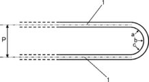
- the 0.2% proof stress of the seamless pipe exceeds the above range and the elongation is below the above range, strong processing with a small bending pitch P (for example, hairpin processing with a bending pitch P of 22 mm or less shown in FIG. 1) is performed. It becomes difficult to perform, and at the time of hairpin bending, wrinkles are generated in the inner part of the bend, the tube is flattened, or is damaged in an extreme case.
- the 0.2% proof stress of the seamless pipe is less than 100 MPa, the degree of bending and bending of the material will increase before being subjected to bending, and problems such as buckling and clogging are likely to occur in the bending process. Become.
- the bending pitch P is a distance between the tube axes (code
- Examples of seamless pipes that are wound in multiple layers on the level wound coil of the present invention include an inner surface smooth tube (bearing tube) in which inner surface grooves are not formed and an inner surface grooved tube in which inner surface grooves are formed.
- the outer diameter D of the seamless tube is the outer diameter of the tube in a cross section when the seamless tube is cut by a plane perpendicular to the tube axis direction, and the wall thickness t of the seamless tube. Is the thickness of the pipe in a cross section when the seamless pipe is cut along a plane perpendicular to the pipe axis direction.
- the outer diameter D of the seamless pipe is the outer diameter of the pipe in a cross section when the seamless pipe is cut by a plane perpendicular to the pipe axis direction.
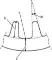
- the wall thickness t is the thickness of the pipe (bottom wall thickness) at the deepest position s of the inner groove in the cross section when the seamless pipe is cut along a plane perpendicular to the pipe axis direction. It is.
- the seamless pipe when manufacturing a cross fin tube heat exchanger, the seamless pipe is unwound from the inner or outer surface side of the level-wound coil, but when the seamless pipe is unwound from the level-wound coil. Since seamless hardening is added to the seamless pipe by extending the pipe, the 0.2% proof stress of the seamless pipe after being unwound becomes the 0.2% proof stress of the seamless pipe before being unrolled. Compared to increase. Therefore, the 0.2% proof stress of the seamless pipe wound around the level-wound coil (the seamless pipe before being unwound from the level-wound coil) is a hairpin bending process when manufacturing a cross fin tube type heat exchanger.
- the level wound coil must be designed so that the 0.2% proof stress ( ⁇ 0.2 ) of the seamless pipe wound is taken into account in the increment when unwinding.
- the level-wound coil of the present invention 0.2% of the rolled seamless pipe (seamless pipe before being unwound) is added in consideration of an increase in 0.2% proof stress that increases when unwound. Since the proof stress is defined in the above range, the 0.2% proof stress of the seamless pipe after being unwound for use in hairpin bending is 190 MPa or less, preferably 100 to 180 MPa. Therefore, the seamless tube unwound from the level wound coil of the present invention is excellent in hairpin bending workability. That is, according to the level wound coil of the present invention, a seamless tube excellent in hairpin bending workability can be provided.
- the tensile strength ( ⁇ B ), 0.2% proof stress ( ⁇ 0.2 ) and elongation ( ⁇ ) of the seamless pipe wound around the level wound coil are within the above ranges.
- the tensile strength ( ⁇ B ) of the seamless pipe after being unwound from the level wound coil, that is, the seamless pipe subjected to hairpin processing is 280 MPa or more, preferably 280 to 320 MPa.
- the 0.2% proof stress ( ⁇ 0.2 ) is 190 MPa or less, preferably 100 to 180 MPa, and the elongation ( ⁇ ) is 37% or more, preferably 37 to 52%. Therefore, the seamless tube unwound from the level wound coil of the present invention is a seamless tube that has high strength and can perform hairpin processing normally.
- the following method for producing a level-wound coil can be cited.
- the level-wound coil manufacturing method of the first aspect of the present invention (hereinafter also referred to as level-wound coil manufacturing method (1)) is a method of winding a level-wound coil manufacturing seamless tube in a multilayered arrangement in a cylindrical shape.
- a level-wound coil manufacturing method is characterized by producing a level-wound coil.
- a seamless pipe for level-wound coil production (seamless pipe before being wound around the level-wound coil) wound in an aligned multilayer winding is used as a seamless pipe for production of level-wound coil.
- tube (1) a seamless pipe for level-wound coil production
- the level wound coil manufacturing seamless pipe (1) used in the level wound coil manufacturing method (1) is made of Sn of 0.58 to 0.72 mass%, 0.005 to 0.035 mass% of Sn.
- the ratio (t / D) of the wall thickness (mm) to the outer diameter (mm) is 0.040 or less
- the tensile strength ( ⁇ B ) is 280 MPa or more
- 0.2% proof stress ( ⁇ 0 .2 ) is 170 MPa or less
- the elongation ( ⁇ ) is 38% or more.
- the material of the seamless pipe (1) for producing the level wound coil is the same as the material of the seamless pipe wound around the level wound coil of the present invention, containing Sn, Zr, Fe and P, and the remaining Cu and It is a copper alloy composed of inevitable impurities.
- the Sn content of the copper alloy forming the seamless pipe for producing the level wound coil is 0.58 to 0.72% by mass
- the Zr content is 0.005 to 0.035% by mass
- the Fe content is 0.01 to 0.10% by mass, preferably 0.06 to 0.10% by mass
- the P content is 0.004 to 0.040% by mass.
- outer diameter D and the wall thickness t of the seamless pipe (1) for producing the level wound coil are the same as the outer diameter D and the wall thickness t of the seamless pipe wound around the level wound coil of the present invention.
- the ratio (t / D) of the wall thickness (mm) to the outer diameter (mm) of the seamless pipe (1) for producing the level wound coil is 0.040 or less, preferably 0.020 to 0.040, particularly preferably. 0.030 to 0.038.
- the tensile strength ( ⁇ B ) of the seamless pipe (1) for producing the level wound coil is 280 MPa or more, preferably 280 to 320 MPa.
- the tensile strength ( ⁇ B ) of the seamless pipe (1) for producing the level wound coil can be 280 MPa or more, preferably 280 to 320 MPa.
- the 0.2% proof stress ( ⁇ 0.2 ) of the seamless pipe (1) for producing the level wound coil is 170 MPa or less, preferably 100 to 160 MPa. Since the 0.2% proof stress ( ⁇ 0.2 ) of the seamless pipe (1) for producing the level wound coil is in the above range, the seamless pipe after being wound around the level wound coil, that is, the level of the present invention
- the 0.2% proof stress ( ⁇ 0.2 ) of the seamless pipe wound around the wound coil can be 180 MPa or less, preferably 100 to 170 MPa.
- the elongation ( ⁇ ) of the seamless pipe (1) for producing the level wound coil is 38% or more, preferably 38 to 53%.
- the seamless pipe after being wound around the level wound coil, that is, the level wound coil of the present invention is wound.
- the elongation ( ⁇ ) of the seamless pipe can be 38% or more, preferably 38 to 53%.
- the level-wound coil manufacturing method (1) when a seamless pipe for producing a level-wound coil is wound into an aligned multi-layer winding in a cylindrical shape, work hardening by bending is added to the seamless pipe.
- the 0.2% yield strength of the seamless pipe after being wound around the wound coil is increased compared to the 0.2% yield strength of the seamless pipe before being wound around the level wound coil. Therefore, the 0.2% proof stress of the seamless pipe for level-wound coil production (the seamless pipe before being wound around the level-wound coil) is the seamless pipe (wrapped around the level-wound coil). It must be lower than the 0.2% proof stress of the seamless pipe after being turned. Therefore, the seamless pipe for producing the level wound coil must be designed in such a range that the 0.2% proof stress ( ⁇ 0.2 ) takes into account the increase when wound around the level wound coil. .
- the seamless pipe (1) for producing the level wound coil is 0.2% proof strength (before winding), taking into account the 0.2% proof strength increase that is increased when wound around the level wound coil. Since the 0.2% proof stress of the seamless pipe is defined in the above range, the 0.2% proof stress of the seamless pipe after being wound around the level wound coil is 180 MPa or less, preferably 100 to 170 MPa. Become.
- a method for manufacturing a seamless pipe (1) for producing a level wound coil will be described.
- the first form of the method for producing the seamless pipe (1) for producing the level-wound coil (hereinafter also referred to as the production method (1) of the seamless pipe (1) for producing the level-wound coil) is a seamless pipe. It is a manufacturing method in the case of an internal smooth tube.
- the second embodiment of the method for producing the seamless pipe (1) for producing the level wound coil (hereinafter also referred to as the production method (2) of the seamless pipe (1) for producing the level wound coil) is seamless. It is a manufacturing method in case a pipe
- a method (1) for producing a seamless pipe (1) for producing a level-wound coil obtains a copper alloy ingot having a chemical composition of a copper alloy that forms a seamless pipe wound around the level-wound coil of the present invention.
- This is a seamless pipe manufacturing method in which a casting process, a hot extrusion process, a cold working process, and a final heat treatment are sequentially performed, and no intermediate annealing process is performed between the hot extrusion process and the final heat treatment. .
- the casting process, the hot extrusion process, the cold working process, and the final heat treatment are sequentially performed. Note that performing these in order does not mean that the hot extrusion process is performed immediately after the casting process, the cold processing process is performed immediately after the hot extrusion process, and the final heat treatment is performed immediately after the cold processing process. It means that the hot extrusion process is performed after the process, the cold working process is performed after the hot extrusion process, and the final heat treatment is performed after the cold working process.
- the manufacturing method (2) of the seamless pipe (1) for producing a level-wound coil includes a copper alloy ingot having a chemical composition of a copper alloy that forms a seamless pipe wound around the level-wound coil of the present invention.
- a casting process, a hot extrusion process, a cold working process, an intermediate annealing process (A), a rolling process process, and a final heat treatment are sequentially performed, and a hot extrusion process and an intermediate annealing process (A ) Is a seamless pipe manufacturing method in which no other intermediate annealing treatment is performed.
- the rolling process process In the manufacturing method (2) of the seamless pipe (1) for producing the level wound coil, the casting process, the hot extrusion process, the cold working process, the intermediate annealing process (A), the rolling process process, Heat treatment is sequentially performed.
- performing these in order means that a hot extrusion process is performed immediately after the casting process, a cold processing process is performed immediately after the hot extrusion process, an intermediate annealing process (A) is performed immediately after the cold processing process, and an intermediate annealing process.
- the rolling process is performed immediately after the process (A), the final heat treatment is not performed immediately after the rolling process, the hot extrusion process is performed after the casting process, and the cold processing process is performed after the hot extrusion process.
- the intermediate annealing process (A) is performed after the cold working process, the rolling process process is performed after the intermediate annealing process (A), and the final heat treatment is performed after the rolling process process.
- the casting process according to the production method (1) of the seamless pipe (1) for producing the level wound coil (1) and the production method (2) of the seamless pipe (1) for producing the level wound coil is melted and cast according to a conventional method.
- This is a step of obtaining a billet in which a predetermined element is blended with a predetermined content.
- the Sn content of the billet is 0.58 to 0.72% by mass
- the Zr content is 0.005 to 0.035% by mass
- the Fe content is 0.01 to 0.10% by mass.
- the content is 0.06 to 0.10% by mass
- the P content is 0.004 to 0.040% by mass.
- a copper ingot, an in-process recycled material, a pure Sn ingot, a Cu—Zr master alloy, a Cu—Fe master alloy, a Cu—P master alloy, etc. are blended, Sn, Zr, Fe and The components are adjusted so that the P content becomes a predetermined content, and then the billet is cast using a high-frequency melting furnace or the like.
- the billet obtained by performing the casting process is then used.
- a hot extrusion process for hot extrusion is performed.
- the billet is heated at a predetermined temperature before hot extrusion, and then hot extrusion is performed.
- Hot extrusion is performed by mandrel extrusion. That is, hot extruding is performed with a mandrel inserted into a billet that has been previously perforated cold before heating, or a billet that has been perforated hot before extrusion to obtain a seamless hot extruded element tube. .
- the seamless hot-extrusion element tube obtained by performing the hot extrusion process is quickly cooled after the hot extrusion process.
- the cooling is performed by extruding the seamless hot-extrusion element tube into water or by introducing the seamless hot-extrusion element tube after hot extrusion into water.
- the cold extrusion of the seamless extruded element tube after cooling is performed.
- a cold working process is performed in which the outer diameter and thickness of the pipe are reduced.
- Cold working is cold drawing (drawing) or a combination of cold rolling with a tube laser and cold drawing (drawing).
- cold working such as rolling and drawing can be performed a plurality of times.
- the cold working step is performed in the cold. Refers to all processing.
- the production method (1) of the seamless pipe for level-wound coil production (1) is different from the production method (2) of the seamless pipe for production of level-wound coil (1). Each will be explained.
- the final heat treatment of the seamless element tube after the cold working obtained by performing the cold working process after the cold working process is performed.
- the holding temperature and holding time of the final heat treatment are appropriately selected so that the tensile strength ( ⁇ B ), 0.2% proof stress ( ⁇ 0.2 ) and elongation ( ⁇ ) of the seamless pipe are within a predetermined range.
- the In particular, the holding temperature of the final heat treatment is preferably in the range of 400 to 650 ° C. If the holding temperature of the final heat treatment is less than the above range, a long time heat treatment is required, so the productivity is lowered, and in some cases, annealing is insufficient, and if it exceeds the above range, significant grain growth occurs. Occurs and the strength and workability are reduced.
- the intermediate annealing process is not performed between the hot extrusion process and the final heat treatment.
- the degree (cross-sectional reduction rate) is 90% or more.
- the total degree of cold working process is the machining of the seamless tube after the last cold working performed in the cold working process for the first seamless steel pipe before the cold working performed in the cold working process. It indicates the degree and is represented by the cross-sectional reduction rate shown in the following formula (1).
- Cross-sectional reduction rate (%) ((cross-sectional area before processing of pipe ⁇ cross-sectional area after processing of pipe) / (cross-sectional area before processing of pipe)) ⁇ 100 (1)
- cross-sectional reduction rate (%) ((cross-sectional area before the first cold rolling of the tube ⁇ Cross sectional area after the last cold drawing of the tube) / (Cross sectional area before the first cold rolling of the tube)) ⁇ 100 ”.
- the intermediate annealing process is not performed and the cold working process is performed before the final heat treatment after the hot extrusion process.
- the tensile strength ( ⁇ B ) of the seamless pipe obtained by final annealing is 280 MPa or more, preferably 280 to 320 MPa.
- the 0.2% proof stress ( ⁇ 0.2 ) is 170 MPa or less, preferably 100 to 160 MPa, and the elongation ( ⁇ ) is 38% or more, preferably 38 to 53%.
- the seamless pipe (1) for producing the level-wound coil can be obtained.
- the cold-worked seamless pipe obtained by performing the cold-working process subsequent to the cold-working process is 400 to 400
- An intermediate annealing process (A) is performed by heating at a holding temperature of 700 ° C. By performing the intermediate annealing process (A), the rolling process in the rolling process is facilitated.
- the intermediate annealing process (A) is a heat treatment before the rolling process.
- a rolling process step is then performed in which the seamless pipe after the intermediate annealing treatment (A) is rolled.
- the rolling process is a process of forming a groove on the inner surface of the pipe material.
- the rolling process is performed by forming a spiral groove on the outer surface of the seamless pipe after the intermediate annealing (A). This is done by placing the formed plug and pressing it from the outside of the tube with a plurality of rolling balls rotating at high speed to transfer the groove of the formed plug to the inner surface of the tube.
- a rolling process process is performed after performing an intermediate annealing process (A), after performing a diameter reduction process.
- the inner surface grooved pipe after the rolling process obtained by performing the rolling process is then subjected to a final heat treatment.
- the holding temperature for the final heat treatment is preferably 400 to 650 ° C.
- the final heat treatment time is appropriately selected so that the tensile strength ( ⁇ B ), 0.2% proof stress ( ⁇ 0.2 ), and elongation ( ⁇ ) of the seamless pipe are within a predetermined range. .
- the manufacturing method (2) of the seamless pipe (1) for producing the level wound coil no other heat treatment such as intermediate annealing treatment is performed between the hot extrusion step and the intermediate annealing treatment (A).
- B ) is 280 MPa or more, preferably 280 to 320 MPa
- 0.2% proof stress ( ⁇ 0.2 ) is 170 MPa or less, preferably 100 to 160 MPa
- elongation ( ⁇ ) is 38% or more, preferably 38 to 53%. It can be.
- the total degree of cold working process is the processing of the seamless element tube after the cold working performed last in the cold working process for the first seamless element tube performed before the cold working process.
- Degree (degree (1)) is the total degree of cold working process after the cold working performed last in the cold working process for the first seamless element tube
- the seamless pipe (1) for producing the level-wound coil can be obtained.
- the seamless tube is an internally grooved tube, it is possible to maintain both the heat transfer performance and the bending workability of the tube by setting the dimensional parameters of the internal groove within the following range, preferable.
- ⁇ When fin height is h (mm) and wall thickness (bottom wall thickness) is t (mm), h / t is 0.50 to 1.2 ⁇
- lead angle is ⁇ (°) and fin apex angle is ⁇ (°) ⁇ / ⁇ is 0.70 or more
- the fin height h, the wall thickness (bottom wall thickness) t, and the fin apex angle ⁇ are denoted by symbols h, t, and ⁇ in FIG.
- the lead angle ⁇ is an inclination angle of the inner surface groove with respect to the tube axis direction of the seamless pipe.
- a level-wound coil of the present invention is manufactured by winding the seamless pipe (1) for producing a level-wound coil obtained in this manner into a cylindrical shape in multiple layers.
- a level-wound coil manufacturing method (hereinafter also referred to as a level-wound coil manufacturing method (2)) according to the second aspect of the present invention will be described.
- the material is Sn of 0.58 to 0.72 mass%, Zr of 0.005 to 0.035 mass%, 0.01 to 0.10 mass%, preferably A copper alloy containing 0.06 to 0.10% by mass of Fe and 0.004 to 0.040% by mass of P, with the remainder being Cu and inevitable impurities, and having a thickness (mm) relative to the outer diameter (mm)
- a seamless tube having a ratio (t / D) of 0.040 or less is aligned and wound in a cylindrical shape, and then subjected to heat treatment, and the tensile strength ( ⁇ B ) of the seamless tube after heat treatment is 280 MPa or more.
- the first form of the level-wound coil manufacturing method (2) is a manufacturing method in the case where the seamless tube is an inner surface smooth tube.
- the second form of the level wound coil manufacturing method (2) is a manufacturing method in the case where the seamless pipe is an internally grooved pipe.
- the first form of the level-wound coil manufacturing method (2) is a casting process for obtaining a copper alloy ingot having a chemical composition of a copper alloy that forms a seamless pipe wound around the level-wound coil of the present invention;
- a level-wound coil manufacturing method in which a hot extrusion process, a cold working process, a winding process, and a final heat treatment are sequentially performed, and no intermediate annealing process is performed between the hot extrusion process and the final heat treatment. is there.
- a casting process, a hot extrusion process, a cold working process, a winding process, and a final heat treatment are sequentially performed.
- performing these in order means that a hot extrusion process is performed immediately after the casting process, a cold working process is performed immediately after the hot extrusion process, a winding process is performed immediately after the cold working process, and a winding process is performed immediately after the winding process.
- This is not a final heat treatment, but a hot extrusion process after the casting process, a cold working process after the hot extrusion process, a winding process after the cold working process, and a final heat treatment after the winding process. It means to do.
- the second form of the level-wound coil manufacturing method (2) is a casting process for obtaining a copper alloy ingot having a chemical composition of a copper alloy that forms a seamless pipe wound around the level-wound coil of the present invention. Then, a hot extrusion process, a cold working process, an intermediate annealing process (A), a rolling process process, a winding process, and a final heat treatment are sequentially performed, and a hot extrusion process and an intermediate annealing process ( A level-wound coil manufacturing method in which no intermediate annealing process is performed between A and A).
- a casting process, a hot extrusion process, a cold working process, an intermediate annealing process (A), a rolling process process, a winding process, A final heat treatment is sequentially performed.
- performing these in order means that a hot extrusion process is performed immediately after the casting process, a cold processing process is performed immediately after the hot extrusion process, an intermediate annealing process (A) is performed immediately after the cold processing process, and an intermediate annealing process.
- the rolling process is performed immediately after the process (A), the winding process is performed immediately after the rolling process, the final heat treatment is performed immediately after the winding process, and the hot extrusion process is performed after the casting process.
- the cold working process is performed after the hot extrusion process
- the intermediate annealing process (A) is performed after the cold working process
- the rolling process process is performed after the intermediate annealing process (A)
- the winding process is performed after the rolling process process. It means that the final heat treatment is performed after the winding process.
- the first form of the level-wound coil manufacturing method (2) and the second form of the level-wound coil manufacturing method (2) are different, and will be described.
- the cold-worked seamless tube obtained by performing the cold-working process subsequent to the cold-working process is aligned and wound in a cylindrical manner.
- a winding process is performed in which the coil is wound up into the shape of the level-wound coil, and then the material wound into the shape of the level-wound coil is subjected to a final heat treatment.
- the holding temperature and holding time of the final heat treatment the tensile strength ( ⁇ B ), 0.2% proof stress ( ⁇ 0.2 ) and elongation ( ⁇ ) of the seamless pipe wound around the level wound coil are predetermined. It is appropriately selected so as to be in the range.
- the holding temperature of the final heat treatment is preferably in the range of 400 to 650 ° C. If the holding temperature of the final heat treatment is less than the above range, a long time heat treatment is required, so the productivity is lowered, and in some cases, annealing is insufficient, and if it exceeds the above range, significant grain growth occurs. Occurs and the strength and workability are reduced.
- the total workability (cross-section reduction
- the total degree of cold working process is the machining of the seamless tube after the last cold working performed in the cold working process for the first seamless steel pipe before the cold working performed in the cold working process. Degree (degree (1)).
- the intermediate annealing process is not performed, and the total degree of cold work process Is within the above range, and the retention temperature of the final heat treatment is within the above range
- 0.2% proof stress ( ⁇ 0.2 ) is 180 MPa or less, preferably 100 to 170 MPa
- elongation ( ⁇ ) is 38% or more, preferably 38 to 53%. be able to.
- the level wound coil of the present invention can be obtained by performing the first form of the method (2) for producing the level wound coil.
- the cold-worked seamless tube obtained by performing the cold-working process after the cold-working process is maintained at 400 to 700 ° C.
- the intermediate annealing process (A) heated at temperature is performed.
- the rolling process in the rolling process is facilitated.
- the intermediate annealing process (A) is a heat treatment before the rolling process.
- a rolling process for rolling the seamless tube after the intermediate annealing (A) is then performed.
- the rolling process is a process of forming a groove on the inner surface of the pipe material.
- the rolling process is performed by forming a spiral groove on the outer surface of the seamless pipe after the intermediate annealing (A). This is done by placing the formed plug and pressing it from the outside of the tube with a plurality of rolling balls rotating at high speed to transfer the groove of the formed plug to the inner surface of the tube.
- a rolling process process is performed after performing an intermediate annealing process (A), after performing a diameter reduction process.
- the inner grooved tube after the rolling process obtained by performing the rolling process is then aligned and wound in a cylindrical shape, that is, the level-wound A winding process for winding into the shape of the coil is performed, and then the final wound process is performed on the coil wound in the shape of the level wound coil.
- the holding temperature for the final heat treatment is preferably 400 to 650 ° C.
- the final heat treatment time is appropriately selected so that the tensile strength ( ⁇ B ), 0.2% proof stress ( ⁇ 0.2 ), and elongation ( ⁇ ) of the seamless pipe are within a predetermined range. .
- a seamless tube obtained by performing the final heat treatment by setting the total processing degree (section reduction rate) to 90% or more and setting the holding temperature of the final heat treatment within the above range.
- Tubeless has a tensile strength ( ⁇ B ) of 280 MPa or more, preferably 280 to 320 MPa, a 0.2% proof stress ( ⁇ 0.2 ) of 180 MPa or less, preferably 100 to 170 MPa, and an elongation ( ⁇ ) of 38. % Or more, preferably 38 to 53%.
- ⁇ B tensile strength
- ⁇ 0.2 0.2% proof stress
- ⁇ elongation
- the level wound coil of the present invention can be obtained by performing the second form of the method (2) for producing the level wound coil.
- the seamless tube is an internally grooved tube, it is possible to maintain both the heat transfer performance and the bending workability of the tube by setting the dimensional parameters of the internal groove within the following range, preferable.
- ⁇ When fin height is h (mm) and wall thickness (bottom wall thickness) is t (mm), h / t is 0.50 to 1.2 ⁇
- lead angle is ⁇ (°) and fin apex angle is ⁇ (°) ⁇ / ⁇ is 0.70 or more
- the fin height h, the wall thickness (bottom wall thickness) t, and the fin apex angle ⁇ are denoted by symbols h, t, and ⁇ in FIG.
- the lead angle ⁇ is an inclination angle of the inner surface groove with respect to the tube axis direction of the seamless pipe.
- the seamless tube before the final heat treatment contains Fe and P of Sn, Zr, and the balance Cu and inevitable impurities.
- the copper alloy has a Sn content of 0.58 to 0.72% by mass, a Zr content of 0.005 to 0.035% by mass, and an Fe content of 0%. 0.01 to 0.10% by mass, preferably 0.06 to 0.10% by mass, and the P content is 0.004 to 0.040% by mass.
- the outer diameter D and the wall thickness t of the seamless pipe before the final heat treatment are the seam wound around the level-wound coil of the present invention. It is the same as the outer diameter D and the wall thickness t of the tubeless.
- the ratio (t / D) of the wall thickness (mm) to the outer diameter (mm) of the seamless pipe before the final heat treatment is 0. 0.040 or less, preferably 0.020 to 0.040, particularly preferably 0.030 to 0.038.
- the cross fin tube type heat exchanger of the present invention is a cross fin tube type heat exchanger obtained by bending a seamless tube unwound from the level wound coil of the present invention into a hairpin and assembling it with aluminum fins.
- the cross fin tube heat exchanger according to the present invention includes a cross fin tube heat exchanger in which a seamless tube unwound from the level wound coil of the present invention is subjected to hairpin bending and assembled to an aluminum fin. It is a manufacturing method of the cross fin tube type heat exchanger characterized by obtaining.
- Example 1 A copper alloy ingot having chemical components shown in Table 1 was melted and cast to produce a billet for hot extrusion. (2) The billet was heated and subjected to hot extrusion at 930 ° C. to obtain an extruded raw tube. Next, the extruded extruded tube was extruded into water and quenched. -The inner diameter was about 75 mm perforated before extrusion. -The outer diameter of the extruded element tube was 102 mm, and the inner diameter was 75 mm. (3) The extruded blank was cold-rolled with a Birger mill to obtain a rolled blank.
- the rolling tube had an outer diameter of 46 mm and an inner diameter of 39.8 mm. -The degree of work in cold rolling (cross-sectional reduction rate) was 88.9%.
- Cross-sectional reduction rate (%) ((cross-sectional area before processing ⁇ cross-sectional area after processing) / cross-sectional area before processing) ⁇ 100 (4)
- the above-mentioned rolled blank was cold drawn a plurality of times to obtain a drawn blank.
- the outer diameter of the drawing element tube was 38 mm, and the inner diameter was 33 mm.
- the degree of work in the entire cold drawing was 33.3% in terms of cross-sectional reduction.
- the holding temperature is as shown in Table 1, the rate of temperature increase is 5.0 ° C / min from 25 ° C to the holding temperature, and the cooling rate is 2.2 ° C / min from the holding temperature to 25 ° C. It was. -Tensile strength ( ⁇ B ), 0.2% proof stress ( ⁇ 0.2 ) of the seamless pipe after the final heat treatment (the seamless pipe wound around the LWC, ie, the seamless pipe before unwinding), Elongation ( ⁇ ) is shown in Table 1.
- Wrinkle generation rate (%) (number of tubes with wrinkles / number of tubes tested) ⁇ 100 (II) Flatness
- Flatness ratio (%) ((maximum outer diameter ⁇ minimum outer diameter) / nominal outer diameter) ⁇ 100
- a measurement position is a 45 degree, 90 degree, and 135 degree position of a hairpin bending part, and a nominal outer diameter is 7.0 mm in this example.
- a nominal outer diameter is 7.0 mm in this example.
- 1, 45 degrees, 90 degrees, and 135 degrees of a hairpin bending part are the position (code
- the flatness of each seamless pipe tested was determined, and the average value of the flatness was 15% or less.
- the seamless pipe after the hairpin bending test is heated at 850 ° C. for 30 seconds under the same conditions as the temperature rise of the pipe at the time of brazing. Strength, 0.2% proof stress, elongation) were evaluated. The results are shown in Table 1.
- the tensile strength ( ⁇ B ), 0.2% proof stress ( ⁇ 0.2 ), and elongation ( ⁇ ) of the seamless pipe were measured according to JIS Z 2241.
- Example 2 The same procedure as in Example 1 was performed except that the copper alloy ingots having chemical components shown in Table 1 were melted and cast in (1). The results are shown in Table 1.
- Example 2 In (1), the copper alloy ingot having the chemical composition shown in Table 1 was melted and cast, and in (4), the rolling raw tube was cold-drawn a plurality of times, and the outer diameter was 12.7 mm and the inner diameter was 11. The same method as in Example 1 except that a 1 mm drawn element tube was obtained and that the original tube was subjected to ball rolling in (6) to obtain an internally grooved tube B having the following dimensions. I went there. The results are shown in Table 1. In addition, the workability of the entire cold drawing is 92.8% in terms of the cross-section reduction rate, and the total workability of cold rolling and cold drawing, that is, the total workability of cold work is the cross-section reduction rate. 99.2%.
- Example 3 (Examples 3 to 4 and Comparative Example 3) In the same manner as in Example 1, except that the copper alloy ingot having the chemical composition shown in Table 1 in (1) was melted and cast, and the final heat treatment was performed at the holding temperature shown in Table 1 in (7). went. The results are shown in Table 1.
- the seamless pipe unwound from the level wound coil of the present invention is a copper alloy seamless pipe having high strength and capable of normally performing hairpin bending, so that the heat transfer pipe made of copper alloy can be made thinner. It becomes possible.
Landscapes
- Chemical & Material Sciences (AREA)
- Engineering & Computer Science (AREA)
- Mechanical Engineering (AREA)
- Physics & Mathematics (AREA)
- Thermal Sciences (AREA)
- Materials Engineering (AREA)
- Metallurgy (AREA)
- Organic Chemistry (AREA)
- Crystallography & Structural Chemistry (AREA)
- General Engineering & Computer Science (AREA)
- Metal Extraction Processes (AREA)
- Winding, Rewinding, Material Storage Devices (AREA)
Abstract
Description
該レベルワウンドコイルに巻かれている該継目無管の材質が、0.58~0.72質量%のSn、0.005~0.035質量%のZr、0.01~0.10質量%のFe及び0.004~0.040質量%のPを含有し、残部Cu及び不可避不純物からなる銅合金であり、
該レベルワウンドコイルに巻かれている該継目無管の外径(mm)に対する肉厚(mm)の比(t/D)が0.040以下であり、
該レベルワウンドコイルに巻かれている継目無管の引張強さ(σB)が280MPa以上であり、0.2%耐力(σ0.2)が180MPa以下であり、伸び(δ)が38%以上であること、
を特徴とするレベルワウンドコイルを提供するものである。
該レベルワウンドコイルに巻かれている該継目無管の材質が、0.58~0.72質量%のSn、0.005~0.035質量%のZr、0.01~0.10質量%のFe及び0.004~0.040質量%のPを含有し、残部Cu及び不可避不純物からなる銅合金であり、
該レベルワウンドコイルに巻かれている該継目無管の外径(mm)に対する肉厚(mm)の比(t/D)が0.040以下であり、
該レベルワウンドコイルに巻かれている継目無管の引張強さ(σB)が280MPa以上であり、0.2%耐力(σ0.2)が180MPa以下であり、伸び(δ)が38%以上であること、
を特徴とするレベルワウンドコイルである。
断面減少率(%)=((管の加工前の断面積-管の加工後の断面積)/(管の加工前の断面積))×100 (1)
例えば、冷間加工工程で、冷間圧延を複数回行い、次いで、冷間での抽伸を複数回行う場合、「断面減少率(%)=((管の最初の冷間圧延前の断面積-管の最後の冷間抽伸後の断面積)/(管の最初の冷間圧延前の断面積))×100」となる。
・フィン高さをh(mm)、肉厚(底肉厚)をt(mm)としたとき、
h/tが、0.50~1.2
・リード角をθ(°)、フィン頂角をα(°)としたとき、
θ/αが、0.70以上
なお、フィン高さh、肉厚(底肉厚)t、フィン頂角αは、図2中の符号h、t及びαである。また、リード角θとは、継目無管の管軸方向に対する内面溝の傾斜角である。
・フィン高さをh(mm)、肉厚(底肉厚)をt(mm)としたとき、
h/tが、0.50~1.2
・リード角をθ(°)、フィン頂角をα(°)としたとき、
θ/αが、0.70以上
なお、フィン高さh、肉厚(底肉厚)t、フィン頂角αは、図2中の符号h、t及びαである。また、リード角θとは、継目無管の管軸方向に対する内面溝の傾斜角である。
(実施例1)
(1)表1に示す化学成分の銅合金鋳塊を溶解及び鋳造し、熱間押出用のビレットを作製した。
(2)上記ビレットを加熱し、930℃にて熱間押出を行い、押出素管を得た。次いで、熱間押出した押出素管を、水中に押出して急冷した。
・押出前に熱間で内径約75mm穿孔した。
・押出素管の外径は102mm、内径は75mmであった。
(3)上記押出素管を、ビルガーミル圧延機によって冷間圧延し、圧延素管を得た。
・圧延素管の外径は46mm、内径は39.8mmであった。
・冷間圧延での加工度(断面減少率)は、88.9%であった。
断面減少率(%)=((加工前の断面積-加工後の断面積)/加工前の断面積)×100
(4)上記の圧延素管を、冷間にて抽伸を複数回行い、抽伸素管を得た。
・抽伸素管の外径は38mm、内径は33mmであった。
・冷間抽伸全体での加工度は、断面減少率で33.3%であった。
・冷間圧延及び冷間抽伸の総加工度、すなわち、冷間加工の総加工度は、断面減少率で92.6%であった。
(5)上記の抽伸素管を中間焼鈍し、転造工程に供するための原管を得た。
・中間焼鈍条件は、表1に示す通り。
・原管の0.2%耐力(σ0.2)を、表1に示す。
(6)上記の原管を、ボール転造加工して、下記寸法諸元の内面溝付管Aを得た。
<内面溝付管Aの寸法諸元>
・外径:7.0mm
・肉厚(図2中、符号t):0.26mm
・フィン高さ(図2中、符号h):0.22mm
・フィン頂角(図2中、符号α):13°
・溝条数:44条
・リード角θ:28°
・内面溝付管の外径(mm)に対する肉厚(mm)の比(t/D):0.037
(7)上記の内面溝付管を、内側面から巻き解かれる方式の円筒状の整列多層巻きに巻き取った。次いで、下記の条件の最終熱処理を行い、レベルワウンドコイル(LWC)を得た。
・熱処理方法:ローラーハース連続焼鈍炉にて行った。
・条件:保持温度は表1に示す通りであり、昇温速度は25℃から保持温度まで5.0℃/分であり、冷却速度は保持温度から25℃まで2.2℃/分であった。
・最終熱処理後の継目無管(LWCに巻かれている継目無管、すなわち、巻き解き前の継目無管)の引張強さ(σB)、0.2%耐力(σ0.2)、伸び(δ)を表1に示す。
(8)上記のLWCの内面側から継目無管を巻き解き、ヘアピン加工供試の継目無管(巻き解き後の継目無管、すなわち、クロスフィンチューブ型熱交換器の伝熱管作製用の継目無管)を得た。
・ヘアピン加工供試の継目無管の引張強さ(σB)、0.2%耐力(σ0.2)及び伸び(δ)を表1に示す。
(9)上記のヘアピン加工供試の継目無管(巻き解き後の継目無管)を用い、下記の条件にてヘアピン曲げ加工試験を行い、加工性を評価した。その結果を表1に示す。
・ヘアピン曲げ加工試験の方法:片首振りボールマンドレルの肩部と曲げ金型の曲げ開始位置が一直線上に並んだ位置を0点とし、曲げ型R部から遠ざかる方向へマンドレル位置を2.0~5.5mmの範囲でずらしながら、ヘアピン加工性の評価を行った。
・ヘアピン曲げ加工試験の条件:ボールマンドレル外径が5.90mm、曲げピッチが22mm
・各実施例及び比較例の継目無管について、20本ずつ試験を行った。
<評価>
(I)しわ発生
ヘアピン曲げの内側部分にしわが発生している継目無管の数を数え、下記式にて、しわ発生率を求めた。しわ発生率が0%の場合を合格とした。
しわ発生率(%)=(しわが発生した管の本数/試験した管の本数)×100
(II)扁平率
ヘアピン曲げ後の曲げ部の扁平率を下記にて算出した。
扁平率(%)=((最大外径-最小外径)/呼称外径)×100
なお、測定位置は、ヘアピン曲げ部の45°、90°、135°位置であり、呼称外径は、本例では7.0mmである。なお、ヘアピン曲げ部の45°、90°、135°とは、図1に示すように、継目無管を45°曲げた位置(符号a)、90°曲げた位置(符号b)、135°曲げた位置(符号c)である。
試験した各継目無管の扁平率を求め、扁平率の平均値が15%以下の場合を合格とした。
(10)上記ヘアピン曲げ加工試験を行った後の継目無管を、ろう付け時の管の温度上昇と同等の条件として、850℃で30秒間の加熱を行い、加熱後の機械的性質(引張強さ、0.2%耐力、伸び)を評価した。その結果を表1に示す。
<引張強さ(σB)、0.2%耐力(σ0.2)、伸び(δ)>
継目無管の引張強さ(σB)、0.2%耐力(σ0.2)、伸び(δ)は、JIS Z 2241に準拠して測定した。
(1)において表1に示す化学成分の銅合金鋳塊を溶解及び鋳造したこと、及び(7)において表1に示す保持温度で最終熱処理をしたこと以外は、実施例1と同様の方法で行った。その結果を表1に示す。
(1)において表1に示す化学成分の銅合金鋳塊を溶解及び鋳造したこと以外は、実施例1と同様の方法で行った。その結果を表1に示す。
(1)において表1に示す化学成分の銅合金鋳塊を溶解及び鋳造したこと、(4)において圧延素管を、冷間にて抽伸を複数回行い、外径12.7mm、内径11.1mmの抽伸素管を得たこと、及び(6)において原管を、ボール転造加工して、下記寸法諸元の内面溝付管Bを得たこと以外は、実施例1と同様の方法で行った。その結果を表1に示す。なお、冷間抽伸全体での加工度は、断面減少率で92.8%であり、冷間圧延及び冷間抽伸の総加工度、すなわち、冷間加工の総加工度は、断面減少率で99.2%である。
<内面溝付管Bの寸法諸元>
・外径:7.0mm
・肉厚(図2中、符号t):0.23mm
・フィン高さ(図2中、符号h):0.22mm
・フィン頂角(図2中、符号α):13°
・溝条数:44条
・リード角θ:28°
・内面溝付管の外径(mm)に対する肉厚(mm)の比(t/D):0.033
(1)において表1に示す化学成分の銅合金鋳塊を溶解及び鋳造したこと、及び(7)において表1に示す保持温度で最終熱処理をしたこと以外は、実施例1と同様の方法で行った。その結果を表1に示す。

P 曲げピッチ
t 肉厚(底肉厚)
h フィン高さ
s 内面溝の最も深い位置
α フィン頂角
Claims (9)
- 継目無管が円筒状に整列多層巻きされているレベルワウンドコイルであり、
該レベルワウンドコイルに巻かれている該継目無管の材質が、0.58~0.72質量%のSn、0.005~0.035質量%のZr、0.01~0.10質量%のFe及び0.004~0.040質量%のPを含有し、残部Cu及び不可避不純物からなる銅合金であり、
該レベルワウンドコイルに巻かれている該継目無管の外径(mm)に対する肉厚(mm)の比(t/D)が0.040以下であり、
該レベルワウンドコイルに巻かれている継目無管の引張強さ(σB)が280MPa以上であり、0.2%耐力(σ0.2)が180MPa以下であり、伸び(δ)が38%以上であること、
を特徴とするレベルワウンドコイル。 - 前記銅合金のFeの含有量が0.06~0.10質量%であることを特徴とする請求項1記載のレベルワウンドコイル。
- 前記レベルワウンドコイルが、コイル軸を垂直に配置して、前記コイルの円筒状の内面側から前記継目無管が巻き解かれるレベルワウンドコイルであることを特徴とする請求項1又は2いずれか1項記載のレベルワウンドコイル。
- 材質が、0.58~0.72質量%のSn、0.005~0.035質量%のZr、0.01~0.10質量%のFe及び0.004~0.040質量%のPを含有し、残部Cu及び不可避不純物からなる銅合金であり、外径(mm)に対する肉厚(mm)の比(t/D)が0.040以下であり、引張強さ(σB)が280MPa以上であり、0.2%耐力(σ0.2)が170MPa以下であり、伸び(δ)が38%以上であるレベルワウンドコイル作製用継目無管を、円筒状に整列多層巻きして、レベルワウンドコイルを作製することを特徴とするレベルワウンドコイルの製造方法。
- 前記銅合金のFeの含有量が0.06~0.10質量%であることを特徴とする請求項4記載のレベルワウンドコイルの製造方法。
- 材質が、0.58~0.72質量%のSn、0.005~0.035質量%のZr、0.01~0.10質量%のFe及び0.004~0.040質量%のPを含有し、残部Cu及び不可避不純物からなる銅合金であり、外径(mm)に対する肉厚(mm)の比(t/D)が0.040以下の継目無管を、円筒状に整列多層巻きし、次いで、熱処理を行い、熱処理後の継目無管の引張強さ(σB)が280MPa以上であり、0.2%耐力(σ0.2)が180MPa以下であり、伸び(δ)が38%以上であるレベルワウンドコイルを作製することを特徴とするレベルワウンドコイルの製造方法。
- 前記銅合金のFeの含有量が0.06~0.10質量%であることを特徴とする請求項6記載のレベルワウンドコイルの製造方法。
- 請求項1~3いずれか1項記載のレベルワウンドコイルより巻き解いた継目無管をヘアピン曲げし、アルミニウムフィンに組み付けることにより得られたクロスフィンチューブ熱交換器。
- 請求項1~3いずれか1項記載のレベルワウンドコイルより巻き解いた継目無管をヘアピン曲げし、アルミニウムフィンに組み付けて、クロスフィンチューブ型熱交換器を得ることを特徴とするクロスフィンチューブ熱交換器の製造方法。
Priority Applications (2)
| Application Number | Priority Date | Filing Date | Title |
|---|---|---|---|
| CN201380019902.3A CN104428430A (zh) | 2012-04-16 | 2013-04-10 | 平绕盘管、平绕盘管的制造方法、交叉翅片管型热交换器以及交叉翅片管型热交换器的制造方法 |
| KR1020147031634A KR20150003311A (ko) | 2012-04-16 | 2013-04-10 | 레벨 와운드 코일, 레벨 와운드 코일의 제조 방법, 크로스 핀 튜브형 열교환기 및 크로스 핀 튜브형 열교환기의 제조 방법 |
Applications Claiming Priority (2)
| Application Number | Priority Date | Filing Date | Title |
|---|---|---|---|
| JP2012092592 | 2012-04-16 | ||
| JP2012-092592 | 2012-04-16 |
Publications (1)
| Publication Number | Publication Date |
|---|---|
| WO2013157461A1 true WO2013157461A1 (ja) | 2013-10-24 |
Family
ID=49383420
Family Applications (1)
| Application Number | Title | Priority Date | Filing Date |
|---|---|---|---|
| PCT/JP2013/060825 Ceased WO2013157461A1 (ja) | 2012-04-16 | 2013-04-10 | レベルワウンドコイル、レベルワウンドコイルの製造方法、クロスフィンチューブ型熱交換器及びクロスフィンチューブ型熱交換器の製造方法 |
Country Status (4)
| Country | Link |
|---|---|
| JP (1) | JPWO2013157461A1 (ja) |
| KR (1) | KR20150003311A (ja) |
| CN (1) | CN104428430A (ja) |
| WO (1) | WO2013157461A1 (ja) |
Citations (3)
| Publication number | Priority date | Publication date | Assignee | Title |
|---|---|---|---|---|
| JP2005289593A (ja) * | 2004-03-31 | 2005-10-20 | Kobelco & Materials Copper Tube Inc | レベルワウンドコイル、レベルワウンドコイルの梱包体及びレベルワウンドコイルからの管の供給方法 |
| JP2006274313A (ja) * | 2005-03-28 | 2006-10-12 | Kobelco & Materials Copper Tube Inc | 熱交換器用銅合金管及びその製造方法 |
| JP2008255381A (ja) * | 2007-03-30 | 2008-10-23 | Kobelco & Materials Copper Tube Inc | 耐熱高強度熱交換器用銅合金管 |
Family Cites Families (4)
| Publication number | Priority date | Publication date | Assignee | Title |
|---|---|---|---|---|
| JPS5839900B2 (ja) * | 1977-12-29 | 1983-09-02 | 三菱マテリアル株式会社 | 継目無し管製造用Cu合金 |
| DE102006013384B4 (de) * | 2006-03-23 | 2009-10-22 | Wieland-Werke Ag | Verwendung eines Wärmeaustauscherrohrs |
| JP4630323B2 (ja) * | 2007-10-23 | 2011-02-09 | 株式会社コベルコ マテリアル銅管 | 破壊強度に優れた熱交換器用銅合金管 |
| JP5371271B2 (ja) * | 2008-03-21 | 2013-12-18 | 住友軽金属工業株式会社 | クロスフィンチューブ型熱交換器用銅管 |
-
2013
- 2013-04-10 WO PCT/JP2013/060825 patent/WO2013157461A1/ja not_active Ceased
- 2013-04-10 KR KR1020147031634A patent/KR20150003311A/ko not_active Withdrawn
- 2013-04-10 CN CN201380019902.3A patent/CN104428430A/zh active Pending
- 2013-04-10 JP JP2014511182A patent/JPWO2013157461A1/ja active Pending
Patent Citations (3)
| Publication number | Priority date | Publication date | Assignee | Title |
|---|---|---|---|---|
| JP2005289593A (ja) * | 2004-03-31 | 2005-10-20 | Kobelco & Materials Copper Tube Inc | レベルワウンドコイル、レベルワウンドコイルの梱包体及びレベルワウンドコイルからの管の供給方法 |
| JP2006274313A (ja) * | 2005-03-28 | 2006-10-12 | Kobelco & Materials Copper Tube Inc | 熱交換器用銅合金管及びその製造方法 |
| JP2008255381A (ja) * | 2007-03-30 | 2008-10-23 | Kobelco & Materials Copper Tube Inc | 耐熱高強度熱交換器用銅合金管 |
Non-Patent Citations (1)
| Title |
|---|
| "Improvement of Yield Strength for Heat- Resistance Copper Alloy Tube by Fe Addition", JOURNAL OF THE JRICU, vol. 45, no. 1, 2006, pages 291 - 294 * |
Also Published As
| Publication number | Publication date |
|---|---|
| JPWO2013157461A1 (ja) | 2015-12-21 |
| KR20150003311A (ko) | 2015-01-08 |
| CN104428430A (zh) | 2015-03-18 |
Similar Documents
| Publication | Publication Date | Title |
|---|---|---|
| KR101053007B1 (ko) | 열교환기용 구리합금관 | |
| JP6388398B2 (ja) | 熱交換器用内面溝付管及びその製造方法 | |
| CN102575319B (zh) | 铜合金无缝管 | |
| JP6114939B2 (ja) | 継目無管、レベルワウンドコイル及びクロスフィンチューブ型熱交換器及びその製造方法 | |
| JP2008174785A (ja) | 熱交換器用銅合金管 | |
| JP5132845B2 (ja) | 継目無管、コイル、レベルワウンドコイル、レベルワウンドコイルの製造方法、クロスフィンチューブ型熱交換器及びクロスフィンチューブ型熱交換器の製造方法 | |
| JP2014109040A (ja) | レベルワウンドコイル、レベルワウンドコイルの製造方法、クロスフィンチューブ型熱交換器及びクロスフィンチューブ型熱交換器の製造方法 | |
| JP5404139B2 (ja) | 熱交換器用銅合金管 | |
| JP6101969B2 (ja) | レベルワウンドコイル、レベルワウンドコイルの製造方法、クロスフィンチューブ型熱交換器及びクロスフィンチューブ型熱交換器の製造方法 | |
| WO2018061277A1 (ja) | 高耐食性銅管 | |
| JP2017036468A (ja) | 銅合金管 | |
| JP6244213B2 (ja) | 熱交換器用銅管 | |
| WO2013157461A1 (ja) | レベルワウンドコイル、レベルワウンドコイルの製造方法、クロスフィンチューブ型熱交換器及びクロスフィンチューブ型熱交換器の製造方法 | |
| JP5208562B2 (ja) | 継目無管 | |
| WO2014142049A1 (ja) | 伝熱管用銅合金継目無管 | |
| JP2014109041A (ja) | レベルワウンドコイル、レベルワウンドコイルの製造方法、クロスフィンチューブ型熱交換器及びクロスフィンチューブ型熱交換器の製造方法 | |
| JP5990496B2 (ja) | 熱交換器用りん脱酸銅管 | |
| JP6360363B2 (ja) | 銅合金管 | |
| JP6402043B2 (ja) | 高強度銅合金管 | |
| JP2011094176A (ja) | 銅合金継目無管 | |
| JP2011094175A (ja) | 銅合金継目無管 | |
| JP2016180170A (ja) | 銅合金管 | |
| JP2016180169A (ja) | 銅合金管 |
Legal Events
| Date | Code | Title | Description |
|---|---|---|---|
| 121 | Ep: the epo has been informed by wipo that ep was designated in this application |
Ref document number: 13778733 Country of ref document: EP Kind code of ref document: A1 |
|
| ENP | Entry into the national phase |
Ref document number: 2014511182 Country of ref document: JP Kind code of ref document: A |
|
| NENP | Non-entry into the national phase |
Ref country code: DE |
|
| ENP | Entry into the national phase |
Ref document number: 20147031634 Country of ref document: KR Kind code of ref document: A |
|
| 122 | Ep: pct application non-entry in european phase |
Ref document number: 13778733 Country of ref document: EP Kind code of ref document: A1 |