WO2013154125A1 - 光学部材、偏光板のセットおよび液晶表示装置 - Google Patents
光学部材、偏光板のセットおよび液晶表示装置 Download PDFInfo
- Publication number
- WO2013154125A1 WO2013154125A1 PCT/JP2013/060785 JP2013060785W WO2013154125A1 WO 2013154125 A1 WO2013154125 A1 WO 2013154125A1 JP 2013060785 W JP2013060785 W JP 2013060785W WO 2013154125 A1 WO2013154125 A1 WO 2013154125A1
- Authority
- WO
- WIPO (PCT)
- Prior art keywords
- liquid crystal
- layer
- polarizing plate
- optical member
- light
- Prior art date
Links
- 239000004973 liquid crystal related substance Substances 0.000 title claims abstract description 140
- 230000003287 optical effect Effects 0.000 title claims abstract description 77
- 238000009792 diffusion process Methods 0.000 claims abstract description 92
- 239000000853 adhesive Substances 0.000 claims description 42
- 230000001070 adhesive effect Effects 0.000 claims description 40
- 210000002858 crystal cell Anatomy 0.000 claims description 27
- 239000010410 layer Substances 0.000 abstract description 164
- 239000011241 protective layer Substances 0.000 abstract description 18
- 239000000463 material Substances 0.000 description 41
- 239000012790 adhesive layer Substances 0.000 description 23
- 239000010419 fine particle Substances 0.000 description 23
- NLKNQRATVPKPDG-UHFFFAOYSA-M potassium iodide Chemical compound [K+].[I-] NLKNQRATVPKPDG-UHFFFAOYSA-M 0.000 description 21
- 239000004372 Polyvinyl alcohol Substances 0.000 description 20
- 230000000052 comparative effect Effects 0.000 description 20
- 238000000034 method Methods 0.000 description 20
- 230000010287 polarization Effects 0.000 description 20
- 229920002451 polyvinyl alcohol Polymers 0.000 description 20
- 230000005684 electric field Effects 0.000 description 19
- 239000004820 Pressure-sensitive adhesive Substances 0.000 description 17
- 229910052740 iodine Inorganic materials 0.000 description 17
- 239000011630 iodine Substances 0.000 description 17
- 230000005540 biological transmission Effects 0.000 description 16
- 239000000758 substrate Substances 0.000 description 16
- NIXOWILDQLNWCW-UHFFFAOYSA-N 2-Propenoic acid Natural products OC(=O)C=C NIXOWILDQLNWCW-UHFFFAOYSA-N 0.000 description 15
- ZCYVEMRRCGMTRW-UHFFFAOYSA-N 7553-56-2 Chemical compound [I] ZCYVEMRRCGMTRW-UHFFFAOYSA-N 0.000 description 15
- 229920005989 resin Polymers 0.000 description 15
- 239000011347 resin Substances 0.000 description 15
- 238000002834 transmittance Methods 0.000 description 15
- 238000010521 absorption reaction Methods 0.000 description 14
- 238000001035 drying Methods 0.000 description 12
- 238000011156 evaluation Methods 0.000 description 12
- 239000007864 aqueous solution Substances 0.000 description 11
- 239000011159 matrix material Substances 0.000 description 10
- KGBXLFKZBHKPEV-UHFFFAOYSA-N boric acid Chemical compound OB(O)O KGBXLFKZBHKPEV-UHFFFAOYSA-N 0.000 description 9
- 239000004327 boric acid Substances 0.000 description 9
- 239000002245 particle Substances 0.000 description 8
- -1 and the like Chemical class 0.000 description 7
- 239000000084 colloidal system Substances 0.000 description 7
- 239000000243 solution Substances 0.000 description 7
- 210000004027 cell Anatomy 0.000 description 6
- 229920003229 poly(methyl methacrylate) Polymers 0.000 description 6
- 229920000642 polymer Polymers 0.000 description 6
- 239000004926 polymethyl methacrylate Substances 0.000 description 6
- 230000008569 process Effects 0.000 description 6
- 239000004925 Acrylic resin Substances 0.000 description 5
- 239000003522 acrylic cement Substances 0.000 description 5
- 230000000694 effects Effects 0.000 description 5
- 238000004519 manufacturing process Methods 0.000 description 5
- 238000000926 separation method Methods 0.000 description 5
- 229920000178 Acrylic resin Polymers 0.000 description 4
- KKEYFWRCBNTPAC-UHFFFAOYSA-N Terephthalic acid Chemical compound OC(=O)C1=CC=C(C(O)=O)C=C1 KKEYFWRCBNTPAC-UHFFFAOYSA-N 0.000 description 4
- PNEYBMLMFCGWSK-UHFFFAOYSA-N aluminium oxide Inorganic materials [O-2].[O-2].[O-2].[Al+3].[Al+3] PNEYBMLMFCGWSK-UHFFFAOYSA-N 0.000 description 4
- 230000007547 defect Effects 0.000 description 4
- 238000004043 dyeing Methods 0.000 description 4
- 238000007654 immersion Methods 0.000 description 4
- XMBWDFGMSWQBCA-UHFFFAOYSA-M iodide Chemical compound [I-] XMBWDFGMSWQBCA-UHFFFAOYSA-M 0.000 description 4
- 150000002736 metal compounds Chemical class 0.000 description 4
- 229920006254 polymer film Polymers 0.000 description 4
- ILJSQTXMGCGYMG-UHFFFAOYSA-N triacetic acid Chemical compound CC(=O)CC(=O)CC(O)=O ILJSQTXMGCGYMG-UHFFFAOYSA-N 0.000 description 4
- 229920002799 BoPET Polymers 0.000 description 3
- 229920002284 Cellulose triacetate Polymers 0.000 description 3
- DKNPRRRKHAEUMW-UHFFFAOYSA-N Iodine aqueous Chemical compound [K+].I[I-]I DKNPRRRKHAEUMW-UHFFFAOYSA-N 0.000 description 3
- NNLVGZFZQQXQNW-ADJNRHBOSA-N [(2r,3r,4s,5r,6s)-4,5-diacetyloxy-3-[(2s,3r,4s,5r,6r)-3,4,5-triacetyloxy-6-(acetyloxymethyl)oxan-2-yl]oxy-6-[(2r,3r,4s,5r,6s)-4,5,6-triacetyloxy-2-(acetyloxymethyl)oxan-3-yl]oxyoxan-2-yl]methyl acetate Chemical compound O([C@@H]1O[C@@H]([C@H]([C@H](OC(C)=O)[C@H]1OC(C)=O)O[C@H]1[C@@H]([C@@H](OC(C)=O)[C@H](OC(C)=O)[C@@H](COC(C)=O)O1)OC(C)=O)COC(=O)C)[C@@H]1[C@@H](COC(C)=O)O[C@@H](OC(C)=O)[C@H](OC(C)=O)[C@H]1OC(C)=O NNLVGZFZQQXQNW-ADJNRHBOSA-N 0.000 description 3
- 238000007796 conventional method Methods 0.000 description 3
- 230000005865 ionizing radiation Effects 0.000 description 3
- 238000002156 mixing Methods 0.000 description 3
- KYTZHLUVELPASH-UHFFFAOYSA-N naphthalene-1,2-dicarboxylic acid Chemical compound C1=CC=CC2=C(C(O)=O)C(C(=O)O)=CC=C21 KYTZHLUVELPASH-UHFFFAOYSA-N 0.000 description 3
- 229920003207 poly(ethylene-2,6-naphthalate) Polymers 0.000 description 3
- 229920000515 polycarbonate Polymers 0.000 description 3
- 239000004417 polycarbonate Substances 0.000 description 3
- 239000011112 polyethylene naphthalate Substances 0.000 description 3
- 238000006116 polymerization reaction Methods 0.000 description 3
- 229920000098 polyolefin Polymers 0.000 description 3
- 239000011342 resin composition Substances 0.000 description 3
- 238000007127 saponification reaction Methods 0.000 description 3
- 239000000126 substance Substances 0.000 description 3
- 229920005992 thermoplastic resin Polymers 0.000 description 3
- 229920002554 vinyl polymer Polymers 0.000 description 3
- 238000005406 washing Methods 0.000 description 3
- XLYOFNOQVPJJNP-UHFFFAOYSA-N water Substances O XLYOFNOQVPJJNP-UHFFFAOYSA-N 0.000 description 3
- 229920001634 Copolyester Polymers 0.000 description 2
- VGGSQFUCUMXWEO-UHFFFAOYSA-N Ethene Chemical compound C=C VGGSQFUCUMXWEO-UHFFFAOYSA-N 0.000 description 2
- 239000005977 Ethylene Substances 0.000 description 2
- VQTUBCCKSQIDNK-UHFFFAOYSA-N Isobutene Chemical compound CC(C)=C VQTUBCCKSQIDNK-UHFFFAOYSA-N 0.000 description 2
- 229920000877 Melamine resin Polymers 0.000 description 2
- OKKJLVBELUTLKV-UHFFFAOYSA-N Methanol Chemical group OC OKKJLVBELUTLKV-UHFFFAOYSA-N 0.000 description 2
- 239000004642 Polyimide Substances 0.000 description 2
- 238000010306 acid treatment Methods 0.000 description 2
- 239000000654 additive Substances 0.000 description 2
- 230000000996 additive effect Effects 0.000 description 2
- 230000002411 adverse Effects 0.000 description 2
- 239000004020 conductor Substances 0.000 description 2
- 239000000470 constituent Substances 0.000 description 2
- 229920001577 copolymer Polymers 0.000 description 2
- 125000004122 cyclic group Chemical group 0.000 description 2
- 239000006185 dispersion Substances 0.000 description 2
- UHESRSKEBRADOO-UHFFFAOYSA-N ethyl carbamate;prop-2-enoic acid Chemical compound OC(=O)C=C.CCOC(N)=O UHESRSKEBRADOO-UHFFFAOYSA-N 0.000 description 2
- 230000014509 gene expression Effects 0.000 description 2
- 230000009477 glass transition Effects 0.000 description 2
- 239000007788 liquid Substances 0.000 description 2
- 239000000203 mixture Substances 0.000 description 2
- 239000000178 monomer Substances 0.000 description 2
- 230000000474 nursing effect Effects 0.000 description 2
- 229920000728 polyester Polymers 0.000 description 2
- 229920001225 polyester resin Polymers 0.000 description 2
- 239000004645 polyester resin Substances 0.000 description 2
- 229920001721 polyimide Polymers 0.000 description 2
- 229920002050 silicone resin Polymers 0.000 description 2
- 238000010186 staining Methods 0.000 description 2
- 238000012360 testing method Methods 0.000 description 2
- SMZOUWXMTYCWNB-UHFFFAOYSA-N 2-(2-methoxy-5-methylphenyl)ethanamine Chemical compound COC1=CC=C(C)C=C1CCN SMZOUWXMTYCWNB-UHFFFAOYSA-N 0.000 description 1
- PYSRRFNXTXNWCD-UHFFFAOYSA-N 3-(2-phenylethenyl)furan-2,5-dione Chemical compound O=C1OC(=O)C(C=CC=2C=CC=CC=2)=C1 PYSRRFNXTXNWCD-UHFFFAOYSA-N 0.000 description 1
- QTBSBXVTEAMEQO-UHFFFAOYSA-M Acetate Chemical compound CC([O-])=O QTBSBXVTEAMEQO-UHFFFAOYSA-M 0.000 description 1
- HRPVXLWXLXDGHG-UHFFFAOYSA-N Acrylamide Chemical compound NC(=O)C=C HRPVXLWXLXDGHG-UHFFFAOYSA-N 0.000 description 1
- NLHHRLWOUZZQLW-UHFFFAOYSA-N Acrylonitrile Chemical compound C=CC#N NLHHRLWOUZZQLW-UHFFFAOYSA-N 0.000 description 1
- 239000004986 Cholesteric liquid crystals (ChLC) Substances 0.000 description 1
- 239000004593 Epoxy Substances 0.000 description 1
- LFQSCWFLJHTTHZ-UHFFFAOYSA-N Ethanol Chemical compound CCO LFQSCWFLJHTTHZ-UHFFFAOYSA-N 0.000 description 1
- JOYRKODLDBILNP-UHFFFAOYSA-N Ethyl urethane Chemical compound CCOC(N)=O JOYRKODLDBILNP-UHFFFAOYSA-N 0.000 description 1
- 239000004640 Melamine resin Substances 0.000 description 1
- CERQOIWHTDAKMF-UHFFFAOYSA-N Methacrylic acid Chemical compound CC(=C)C(O)=O CERQOIWHTDAKMF-UHFFFAOYSA-N 0.000 description 1
- 239000004988 Nematic liquid crystal Substances 0.000 description 1
- 239000004695 Polyether sulfone Substances 0.000 description 1
- 239000004793 Polystyrene Substances 0.000 description 1
- ZLMJMSJWJFRBEC-UHFFFAOYSA-N Potassium Chemical compound [K] ZLMJMSJWJFRBEC-UHFFFAOYSA-N 0.000 description 1
- 241000872198 Serjania polyphylla Species 0.000 description 1
- PPBRXRYQALVLMV-UHFFFAOYSA-N Styrene Natural products C=CC1=CC=CC=C1 PPBRXRYQALVLMV-UHFFFAOYSA-N 0.000 description 1
- 229920000147 Styrene maleic anhydride Polymers 0.000 description 1
- 238000002835 absorbance Methods 0.000 description 1
- DHKHKXVYLBGOIT-UHFFFAOYSA-N acetaldehyde Diethyl Acetal Natural products CCOC(C)OCC DHKHKXVYLBGOIT-UHFFFAOYSA-N 0.000 description 1
- 150000001241 acetals Chemical class 0.000 description 1
- 125000002339 acetoacetyl group Chemical group O=C([*])C([H])([H])C(=O)C([H])([H])[H] 0.000 description 1
- 125000001931 aliphatic group Chemical group 0.000 description 1
- 150000001336 alkenes Chemical class 0.000 description 1
- 125000005907 alkyl ester group Chemical group 0.000 description 1
- 229920005603 alternating copolymer Polymers 0.000 description 1
- 239000003963 antioxidant agent Substances 0.000 description 1
- 230000003078 antioxidant effect Effects 0.000 description 1
- 239000002216 antistatic agent Substances 0.000 description 1
- 230000008901 benefit Effects 0.000 description 1
- 238000000861 blow drying Methods 0.000 description 1
- 150000001735 carboxylic acids Chemical class 0.000 description 1
- 239000001913 cellulose Substances 0.000 description 1
- 229920002678 cellulose Polymers 0.000 description 1
- 239000012461 cellulose resin Substances 0.000 description 1
- 230000008859 change Effects 0.000 description 1
- 239000003795 chemical substances by application Substances 0.000 description 1
- 150000001875 compounds Chemical class 0.000 description 1
- 230000006835 compression Effects 0.000 description 1
- 238000007906 compression Methods 0.000 description 1
- 230000001276 controlling effect Effects 0.000 description 1
- 238000001816 cooling Methods 0.000 description 1
- 238000004132 cross linking Methods 0.000 description 1
- LDHQCZJRKDOVOX-NSCUHMNNSA-N crotonic acid Chemical compound C\C=C\C(O)=O LDHQCZJRKDOVOX-NSCUHMNNSA-N 0.000 description 1
- 230000003247 decreasing effect Effects 0.000 description 1
- 230000003111 delayed effect Effects 0.000 description 1
- 238000013461 design Methods 0.000 description 1
- KPUWHANPEXNPJT-UHFFFAOYSA-N disiloxane Chemical class [SiH3]O[SiH3] KPUWHANPEXNPJT-UHFFFAOYSA-N 0.000 description 1
- 239000002612 dispersion medium Substances 0.000 description 1
- 238000004090 dissolution Methods 0.000 description 1
- 238000009826 distribution Methods 0.000 description 1
- 239000000975 dye Substances 0.000 description 1
- 229920001971 elastomer Polymers 0.000 description 1
- 238000010894 electron beam technology Methods 0.000 description 1
- 229920006332 epoxy adhesive Polymers 0.000 description 1
- IPZIVCLZBFDXTA-UHFFFAOYSA-N ethyl n-prop-2-enoylcarbamate Chemical compound CCOC(=O)NC(=O)C=C IPZIVCLZBFDXTA-UHFFFAOYSA-N 0.000 description 1
- 235000012438 extruded product Nutrition 0.000 description 1
- 125000000524 functional group Chemical group 0.000 description 1
- 239000011521 glass Substances 0.000 description 1
- 229920001477 hydrophilic polymer Polymers 0.000 description 1
- 125000005462 imide group Chemical group 0.000 description 1
- 238000005470 impregnation Methods 0.000 description 1
- 230000001678 irradiating effect Effects 0.000 description 1
- 238000010030 laminating Methods 0.000 description 1
- 239000002346 layers by function Substances 0.000 description 1
- 230000002535 lyotropic effect Effects 0.000 description 1
- 239000002609 medium Substances 0.000 description 1
- JDSHMPZPIAZGSV-UHFFFAOYSA-N melamine Chemical compound NC1=NC(N)=NC(N)=N1 JDSHMPZPIAZGSV-UHFFFAOYSA-N 0.000 description 1
- 238000002844 melting Methods 0.000 description 1
- 230000008018 melting Effects 0.000 description 1
- 229910052751 metal Inorganic materials 0.000 description 1
- 239000002184 metal Substances 0.000 description 1
- 239000000113 methacrylic resin Substances 0.000 description 1
- 238000012544 monitoring process Methods 0.000 description 1
- SEEYREPSKCQBBF-UHFFFAOYSA-N n-methylmaleimide Chemical compound CN1C(=O)C=CC1=O SEEYREPSKCQBBF-UHFFFAOYSA-N 0.000 description 1
- 230000007935 neutral effect Effects 0.000 description 1
- 125000002560 nitrile group Chemical group 0.000 description 1
- 238000001615 p wave Methods 0.000 description 1
- 125000001997 phenyl group Chemical group [H]C1=C([H])C([H])=C(*)C([H])=C1[H] 0.000 description 1
- 229920000636 poly(norbornene) polymer Polymers 0.000 description 1
- 229920002492 poly(sulfone) Polymers 0.000 description 1
- 229920002647 polyamide Polymers 0.000 description 1
- 229920005668 polycarbonate resin Polymers 0.000 description 1
- 239000004431 polycarbonate resin Substances 0.000 description 1
- 150000004291 polyenes Chemical class 0.000 description 1
- 229920006393 polyether sulfone Polymers 0.000 description 1
- 229920000139 polyethylene terephthalate Polymers 0.000 description 1
- 230000000379 polymerizing effect Effects 0.000 description 1
- 229920005672 polyolefin resin Polymers 0.000 description 1
- 229920001296 polysiloxane Polymers 0.000 description 1
- 229920002223 polystyrene Polymers 0.000 description 1
- 229920005990 polystyrene resin Polymers 0.000 description 1
- 229920005749 polyurethane resin Polymers 0.000 description 1
- 239000004800 polyvinyl chloride Substances 0.000 description 1
- 229920000915 polyvinyl chloride Polymers 0.000 description 1
- 229910052700 potassium Inorganic materials 0.000 description 1
- 239000011591 potassium Substances 0.000 description 1
- 229910001414 potassium ion Inorganic materials 0.000 description 1
- 238000012545 processing Methods 0.000 description 1
- KCTAWXVAICEBSD-UHFFFAOYSA-N prop-2-enoyloxy prop-2-eneperoxoate Chemical compound C=CC(=O)OOOC(=O)C=C KCTAWXVAICEBSD-UHFFFAOYSA-N 0.000 description 1
- 230000001902 propagating effect Effects 0.000 description 1
- QQONPFPTGQHPMA-UHFFFAOYSA-N propylene Natural products CC=C QQONPFPTGQHPMA-UHFFFAOYSA-N 0.000 description 1
- 125000004805 propylene group Chemical group [H]C([H])([H])C([H])([*:1])C([H])([H])[*:2] 0.000 description 1
- 230000001681 protective effect Effects 0.000 description 1
- 230000009467 reduction Effects 0.000 description 1
- 230000002829 reductive effect Effects 0.000 description 1
- 230000001105 regulatory effect Effects 0.000 description 1
- 238000011160 research Methods 0.000 description 1
- 230000002441 reversible effect Effects 0.000 description 1
- 238000007493 shaping process Methods 0.000 description 1
- 239000013464 silicone adhesive Substances 0.000 description 1
- 239000007787 solid Substances 0.000 description 1
- 125000006850 spacer group Chemical group 0.000 description 1
- 229920002803 thermoplastic polyurethane Polymers 0.000 description 1
- 229920001187 thermosetting polymer Polymers 0.000 description 1
- LDHQCZJRKDOVOX-UHFFFAOYSA-N trans-crotonic acid Natural products CC=CC(O)=O LDHQCZJRKDOVOX-UHFFFAOYSA-N 0.000 description 1
Images

Classifications
-
- G—PHYSICS
- G02—OPTICS
- G02F—OPTICAL DEVICES OR ARRANGEMENTS FOR THE CONTROL OF LIGHT BY MODIFICATION OF THE OPTICAL PROPERTIES OF THE MEDIA OF THE ELEMENTS INVOLVED THEREIN; NON-LINEAR OPTICS; FREQUENCY-CHANGING OF LIGHT; OPTICAL LOGIC ELEMENTS; OPTICAL ANALOGUE/DIGITAL CONVERTERS
- G02F1/00—Devices or arrangements for the control of the intensity, colour, phase, polarisation or direction of light arriving from an independent light source, e.g. switching, gating or modulating; Non-linear optics
- G02F1/01—Devices or arrangements for the control of the intensity, colour, phase, polarisation or direction of light arriving from an independent light source, e.g. switching, gating or modulating; Non-linear optics for the control of the intensity, phase, polarisation or colour
- G02F1/13—Devices or arrangements for the control of the intensity, colour, phase, polarisation or direction of light arriving from an independent light source, e.g. switching, gating or modulating; Non-linear optics for the control of the intensity, phase, polarisation or colour based on liquid crystals, e.g. single liquid crystal display cells
- G02F1/133—Constructional arrangements; Operation of liquid crystal cells; Circuit arrangements
- G02F1/1333—Constructional arrangements; Manufacturing methods
- G02F1/1335—Structural association of cells with optical devices, e.g. polarisers or reflectors
- G02F1/133528—Polarisers
- G02F1/133536—Reflective polarizers
-
- G—PHYSICS
- G02—OPTICS
- G02B—OPTICAL ELEMENTS, SYSTEMS OR APPARATUS
- G02B5/00—Optical elements other than lenses
- G02B5/30—Polarising elements
-
- G02B1/105—
-
- G—PHYSICS
- G02—OPTICS
- G02B—OPTICAL ELEMENTS, SYSTEMS OR APPARATUS
- G02B1/00—Optical elements characterised by the material of which they are made; Optical coatings for optical elements
- G02B1/10—Optical coatings produced by application to, or surface treatment of, optical elements
- G02B1/14—Protective coatings, e.g. hard coatings
-
- G—PHYSICS
- G02—OPTICS
- G02B—OPTICAL ELEMENTS, SYSTEMS OR APPARATUS
- G02B27/00—Optical systems or apparatus not provided for by any of the groups G02B1/00 - G02B26/00, G02B30/00
- G02B27/28—Optical systems or apparatus not provided for by any of the groups G02B1/00 - G02B26/00, G02B30/00 for polarising
- G02B27/286—Optical systems or apparatus not provided for by any of the groups G02B1/00 - G02B26/00, G02B30/00 for polarising for controlling or changing the state of polarisation, e.g. transforming one polarisation state into another
-
- G—PHYSICS
- G02—OPTICS
- G02B—OPTICAL ELEMENTS, SYSTEMS OR APPARATUS
- G02B5/00—Optical elements other than lenses
- G02B5/02—Diffusing elements; Afocal elements
-
- G—PHYSICS
- G02—OPTICS
- G02B—OPTICAL ELEMENTS, SYSTEMS OR APPARATUS
- G02B5/00—Optical elements other than lenses
- G02B5/02—Diffusing elements; Afocal elements
- G02B5/0205—Diffusing elements; Afocal elements characterised by the diffusing properties
- G02B5/021—Diffusing elements; Afocal elements characterised by the diffusing properties the diffusion taking place at the element's surface, e.g. by means of surface roughening or microprismatic structures
- G02B5/0231—Diffusing elements; Afocal elements characterised by the diffusing properties the diffusion taking place at the element's surface, e.g. by means of surface roughening or microprismatic structures the surface having microprismatic or micropyramidal shape
-
- G—PHYSICS
- G02—OPTICS
- G02B—OPTICAL ELEMENTS, SYSTEMS OR APPARATUS
- G02B5/00—Optical elements other than lenses
- G02B5/30—Polarising elements
- G02B5/3025—Polarisers, i.e. arrangements capable of producing a definite output polarisation state from an unpolarised input state
-
- G—PHYSICS
- G02—OPTICS
- G02B—OPTICAL ELEMENTS, SYSTEMS OR APPARATUS
- G02B5/00—Optical elements other than lenses
- G02B5/30—Polarising elements
- G02B5/3083—Birefringent or phase retarding elements
-
- G—PHYSICS
- G02—OPTICS
- G02B—OPTICAL ELEMENTS, SYSTEMS OR APPARATUS
- G02B6/00—Light guides; Structural details of arrangements comprising light guides and other optical elements, e.g. couplings
- G02B6/0001—Light guides; Structural details of arrangements comprising light guides and other optical elements, e.g. couplings specially adapted for lighting devices or systems
- G02B6/0011—Light guides; Structural details of arrangements comprising light guides and other optical elements, e.g. couplings specially adapted for lighting devices or systems the light guides being planar or of plate-like form
- G02B6/0013—Means for improving the coupling-in of light from the light source into the light guide
- G02B6/0015—Means for improving the coupling-in of light from the light source into the light guide provided on the surface of the light guide or in the bulk of it
- G02B6/0016—Grooves, prisms, gratings, scattering particles or rough surfaces
-
- G—PHYSICS
- G02—OPTICS
- G02F—OPTICAL DEVICES OR ARRANGEMENTS FOR THE CONTROL OF LIGHT BY MODIFICATION OF THE OPTICAL PROPERTIES OF THE MEDIA OF THE ELEMENTS INVOLVED THEREIN; NON-LINEAR OPTICS; FREQUENCY-CHANGING OF LIGHT; OPTICAL LOGIC ELEMENTS; OPTICAL ANALOGUE/DIGITAL CONVERTERS
- G02F1/00—Devices or arrangements for the control of the intensity, colour, phase, polarisation or direction of light arriving from an independent light source, e.g. switching, gating or modulating; Non-linear optics
- G02F1/01—Devices or arrangements for the control of the intensity, colour, phase, polarisation or direction of light arriving from an independent light source, e.g. switching, gating or modulating; Non-linear optics for the control of the intensity, phase, polarisation or colour
- G02F1/13—Devices or arrangements for the control of the intensity, colour, phase, polarisation or direction of light arriving from an independent light source, e.g. switching, gating or modulating; Non-linear optics for the control of the intensity, phase, polarisation or colour based on liquid crystals, e.g. single liquid crystal display cells
- G02F1/133—Constructional arrangements; Operation of liquid crystal cells; Circuit arrangements
- G02F1/1333—Constructional arrangements; Manufacturing methods
- G02F1/1335—Structural association of cells with optical devices, e.g. polarisers or reflectors
- G02F1/133504—Diffusing, scattering, diffracting elements
-
- G—PHYSICS
- G02—OPTICS
- G02B—OPTICAL ELEMENTS, SYSTEMS OR APPARATUS
- G02B5/00—Optical elements other than lenses
- G02B5/04—Prisms
- G02B5/045—Prism arrays
-
- G—PHYSICS
- G02—OPTICS
- G02B—OPTICAL ELEMENTS, SYSTEMS OR APPARATUS
- G02B5/00—Optical elements other than lenses
- G02B5/30—Polarising elements
- G02B5/3025—Polarisers, i.e. arrangements capable of producing a definite output polarisation state from an unpolarised input state
- G02B5/3033—Polarisers, i.e. arrangements capable of producing a definite output polarisation state from an unpolarised input state in the form of a thin sheet or foil, e.g. Polaroid
- G02B5/3041—Polarisers, i.e. arrangements capable of producing a definite output polarisation state from an unpolarised input state in the form of a thin sheet or foil, e.g. Polaroid comprising multiple thin layers, e.g. multilayer stacks
-
- G—PHYSICS
- G02—OPTICS
- G02F—OPTICAL DEVICES OR ARRANGEMENTS FOR THE CONTROL OF LIGHT BY MODIFICATION OF THE OPTICAL PROPERTIES OF THE MEDIA OF THE ELEMENTS INVOLVED THEREIN; NON-LINEAR OPTICS; FREQUENCY-CHANGING OF LIGHT; OPTICAL LOGIC ELEMENTS; OPTICAL ANALOGUE/DIGITAL CONVERTERS
- G02F1/00—Devices or arrangements for the control of the intensity, colour, phase, polarisation or direction of light arriving from an independent light source, e.g. switching, gating or modulating; Non-linear optics
- G02F1/01—Devices or arrangements for the control of the intensity, colour, phase, polarisation or direction of light arriving from an independent light source, e.g. switching, gating or modulating; Non-linear optics for the control of the intensity, phase, polarisation or colour
- G02F1/13—Devices or arrangements for the control of the intensity, colour, phase, polarisation or direction of light arriving from an independent light source, e.g. switching, gating or modulating; Non-linear optics for the control of the intensity, phase, polarisation or colour based on liquid crystals, e.g. single liquid crystal display cells
- G02F1/133—Constructional arrangements; Operation of liquid crystal cells; Circuit arrangements
- G02F1/1333—Constructional arrangements; Manufacturing methods
- G02F1/1335—Structural association of cells with optical devices, e.g. polarisers or reflectors
- G02F1/133504—Diffusing, scattering, diffracting elements
- G02F1/133507—Films for enhancing the luminance
-
- G—PHYSICS
- G02—OPTICS
- G02F—OPTICAL DEVICES OR ARRANGEMENTS FOR THE CONTROL OF LIGHT BY MODIFICATION OF THE OPTICAL PROPERTIES OF THE MEDIA OF THE ELEMENTS INVOLVED THEREIN; NON-LINEAR OPTICS; FREQUENCY-CHANGING OF LIGHT; OPTICAL LOGIC ELEMENTS; OPTICAL ANALOGUE/DIGITAL CONVERTERS
- G02F1/00—Devices or arrangements for the control of the intensity, colour, phase, polarisation or direction of light arriving from an independent light source, e.g. switching, gating or modulating; Non-linear optics
- G02F1/01—Devices or arrangements for the control of the intensity, colour, phase, polarisation or direction of light arriving from an independent light source, e.g. switching, gating or modulating; Non-linear optics for the control of the intensity, phase, polarisation or colour
- G02F1/13—Devices or arrangements for the control of the intensity, colour, phase, polarisation or direction of light arriving from an independent light source, e.g. switching, gating or modulating; Non-linear optics for the control of the intensity, phase, polarisation or colour based on liquid crystals, e.g. single liquid crystal display cells
- G02F1/133—Constructional arrangements; Operation of liquid crystal cells; Circuit arrangements
- G02F1/1333—Constructional arrangements; Manufacturing methods
- G02F1/1335—Structural association of cells with optical devices, e.g. polarisers or reflectors
- G02F1/13356—Structural association of cells with optical devices, e.g. polarisers or reflectors characterised by the placement of the optical elements
- G02F1/133567—Structural association of cells with optical devices, e.g. polarisers or reflectors characterised by the placement of the optical elements on the back side
-
- G—PHYSICS
- G02—OPTICS
- G02F—OPTICAL DEVICES OR ARRANGEMENTS FOR THE CONTROL OF LIGHT BY MODIFICATION OF THE OPTICAL PROPERTIES OF THE MEDIA OF THE ELEMENTS INVOLVED THEREIN; NON-LINEAR OPTICS; FREQUENCY-CHANGING OF LIGHT; OPTICAL LOGIC ELEMENTS; OPTICAL ANALOGUE/DIGITAL CONVERTERS
- G02F1/00—Devices or arrangements for the control of the intensity, colour, phase, polarisation or direction of light arriving from an independent light source, e.g. switching, gating or modulating; Non-linear optics
- G02F1/01—Devices or arrangements for the control of the intensity, colour, phase, polarisation or direction of light arriving from an independent light source, e.g. switching, gating or modulating; Non-linear optics for the control of the intensity, phase, polarisation or colour
- G02F1/13—Devices or arrangements for the control of the intensity, colour, phase, polarisation or direction of light arriving from an independent light source, e.g. switching, gating or modulating; Non-linear optics for the control of the intensity, phase, polarisation or colour based on liquid crystals, e.g. single liquid crystal display cells
- G02F1/133—Constructional arrangements; Operation of liquid crystal cells; Circuit arrangements
- G02F1/1333—Constructional arrangements; Manufacturing methods
- G02F1/1335—Structural association of cells with optical devices, e.g. polarisers or reflectors
- G02F1/1336—Illuminating devices
- G02F1/133602—Direct backlight
- G02F1/133606—Direct backlight including a specially adapted diffusing, scattering or light controlling members
- G02F1/133607—Direct backlight including a specially adapted diffusing, scattering or light controlling members the light controlling member including light directing or refracting elements, e.g. prisms or lenses
Definitions
- the present invention relates to an optical member, a set of polarizing plates, and a liquid crystal display device. More specifically, the present invention relates to an optical member including a polarizing plate, a light diffusion layer, a reflective polarizer, and a prism sheet, and a set of a polarizing plate using the optical member and a liquid crystal display device.
- liquid crystal display devices using surface light source devices as displays.
- a liquid crystal display device including an edge light type surface light source device light emitted from the light source enters the light guide plate and propagates while repeating total reflection on the light output surface (side surface of the liquid crystal cell) and the back surface of the light guide plate.
- a part of the light propagating through the light guide plate is changed in the traveling direction by a light scatterer or the like provided on the back surface of the light guide plate and is emitted from the light exit surface to the outside of the light guide plate.
- the light emitted from the light exit surface of the light guide plate is diffused and collected by various optical sheets such as a diffusion sheet, a prism sheet, and a brightness enhancement film, and then enters a liquid crystal display panel in which polarizing plates are arranged on both sides of the liquid crystal cell. To do.
- the liquid crystal molecules in the liquid crystal layer of the liquid crystal cell are driven for each pixel to control the transmission and absorption of incident light. As a result, an image is displayed.
- the prism sheet is typically fitted into the casing of the surface light source device and provided close to the exit surface of the light guide plate.
- a liquid crystal display device using such a surface light source device the prism sheet and the light guide plate may be rubbed when the prism sheet is installed or in an actual use environment, and the light guide plate may be damaged.
- Patent Document 1 a technique for integrating a prism sheet with a light source side polarizing plate has been proposed.
- Patent Document 1 a technique for integrating a prism sheet with a light source side polarizing plate.
- a liquid crystal display device using a polarizing plate in which such a prism sheet is integrated has a problem that the front luminance is insufficient and dark.
- Patent Document 2 (1) an optical member in which a light-diffusing adhesive is laminated on one side of a polarizing plate, and a sheet member having a prism shape is laminated on the other side, and (2 ) An optical member in which a polarizing plate and a sheet member having a prism shape are laminated via a light diffusing adhesive is disclosed.
- the optical member (1) the occurrence of moire can be suppressed, but the luminance and front contrast of the liquid crystal display device are insufficient.
- the optical member (2) the occurrence of moire cannot be suppressed, and the luminance of the liquid crystal display device becomes insufficient.
- the present invention has been made to solve the above-described conventional problems, and an object of the present invention is to provide a liquid crystal display device that suppresses the generation of moire and has excellent mechanical strength and high luminance. An object of the present invention is to provide an optical member that can be realized.
- the optical member of the present invention includes a polarizing plate, a light diffusion layer, a reflective polarizer, and a prism sheet in this order.
- the prism sheet is configured by arranging a plurality of columnar unit prisms that are convex on the side opposite to the reflective polarizer.
- the distance between the light diffusion layer and the prism portion of the prism sheet is 75 ⁇ m to 250 ⁇ m.
- the haze value of the light diffusion layer is 50% to 95%.
- the light diffusion layer is made of a light diffusion adhesive. According to another aspect of the present invention, a set of polarizing plates is provided.
- This set of polarizing plates includes the optical member used as a back side polarizing plate and a viewing side polarizing plate.
- a liquid crystal display device is provided.
- the liquid crystal display device includes a liquid crystal cell, a polarizing plate disposed on the viewing side of the liquid crystal cell, and the optical member disposed on the side opposite to the viewing side of the liquid crystal cell.
- the optical member of the present invention in an optical member having a polarizing plate, a light diffusing layer, a reflective polarizer, and a prism sheet, moiré is generated by disposing the reflective polarizer between the light diffusing layer and the prism sheet. And a liquid crystal display device having high luminance can be realized. Furthermore, by integrating the polarizing plate and the prism sheet, the optical member of the present invention can realize a liquid crystal display device excellent in mechanical strength.
- A. 1 is a schematic cross-sectional view illustrating an optical member according to one embodiment of the present invention.
- the optical member 100 includes the polarizing plate 10, the light diffusing layer 20, the reflective polarizer 30, and the prism sheet 40 in this order.
- the polarizing plate 10 typically includes a polarizer 11, a protective layer 12 disposed on one side of the polarizer 11, and a protective layer 13 disposed on the other side of the polarizer 11.
- the prism sheet 40 typically includes a base material portion 41 and a prism portion 42.
- Thinning a liquid crystal display device has a large commercial value because it expands the range of design choices. Further, by integrating the polarizing plate and the prism sheet, it is possible to avoid damage to the prism sheet due to rubbing when the prism sheet is attached to the surface light source device (backlight unit, substantially light guide plate). It is possible to prevent display turbidity due to various scratches and to obtain a liquid crystal display device excellent in mechanical strength.
- the reflective polarizer 30 is disposed between the light diffusion layer 20 and the prism sheet 40, and a predetermined distance is provided between the light diffusion layer 20 and the prism sheet 40. Thus, it is possible to realize a liquid crystal display device that suppresses the generation of moire and has high luminance.
- the light diffusion layer 20 is disposed on the side opposite to the prism sheet 40 of the reflective polarizer 30 (when used in a liquid crystal display device, on the side opposite to the backlight unit of the liquid crystal display device).
- the luminance can be improved.
- the reflective polarizer has higher utilization efficiency for front incident light than for oblique incident light.
- the polarizing plate 10 typically includes a polarizer 11, a protective layer 12 disposed on one side of the polarizer 11, and a protective layer 13 disposed on the other side of the polarizer 11.
- the polarizer is typically an absorptive polarizer.
- the transmittance of the absorption polarizer at a wavelength of 589 nm is preferably 41% or more, and more preferably 42% or more. Note that the theoretical upper limit of the single transmittance is 50%.
- the degree of polarization is preferably 99.5% to 100%, and more preferably 99.9% to 100%. If it is said range, the contrast of a front direction can be made still higher when it uses for a liquid crystal display device.
- the single transmittance and the degree of polarization can be measured using a spectrophotometer.
- the parallel transmittance (H 0 ) is a value of the transmittance of a parallel laminated polarizer prepared by superposing two identical polarizers so that their absorption axes are parallel to each other.
- the orthogonal transmittance (H 90 ) is a value of the transmittance of an orthogonal laminated polarizer produced by superposing two identical polarizers so that their absorption axes are orthogonal to each other. Note that these transmittances are Y values obtained by correcting the visibility with the 2-degree field of view (C light source) of JlS Z 8701-1982.
- any appropriate polarizer may be adopted as the absorptive polarizer according to the purpose.
- dichroic substances such as iodine and dichroic dyes are adsorbed on hydrophilic polymer films such as polyvinyl alcohol films, partially formalized polyvinyl alcohol films, and ethylene / vinyl acetate copolymer partially saponified films.
- a polyene-based oriented film such as a uniaxially stretched product, a polyvinyl alcohol dehydrated product or a polyvinyl chloride dehydrochlorinated product.
- guest / host type E-type and O-type polarizers in which a liquid crystalline composition containing a dichroic substance and a liquid crystalline compound disclosed in US Pat. No.
- a polarizer made of a polyvinyl alcohol (PVA) film containing iodine is preferably used.
- Polyvinyl alcohol or a derivative thereof is used as a material for the polyvinyl alcohol film applied to the polarizer.
- Derivatives of polyvinyl alcohol include polyvinyl formal, polyvinyl acetal, and the like, olefins such as ethylene and propylene, unsaturated carboxylic acids such as acrylic acid, methacrylic acid, and crotonic acid, and their alkyl esters and acrylamide. Things.
- Polyvinyl alcohol having a polymerization degree of about 1000 to 10,000 and a saponification degree of about 80 to 100 mol% is generally used.
- the polyvinyl alcohol film (unstretched film) is at least subjected to uniaxial stretching treatment and iodine dyeing treatment according to a conventional method. Furthermore, boric acid treatment and iodine ion treatment can be performed. Moreover, the polyvinyl alcohol film (stretched film) subjected to the above treatment is dried according to a conventional method to become a polarizer.
- the stretching method in the uniaxial stretching process is not particularly limited, and either a wet stretching method or a dry stretching method can be employed.
- the stretching means of the dry stretching method include an inter-roll stretching method, a heated roll stretching method, and a compression stretching method. Stretching can also be performed in multiple stages.
- the unstretched film is usually heated. Usually, an unstretched film having a thickness of about 30 ⁇ m to 150 ⁇ m is used.
- the stretch ratio of the stretched film can be appropriately set according to the purpose, but the stretch ratio (total stretch ratio) is about 2 to 8 times, preferably 3 to 6.5 times, more preferably 3.5 to 6 times. Is double.
- the thickness of the stretched film is preferably about 5 ⁇ m to 40 ⁇ m.
- the iodine staining treatment is performed by immersing the polyvinyl alcohol film in an iodine solution containing iodine and potassium iodide.
- the iodine solution is usually an iodine aqueous solution, and contains iodine and potassium iodide as a dissolution aid.
- the iodine concentration is preferably about 0.01 wt% to 1 wt%, more preferably 0.02 wt% to 0.5 wt%, and the potassium iodide concentration is preferably 0.01 wt% to 10 wt%. %, More preferably 0.02 to 8% by weight.
- the temperature of the iodine solution is usually about 20 ° C. to 50 ° C., preferably 25 ° C. to 40 ° C.
- the immersion time is usually in the range of about 10 seconds to 300 seconds, preferably 20 seconds to 240 seconds.
- the iodine content and potassium content in the polyvinyl alcohol film are in desired ranges by adjusting the conditions such as the concentration of the iodine solution, the immersion temperature of the polyvinyl alcohol film in the iodine solution, and the immersion time. Adjust so that The iodine dyeing process may be performed at any stage before the uniaxial stretching process, during the uniaxial stretching process, or after the uniaxial stretching process.
- Boric acid treatment is performed by immersing a polyvinyl alcohol film in an aqueous boric acid solution.
- the boric acid concentration in the boric acid aqueous solution is about 2 to 15% by weight, preferably 3 to 10% by weight.
- the aqueous boric acid solution can contain potassium ions and iodine ions with potassium iodide.
- the concentration of potassium iodide in the boric acid aqueous solution is preferably about 0.5 to 10% by weight, more preferably 1 to 8% by weight.
- a boric acid aqueous solution containing potassium iodide can provide a lightly colored polarizer, that is, a so-called neutral gray polarizer having a substantially constant absorbance over almost the entire wavelength range of visible light.
- an aqueous solution containing iodine ions with potassium iodide or the like is used.
- the potassium iodide concentration is preferably about 0.5 to 10% by weight, more preferably 1 to 8% by weight.
- the temperature of the aqueous solution is usually about 15 ° C. to 60 ° C., preferably 25 ° C. to 40 ° C.
- the immersion time is usually in the range of about 1 second to 120 seconds, preferably 3 seconds to 90 seconds.
- the stage of iodine ion treatment is not particularly limited as long as it is before the drying process. It can also be performed after water washing described later.
- the polyvinyl alcohol film (stretched film) subjected to the above treatment can be subjected to a water washing step and a drying step according to a conventional method.
- any appropriate drying method for example, natural drying, blow drying, heat drying, or the like can be adopted for the drying step.
- the drying temperature is typically 20 ° C. to 80 ° C., preferably 25 ° C. to 70 ° C.
- the drying time is preferably about 1 minute to 10 minutes.
- the moisture content of the polarizer after drying is preferably 10% by weight to 30% by weight, more preferably 12% by weight to 28% by weight, and still more preferably 16% by weight to 25% by weight.
- the degree of polarization tends to decrease with drying of the polarizer when the polarizing plate is dried.
- the orthogonal transmittance increases in a short wavelength region of 500 nm or less, that is, light of a short wavelength leaks, so that black display tends to be colored blue.
- the moisture content of the polarizer is excessively small, problems such as local uneven defects (knic defects) are likely to occur.
- the polarizing plate 10 is typically provided in a long shape (for example, a roll shape) and used for manufacturing an optical member.
- the polarizer has an absorption axis in the longitudinal direction.
- Such a polarizer can be obtained by a production method commonly used in the art (for example, the production method as described above).
- the polarizer has an absorption axis in the width direction.
- the optical member of the present invention can be manufactured by being laminated with a linearly polarized light separation type reflective polarizer having a reflection axis in the width direction by so-called roll-to-roll. Efficiency can be greatly improved.
- the protective layer is formed of any suitable film that can be used as a protective film for a polarizing plate.
- the material as the main component of the film include cellulose resins such as triacetyl cellulose (TAC), polyester-based, polyvinyl alcohol-based, polycarbonate-based, polyamide-based, polyimide-based, polyethersulfone-based, and polysulfone-based materials.
- transparent resins such as polystyrene, polynorbornene, polyolefin, (meth) acryl, and acetate.
- thermosetting resins such as (meth) acrylic, urethane-based, (meth) acrylurethane-based, epoxy-based, and silicone-based or ultraviolet curable resins are also included.
- a glassy polymer such as a siloxane polymer is also included.
- a polymer film described in JP-A-2001-343529 (WO01 / 37007) can also be used.
- a resin composition containing a thermoplastic resin having a substituted or unsubstituted imide group in the side chain and a thermoplastic resin having a substituted or unsubstituted phenyl group and nitrile group in the side chain for example, a resin composition having an alternating copolymer of isobutene and N-methylmaleimide and an acrylonitrile / styrene copolymer can be mentioned.
- the polymer film can be, for example, an extruded product of the resin composition.
- Each protective layer may be the same or different.
- the thickness of the protective layer is preferably 20 ⁇ m to 100 ⁇ m.
- the protective layer may be laminated on the polarizer via an adhesive layer (specifically, an adhesive layer or a pressure-sensitive adhesive layer), or may be adhered to the polarizer (without an adhesive layer). Good.
- the adhesive layer is formed of any appropriate adhesive.
- the water-soluble adhesive agent which has a polyvinyl alcohol-type resin as a main component is mentioned, for example.
- the water-soluble adhesive mainly composed of a polyvinyl alcohol-based resin can preferably further contain a metal compound colloid.
- the metal compound colloid can be one in which metal compound fine particles are dispersed in a dispersion medium, and can be electrostatically stabilized due to mutual repulsion of the same kind of charge of the fine particles, and can have permanent stability. .
- the average particle size of the fine particles forming the metal compound colloid can be any appropriate value as long as it does not adversely affect the optical properties such as polarization properties.
- the thickness is preferably 1 nm to 100 nm, more preferably 1 nm to 50 nm. This is because the fine particles can be uniformly dispersed in the adhesive layer, the adhesion can be ensured, and the nick can be suppressed.
- the “knic” refers to a local uneven defect generated at the interface between the polarizer and the protective layer.
- the light diffusing layer 20 may be composed of a light diffusing element or a light diffusing adhesive.
- the light diffusing element includes a matrix and light diffusing fine particles dispersed in the matrix.
- the light diffusion adhesive has a matrix composed of an adhesive.
- the light diffusion performance of the light diffusion layer can be expressed by, for example, a haze value and / or a light diffusion half-value angle.
- the haze value of the light diffusion layer is preferably 50% to 95%, more preferably 60% to 95%, and still more preferably 70% to 95%. By setting the haze value in the above range, desired diffusion performance can be obtained, and generation of moire can be suppressed satisfactorily.
- the light diffusion half-value angle of the light diffusion layer is preferably 5 ° to 50 °, more preferably 10 ° to 30 °.
- the light diffusing performance of the light diffusing layer is controlled by adjusting the constituent material of the matrix (adhesive in the case of a light diffusing adhesive), the constituent material of the light diffusing fine particles, the volume average particle diameter, the blending amount, and the like. be able to.
- the total light transmittance of the light diffusion layer is preferably 75% or more, more preferably 80% or more, and further preferably 85% or more.
- the thickness of the light diffusion layer can be appropriately adjusted according to the configuration and diffusion performance.
- the thickness is preferably 5 ⁇ m to 200 ⁇ m.
- the thickness is preferably 5 ⁇ m to 100 ⁇ m.
- the light diffusion layer may be composed of a light diffusion element or a light diffusion adhesive.
- the light diffusing layer is composed of a light diffusing element
- the light diffusing layer includes a matrix and light diffusing fine particles dispersed in the matrix.
- the matrix is made of, for example, an ionizing radiation curable resin.
- the ionizing rays include ultraviolet rays, visible light, infrared rays, and electron beams.
- it is ultraviolet rays
- the matrix is preferably composed of an ultraviolet curable resin.
- the ultraviolet curable resin include acrylic resins, aliphatic (for example, polyolefin) resins, and urethane resins.
- the light diffusing fine particles are as described below with respect to the form in which the light diffusing layer is composed of a light diffusing adhesive.
- the light diffusion layer is composed of a light diffusion adhesive. Adopting such a configuration eliminates the need for an adhesive layer (adhesive layer or pressure-sensitive adhesive layer) required when the light diffusing layer is composed of a light diffusing element. This contributes to a reduction in the thickness of the liquid crystal display device and can eliminate the adverse effect of the adhesive layer on the display characteristics of the liquid crystal display device.
- the light diffusion layer includes an adhesive and light diffusing fine particles dispersed in the adhesive.
- Any appropriate adhesive can be used as the adhesive. Specific examples include rubber adhesives, acrylic adhesives, silicone adhesives, epoxy adhesives, cellulose adhesives, and the like, and acrylic adhesives are preferred. By using an acrylic pressure-sensitive adhesive, a light diffusion layer excellent in heat resistance and transparency can be obtained.
- An adhesive may be used independently and may be used in combination of 2 or more type.
- the glass transition temperature of the acrylic pressure-sensitive adhesive is preferably ⁇ 60 ° C. to ⁇ 10 ° C., more preferably ⁇ 55 ° C. to ⁇ 15 ° C.
- the weight average molecular weight of the acrylic pressure-sensitive adhesive is preferably 200,000 to 2,000,000, more preferably 250,000 to 1,800,000. Appropriate tackiness can be obtained by using an acrylic pressure-sensitive adhesive having such characteristics.
- the refractive index of the acrylic pressure-sensitive adhesive is preferably 1.40 to 1.65, more preferably 1.45 to 1.60.
- the acrylic pressure-sensitive adhesive is usually obtained by polymerizing a main monomer that gives tackiness, a comonomer that gives cohesiveness, and a functional group-containing monomer that becomes a crosslinking point while giving tackiness.
- the acrylic pressure-sensitive adhesive having the above properties can be synthesized by any appropriate method.
- the acrylic pressure-sensitive adhesive can be synthesized with reference to “Chemistry and Application of Adhesion / Tackiness” written by Dai Nippon Book Co., Ltd.
- the content of the pressure-sensitive adhesive in the light diffusion layer is preferably 50% by weight to 99.7% by weight, and more preferably 52% by weight to 97% by weight.
- the light diffusing fine particles any appropriate one can be used. Specific examples include inorganic fine particles and polymer fine particles.
- the light diffusing fine particles are preferably polymer fine particles.
- the material of the polymer fine particles include silicone resin, methacrylic resin (for example, polymethyl methacrylate), polystyrene resin, polyurethane resin, and melamine resin. Since these resins have excellent dispersibility with respect to the pressure-sensitive adhesive and an appropriate refractive index difference from the pressure-sensitive adhesive, a light diffusion layer having excellent diffusion performance can be obtained. Preferred are silicone resin and polymethyl methacrylate.
- the shape of the light diffusing fine particles may be, for example, a true sphere, a flat shape, or an indefinite shape.
- the light diffusing fine particles may be used alone or in combination of two or more.
- the volume average particle diameter of the light diffusing fine particles is preferably 1 ⁇ m to 10 ⁇ m, more preferably 1.5 ⁇ m to 6 ⁇ m. By setting the volume average particle diameter in the above range, a light diffusion layer having excellent light diffusion performance can be obtained.
- the volume average particle diameter can be measured using, for example, an ultracentrifugal automatic particle size distribution measuring apparatus.
- the refractive index of the light diffusing fine particles is preferably 1.30 to 1.70, more preferably 1.40 to 1.65.
- the absolute value of the refractive index difference between the light diffusing fine particles and the matrix is preferably more than 0 and 0.2 or less, more preferably more than 0. Of 0.15 or less, more preferably 0.01 to 0.13.
- the content of the light diffusing fine particles in the light diffusion layer is preferably 0.3% by weight to 50% by weight, more preferably 3% by weight to 48% by weight.
- the light diffusion layer may contain any appropriate additive.
- the additive include an antistatic agent and an antioxidant.
- the light diffusion layer 20 is bonded to the polarizing plate 10 via any appropriate adhesive layer (for example, an adhesive layer or an adhesive layer: not shown).
- the adhesive layer can be omitted. That is, in this case, the polarizing plate 10 and the reflective polarizer 30 are bonded together via the light diffusion adhesive 20.
- the reflective polarizer 30 has a function of transmitting polarized light in a specific polarization state (polarization direction) and reflecting light in other polarization states.
- the reflective polarizer 30 may be a linearly polarized light separation type or a circularly polarized light separation type.
- a linearly polarized light separation type reflective polarizer will be described.
- Examples of the circularly polarized light separation type reflective polarizer include a laminate of a film in which cholesteric liquid crystal is fixed and a ⁇ / 4 plate.
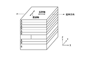
- FIG. 2 is a schematic perspective view of an example of a reflective polarizer.
- the reflective polarizer is a multilayer laminate in which layers A having birefringence and layers B having substantially no birefringence are alternately laminated.
- the total number of layers in such a multilayer stack can be 50-1000.
- the refractive index nx in the x-axis direction of the A layer is larger than the refractive index ny in the y-axis direction, and the refractive index nx in the x-axis direction and the refractive index ny in the y-axis direction of the B layer are substantially the same. is there.
- the difference in refractive index between the A layer and the B layer is large in the x-axis direction and is substantially zero in the y-axis direction.
- the x-axis direction becomes the reflection axis
- the y-axis direction becomes the transmission axis.
- the refractive index difference in the x-axis direction between the A layer and the B layer is preferably 0.2 to 0.3.
- the x-axis direction corresponds to the extending direction of the reflective polarizer in the manufacturing method described later.
- the A layer is preferably made of a material that exhibits birefringence by stretching.
- Typical examples of such materials include naphthalene dicarboxylic acid polyester (for example, polyethylene naphthalate), polycarbonate, and acrylic resin (for example, polymethyl methacrylate). Polyethylene naphthalate is preferred.
- the B layer is preferably made of a material that does not substantially exhibit birefringence even when stretched.
- a typical example of such a material is a copolyester of naphthalenedicarboxylic acid and terephthalic acid.
- the reflective polarizer transmits light having a first polarization direction (for example, p-wave) at the interface between the A layer and the B layer, and has a second polarization direction orthogonal to the first polarization direction. Reflects light (eg, s-wave). The reflected light is partially transmitted as light having the first polarization direction and partially reflected as light having the second polarization direction at the interface between the A layer and the B layer.
- the light utilization efficiency can be increased by repeating such reflection and transmission many times inside the reflective polarizer.
- the reflective polarizer may include a reflective layer R as the outermost layer on the side opposite to the polarizing plate 10, as shown in FIG.
- a reflective layer R as the outermost layer on the side opposite to the polarizing plate 10, as shown in FIG.
- the overall thickness of the reflective polarizer can be appropriately set according to the purpose, the total number of layers included in the reflective polarizer, and the like.
- the total thickness of the reflective polarizer is preferably 10 ⁇ m to 150 ⁇ m. If the overall thickness is in such a range, the distance between the light diffusion layer and the prism portion of the prism sheet can be set to a desired range, and as a result, liquid crystal that suppresses the generation of moire and has high luminance.
- a display device can be realized.
- the reflective polarizer 30 is disposed so as to transmit light having a polarization direction parallel to the transmission axis of the polarizing plate 10. That is, the reflective polarizer 30 is arranged so that its transmission axis is substantially parallel to the transmission axis direction of the polarizing plate 10. With such a configuration, light absorbed by the polarizing plate 10 can be reused, utilization efficiency can be further increased, and luminance can be improved.
- the reflective polarizer can typically be produced by a combination of coextrusion and transverse stretching. Coextrusion can be performed in any suitable manner. For example, a feed block method or a multi-manifold method may be used. For example, the material constituting the A layer and the material constituting the B layer are extruded in a feed block, and then multilayered using a multiplier. Such a multi-layer apparatus is known to those skilled in the art. Next, the obtained long multilayer laminate is typically stretched in a direction (TD) orthogonal to the transport direction. The material constituting the A layer (for example, polyethylene naphthalate) increases the refractive index only in the stretching direction due to the transverse stretching, and as a result, develops birefringence.
- TD direction orthogonal to the transport direction.
- the material constituting the A layer for example, polyethylene naphthalate
- the refractive index of the material constituting the B layer does not increase in any direction even by the transverse stretching.
- a reflective polarizer having a reflection axis in the stretching direction (TD) and a transmission axis in the transport direction (MD) can be obtained (TD corresponds to the x-axis direction in FIG. 2 and MD is the y-axis). Corresponding to the direction).
- stretching operation can be performed using arbitrary appropriate apparatuses.
- the reflective polarizer for example, the one described in JP-T-9-507308 can be used.
- a commercially available product may be used as it is, or a commercially available product may be used after secondary processing (for example, stretching).
- a commercial item 3M company brand name DBEF and 3M company brand name APF are mentioned, for example.
- the reflective polarizer 30 is bonded to the light diffusion layer 20 via any appropriate adhesive layer (for example, an adhesive layer or an adhesive layer: not shown).
- any appropriate adhesive layer for example, an adhesive layer or an adhesive layer: not shown.
- the adhesive layer can be omitted.
- the prism sheet 40 is disposed on the opposite side of the light diffusing layer 20 of the reflective polarizer 30.
- the prism sheet 40 typically includes a base material portion 41 and a prism portion 42.
- the distance between the light diffusion layer 20 and the prism part 42 can be controlled.
- the reflective polarizer 30 can function as a base material part that supports the prism part 42, the base material part 41 is not necessarily provided. In this case, the distance between the light diffusion layer 20 and the prism portion 42 can be controlled by adjusting the thickness of the reflective polarizer 30.
- the prism sheet 40 is configured so that the polarized light emitted from the light guide plate of the backlight unit remains in the prism portion 42 while maintaining its polarization state.
- the polarized light having the maximum intensity in the substantially normal direction of the liquid crystal display device is guided to the polarizing plate 10 through the reflective polarizer 30 and the light diffusion layer 20 by total internal reflection or the like.
- the “substantially normal direction” includes a direction within a predetermined angle from the normal direction, for example, a direction within a range of ⁇ 10 ° from the normal direction.
- the prism sheet 40 is bonded to the reflective polarizer 30 via any appropriate adhesive layer (for example, an adhesive layer or an adhesive layer: not shown).
- the prism sheet 40 (substantially, the prism unit 42) is a plurality of unit prisms that are convex on the side opposite to the reflective polarizer 30. 43 are arranged in parallel.
- the unit prism 43 has a columnar shape, and its longitudinal direction (ridge line direction) is substantially perpendicular to the transmission axis of the polarizing plate 10 and the transmission axis of the reflective polarizer 30.
- the expressions “substantially orthogonal” and “substantially orthogonal” include the case where the angle between the two directions is 90 ° ⁇ 10 °, preferably 90 ° ⁇ 7 °, The angle is preferably 90 ° ⁇ 5 °.
- the expressions “substantially parallel” and “substantially parallel” include the case where the angle between two directions is 0 ° ⁇ 10 °, preferably 0 ° ⁇ 7 °, more preferably 0 ° ⁇ 5 °.
- the term “orthogonal” or “parallel” may include a substantially orthogonal state or a substantially parallel state.
- the prism sheet 40 may be disposed (so-called diagonally left) so that the ridge line direction of the unit prism 43 and the transmission axis of the polarizing plate 10 and the transmission axis of the reflective polarizer 30 form a predetermined angle. .
- the range of the oblique arrangement is preferably 20 ° or less, and more preferably 15 ° or less.
- the unit prism 43 may have a triangular shape in a cross section parallel to the arrangement direction and parallel to the thickness direction, and may have another shape (for example, one or both of the inclined surfaces of the triangle have different inclination angles. It may be a shape having a plurality of flat surfaces.
- the triangular shape may be a shape that is asymmetric with respect to a straight line that passes through the vertex of the unit prism and is orthogonal to the sheet surface (for example, an unequal triangular shape), or a shape that is symmetric with respect to the straight line (for example, two An equilateral triangle).
- the apex of the unit prism may be a chamfered curved surface, or may be cut to have a flat tip at a tip, and may have a trapezoidal cross section.
- the detailed shape of the unit prism 43 can be appropriately set according to the purpose.
- the unit prism 43 the configuration described in JP-A-11-84111 can be adopted.
- the distance between the prism portion 42 and the light diffusion layer 20 is preferably 75 ⁇ m to 250 ⁇ m. By securing such a distance between the prism portion and the light diffusion layer, it is possible to satisfactorily suppress the occurrence of moire while maintaining the front contrast and luminance.
- the distance between the prism portion 42 and the light diffusion layer 20 adjusts the thickness of the reflective polarizer 30, the base material portion 41, and / or the adhesive layer between the reflective polarizer 30 and the prism sheet 40, for example. Can be controlled.
- the distance between the prism portion 42 and the light diffusion layer 20 is the distance between the flat surface of the prism portion 42 (the surface opposite to the apex of the unit prism 43) and the surface of the light diffusion layer 20 on the reflective polarizer 30 side. Say distance.
- the base material part 41 and the prism part 42 may be integrally formed by extruding a single material or the like.
- the prism portion may be formed on the film for use.
- the thickness of the base material portion is preferably 25 ⁇ m to 150 ⁇ m. With such a thickness, the distance between the light diffusion layer and the prism portion can be set to a desired range. Furthermore, such a thickness is preferable from the viewpoint of handleability and strength.
- any appropriate material can be adopted as the material constituting the base portion 41 depending on the purpose and the configuration of the prism sheet.
- the base film include (meth) acrylic resins such as cellulose triacetate (TAC) and polymethyl methacrylate (PMMA). And a film formed of polycarbonate (PC) resin.
- the film is preferably an unstretched film.
- the same material as the prism part forming material used when shaping the prism part on the base part film is used as the material.
- the prism portion forming material include epoxy acrylate-based and urethane acrylate-based reactive resins (for example, ionizing radiation curable resins).
- a polyester resin such as PC or PET, an acrylic resin such as PMMA or MS, or a light-transmitting thermoplastic resin such as cyclic polyolefin can be used.
- the base material portion 41 preferably has substantially optical isotropy.
- substantially optically isotropic means that the retardation value is small enough not to substantially affect the optical characteristics of the liquid crystal display device.
- the in-plane retardation Re of the base material portion is preferably 20 nm or less, and more preferably 10 nm or less.
- the in-plane retardation Re is an in-plane retardation value measured with light having a wavelength of 590 nm at 23 ° C.
- nx is the refractive index in the direction in which the refractive index is maximum in the plane of the optical member (that is, the slow axis direction), and ny is the direction perpendicular to the slow axis in the plane (that is, the fast phase). (Axial direction), and d is the thickness (nm) of the optical member.
- the photoelastic coefficient of the base material portion 41 is preferably ⁇ 10 ⁇ 10 ⁇ 12 m 2 / N to 10 ⁇ 10 ⁇ 12 m 2 / N, more preferably ⁇ 5 ⁇ 10 ⁇ 12 m 2 / N. It is ⁇ 5 ⁇ 10 ⁇ 12 m 2 / N, more preferably ⁇ 3 ⁇ 10 ⁇ 12 m 2 / N to 3 ⁇ 10 ⁇ 12 m 2 / N.
- the optical member 100 may further include any appropriate retardation layer at any appropriate position depending on the purpose (not shown).
- the arrangement position, the number, the birefringence (refractive index ellipsoid), etc. of the retardation layer can be appropriately selected according to the driving mode of the liquid crystal cell, desired characteristics, and the like.
- the retardation layer may also serve as a protective layer for the polarizer.
- typical examples of the retardation layer applicable to the optical member of the present invention will be described.
- the optical member when the optical member is used in an IPS mode liquid crystal display device, the optical member is a first retardation layer that satisfies nx 1 > ny 1 > nz 1 on the side opposite to the light diffusion layer 20 of the polarizing plate 10. You may have.
- the optical member may further include a second retardation layer that satisfies nz 2 > nx 2 > ny 2 on the outer side (opposite side to the polarizing plate 10) of the first retardation layer.
- the slow axis of the first retardation layer and the slow axis of the second retardation layer may be orthogonal or parallel. Considering the viewing angle and productivity, it is preferable that they are parallel.
- the in-plane retardation Re 1 of the first retardation layer is preferably 60 nm to 140 nm.
- the Nz coefficient Nz 1 of the first retardation layer is preferably 1.1 to 1.7.
- the in-plane retardation Re 2 of the second retardation layer is preferably 10 nm to 70 nm.
- the thickness direction retardation Rth 2 of the second retardation layer is preferably ⁇ 120 nm to ⁇ 40 nm.
- the in-plane retardation Re is as defined above.
- nx and ny are as defined above.
- nz is the refractive index in the thickness direction of the optical member (here, the first retardation layer or the second retardation layer). Note that the subscripts “1” and “2” represent the first retardation layer and the second retardation layer, respectively.
- the first retardation layer may be a retardation layer that satisfies nx 1 > nz 1 > ny 1 .
- “substantially equal” is intended to include the case where nx and ny are different within a range that does not have a practical effect on the overall optical characteristics of the liquid crystal display device. Therefore, the negative C plate in this embodiment includes the case of having biaxiality.
- the optical member when an optical member is used for a VA mode liquid crystal display device, the optical member may be used as a circularly polarizing plate.
- the optical member may have a first retardation layer that functions as a ⁇ / 4 plate on the side opposite to the light diffusion layer 20 of the polarizing plate 10.
- the angle formed between the absorption axis of the polarizer and the slow axis of the first retardation layer is substantially 45 degrees or substantially 135 degrees.
- the liquid crystal display device preferably has a retardation layer that functions as a ⁇ / 4 plate between the liquid crystal cell and the viewing-side polarizing plate.
- the optical member may further include a second retardation layer that satisfies nz 2 > nx 2 > ny 2 between the polarizer and the first retardation layer.
- the retardation wavelength dispersion value (Re cell [450] / Re cell [550]) of the liquid crystal cell is ⁇ cell
- the retardation wavelength dispersion value of the first retardation layer (Re 1 [450] / Re 1 [ 550]) is ⁇ 1
- ⁇ 1 / ⁇ cell is preferably 0.95 to 1.02.
- the Nz coefficient of the first retardation layer preferably satisfies the relationship 1.1 ⁇ Nz 1 ⁇ 2.4, and the Nz coefficient of the second retardation layer is ⁇ 2 ⁇ Nz 2 ⁇ It is preferable to satisfy the relationship of ⁇ 0.1.
- the optical member when an optical member is used for a VA mode liquid crystal display device, the optical member may be used as a linear polarizing plate.
- the optical member may have a first retardation layer that satisfies nx 1 > ny 1 > nz 1 on the side opposite to the light diffusion layer 20 of the polarizing plate 10.
- the in-plane retardation Re 1 of the first retardation layer is preferably 20 nm to 200 nm, more preferably 30 nm to 150 nm, and further preferably 40 nm to 100 nm.
- the thickness direction retardation Rth 1 of the first retardation layer is preferably 100 nm to 800 nm, more preferably 100 nm to 500 nm, and further preferably 150 nm to 300 nm.
- the Nz coefficient of the first retardation layer is preferably 1.3 to 8.0.
- the optical member of the present invention can be typically used as a polarizing plate (hereinafter sometimes referred to as a back-side polarizing plate) disposed on the side opposite to the viewing side of the liquid crystal display device.
- a set of polarizing plates including the back side polarizing plate and the viewing side polarizing plate can be provided. Any appropriate polarizing plate can be adopted as the viewing-side polarizing plate.
- the viewing-side polarizing plate typically has a polarizer (for example, an absorption polarizer) and a protective layer disposed on at least one side of the polarizer. As the polarizer and the protective layer, those described in the above section B can be used.
- the viewing-side polarizing plate may further include any appropriate optical functional layer (for example, a retardation layer, a hard coat layer, an antiglare layer, or an antireflection layer) depending on the purpose.
- the polarizing plate is set so that the absorption axis of the viewing side polarizing plate (the polarizer) and the absorption axis of the back side polarizing plate (the polarizer) are substantially orthogonal or parallel to each side of the liquid crystal cell. Placed in.
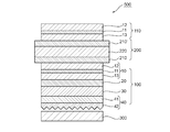
- FIG. 4 is a schematic cross-sectional view of a liquid crystal display device according to one embodiment of the present invention.
- the liquid crystal display device 500 includes the liquid crystal cell 200, the viewing side polarizing plate 110 disposed on the viewing side of the liquid crystal cell 200, and the back side polarizing plate disposed on the side opposite to the viewing side of the liquid crystal cell 200. It has the optical member 100 and the backlight unit 300 arrange
- the optical member 100 is as described in the above items A to F.
- the viewing side polarizing plate is as described in the above section G.
- the viewing-side polarizing plate 110 includes a polarizer 11, a protective layer 12 disposed on one side of the polarizer, and a protective layer 13 disposed on the other side of the polarizer 11.
- the viewing side polarizing plate 110 and the optical member (back side polarizing plate) 100 are arranged so that their absorption axes are substantially orthogonal or parallel to each other.
- the backlight unit 300 can employ any appropriate configuration.
- the backlight unit 300 may be an edge light system or a direct system.
- the backlight unit 300 includes, for example, a light source, a reflective film, and a diffusion plate (none of which are shown).
- the backlight unit 300 may further include a light guide plate and a light reflector (none of which are shown).
- the liquid crystal cell 200 includes a pair of substrates 210 and 210 'and a liquid crystal layer 220 as a display medium sandwiched between the substrates.
- one substrate 210 ′ is provided with a color filter and a black matrix
- the other substrate 210 has a switching element for controlling the electro-optical characteristics of the liquid crystal, and a gate signal is supplied to the switching element.
- a scanning line to be supplied, a signal line to supply a source signal, a pixel electrode, and a counter electrode are provided.
- the distance (cell gap) between the substrates 210 and 210 ' can be controlled by a spacer or the like.
- an alignment film made of polyimide or the like can be provided on the side of the substrates 210 and 210 ′ in contact with the liquid crystal layer 220.
- the liquid crystal layer 220 includes liquid crystal molecules aligned in a homogeneous alignment in the absence of an electric field.
- Typical examples of drive modes using such a liquid crystal layer having a three-dimensional refractive index include an in-plane switching (IPS) mode and a fringe field switching (FFS) mode.
- the IPS mode utilizes voltage-controlled birefringence (ECB: Electrically Controlled Birefringence) effect, and liquid crystal molecules aligned in a homogeneous arrangement in the absence of an electric field include, for example, a counter electrode and a pixel electrode formed of metal.
- the substrate is caused to respond with an electric field parallel to the substrate generated in step (also referred to as a transverse electric field). More specifically, for example, Techno Times Publishing “Monthly Display July” p. 83-p. 88 (1997 edition) and “Liquid Crystal vol. 2 No.
- the IPS mode includes a super-in-plane switching (S-IPS) mode and an advanced super-in-plane switching (AS-IPS) mode using a V-shaped electrode or a zigzag electrode.
- the FFS mode utilizes a voltage-controlled birefringence effect, and a substrate in which liquid crystal molecules aligned in a homogeneous arrangement in the absence of an electric field are generated by, for example, a counter electrode and a pixel electrode formed of a transparent conductor It responds with an electric field parallel to (also called a transverse electric field).
- the lateral electric field in the FFS mode is also referred to as a fringe electric field.
- This fringe electric field can be generated by setting the interval between the counter electrode formed of a transparent conductor and the pixel electrode to be narrower than the cell gap. More specifically, SID (Society for Information Display) 2001 Digest, p. 484-p. As described in 487 and Japanese Patent Application Laid-Open No.
- the alignment direction of the liquid crystal cell when no electric field is applied is aligned with the absorption axis of the polarizer on one side.
- the display is completely black with no electric field.
- the transmittance according to the rotation angle can be obtained by rotating the liquid crystal molecules while keeping them parallel to the substrate.
- the FFS mode includes an advanced fringe field switching (A-FFS) mode and an ultra fringe field switching (U-FFS) mode employing a V-shaped electrode or a zigzag electrode.
- a driving mode for example, IPS mode or FFS mode
- liquid crystal molecules aligned in a homogeneous arrangement in the absence of the electric field has no oblique gradation inversion and has a wide oblique viewing angle, and thus is used in the present invention. Even if a surface light source oriented in the front direction is used, there is an advantage that visibility from an oblique direction is excellent.
- the liquid crystal layer 220 includes liquid crystal molecules aligned in a homeotropic alignment in the absence of an electric field.
- An example of a drive mode using liquid crystal molecules aligned in a homeotropic alignment in the absence of an electric field is a vertical alignment (VA) mode.
- VA mode includes a multi-domain VA (MVA) mode.
- FIG. 5 is a schematic cross-sectional view for explaining the alignment state of the liquid crystal molecules in the VA mode.
- the liquid crystal molecules in the VA mode are aligned substantially perpendicular (normal direction) to the surfaces of the substrates 210 and 210 'when no voltage is applied.
- substantially perpendicular includes the case where the alignment vector of the liquid crystal molecules is tilted with respect to the normal direction, that is, the case where the liquid crystal molecules have a tilt angle.
- the tilt angle (angle from the normal line) is preferably 10 ° or less, more preferably 5 ° or less, and particularly preferably 1 ° or less. By having a tilt angle in such a range, the contrast can be excellent.
- substantially vertical alignment can be realized, for example, by arranging a nematic liquid crystal having negative dielectric anisotropy between substrates on which a vertical alignment film is formed.
- the linearly polarized light that has entered the liquid crystal layer 220 through the optical member 100 travels along the major axis direction of the liquid crystal molecules that are substantially vertically aligned. Since substantially no birefringence occurs in the major axis direction of the liquid crystal molecules, the incident light travels without changing the polarization direction and is absorbed by the viewing side polarizing plate 110 having a transmission axis orthogonal to the optical member 100. This provides a dark display when no voltage is applied (normally black mode).
- the major axis of the liquid crystal molecules is aligned parallel to the substrate surface.
- the liquid crystal molecules in this state exhibit birefringence with respect to linearly polarized light that has passed through the optical member 100 and entered the liquid crystal layer, and the polarization state of the incident light changes according to the inclination of the liquid crystal molecules.
- the light passing through the liquid crystal layer 220 when a predetermined maximum voltage is applied becomes, for example, linearly polarized light whose polarization direction is rotated by 90 °, and thus is transmitted through the viewing-side polarizing plate 110 to obtain a bright display.
- the display can be returned to the dark state by the orientation regulating force.
- gradation display is possible by changing the applied voltage to control the inclination of the liquid crystal molecules to change the transmitted light intensity from the viewing side polarizing plate 110.
- Example 1> (Creation of first retardation layer film) Using a tenter stretching machine, a commercially available polymer film (trade name “Zeonor film ZF14-130 (thickness: 60 ⁇ m, glass transition temperature: 136 ° C.)” manufactured by Optes, Inc.) mainly composed of a cyclic polyolefin-based polymer is used. At a temperature of 158 ° C., the fixed end was uniaxially stretched in the width direction so that the film width was 3.0 times the original film width (lateral stretching step). The obtained film was a negative biaxial plate (three-dimensional refractive index: nx>ny> nz) having a fast axis in the transport direction. The negative biaxial plate had an in-plane retardation of 118 nm and an Nz coefficient of 1.16.
- a commercially available polymer film (trade name “Zeonor film ZF14-130 (thickness: 60 ⁇ m, glass transition temperature: 136 ° C.)
- Styrene-maleic anhydride copolymer (manufactured by Nova Chemical Japan Co., Ltd., product name “Dylark D232”) is extruded at 270 ° C. using a single screw extruder and a T die, and melted in a sheet form. The resin was cooled with a cooling drum to obtain a film having a thickness of 100 ⁇ m. This film was uniaxially stretched in the transport direction at a temperature of 130 ° C. and a stretch ratio of 1.5 times using a roll stretching machine to obtain a retardation film having a fast axis in the transport direction (longitudinal stretching). Process).
- the obtained film was uniaxially stretched at a fixed end in the width direction so that the film width was 1.2 times the film width after the longitudinal stretching at a temperature of 135 ° C., and the thickness was 50 ⁇ m.
- a biaxially stretched film was obtained (transverse stretching step).
- the obtained film was a positive biaxial plate (three-dimensional refractive index: nz>nx> ny) having a fast axis in the transport direction.
- the positive biaxial plate had an in-plane retardation of 20 nm and a thickness retardation Rth of ⁇ 80 nm.
- the stretched film was further stretched up to 6 times based on the original length in the transport direction while being immersed in an aqueous solution having a boric acid concentration of 4% by weight and a potassium iodide concentration of 5% by weight, and dried at 70 ° C. for 2 minutes. By doing so, a polarizer was obtained.
- an alumina colloid-containing adhesive was applied to one side of a triacetyl cellulose (TAC) film (manufactured by Konica Minolta, product name “KC4UW”, thickness: 40 ⁇ m), and this was applied to one side of the polarizer obtained above. They were laminated by roll-to-roll so that the conveying directions of both were parallel.
- TAC triacetyl cellulose
- the alumina colloid-containing adhesive is methylol based on 100 parts by weight of polyvinyl alcohol resin having an acetoacetyl group (average polymerization degree 1200, saponification degree 98.5% mol%, acetoacetylation degree 5 mol%). Melting 50 parts by weight of melamine in pure water to prepare an aqueous solution having a solid content concentration of 3.7% by weight. With respect to 100 parts by weight of this aqueous solution, an alumina colloid having a positive charge (average particle diameter of 15 nm) It was prepared by adding 18 parts by weight of an aqueous solution containing 10% by weight.
- the first retardation layer film coated with the alumina colloid-containing adhesive is laminated with a roll-to-roll so that these transport directions are parallel, Thereafter, it was dried at 55 ° C. for 6 minutes.
- a second retardation layer film is placed on a roll so that the transport directions thereof are parallel via an acrylic adhesive (thickness: 5 ⁇ m).
- a PET film (thickness: 100 ⁇ m) was used as the base film. As shown in FIG. 1 and FIG. 3, a predetermined mold in which the PET film is arranged is filled with an ultraviolet curable urethane acrylate resin as a prism material, and the prism material is cured by irradiating ultraviolet rays. A prism sheet was prepared. The in-plane retardation Re of the base material portion was 0 nm. The unit prism was a triangular prism, and the cross-sectional shape parallel to the arrangement direction and parallel to the thickness direction was an unequal triangular shape.
- a polarizing plate with a retardation layer and a reflective polarizer obtained above (a reflective polarizer taken out of a backlight member by decomposing a 40-inch TV manufactured by SHARP (product name: AQUAS, product number: LC40-Z5)) Were bonded through a light diffusion adhesive having a haze value of 80%.
- the light diffusing adhesive was prepared by blending 25.9 parts of light diffusing fine particles (product name “Tospearl 145”, particle size 4.5 ⁇ m, manufactured by Momentive Performance) into 100 parts of the acrylic adhesive.
- This reflective polarizer-integrated polarizing plate and the inverted prism sheet obtained above are bonded together via an acrylic pressure-sensitive adhesive (23 ⁇ m), whereby a polarizing plate / light diffusion layer (light diffusion adhesive as shown in FIG. 1).
- An optical member having a composition of (agent layer) / reflection type polarizer / prism sheet was obtained.
- the ridgeline direction of the unit prism of the prism sheet and the transmission axis of the polarizing plate were orthogonal to each other, and the transmission axis of the polarizing plate and the transmission axis of the reflective polarizer were integrated.
- the distance between the light diffusion layer and the prism portion was 243 ⁇ m.
- a liquid crystal panel was taken out from the IPS mode liquid crystal display device (manufactured by Apple, trade name “iPad2”), an optical member such as a polarizing plate was removed from the liquid crystal panel, and a liquid crystal cell was taken out.
- the liquid crystal cell was used by washing both surfaces (outside of each glass substrate).
- a commercially available polarizing plate manufactured by Nitto Denko Corporation, product name “CVT1764FCUHC” was attached to the upper side (viewing side) of the liquid crystal cell.
- a ⁇ / 4 plate (trade name “UTZ-film # 140”, manufactured by Kaneka Corporation) on the polarizing plate is delayed.
- the phase axis was pasted so as to form an angle of 45 ° with the absorption axis of the polarizing plate.
- the optical member obtained above was attached to the lower side (back side) of the liquid crystal cell via an acrylic adhesive as a lower (back side) polarizing plate to obtain a liquid crystal display panel.
- the polarizing plates were pasted so that the transmission axes of the polarizing plates were orthogonal to each other.
- Example 2 In the same manner as in Example 1, except that the thickness of the PET film for the base material portion of the prism sheet was 75 ⁇ m, the thickness of the reflective polarizer was 35 ⁇ m, and the distance between the light diffusion layer and the prism portion was 133 ⁇ m. A display device was produced. The obtained liquid crystal display device was subjected to the evaluations (1) to (4) above. The results are shown in Table 1.
- the substrate film for the prism sheet is an acrylic film having a thickness of 30 ⁇ m, the thickness of the adhesive layer between the reflective polarizer and the prism sheet is 12 ⁇ m, and the distance between the light diffusion layer and the prism part is 77 ⁇ m.
- a liquid crystal display device was produced in the same manner as in Example 2 except for the above. The obtained liquid crystal display device was subjected to the evaluations (1) to (4) above. The results are shown in Table 1.
- Example 4 A liquid crystal display device was produced in the same manner as in Example 2 except that the haze value of the light diffusion adhesive was 85%. The obtained liquid crystal display device was subjected to the evaluations (1) to (4) above. The results are shown in Table 1.
- Example 5 A liquid crystal display device was produced in the same manner as in Example 2 except that the haze value of the light diffusion adhesive was 60%. The obtained liquid crystal display device was subjected to the evaluations (1) to (4) above. The results are shown in Table 1.
- Example 1 The polarizing plate with a retardation layer obtained in Example 1 and the reflective polarizer were bonded together via an acrylic pressure-sensitive adhesive. The thus obtained reflective polarizer-integrated polarizing plate and the inverted prism sheet obtained in Example 2 were bonded together with the light diffusion adhesive used in Example 1 to obtain a polarizing plate / reflective polarizer. An optical member having a structure of / light diffusion layer (light diffusion pressure-sensitive adhesive layer) / prism sheet was obtained. The obtained liquid crystal display device was subjected to the evaluations (1) to (4) above. The results are shown in Table 1.
- Comparative Example 4 The same as Comparative Example 3 except that the reflective polarizer was not used, that is, the optical member having the configuration of a light diffusion layer (light diffusion adhesive layer) / polarizing plate / prism sheet was used as the back side polarizing plate. Thus, a liquid crystal display device was produced. The obtained liquid crystal display device was subjected to the evaluations (1) to (4) above. The results are shown in Table 1.
- Comparative Example 5 The same as Comparative Example 1 except that the reflective polarizer was not used, that is, an optical member having a configuration of polarizing plate / light diffusion layer (light diffusion pressure-sensitive adhesive layer) / prism sheet was used as the back side polarizing plate. Thus, a liquid crystal display device was produced. The obtained liquid crystal display device was subjected to the evaluations (1) to (4) above. The results are shown in Table 1.
- the liquid crystal display device using the optical member of the example of the present invention as the back-side polarizing plate was suppressed in moire and good in both front luminance and front contrast. Furthermore, it was confirmed that the liquid crystal display devices of the examples were excellent in mechanical strength without causing appearance defects in the display even after the vibration test. On the other hand, in the comparative example, a liquid crystal display device satisfying all of the moire characteristics, luminance, and front contrast could not be obtained. More specifically, the brightness of the liquid crystal display device using the optical member of Comparative Example 1 having a light diffusion layer between the reflective polarizer and the prism sheet was lowered.
- Comparative Example 1 and Comparative Example 2 when the haze value of the light diffusion layer is decreased, the luminance is improved, but the moire becomes remarkable.
- the front contrast was lowered.
- Comparative Example 3 and Comparative Example 4 the luminance was reduced when the reflective polarizer was omitted.
- the optical member of the present invention can be suitably used as a back side polarizing plate of a liquid crystal display device.
- Liquid crystal display devices using such optical members are portable devices such as personal digital assistants (PDAs), mobile phones, watches, digital cameras, and portable game machines, OA devices such as personal computer monitors, notebook computers, and copy machines, and video.
- Household electrical equipment such as cameras, LCD TVs, and microwave ovens, back monitors, car navigation system monitors, car audio equipment and other in-vehicle equipment, display equipment such as commercial store information monitors, security equipment such as monitoring monitors, It can be used for various applications such as nursing care and medical equipment such as nursing monitors and medical monitors.
Landscapes
- Physics & Mathematics (AREA)
- General Physics & Mathematics (AREA)
- Optics & Photonics (AREA)
- Nonlinear Science (AREA)
- Mathematical Physics (AREA)
- Chemical & Material Sciences (AREA)
- Crystallography & Structural Chemistry (AREA)
- Liquid Crystal (AREA)
- Polarising Elements (AREA)
- Optical Elements Other Than Lenses (AREA)
Priority Applications (4)
| Application Number | Priority Date | Filing Date | Title |
|---|---|---|---|
| CN201380019384.5A CN104220904B (zh) | 2012-04-13 | 2013-04-10 | 光学构件、偏振板组及液晶显示设备 |
| KR1020147028413A KR20140132409A (ko) | 2012-04-13 | 2013-04-10 | 광학 부재, 편광판 세트 및 액정 표시 장치 |
| KR1020167016603A KR20160079902A (ko) | 2012-04-13 | 2013-04-10 | 광학 부재, 편광판 세트 및 액정 표시 장치 |
| US14/391,442 US10001669B2 (en) | 2012-04-13 | 2013-04-10 | Optical member, polarizing plate set and liquid crystal display apparatus |
Applications Claiming Priority (2)
| Application Number | Priority Date | Filing Date | Title |
|---|---|---|---|
| JP2012091742 | 2012-04-13 | ||
| JP2012-091742 | 2012-04-13 |
Publications (1)
| Publication Number | Publication Date |
|---|---|
| WO2013154125A1 true WO2013154125A1 (ja) | 2013-10-17 |
Family
ID=49327685
Family Applications (1)
| Application Number | Title | Priority Date | Filing Date |
|---|---|---|---|
| PCT/JP2013/060785 WO2013154125A1 (ja) | 2012-04-13 | 2013-04-10 | 光学部材、偏光板のセットおよび液晶表示装置 |
Country Status (6)
Cited By (4)
| Publication number | Priority date | Publication date | Assignee | Title |
|---|---|---|---|---|
| WO2014188869A1 (ja) * | 2013-05-20 | 2014-11-27 | 日東電工株式会社 | 光学部材、偏光板のセットおよび液晶表示装置 |
| EP2921902A4 (en) * | 2013-10-31 | 2016-07-13 | Nitto Denko Corp | LIQUID CRYSTAL PANEL AND POLARIZATOR LAMINATE USED IN THIS LIQUID CRYSTAL PANEL |
| CN105829947A (zh) * | 2013-12-18 | 2016-08-03 | 奥特司科技株式会社 | 平视显示器装置用液晶显示装置以及平视显示器装置 |
| US10942310B2 (en) | 2017-04-27 | 2021-03-09 | Panasonic Intellectual Property Management Co., Ltd. | On-board display device |
Families Citing this family (29)
| Publication number | Priority date | Publication date | Assignee | Title |
|---|---|---|---|---|
| ES2897531T3 (es) | 2010-10-25 | 2022-03-01 | Accuri Cytometers Inc | Sistemas e interfaz de usuario para la recopilación de un conjunto de datos en un citómetro de flujo |
| US10185068B2 (en) * | 2013-09-06 | 2019-01-22 | 3M Innovative Properties Company | Multilayer reflective polarizer |
| JP6843491B2 (ja) * | 2014-02-17 | 2021-03-17 | 大日本印刷株式会社 | 積層体、積層体の製造方法、画像表示装置、画像表示装置の製造方法及び偏光板の光透過率改善方法 |
| JP2015200866A (ja) * | 2014-03-31 | 2015-11-12 | 日東電工株式会社 | 光学部材、偏光板のセットおよび液晶表示装置 |
| JP6276842B2 (ja) * | 2014-03-31 | 2018-02-07 | 積水化成品工業株式会社 | 光学フィルム及びその用途 |
| KR101731676B1 (ko) * | 2014-07-23 | 2017-05-02 | 삼성에스디아이 주식회사 | 편광판 및 이를 포함하는 광학표시장치 |
| KR102084299B1 (ko) * | 2014-12-30 | 2020-03-03 | 쓰리엠 이노베이티브 프로퍼티즈 컴파니 | 반사 편광기 및 보상 필름을 포함하는 광학 적층물 |
| TW201706629A (zh) * | 2015-04-24 | 2017-02-16 | 3M新設資產公司 | 光學膜 |
| JP6502282B2 (ja) * | 2015-04-24 | 2019-04-17 | 富士フイルム株式会社 | 検知方法および検知システム |
| US10408989B2 (en) * | 2015-04-29 | 2019-09-10 | Samsung Sdi Co., Ltd. | Optical film for improving contrast ratio, polarizing plate including same, and liquid crystal display device including same |
| JP2017049326A (ja) | 2015-08-31 | 2017-03-09 | 株式会社ジャパンディスプレイ | 表示装置 |
| JP2017062609A (ja) * | 2015-09-24 | 2017-03-30 | 日東電工株式会社 | 透明導電性フィルム、及びそれを含むタッチパネル |
| KR20170064039A (ko) | 2015-11-30 | 2017-06-09 | 엘지디스플레이 주식회사 | 광학 필름 및 이를 포함하는 액정 표시장치 |
| JP6809824B2 (ja) | 2016-07-04 | 2021-01-06 | 日東電工株式会社 | 光学積層体の製造方法、および光学積層体中間体 |
| JP2018036586A (ja) * | 2016-09-02 | 2018-03-08 | 日東電工株式会社 | 光学部材 |
| JP7027035B2 (ja) * | 2016-11-15 | 2022-03-01 | 日東電工株式会社 | 光通信装置及び偏光板のセット |
| US10824011B2 (en) * | 2017-01-04 | 2020-11-03 | Samsung Electronics Co., Ltd. | Photoluminescent polarizers having metal film with surface plasmon coupling and electronic devices including the same |
| US10527878B2 (en) * | 2017-09-13 | 2020-01-07 | Int Tech Co., Ltd. | Display panel and method for manufacturing the same |
| JP6873269B2 (ja) * | 2017-11-08 | 2021-05-19 | 富士フイルム株式会社 | 光学積層フィルムおよび有機エレクトロルミネセンス表示装置 |
| JP6993187B2 (ja) * | 2017-11-16 | 2022-01-13 | 日東電工株式会社 | 光学部材 |
| JP7043521B2 (ja) * | 2017-12-28 | 2022-03-29 | 日東電工株式会社 | 偏光板のセットおよび液晶表示パネル |
| CN110221375B (zh) * | 2018-03-02 | 2022-08-02 | 住友化学株式会社 | 层叠膜 |
| CN108761579A (zh) * | 2018-06-15 | 2018-11-06 | 阜阳昂科丰光电科技有限公司 | 一种聚合物多层光学膜制备方法 |
| JP7193270B2 (ja) * | 2018-08-22 | 2022-12-20 | スタンレー電気株式会社 | 車両用灯具の制御装置、車両用灯具の制御方法、車両用灯具システム |
| KR101965333B1 (ko) * | 2018-09-14 | 2019-04-03 | 엘지디스플레이 주식회사 | 광학 필름 및 이를 포함하는 액정 표시장치 |
| US11288486B2 (en) * | 2019-06-12 | 2022-03-29 | Lms Co., Ltd. | Fingerprint recognition optical film, and backlight unit and liquid crystal display device comprising the film optical |
| US20230074182A1 (en) * | 2020-02-07 | 2023-03-09 | 3M Innovative Properties Company | Reflective polarizer and display system |
| CN114927628A (zh) * | 2022-05-27 | 2022-08-19 | 武汉华星光电半导体显示技术有限公司 | 显示面板及显示装置 |
| CN115840310A (zh) * | 2022-11-25 | 2023-03-24 | Tcl华星光电技术有限公司 | 一种光学膜片组件、背光模组和显示装置 |
Citations (3)
| Publication number | Priority date | Publication date | Assignee | Title |
|---|---|---|---|---|
| JP2004054034A (ja) * | 2002-07-22 | 2004-02-19 | Seiko Epson Corp | 液晶表示装置及び電子機器 |
| JP2006138975A (ja) * | 2004-11-11 | 2006-06-01 | Nec Lcd Technologies Ltd | バックライト及び液晶表示装置 |
| JP2007502010A (ja) * | 2003-05-16 | 2007-02-01 | スリーエム イノベイティブ プロパティズ カンパニー | 表面構造化光学フィルムの積み重ね方法 |
Family Cites Families (20)
| Publication number | Priority date | Publication date | Assignee | Title |
|---|---|---|---|---|
| JPH11295714A (ja) | 1998-04-08 | 1999-10-29 | Enplas Corp | 液晶表示パネル、液晶表示装置及びシート部材 |
| JP2001051268A (ja) * | 1999-08-17 | 2001-02-23 | Nitto Denko Corp | 液晶表示装置 |
| JP2001166302A (ja) | 1999-12-09 | 2001-06-22 | Enplas Corp | 液晶表示装置、面光源装置及び光制御シート |
| JP2003215563A (ja) * | 2002-01-25 | 2003-07-30 | Nitto Denko Corp | 光学フィルム及びこれを用いた液晶表示装置 |
| KR100962650B1 (ko) * | 2003-03-05 | 2010-06-11 | 삼성전자주식회사 | 광학시트 및 이를 사용하는 액정표시장치 |
| KR20050090203A (ko) | 2004-03-08 | 2005-09-13 | 삼성전자주식회사 | 광학 부재, 이를 갖는 백라이트 어셈블리 및 이를 갖는표시장치 |
| JP2006099975A (ja) * | 2004-09-28 | 2006-04-13 | Seiko Epson Corp | 電気光学装置および電子機器 |
| JP4158824B2 (ja) * | 2005-09-15 | 2008-10-01 | ソニー株式会社 | 光透過フィルム、光透過フィルムの製造方法及び液晶表示装置 |
| JP2008139819A (ja) * | 2006-11-07 | 2008-06-19 | Mitsubishi Rayon Co Ltd | 液晶表示装置、面光源装置及びプリズムシート、並びにこれらの製造方法 |
| JP2008261961A (ja) | 2007-04-10 | 2008-10-30 | Sony Corp | 光学素子包装体、バックライトおよび液晶表示装置 |
| JP5393048B2 (ja) | 2007-06-29 | 2014-01-22 | 日東電工株式会社 | 液晶表示装置および積層偏光板ならびに偏光光源装置 |
| JP2009080945A (ja) * | 2007-09-25 | 2009-04-16 | Toshiba Matsushita Display Technology Co Ltd | 両面発光面光源装置及びこれを用いた液晶表示装置 |
| EP2212395B1 (en) * | 2007-11-08 | 2018-06-13 | 3M Innovative Properties Company | Optical adhesive with diffusive properties |
| JP4905438B2 (ja) * | 2008-11-18 | 2012-03-28 | カシオ計算機株式会社 | 液晶表示装置 |
| JP5084769B2 (ja) | 2009-03-13 | 2012-11-28 | 株式会社ジャパンディスプレイイースト | 液晶表示装置 |
| WO2010137376A1 (ja) * | 2009-05-29 | 2010-12-02 | シャープ株式会社 | 液晶表示装置 |
| JP2011102848A (ja) * | 2009-11-10 | 2011-05-26 | Toppan Printing Co Ltd | 光学シート、バックライト・ユニット及びディスプレイ装置 |
| JP5529665B2 (ja) * | 2009-11-16 | 2014-06-25 | 住友化学株式会社 | 偏光板、ならびにこれを用いた液晶パネルおよび液晶表示装置 |
| JP2012032751A (ja) | 2010-07-01 | 2012-02-16 | Sumitomo Chemical Co Ltd | 液晶表示装置 |
| KR102138075B1 (ko) | 2014-01-09 | 2020-07-27 | 삼성전자주식회사 | 미디어 데이터를 전송하기 위한 가변 크기 데이터 패킷을 송수신하는 방법 및 장치 |
-
2013
- 2013-04-09 JP JP2013081050A patent/JP5812444B2/ja active Active
- 2013-04-10 KR KR1020167016603A patent/KR20160079902A/ko not_active Ceased
- 2013-04-10 KR KR1020147028413A patent/KR20140132409A/ko not_active Ceased
- 2013-04-10 WO PCT/JP2013/060785 patent/WO2013154125A1/ja active Application Filing
- 2013-04-10 US US14/391,442 patent/US10001669B2/en not_active Expired - Fee Related
- 2013-04-10 CN CN201380019384.5A patent/CN104220904B/zh active Active
- 2013-04-12 TW TW102113157A patent/TWI550319B/zh active
-
2015
- 2015-05-25 JP JP2015105200A patent/JP5913689B2/ja active Active
Patent Citations (3)
| Publication number | Priority date | Publication date | Assignee | Title |
|---|---|---|---|---|
| JP2004054034A (ja) * | 2002-07-22 | 2004-02-19 | Seiko Epson Corp | 液晶表示装置及び電子機器 |
| JP2007502010A (ja) * | 2003-05-16 | 2007-02-01 | スリーエム イノベイティブ プロパティズ カンパニー | 表面構造化光学フィルムの積み重ね方法 |
| JP2006138975A (ja) * | 2004-11-11 | 2006-06-01 | Nec Lcd Technologies Ltd | バックライト及び液晶表示装置 |
Cited By (8)
| Publication number | Priority date | Publication date | Assignee | Title |
|---|---|---|---|---|
| WO2014188869A1 (ja) * | 2013-05-20 | 2014-11-27 | 日東電工株式会社 | 光学部材、偏光板のセットおよび液晶表示装置 |
| US10175403B2 (en) | 2013-05-20 | 2019-01-08 | Nitto Denko Corporation | Optical member, polarizing plate set, and liquid crystal display apparatus |
| EP2921902A4 (en) * | 2013-10-31 | 2016-07-13 | Nitto Denko Corp | LIQUID CRYSTAL PANEL AND POLARIZATOR LAMINATE USED IN THIS LIQUID CRYSTAL PANEL |
| US9927656B2 (en) | 2013-10-31 | 2018-03-27 | Nitto Denko Corporation | Liquid crystal panel and polarizing laminate for use in the liquid crystal panel |
| CN105829947A (zh) * | 2013-12-18 | 2016-08-03 | 奥特司科技株式会社 | 平视显示器装置用液晶显示装置以及平视显示器装置 |
| EP3086169A4 (en) * | 2013-12-18 | 2017-08-16 | Ortus Technology Co., Ltd. | Liquid-crystal display for heads-up display, and heads-up display |
| US10067343B2 (en) | 2013-12-18 | 2018-09-04 | Ortus Technology Co., Ltd. | Liquid crystal display device for head-up display device, and head-up display device |
| US10942310B2 (en) | 2017-04-27 | 2021-03-09 | Panasonic Intellectual Property Management Co., Ltd. | On-board display device |
Also Published As
| Publication number | Publication date |
|---|---|
| CN104220904A (zh) | 2014-12-17 |
| US20150109561A1 (en) | 2015-04-23 |
| JP2013235259A (ja) | 2013-11-21 |
| JP2015180951A (ja) | 2015-10-15 |
| TW201350989A (zh) | 2013-12-16 |
| TWI550319B (zh) | 2016-09-21 |
| JP5812444B2 (ja) | 2015-11-11 |
| CN104220904B (zh) | 2018-05-29 |
| US10001669B2 (en) | 2018-06-19 |
| JP5913689B2 (ja) | 2016-04-27 |
| KR20160079902A (ko) | 2016-07-06 |
| KR20140132409A (ko) | 2014-11-17 |
Similar Documents
| Publication | Publication Date | Title |
|---|---|---|
| JP5913689B2 (ja) | 光学部材、偏光板のセットおよび液晶表示装置 | |
| JP6310645B2 (ja) | 光学部材、偏光板のセットおよび液晶表示装置 | |
| JP6202828B2 (ja) | 液晶表示装置 | |
| WO2014042110A1 (ja) | 光学部材、偏光板のセットおよび液晶表示装置 | |
| JP6377887B2 (ja) | 液晶表示装置 | |
| US20150277012A1 (en) | Optical member, polarizing plate set, and liquid crystal display apparatus | |
| JP6870907B2 (ja) | 光学部材、偏光板のセットおよび液晶表示装置 | |
| WO2012005050A1 (ja) | 液晶表示装置 | |
| JP2018036586A (ja) | 光学部材 | |
| WO2010001920A1 (ja) | 液晶表示装置 | |
| KR102315475B1 (ko) | 광학 부재 | |
| JP2012145735A (ja) | 液晶パネルおよび液晶表示装置 |
Legal Events
| Date | Code | Title | Description |
|---|---|---|---|
| 121 | Ep: the epo has been informed by wipo that ep was designated in this application |
Ref document number: 13776008 Country of ref document: EP Kind code of ref document: A1 |
|
| ENP | Entry into the national phase |
Ref document number: 20147028413 Country of ref document: KR Kind code of ref document: A |
|
| WWE | Wipo information: entry into national phase |
Ref document number: 14391442 Country of ref document: US |
|
| NENP | Non-entry into the national phase |
Ref country code: DE |
|
| 122 | Ep: pct application non-entry in european phase |
Ref document number: 13776008 Country of ref document: EP Kind code of ref document: A1 |