WO2013153840A1 - 2サイクルガスエンジン - Google Patents
2サイクルガスエンジン Download PDFInfo
- Publication number
- WO2013153840A1 WO2013153840A1 PCT/JP2013/052212 JP2013052212W WO2013153840A1 WO 2013153840 A1 WO2013153840 A1 WO 2013153840A1 JP 2013052212 W JP2013052212 W JP 2013052212W WO 2013153840 A1 WO2013153840 A1 WO 2013153840A1
- Authority
- WO
- WIPO (PCT)
- Prior art keywords
- fuel gas
- piston
- combustion chamber
- gas injection
- dead center
- Prior art date
- Legal status (The legal status is an assumption and is not a legal conclusion. Google has not performed a legal analysis and makes no representation as to the accuracy of the status listed.)
- Ceased
Links
Images


Classifications
-
- F—MECHANICAL ENGINEERING; LIGHTING; HEATING; WEAPONS; BLASTING
- F02—COMBUSTION ENGINES; HOT-GAS OR COMBUSTION-PRODUCT ENGINE PLANTS
- F02B—INTERNAL-COMBUSTION PISTON ENGINES; COMBUSTION ENGINES IN GENERAL
- F02B75/00—Other engines
- F02B75/02—Engines characterised by their cycles, e.g. six-stroke
-
- F—MECHANICAL ENGINEERING; LIGHTING; HEATING; WEAPONS; BLASTING
- F02—COMBUSTION ENGINES; HOT-GAS OR COMBUSTION-PRODUCT ENGINE PLANTS
- F02B—INTERNAL-COMBUSTION PISTON ENGINES; COMBUSTION ENGINES IN GENERAL
- F02B25/00—Engines characterised by using fresh charge for scavenging cylinders
- F02B25/02—Engines characterised by using fresh charge for scavenging cylinders using unidirectional scavenging
- F02B25/04—Engines having ports both in cylinder head and in cylinder wall near bottom of piston stroke
-
- F—MECHANICAL ENGINEERING; LIGHTING; HEATING; WEAPONS; BLASTING
- F02—COMBUSTION ENGINES; HOT-GAS OR COMBUSTION-PRODUCT ENGINE PLANTS
- F02B—INTERNAL-COMBUSTION PISTON ENGINES; COMBUSTION ENGINES IN GENERAL
- F02B43/00—Engines characterised by operating on gaseous fuels; Plants including such engines
- F02B43/02—Engines characterised by means for increasing operating efficiency
- F02B43/04—Engines characterised by means for increasing operating efficiency for improving efficiency of combustion
-
- F—MECHANICAL ENGINEERING; LIGHTING; HEATING; WEAPONS; BLASTING
- F01—MACHINES OR ENGINES IN GENERAL; ENGINE PLANTS IN GENERAL; STEAM ENGINES
- F01M—LUBRICATING OF MACHINES OR ENGINES IN GENERAL; LUBRICATING INTERNAL COMBUSTION ENGINES; CRANKCASE VENTILATING
- F01M1/00—Pressure lubrication
- F01M1/16—Controlling lubricant pressure or quantity
-
- F—MECHANICAL ENGINEERING; LIGHTING; HEATING; WEAPONS; BLASTING
- F02—COMBUSTION ENGINES; HOT-GAS OR COMBUSTION-PRODUCT ENGINE PLANTS
- F02B—INTERNAL-COMBUSTION PISTON ENGINES; COMBUSTION ENGINES IN GENERAL
- F02B23/00—Other engines characterised by special shape or construction of combustion chambers to improve operation
- F02B23/02—Other engines characterised by special shape or construction of combustion chambers to improve operation with compression ignition
- F02B23/06—Other engines characterised by special shape or construction of combustion chambers to improve operation with compression ignition the combustion space being arranged in working piston
- F02B23/0603—Other engines characterised by special shape or construction of combustion chambers to improve operation with compression ignition the combustion space being arranged in working piston at least part of the interior volume or the wall of the combustion space being made of material different from the surrounding piston part, e.g. combustion space formed within a ceramic part fixed to a metal piston head
-
- F—MECHANICAL ENGINEERING; LIGHTING; HEATING; WEAPONS; BLASTING
- F02—COMBUSTION ENGINES; HOT-GAS OR COMBUSTION-PRODUCT ENGINE PLANTS
- F02B—INTERNAL-COMBUSTION PISTON ENGINES; COMBUSTION ENGINES IN GENERAL
- F02B25/00—Engines characterised by using fresh charge for scavenging cylinders
- F02B25/02—Engines characterised by using fresh charge for scavenging cylinders using unidirectional scavenging
- F02B25/04—Engines having ports both in cylinder head and in cylinder wall near bottom of piston stroke
- F02B25/06—Engines having ports both in cylinder head and in cylinder wall near bottom of piston stroke the cylinder-head ports being controlled by working pistons, e.g. by sleeve-shaped extensions thereof
-
- F—MECHANICAL ENGINEERING; LIGHTING; HEATING; WEAPONS; BLASTING
- F02—COMBUSTION ENGINES; HOT-GAS OR COMBUSTION-PRODUCT ENGINE PLANTS
- F02D—CONTROLLING COMBUSTION ENGINES
- F02D19/00—Controlling engines characterised by their use of non-liquid fuels, pluralities of fuels, or non-fuel substances added to the combustible mixtures
- F02D19/06—Controlling engines characterised by their use of non-liquid fuels, pluralities of fuels, or non-fuel substances added to the combustible mixtures peculiar to engines working with pluralities of fuels, e.g. alternatively with light and heavy fuel oil, other than engines indifferent to the fuel consumed
- F02D19/0663—Details on the fuel supply system, e.g. tanks, valves, pipes, pumps, rails, injectors or mixers
- F02D19/0686—Injectors
- F02D19/0694—Injectors operating with a plurality of fuels
-
- F—MECHANICAL ENGINEERING; LIGHTING; HEATING; WEAPONS; BLASTING
- F02—COMBUSTION ENGINES; HOT-GAS OR COMBUSTION-PRODUCT ENGINE PLANTS
- F02D—CONTROLLING COMBUSTION ENGINES
- F02D19/00—Controlling engines characterised by their use of non-liquid fuels, pluralities of fuels, or non-fuel substances added to the combustible mixtures
- F02D19/06—Controlling engines characterised by their use of non-liquid fuels, pluralities of fuels, or non-fuel substances added to the combustible mixtures peculiar to engines working with pluralities of fuels, e.g. alternatively with light and heavy fuel oil, other than engines indifferent to the fuel consumed
- F02D19/08—Controlling engines characterised by their use of non-liquid fuels, pluralities of fuels, or non-fuel substances added to the combustible mixtures peculiar to engines working with pluralities of fuels, e.g. alternatively with light and heavy fuel oil, other than engines indifferent to the fuel consumed simultaneously using pluralities of fuels
- F02D19/10—Controlling engines characterised by their use of non-liquid fuels, pluralities of fuels, or non-fuel substances added to the combustible mixtures peculiar to engines working with pluralities of fuels, e.g. alternatively with light and heavy fuel oil, other than engines indifferent to the fuel consumed simultaneously using pluralities of fuels peculiar to compression-ignition engines in which the main fuel is gaseous
-
- F—MECHANICAL ENGINEERING; LIGHTING; HEATING; WEAPONS; BLASTING
- F02—COMBUSTION ENGINES; HOT-GAS OR COMBUSTION-PRODUCT ENGINE PLANTS
- F02M—SUPPLYING COMBUSTION ENGINES IN GENERAL WITH COMBUSTIBLE MIXTURES OR CONSTITUENTS THEREOF
- F02M21/00—Apparatus for supplying engines with non-liquid fuels, e.g. gaseous fuels stored in liquid form
- F02M21/02—Apparatus for supplying engines with non-liquid fuels, e.g. gaseous fuels stored in liquid form for gaseous fuels
- F02M21/0218—Details on the gaseous fuel supply system, e.g. tanks, valves, pipes, pumps, rails, injectors or mixers
- F02M21/0248—Injectors
-
- F—MECHANICAL ENGINEERING; LIGHTING; HEATING; WEAPONS; BLASTING
- F02—COMBUSTION ENGINES; HOT-GAS OR COMBUSTION-PRODUCT ENGINE PLANTS
- F02M—SUPPLYING COMBUSTION ENGINES IN GENERAL WITH COMBUSTIBLE MIXTURES OR CONSTITUENTS THEREOF
- F02M21/00—Apparatus for supplying engines with non-liquid fuels, e.g. gaseous fuels stored in liquid form
- F02M21/02—Apparatus for supplying engines with non-liquid fuels, e.g. gaseous fuels stored in liquid form for gaseous fuels
- F02M21/04—Gas-air mixing apparatus
-
- F—MECHANICAL ENGINEERING; LIGHTING; HEATING; WEAPONS; BLASTING
- F02—COMBUSTION ENGINES; HOT-GAS OR COMBUSTION-PRODUCT ENGINE PLANTS
- F02M—SUPPLYING COMBUSTION ENGINES IN GENERAL WITH COMBUSTIBLE MIXTURES OR CONSTITUENTS THEREOF
- F02M69/00—Low-pressure fuel-injection apparatus ; Apparatus with both continuous and intermittent injection; Apparatus injecting different types of fuel
- F02M69/10—Low-pressure fuel-injection apparatus ; Apparatus with both continuous and intermittent injection; Apparatus injecting different types of fuel peculiar to scavenged two-stroke engines, e.g. injecting into crankcase-pump chamber
-
- F—MECHANICAL ENGINEERING; LIGHTING; HEATING; WEAPONS; BLASTING
- F02—COMBUSTION ENGINES; HOT-GAS OR COMBUSTION-PRODUCT ENGINE PLANTS
- F02B—INTERNAL-COMBUSTION PISTON ENGINES; COMBUSTION ENGINES IN GENERAL
- F02B75/00—Other engines
- F02B75/02—Engines characterised by their cycles, e.g. six-stroke
- F02B2075/022—Engines characterised by their cycles, e.g. six-stroke having less than six strokes per cycle
- F02B2075/025—Engines characterised by their cycles, e.g. six-stroke having less than six strokes per cycle two
-
- F—MECHANICAL ENGINEERING; LIGHTING; HEATING; WEAPONS; BLASTING
- F02—COMBUSTION ENGINES; HOT-GAS OR COMBUSTION-PRODUCT ENGINE PLANTS
- F02M—SUPPLYING COMBUSTION ENGINES IN GENERAL WITH COMBUSTIBLE MIXTURES OR CONSTITUENTS THEREOF
- F02M61/00—Fuel-injectors not provided for in groups F02M39/00 - F02M57/00 or F02M67/00
- F02M61/14—Arrangements of injectors with respect to engines; Mounting of injectors
-
- Y—GENERAL TAGGING OF NEW TECHNOLOGICAL DEVELOPMENTS; GENERAL TAGGING OF CROSS-SECTIONAL TECHNOLOGIES SPANNING OVER SEVERAL SECTIONS OF THE IPC; TECHNICAL SUBJECTS COVERED BY FORMER USPC CROSS-REFERENCE ART COLLECTIONS [XRACs] AND DIGESTS
- Y02—TECHNOLOGIES OR APPLICATIONS FOR MITIGATION OR ADAPTATION AGAINST CLIMATE CHANGE
- Y02T—CLIMATE CHANGE MITIGATION TECHNOLOGIES RELATED TO TRANSPORTATION
- Y02T10/00—Road transport of goods or passengers
- Y02T10/10—Internal combustion engine [ICE] based vehicles
- Y02T10/12—Improving ICE efficiencies
-
- Y—GENERAL TAGGING OF NEW TECHNOLOGICAL DEVELOPMENTS; GENERAL TAGGING OF CROSS-SECTIONAL TECHNOLOGIES SPANNING OVER SEVERAL SECTIONS OF THE IPC; TECHNICAL SUBJECTS COVERED BY FORMER USPC CROSS-REFERENCE ART COLLECTIONS [XRACs] AND DIGESTS
- Y02—TECHNOLOGIES OR APPLICATIONS FOR MITIGATION OR ADAPTATION AGAINST CLIMATE CHANGE
- Y02T—CLIMATE CHANGE MITIGATION TECHNOLOGIES RELATED TO TRANSPORTATION
- Y02T10/00—Road transport of goods or passengers
- Y02T10/10—Internal combustion engine [ICE] based vehicles
- Y02T10/30—Use of alternative fuels, e.g. biofuels
Definitions
- the present invention relates to a two-stroke gas engine.
- a fuel gas such as natural gas is used as a main fuel
- a fuel oil such as light oil having a good compression ignition property is used as a pilot fuel, and the fuel oil is injected into a combustion chamber under a high temperature atmosphere to self-ignite.
- Gas engines are known which burn certain fuel gases.
- Patent Document 1 discloses a binary fueled diesel engine in which a low cetane number fuel having poor compression ignition properties such as fuel gas is used as a main fuel and a fuel oil having good compression ignition properties is used as a pilot fuel.
- the engine of this patent document 1 is provided with a fuel gas injection valve and a pilot fuel injection valve provided in a cylinder head, and the fuel gas and pilot fuel are directed from the fuel gas injection valve and the pilot fuel injection valve to the combustion chamber.
- the pilot fuel fuel oil
- the main fuel fuel gas
- Patent Document 2 discloses a gas engine which uses a fuel gas having poor compression ignition properties as a main fuel and diesel fuel such as light oil or kerosene having good compression ignition properties as a pilot fuel.
- the gas engine of Patent Document 2 includes an intake port and a diesel fuel injection device provided in a cylinder head, and a fuel gas injection device provided in a cylinder peripheral wall. Then, air is introduced into the combustion chamber from the intake port during the intake stroke in which the piston descends, and fuel gas is injected from the fuel gas injection device into the combustion chamber at an appropriate time between the late stage of the intake stroke and the late stage of the compression stroke. It has become.
- the diesel fuel is injected from the diesel fuel injection device into the combustion chamber at a timing when the piston rises to the vicinity of the top dead center, and the diesel fuel is self-ignited in the combustion chamber to burn the fuel gas as the main fuel. It is configured.
- the main fuel and the pilot fuel are supplied to the combustion chamber almost simultaneously near the top dead center, so the main fuel injected into the combustion chamber is burned immediately after being stirred. Ru. Therefore, the combustion mode of the main fuel is diffusion combustion. In the case of diffusion combustion, uniform combustion is more difficult than in the case of premixed combustion, and there is a problem that NOx (nitrogen oxide) is easily generated in a high temperature combustion region.
- the gas engine of Patent Document 2 mentioned above is an invention made for increasing the amount of air taken into the combustion chamber. That is, while the invention of Patent Document 2 has conventionally introduced a mixture of fuel gas and air from the intake port, only the air is sucked from the intake port, and a fuel gas injection device is separately provided. Is configured. Then, the fuel gas injection device injects the fuel gas into the combustion chamber at different timing from the suction stroke to increase the amount of air taken into the combustion chamber from the intake port, thereby improving the engine output. ing.
- Such a patent document 2 does not disclose any technical idea of suppressing the generation of NOx (nitrogen oxide) by promoting the pre-mixing.
- the present invention has been made in view of the problems of the prior art as described above, and it is a two-stroke gas engine in which the generation of NOx (nitrogen oxide) is suppressed by promoting the premixing of fuel gas and air. It is intended to be provided.
- NOx nitrogen oxide
- the two-stroke gas engine according to the present invention is provided in a cylinder and a cylinder head, a piston housed in the cylinder and defining a combustion chamber between a peripheral wall of the cylinder and the cylinder head, and the cylinder head
- a fuel gas injection means for injecting a fuel gas into the combustion chamber, an ignition means provided for the cylinder head, for igniting the fuel gas in the combustion chamber, and the piston opened in the peripheral wall of the cylinder
- a scavenging port for supplying air into the combustion chamber when positioned near a point, and the fuel gas injection means when the piston is in a rising stroke and the piston is positioned 10 ° to 100 ° before top dead center
- the fuel gas is injected, and the fuel gas is injected by the fuel gas injection means when the piston is located near the top dead center.
- a fuel gas injection timing control unit configured to cause the fuel gas in the combustion chamber to be ignited by the ignition unit when the piston is positioned near the top dead center; I assume.
- the fuel gas injection means for injecting the fuel gas into the combustion chamber, the ignition means for igniting the fuel gas in the combustion chamber, and the piston are located near the bottom dead center.
- the scavenging port for supplying air into the combustion chamber and fuel gas are injected by the fuel gas injection means when the piston is positioned 10 ° to 100 ° before the top dead center, and when the piston is located near the top dead center
- Fuel gas injection timing control means configured to inject fuel gas by the fuel gas injection means, and ignition timing control in which the fuel gas in the combustion chamber is ignited by the ignition means when the piston is positioned near the top dead center And means.
- the fuel gas is injected when the piston is positioned 10 ° to 100 ° before the top dead center, and the fuel gas is injected when the piston is positioned near the top dead center, and ignition is performed. Since the fuel gas in the combustion chamber is ignited by the means, the premixing of the injected fuel gas and air is promoted when the piston is positioned 10 ° to 100 ° before the top dead center. . For this reason, the ratio of the diffusion combustion which occupies to the whole combustion falls, and it can control generating of NOx (nitrogen oxide).
- NOx nitrogen oxide
- such a two-stroke gas engine of the present invention can be configured only by controlling the injection timing of the fuel gas by the fuel gas injection timing control means constituted by, for example, an engine control unit (ECU). Therefore, it is possible to easily promote pre-mixing in existing two-stroke gas engines without the need for additional equipment and the like.
- ECU engine control unit
- the fuel gas injection means separates from the first fuel gas injection means, the first fuel gas injection means injecting the fuel gas into the combustion chamber when the piston is positioned near the top dead center. And a second fuel gas injection means for injecting a fuel gas into the combustion chamber when the piston is positioned 10 ° to 100 ° before top dead center.
- the fuel gas injection means is configured separately for the first fuel gas injection means and the second fuel gas injection means, the fuel can be used by the first fuel gas injection means and the second fuel gas injection means.
- the gas injection direction and pressure conditions can be made different. That is, the preferred injection direction of the fuel gas and the injection pressure thereof are different when the piston is positioned 10 ° to 100 ° before the top dead center and when the piston is in the vicinity of the top dead center. Therefore, by configuring the present invention in this way, it is possible to inject the fuel gas into the combustion chamber with the optimal injection direction and injection pressure, regardless of the position of the piston.
- the fuel gas is injected when the piston is positioned 10 ° to 100 ° before the top dead center to promote the premixing of the fuel gas and the air, and the ratio of the diffusive combustion to the entire combustion can be determined.
- NOx nitrogen oxide
- FIG. 1 is a schematic diagram for explaining a two-stroke gas engine according to a first embodiment of the present invention. It is the schematic for demonstrating the 2 cycle gas engine concerning the 2nd Embodiment of this invention.
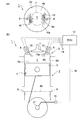
- FIGS. 1 and 2 are schematic views for explaining the basic configuration of the two-stroke gas engine of the present invention, (a) is a top view, and (b) is a cross-sectional view.
- FIGS. 1 and 2 are schematic views for explaining the basic configuration of the two-stroke gas engine of the present invention, (a) is a top view, and (b) is a cross-sectional view.
- the two-stroke gas engine 1 of the present invention can be advanced and retracted into and from a cylindrical cylinder 2, a cylinder head 3 coupled to the upper end side of the cylinder 2, and the cylinder 2.
- a piston 4 housed in the A combustion chamber c is defined between the peripheral wall 2 a of the cylinder 2, the cylinder head 3 and the top surface 4 a of the piston 4.
- symbol 5 in the figure has shown the piston ring.
- a scavenging port 6 is opened in the peripheral wall 2 a on the lower side of the cylinder 2.
- the scavenging port 6 is formed at a position above the top surface 4a (indicated by a two-dot chain line in the drawing) of the piston 4 located near the bottom dead center, and the piston 4 is located near the bottom dead center Occasionally, air is supplied from the scavenging port 6 to the combustion chamber c.
- an exhaust port is opened, and an exhaust valve 7 for opening and closing the exhaust port is provided at the top of the cylinder head 3, and an exhaust valve 7 for opening and closing the exhaust port is provided. The exhaust valve 7 is opened until the piston 4 reaches a position of about 100 ° before top dead center during a scavenging stroke in which the piston 4 is in a rising stroke. Then, the exhaust gas in the previous stroke remaining in the combustion chamber c is scavenged by the air supplied from the scavenging port 6 to the combustion chamber c.
- the cylinder head 3 is provided with a fuel gas injection device 8 (fuel gas injection means) for injecting the fuel gas 8a into the combustion chamber c.
- a fuel oil injection device 10 ignition means for injecting a good fuel oil 10a is provided.
- Two fuel gas injection devices 8 and two fuel oil injection devices 10 are respectively formed at positions separated by 180 ° in the circumferential direction with the cylinder center o as the rotation center.
- the fuel gas injection device 8 and the fuel oil injection device 10 are each provided with four injection holes. Further, in the present invention, the number of installed fuel gas injection devices 8 and the number of fuel oil injection devices 10 are not particularly limited, and may be one, for example. However, in the present embodiment in which the exhaust valve 7 is provided at the top of the cylinder head 3, the plurality of fuel gas injection devices 8 and fuel oil injection devices 10 are arranged at equal intervals in the circumferential direction. Is preferred.
- the fuel gas injection device 8 and the fuel oil injection device 10 are connected to an engine control unit (ECU) 12 via a cable 14 as shown in FIGS. 1 and 2. Further, the ECU 12 is connected via a cable 16 to a crank angle sensor 15 that detects the rotation angle of the crankshaft 17. The phase of the piston 4 is detected by receiving a signal applied to the rotation angle of the crankshaft 17 from the crank angle sensor 15. The fuel gas injection device 8 and the fuel oil injection device 10 inject the fuel gas 8a and the fuel oil 10a into the combustion chamber c at a predetermined timing based on the signal transmitted from the ECU 12. Then, as shown in FIG.
- ECU engine control unit
- the ECU 12 constitutes the fuel gas injection timing control means in the present invention, and ignites the fuel gas in the combustion chamber c by the fuel injection device 10 when the piston 4 is located near the top dead center. Make up the means.
- the vicinity of the top dead center means a state where the piston 4 is located in a range of 10 ° before the top dead center to 20 ° after the top dead center.
- FIG. 3 is a schematic view for explaining the two-stroke gas engine according to the first embodiment of the present invention, in which (a) shows the piston 4 positioned 10 ° to 100 ° before the top dead center. State (b) shows a state in which the piston 4 is located about 5 ° before top dead center, and (c) shows a state in which the piston 4 is located at top dead center.
- the piston 4 when the piston 4 is in the upward stroke and the piston 4 is positioned 10 ° to 100 ° before top dead center (the state shown in FIG. 3A),
- the fuel gas 8b is injected from the fuel gas injection device 8 into the combustion chamber c based on the signal transmitted from the ECU 12 (fuel gas injection timing control means) described above.
- the ECU 12 fuel gas injection timing control means
- the piston 4 is injected in the process of further rising to near the top dead center.
- the fuel gas 8b and the air inside the combustion chamber c are mixed to promote premixing.
- gas-fuel mixture 20 is produced
- the fuel oil 10a having a good compression ignition property is self-ignited, and the fuel gas 8a injected thereby is also burned.
- the combustion flame f is produced
- the combustion flame f propagates to the air-fuel mixture 20 described above, and explosive combustion occurs throughout the combustion chamber c.
- the two-stroke gas engine 1 of the present embodiment injects the fuel gas 8b when the piston 4 is positioned 10 to 100 degrees before the top dead center, and when the piston 4 is positioned near the top dead center.
- the fuel gas 8a and the fuel oil 10a are injected. Therefore, the premixing of the fuel gas 8b injected with the air is promoted when the piston 4 is positioned 10 ° to 100 ° before the top dead center, and the mixture 20 is generated.
- the part is premixed combustion. Therefore, the generation of NOx (nitrogen oxide) can be suppressed as compared with the conventional gas engine in which all of the combustion modes are diffusion combustion.
- the two-stroke gas engine 1 of the present embodiment is configured only by controlling the injection timing of the fuel gas injection device 8 by the fuel gas injection timing control means configured by the ECU 12. Therefore, it is possible to easily promote the premixing in the existing two-stroke gas engine without the need for additional devices and the like.
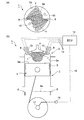
- FIG. 4 is a schematic view for explaining a two-stroke gas engine according to a second embodiment of the present invention, in which (a) shows that the piston 4 is positioned 10 ° to 100 ° before top dead center State (b) shows a state in which the piston 4 is located about 5 ° before top dead center, and (c) shows a state in which the piston 4 is located at top dead center.
- the two-stroke gas engine 1 of the present embodiment differs from the above-described embodiment in that the fuel gas injection means comprises the first fuel gas injection means (the first fuel gas injection device 8A) and the second fuel gas injection means (the second The fuel gas injection device 8B) is separately configured.
- the first fuel gas injection devices 8A are disposed, for example, in the same position and in the same direction as the fuel gas injection devices 8 in the above-described embodiment, and in the same number.
- the second fuel gas injection device 8B is located at an intermediate position between the two first fuel gas injection devices 8A and 8A, and 180 in the circumferential direction centering around the cylinder center o. Two each are formed at a position apart from each other.
- the first fuel gas injection device 8A and the second fuel gas injection device 8B are connected to the above-described ECU 12 (fuel gas injection timing control means).
- the second fuel gas injection is performed.
- the fuel gas 8b is injected from the device 8B toward the combustion chamber c.
- the piston 4 reaches near the top dead center (for example, about 5 ° before the top dead center) based on a signal transmitted from the ECU 12 (fuel gas injection timing control means)
- the fuel gas 8a is injected from the first fuel gas injection device 8A toward the combustion chamber c.
- the fuel oil 10a is injected from the fuel oil injection device 10 substantially simultaneously with the injection of the fuel gas 8a based on the signal transmitted from the ECU 12 (ignition timing control means) It is supposed to be.
- the fuel gas injection means of the present invention is configured separately for the first fuel gas injection means (first fuel gas injection device 8A) and the second fuel gas injection means (second fuel gas injection device 8B). If so, the fuel gas injection directions can be made different between the first fuel gas injection device 8A and the second fuel gas injection device 8B. Therefore, as shown in FIG. 4, the injection direction of the fuel gas 8b injected from the second fuel gas injection device 8B is lower than the injection direction of the fuel gas 8a injected from the first fuel gas injection device 8A. As a result, the fuel gas 8b can be agitated inside the combustion chamber c to promote the premixing of the fuel gas 8b.
- the pressure inside the combustion chamber c is lower than when the piston 4 is near the top dead center. Therefore, as the second fuel gas injection device 8B, a suitable injection device different from the first fuel gas injection device 8A and adapted to the working pressure can be adopted.
- the fuel gas injection means (fuel gas injection device 8) when the piston 4 is in the upward stroke and the piston 4 is positioned 10 ° to 100 ° before top dead center.
- the fuel gas 8b is injected from the second fuel gas injection device 8B) to promote the premixing of the fuel gas 8b and the air, thereby reducing the ratio of diffusion combustion to the entire combustion, thereby reducing NOx ( It is possible to provide a two-stroke gas engine in which the generation of nitrogen oxides is suppressed.
- the ignition means is constituted by the fuel oil injection device 10. Then, as described above, based on the signal transmitted from the ECU 12 (ignition timing control means), the fuel oil injection device 10 injects the fuel oil 10a having high compression ignition property into the combustion chamber c under the high temperature atmosphere.
- the fuel gas in the combustion chamber c is configured to be ignited.
- the ignition means of the present invention is not limited to this.
- an ignition plug provided in the cylinder head 3 is used as the ignition means, and the ignition plug is activated based on a signal transmitted from the ECU 12 (ignition timing control means)
- the fuel gas in the combustion chamber c may be ignited by the spark generated by the spark plug.
- the two-stroke gas engine of the present invention can be suitably used as an engine for ships, particularly for construction machinery, for large vehicles, for power generation, and the like.
Landscapes
- Engineering & Computer Science (AREA)
- Chemical & Material Sciences (AREA)
- Mechanical Engineering (AREA)
- General Engineering & Computer Science (AREA)
- Combustion & Propulsion (AREA)
- Oil, Petroleum & Natural Gas (AREA)
- Chemical Kinetics & Catalysis (AREA)
- General Chemical & Material Sciences (AREA)
- Ceramic Engineering (AREA)
- Combustion Methods Of Internal-Combustion Engines (AREA)
- Electrical Control Of Air Or Fuel Supplied To Internal-Combustion Engine (AREA)
- Fuel-Injection Apparatus (AREA)
Priority Applications (6)
| Application Number | Priority Date | Filing Date | Title |
|---|---|---|---|
| KR1020157028760A KR20150119975A (ko) | 2012-04-11 | 2013-01-31 | 2 사이클 가스 엔진 |
| KR1020147026708A KR20140124862A (ko) | 2012-04-11 | 2013-01-31 | 2 사이클 가스 엔진 |
| US14/382,065 US20150047620A1 (en) | 2012-04-11 | 2013-01-31 | Two-cycle gas engine |
| CN201380015045.XA CN104204440B (zh) | 2012-04-11 | 2013-01-31 | 二冲程燃气发动机 |
| EP13775611.0A EP2837790A4 (en) | 2012-04-11 | 2013-01-31 | TWO STROKE GAS ENGINE |
| US15/149,535 US20160252011A1 (en) | 2012-04-11 | 2016-05-09 | Two-cycle gas engine |
Applications Claiming Priority (2)
| Application Number | Priority Date | Filing Date | Title |
|---|---|---|---|
| JP2012-090231 | 2012-04-11 | ||
| JP2012090231A JP5765819B2 (ja) | 2012-04-11 | 2012-04-11 | 2サイクルガスエンジン |
Related Child Applications (2)
| Application Number | Title | Priority Date | Filing Date |
|---|---|---|---|
| US14/382,065 A-371-Of-International US20150047620A1 (en) | 2012-04-11 | 2013-01-31 | Two-cycle gas engine |
| US15/149,535 Continuation US20160252011A1 (en) | 2012-04-11 | 2016-05-09 | Two-cycle gas engine |
Publications (1)
| Publication Number | Publication Date |
|---|---|
| WO2013153840A1 true WO2013153840A1 (ja) | 2013-10-17 |
Family
ID=49327420
Family Applications (1)
| Application Number | Title | Priority Date | Filing Date |
|---|---|---|---|
| PCT/JP2013/052212 Ceased WO2013153840A1 (ja) | 2012-04-11 | 2013-01-31 | 2サイクルガスエンジン |
Country Status (6)
| Country | Link |
|---|---|
| US (2) | US20150047620A1 (https=) |
| EP (1) | EP2837790A4 (https=) |
| JP (1) | JP5765819B2 (https=) |
| KR (2) | KR20140124862A (https=) |
| CN (3) | CN106014601B (https=) |
| WO (1) | WO2013153840A1 (https=) |
Families Citing this family (10)
| Publication number | Priority date | Publication date | Assignee | Title |
|---|---|---|---|---|
| WO2015123262A1 (en) * | 2014-02-12 | 2015-08-20 | Achates Power, Inc. | A low reactivity, compression-ignition, opposed-piston engine |
| JP2015190328A (ja) * | 2014-03-27 | 2015-11-02 | 三井造船株式会社 | ガスインジェクションエンジンの燃料噴射方式 |
| JP6746268B2 (ja) * | 2014-06-05 | 2020-08-26 | 三菱重工業株式会社 | 内燃機関およびこれを備えた船舶ならびに内燃機関の制御方法 |
| JP6435553B2 (ja) * | 2015-02-03 | 2018-12-12 | 株式会社三井E&Sマシナリー | ハイブリッドガスエンジン船 |
| JP2017207011A (ja) * | 2016-05-19 | 2017-11-24 | 日立オートモティブシステムズ株式会社 | 内燃機関制御装置 |
| CN108223121A (zh) * | 2018-03-26 | 2018-06-29 | 郏政广 | 新型二冲程发动机 |
| JPWO2020183522A1 (https=) * | 2019-03-08 | 2020-09-17 | ||
| JP7813574B2 (ja) * | 2021-12-27 | 2026-02-13 | 株式会社ジャパンエンジンコーポレーション | ガスエンジン |
| GB202213519D0 (en) * | 2022-09-15 | 2022-11-02 | Cosworth Group Holdings Ltd | Improvements in or relating to gaseous fuelled internal combustion engines |
| EP4390101A1 (en) * | 2022-12-19 | 2024-06-26 | Winterthur Gas & Diesel Ltd. | Internal combustion engine |
Citations (5)
| Publication number | Priority date | Publication date | Assignee | Title |
|---|---|---|---|---|
| JPS6245339A (ja) | 1985-08-23 | 1987-02-27 | Sumitomo Chem Co Ltd | 有機溶剤の脱水方法 |
| JPH06137150A (ja) | 1992-10-23 | 1994-05-17 | Ishikawajima Shibaura Mach Co Ltd | ガスエンジンの燃料供給装置 |
| JPH0791256A (ja) * | 1993-09-24 | 1995-04-04 | Kubota Corp | 副室式火花点火エンジンの燃料噴射装置 |
| JP2003247444A (ja) * | 2002-02-21 | 2003-09-05 | Osaka Gas Co Ltd | 火花点火式2サイクルエンジン |
| JP2004036538A (ja) * | 2002-07-04 | 2004-02-05 | Toyota Motor Corp | 混合気を圧縮自着火させる内燃機関、および内燃機関の制御方法 |
Family Cites Families (28)
| Publication number | Priority date | Publication date | Assignee | Title |
|---|---|---|---|---|
| JPS5896113A (ja) * | 1981-12-01 | 1983-06-08 | Mitsubishi Heavy Ind Ltd | 2サイクル内燃機関 |
| CH665453A5 (de) * | 1985-01-11 | 1988-05-13 | Sulzer Ag | Zylinderdeckel fuer eine kolbenbrennkraftmaschine. |
| JPS6245339U (https=) * | 1985-09-10 | 1987-03-19 | ||
| JPH0341068Y2 (https=) * | 1985-12-05 | 1991-08-29 | ||
| JP2538908B2 (ja) * | 1987-03-15 | 1996-10-02 | 三菱重工業株式会社 | 2種燃料エンジンの噴射システム |
| JPH06618Y2 (ja) * | 1987-11-27 | 1994-01-05 | 三菱重工業株式会社 | ガス焚きディーゼルエンジンの燃料供給装置 |
| JPH01318716A (ja) * | 1988-06-17 | 1989-12-25 | Mitsubishi Heavy Ind Ltd | 内燃機関の排気脱硝方法 |
| US4924828A (en) * | 1989-02-24 | 1990-05-15 | The Regents Of The University Of California | Method and system for controlled combustion engines |
| GB8915352D0 (en) * | 1989-07-04 | 1989-08-23 | Ortech Corp | Dual fuel natural gas/diesel 2-stroke engine |
| JPH06257442A (ja) * | 1993-03-05 | 1994-09-13 | Mazda Motor Corp | ユニフロー式2サイクルエンジン |
| DE59406924D1 (de) * | 1993-10-29 | 1998-10-22 | Waertsilae Nsd Schweiz Ag | Hubkolbenbrennkraftmaschine der Dieselbauart |
| KR0141074B1 (ko) * | 1994-10-15 | 1998-07-01 | 김태구 | 압축천연가스 엔진의 플로우 제너레이팅 장치 |
| US6032617A (en) * | 1998-05-27 | 2000-03-07 | Caterpillar Inc. | Dual fuel engine which ignites a homogeneous mixture of gaseous fuel, air, and pilot fuel |
| US6467452B1 (en) * | 2000-07-13 | 2002-10-22 | Caterpillar Inc | Method and apparatus for delivering multiple fuel injections to the cylinder of an internal combustion engine |
| US6526939B2 (en) * | 2001-04-27 | 2003-03-04 | Wisconsin Alumni Research Foundation | Diesel engine emissions reduction by multiple injections having increasing pressure |
| US6668789B1 (en) * | 2001-08-23 | 2003-12-30 | Wisconsin Alumni Research Foundation | Internal combustion engine using premixed combustion of stratified charges |
| US6840237B2 (en) * | 2002-12-30 | 2005-01-11 | Ford Global Technologies, Llc | Method for auto-ignition operation and computer readable storage device |
| JP4033160B2 (ja) * | 2004-03-30 | 2008-01-16 | トヨタ自動車株式会社 | 予混合圧縮自着火運転が可能な内燃機関の制御装置 |
| JP4100401B2 (ja) * | 2005-02-24 | 2008-06-11 | トヨタ自動車株式会社 | 内燃機関 |
| DE102006014071B3 (de) * | 2006-03-27 | 2007-10-25 | MOT Forschungs- und Entwicklungsgesellschaft für Motorentechnik, Optik, Thermodynamik mbH | Brennverfahren einer Brennkraftmaschine und Brennkraftmaschine |
| US9010293B2 (en) * | 2006-04-07 | 2015-04-21 | David A. Blank | Combustion control via homogeneous combustion radical ignition (HCRI) or partial HCRI in cyclic IC engines |
| JP4989281B2 (ja) * | 2007-04-10 | 2012-08-01 | 株式会社ニッキ | ガスエンジンの燃料供給方法及びガソリン代替ガス燃料噴射制御装置 |
| DE102008041237A1 (de) * | 2008-08-13 | 2010-02-18 | Robert Bosch Gmbh | Verfahren zur Kraftstoffeinbringung in einen Brennraum einer Brennkraftmaschine |
| US8616177B2 (en) * | 2010-02-11 | 2013-12-31 | Wisconsin Alumni Research Foundation | Engine combustion control via fuel reactivity stratification |
| KR101411395B1 (ko) * | 2010-08-05 | 2014-06-25 | 가부시키가이샤 아이에이치아이 | 2사이클 엔진 |
| JP5587091B2 (ja) * | 2010-08-05 | 2014-09-10 | 株式会社ディーゼルユナイテッド | 2ストロークガス機関 |
| CN202001108U (zh) * | 2011-01-31 | 2011-10-05 | 武汉理工大学 | 船用发动机双燃料供给系统 |
| JP5851918B2 (ja) * | 2012-04-11 | 2016-02-03 | 三菱重工業株式会社 | 二元燃料ディーゼルエンジン及びその運転方法 |
-
2012
- 2012-04-11 JP JP2012090231A patent/JP5765819B2/ja active Active
-
2013
- 2013-01-31 KR KR1020147026708A patent/KR20140124862A/ko not_active Ceased
- 2013-01-31 CN CN201610333674.2A patent/CN106014601B/zh active Active
- 2013-01-31 EP EP13775611.0A patent/EP2837790A4/en not_active Withdrawn
- 2013-01-31 CN CN201380015045.XA patent/CN104204440B/zh active Active
- 2013-01-31 US US14/382,065 patent/US20150047620A1/en not_active Abandoned
- 2013-01-31 KR KR1020157028760A patent/KR20150119975A/ko not_active Ceased
- 2013-01-31 WO PCT/JP2013/052212 patent/WO2013153840A1/ja not_active Ceased
- 2013-01-31 CN CN201610335130.XA patent/CN105971719B/zh active Active
-
2016
- 2016-05-09 US US15/149,535 patent/US20160252011A1/en not_active Abandoned
Patent Citations (5)
| Publication number | Priority date | Publication date | Assignee | Title |
|---|---|---|---|---|
| JPS6245339A (ja) | 1985-08-23 | 1987-02-27 | Sumitomo Chem Co Ltd | 有機溶剤の脱水方法 |
| JPH06137150A (ja) | 1992-10-23 | 1994-05-17 | Ishikawajima Shibaura Mach Co Ltd | ガスエンジンの燃料供給装置 |
| JPH0791256A (ja) * | 1993-09-24 | 1995-04-04 | Kubota Corp | 副室式火花点火エンジンの燃料噴射装置 |
| JP2003247444A (ja) * | 2002-02-21 | 2003-09-05 | Osaka Gas Co Ltd | 火花点火式2サイクルエンジン |
| JP2004036538A (ja) * | 2002-07-04 | 2004-02-05 | Toyota Motor Corp | 混合気を圧縮自着火させる内燃機関、および内燃機関の制御方法 |
Non-Patent Citations (1)
| Title |
|---|
| See also references of EP2837790A4 |
Also Published As
| Publication number | Publication date |
|---|---|
| US20150047620A1 (en) | 2015-02-19 |
| EP2837790A1 (en) | 2015-02-18 |
| CN104204440A (zh) | 2014-12-10 |
| CN105971719A (zh) | 2016-09-28 |
| EP2837790A4 (en) | 2015-12-02 |
| CN105971719B (zh) | 2018-11-30 |
| JP2013217334A (ja) | 2013-10-24 |
| CN106014601A (zh) | 2016-10-12 |
| KR20150119975A (ko) | 2015-10-26 |
| CN106014601B (zh) | 2019-06-04 |
| US20160252011A1 (en) | 2016-09-01 |
| CN104204440B (zh) | 2016-11-16 |
| JP5765819B2 (ja) | 2015-08-19 |
| KR20140124862A (ko) | 2014-10-27 |
Similar Documents
| Publication | Publication Date | Title |
|---|---|---|
| JP5765819B2 (ja) | 2サイクルガスエンジン | |
| WO2013153842A1 (ja) | 2サイクルガスエンジン | |
| EP3001008B9 (en) | Turbulent jet ingnition pre-chamber combustion system for spark ignition engines | |
| US8794212B2 (en) | Engine and method of operating engine | |
| CN104126066B (zh) | 双燃料柴油发动机 | |
| CN103452682B (zh) | 用于操作发动机的方法 | |
| JP2010144516A (ja) | ガスエンジンの予燃焼器 | |
| JP2005232988A (ja) | 副室式エンジン | |
| JP4086440B2 (ja) | エンジン | |
| JP2016006325A (ja) | 2サイクルガスエンジン及び2サイクルガスエンジン用の燃料ガス噴射システム | |
| JPH09268916A (ja) | 重油を燃料とするディーゼルエンジン | |
| JP2005232987A (ja) | 副室式エンジン | |
| JP2013234596A (ja) | 2サイクル副室式ガスエンジン | |
| JP2006316777A (ja) | 内燃機関 | |
| JP5056540B2 (ja) | スパークアシストディーゼルエンジン | |
| JP7527440B1 (ja) | 内燃機関 | |
| JP2015163795A (ja) | 2サイクルガスエンジン及び2サイクルガスエンジン用の燃料ガス噴射システム | |
| JP2004285928A (ja) | エンジン及びその運転方法 | |
| JP2007162631A (ja) | 内燃機関の制御装置 | |
| JP5608723B2 (ja) | ガスエンジンの燃焼方法及び装置 | |
| JP4410744B2 (ja) | 筒内噴射式火花点火エンジン | |
| JP2009191683A (ja) | スパークアシストディーゼルエンジン | |
| JP2009191729A (ja) | スパークアシストディーゼルエンジン | |
| JP2006063863A (ja) | 内燃機関 |
Legal Events
| Date | Code | Title | Description |
|---|---|---|---|
| 121 | Ep: the epo has been informed by wipo that ep was designated in this application |
Ref document number: 13775611 Country of ref document: EP Kind code of ref document: A1 |
|
| REEP | Request for entry into the european phase |
Ref document number: 2013775611 Country of ref document: EP |
|
| WWE | Wipo information: entry into national phase |
Ref document number: 14382065 Country of ref document: US Ref document number: 2013775611 Country of ref document: EP |
|
| ENP | Entry into the national phase |
Ref document number: 20147026708 Country of ref document: KR Kind code of ref document: A |
|
| NENP | Non-entry into the national phase |
Ref country code: DE |