WO2013147188A1 - 多孔質中空糸膜の製造方法、及び製造装置 - Google Patents
多孔質中空糸膜の製造方法、及び製造装置 Download PDFInfo
- Publication number
- WO2013147188A1 WO2013147188A1 PCT/JP2013/059596 JP2013059596W WO2013147188A1 WO 2013147188 A1 WO2013147188 A1 WO 2013147188A1 JP 2013059596 W JP2013059596 W JP 2013059596W WO 2013147188 A1 WO2013147188 A1 WO 2013147188A1
- Authority
- WO
- WIPO (PCT)
- Prior art keywords
- hollow fiber
- porous hollow
- fiber membrane
- bundle
- shaft
- Prior art date
- Legal status (The legal status is an assumption and is not a legal conclusion. Google has not performed a legal analysis and makes no representation as to the accuracy of the status listed.)
- Ceased
Links
Images

Classifications
-
- B—PERFORMING OPERATIONS; TRANSPORTING
- B01—PHYSICAL OR CHEMICAL PROCESSES OR APPARATUS IN GENERAL
- B01D—SEPARATION
- B01D69/00—Semi-permeable membranes for separation processes or apparatus characterised by their form, structure or properties; Manufacturing processes specially adapted therefor
- B01D69/08—Hollow fibre membranes
-
- B—PERFORMING OPERATIONS; TRANSPORTING
- B01—PHYSICAL OR CHEMICAL PROCESSES OR APPARATUS IN GENERAL
- B01D—SEPARATION
- B01D69/00—Semi-permeable membranes for separation processes or apparatus characterised by their form, structure or properties; Manufacturing processes specially adapted therefor
- B01D69/08—Hollow fibre membranes
- B01D69/087—Details relating to the spinning process
- B01D69/0871—Fibre guidance after spinning through the manufacturing apparatus
-
- B—PERFORMING OPERATIONS; TRANSPORTING
- B01—PHYSICAL OR CHEMICAL PROCESSES OR APPARATUS IN GENERAL
- B01D—SEPARATION
- B01D71/00—Semi-permeable membranes for separation processes or apparatus characterised by the material; Manufacturing processes specially adapted therefor
- B01D71/06—Organic material
- B01D71/26—Polyalkenes
- B01D71/261—Polyethylene
-
- B—PERFORMING OPERATIONS; TRANSPORTING
- B01—PHYSICAL OR CHEMICAL PROCESSES OR APPARATUS IN GENERAL
- B01D—SEPARATION
- B01D71/00—Semi-permeable membranes for separation processes or apparatus characterised by the material; Manufacturing processes specially adapted therefor
- B01D71/06—Organic material
- B01D71/26—Polyalkenes
- B01D71/262—Polypropylene
-
- D—TEXTILES; PAPER
- D02—YARNS; MECHANICAL FINISHING OF YARNS OR ROPES; WARPING OR BEAMING
- D02J—FINISHING OR DRESSING OF FILAMENTS, YARNS, THREADS, CORDS, ROPES OR THE LIKE
- D02J1/00—Modifying the structure or properties resulting from a particular structure; Modifying, retaining, or restoring the physical form or cross-sectional shape, e.g. by use of dies or squeeze rollers
- D02J1/22—Stretching or tensioning, shrinking or relaxing, e.g. by use of overfeed and underfeed apparatus, or preventing stretch
Definitions
- the present invention relates to a method for manufacturing a porous hollow fiber membrane and a manufacturing apparatus.
- polyolefin porous hollow fiber membranes produced by melt spinning a crystalline polyolefin and then drawing it are excellent in chemical stability, strength characteristics, flexibility, etc. It is used in a wide range of fields such as pure water production and air purification.
- the production of such a porous hollow fiber membrane includes a spinning process in which a polyolefin such as polyethylene and polypropylene is melt-spun to obtain a hollow fiber precursor, and the hollow fiber precursor obtained in the spinning process is stretched to obtain a porous material.
- a hydrophilization process in which a porous hollow fiber membrane precursor is subjected to a hydrophilization treatment to form a porous hollow fiber membrane (for example, Patent Documents 1 to 3). 4).
- the hydrophilization step includes a step of immersing a plurality of weights of porous hollow fiber membrane precursors in a tank of a hydrophilizing agent solution or dispersion liquid while carrying them in parallel to form a porous hollow fiber membrane, and excessive evaporation. It comprises a heat retaining step for removing excess hydrophilizing agent solution or dispersion adhering to the membrane surface while preventing, and a step for drying the hydrophilizing agent solution or dispersion.
- the roller that transports the porous hollow fiber membranes or the bundle thereof is formed on the surface in order to prevent the porous hollow fiber membranes or the bundles conveyed adjacent to each other from contacting each other.
- a roller provided with a plurality of grooves is used. This groove extends in the circumferential direction of the roller, and a single porous hollow fiber membrane or a bundle of one porous hollow fiber membrane is placed in one groove so that the porous hollow fiber membrane is conveyed during the conveyance of the porous hollow fiber membrane.
- the porous hollow fiber membrane or the bundle of porous hollow fiber membranes is prevented from moving in the axial direction of the roller.
- the present invention has been made to solve the above-described problems, and in the manufacturing stage of the porous hollow fiber membrane, the porous hollow fiber can reliably prevent the porous hollow fiber membrane from being damaged. It aims at providing the manufacturing method and manufacturing apparatus of a thread membrane.
- the present invention provides a porous hollow fiber membrane production apparatus for producing a porous hollow fiber membrane by adhering a solution or dispersion to the surface, wherein grooves are formed on the outer surface.
- a shaft that conveys a porous hollow fiber membrane or a bundle thereof by rotating around its axis, a grooveless roller having a flange provided at each end of the shaft, and a porous grooved roller And a plurality of grooved rollers arranged so as to form a conveyance path for conveying the hollow fiber membrane or the bundle thereof.
- the transport position of the transported porous hollow fiber membrane or the bundle thereof on the grooveless roller can be adjusted.
- the porous hollow fiber membrane or the bundle being conveyed is being conveyed by setting the position of the porous hollow fiber membrane or the bundle on the grooveless roller by a grooved roller to a position away from the collar by a predetermined distance. If you don't hit your head, As a result, even if the solution or dispersion adhering to the surface of the porous hollow fiber membrane travels along the shaft and adheres to the brim and solidifies on the surface of the brim, the porous hollow fiber membrane is made by the solidified solution or dispersion Can be prevented from being damaged.
- the plurality of grooved rollers are preferably arranged in pairs on the upstream side and the downstream side of the conveyance path with respect to the shaft.
- each of the paired grooved rollers is preferably disposed in a dryer for drying the solution or dispersion adhering to the porous hollow fiber membrane.
- the present invention provides a method for producing a porous hollow fiber membrane, comprising the steps of attaching a solution or dispersion to the surface of the porous hollow fiber membrane, and the step of attaching the solution. And a step of transporting the porous hollow fiber membrane or a bundle thereof. In this transporting step, no groove is formed on the outer surface, and the porous hollow fiber membrane or the A porous hollow fiber membrane or a bundle thereof is transported at a predetermined distance away from the collar by using a shaft for conveying the bundle and a grooveless roller having collars provided at both ends of the shaft. It is said.
- the transport position of the transported porous hollow fiber membrane or the bundle thereof on the grooveless roller can be adjusted.
- the porous hollow fiber membrane or the bundle being conveyed is being conveyed by setting the position of the porous hollow fiber membrane or the bundle on the grooveless roller by a grooved roller to a position away from the collar by a predetermined distance. If you don't hit your head, As a result, even if the solution or dispersion adhering to the surface of the porous hollow fiber membrane travels along the shaft and adheres to the brim and solidifies at the surface of the brim, the porous hollow fiber membrane is solidified by the solidified solution or dispersion. Can be prevented from being damaged.
- the porous hollow fiber is disposed in the dryer using a plurality of grooved rollers disposed so as to form a transport path for transporting the porous hollow fiber membrane or a bundle thereof together with the grooveless roller. It is preferable to transport the film or its bundle at a position where it does not contact the brim.
- the solution or dispersion is preferably a hydrophilizing agent solution or dispersion.
- the present invention provides a porous hollow fiber membrane in which a bundle of a plurality of spindles of a porous hollow fiber membrane is conveyed and immersed in a hydrophilizing agent solution or dispersion tank.
- a grooveless roller having flanges provided at both ends of the shaft, and a plurality of grooves arranged so as to form a conveyance path for conveying the porous hollow fiber membrane or the bundle thereof together with the grooveless roller.
- a porous hollow fiber membrane or a bundle thereof is conveyed using a roller at a position away from the collar by a predetermined distance.
- the transport position of the transported porous hollow fiber membrane or the bundle thereof on the grooveless roller can be adjusted.
- the porous hollow fiber membrane or the bundle being conveyed is being conveyed by setting the position of the porous hollow fiber membrane or the bundle on the grooveless roller by a grooved roller to a position away from the collar by a predetermined distance. If you don't hit your head, As a result, even if the solution or dispersion adhering to the surface of the porous hollow fiber membrane travels along the shaft and adheres to the brim and solidifies at the surface of the brim, the porous hollow fiber membrane is solidified by the solidified solution or dispersion. Can be prevented from being damaged.
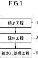
- FIG. 1 is a block diagram showing a process for producing a porous hollow fiber membrane.
- a spinning process 1 in which a molten resin is cooled and solidified to form a precursor of the porous hollow fiber membrane, and a precursor of the porous hollow fiber membrane are used.
- the spinning step 1 for example, the molten resin discharged from a spinning head having four nozzles is cooled and solidified, and the precursors of four porous hollow fiber membranes are bundled and wound up with one bobbin. ing.
- the stretching step 3 a tensile force is applied to the bundled precursors of the porous hollow fiber membranes so that the bundles are gradually stretched.
- FIG. 2 is a block diagram showing a hydrophilic treatment process.
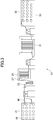
- FIG. 3 is a schematic view showing a hydrophilic treatment apparatus used in the hydrophilic treatment step.
- the hydrophilization treatment step 5 includes an impregnation step 7 in which a porous hollow fiber membrane M is formed by immersing a precursor of the porous hollow fiber membrane in a solution tank containing a solution or dispersion of a hydrophilizing agent.
- a winding step 13 for winding the porous hollow fiber membrane.
- the hydrophilic treatment apparatus 17 is attached with a plurality of bobbins 19 wound up with the precursor of the stretched porous hollow fiber membrane M from the upstream side in the transport direction of the porous hollow fiber membrane M.
- the number of the grooveless rollers 27 provided in the heat insulating tank 25 is not particularly limited, and some of the rollers in the heat insulating tank 25 may be the grooveless rollers 27, or all the rollers may have no grooves.
- the roller 27 may be used. While the bundle of the porous hollow fiber membranes M is being conveyed by the grooveless roller 27, the surplus of the hydrophilizing agent solution or dispersion adhering to the surface of the porous hollow fiber membrane M is dropped off. The excess drop rate of the agent solution or dispersion varies depending on the number of porous hollow fiber membranes M and the pore diameter. Therefore, it is preferable that the number of the grooveless rollers 27 provided in the heat insulating tank 25 is appropriately selected according to the number of the porous hollow fiber membranes M and the pore diameter.
- the porous hollow fiber membrane M stretched in the stretching step 3 is unwound from the bobbin 21 of the yarn feeding creel 19, and a solution or dispersion liquid of the hydrophilizing agent is stored in the discharged hollow hollow fiber membrane M.
- the solution is conveyed through the solution tank 23.
- a plurality of porous hollow fiber membranes M are wound around the bobbin 19, and when feeding out from the yarn feeding creel 21, a plurality of porous hollow fiber membranes M from the plurality of bobbins 19 are wound on one bobbin 19. It comes out as a bundle.
- a solution or dispersion of a hydrophilizing agent is stored in the solution tank 23 . And the hydrophilic agent is made to adhere to the precursor of the porous hollow fiber membrane M by allowing the precursor of the porous hollow fiber membrane M to pass through the inside of the solution tank 23.
- hydrophilizing agent that can be used in the present invention, hydrophilic block polymers such as ethylene-vinyl alcohol block copolymers and ethylene-vinyl acetate block copolymers can be used.
- the solvent or dispersion of these hydrophilizing agents or dispersions may be water or organic solvents or water miscible with water such as methanol, ethanol, N-propanol, isopropyl alcohol, dimethyl sulfoxide, dimethylformamide. And a mixed solvent of these organic solvents.
- the porous hollow fiber membrane M having a hydrophilic agent solution or dispersion adhering to the surface is transported in a heat retaining tank 25 maintained at a predetermined temperature and humidity, and the porous hollow fiber membrane is transported. While preventing excessive evaporation of the solution or dispersion of the hydrophilizing agent adhering to the surface of M, the excess hydrophilizing agent solution or dispersion is dropped.
- the bundle of the porous hollow fiber membranes M in which the solution or dispersion of the hydrophilizing agent has been adapted is conveyed over a predetermined distance, and the hydrophilic agent is dried on the surface of the porous hollow fiber membrane M. It is designed to solidify.
- the porous hollow fiber membrane M to which the hydrophilizing agent is attached is wound on the bobbin 35.
- the bundle of porous hollow fiber membranes M is disassembled and wound around the bobbin 35 in the state of the bundle wound around the bobbin 19 of the yarn feeding creel 21.
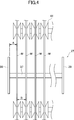
- FIG. 4 is a top view showing the grooveless roller.
- the porous hollow fiber membrane M is drawn so as to cross the grooveless rollers 27. ing.
- the grooveless roller 27 includes a shaft 37 extending in the horizontal direction and a pair of flanges 39 attached to both ends of the shaft 37.
- a bundle of a plurality of weights of the porous hollow fiber membrane M is applied at intervals in the axial direction of the shaft 37.
- a groove for positioning the bundle of porous hollow fiber membranes M with respect to the shaft 37 is not formed in the shaft 37.
- the bundle closest to the flange 39 of the grooveless roller 27 is located at a distance from the flange 39 in the central direction of the shaft 37 by a predetermined distance A. It is applied to the shaft 37.
- a pair of grooved rollers 41 is provided on the upstream side in the transport direction of the grooveless roller 27 and on the downstream side in the transport direction.
- Each of the plurality of grooved rollers 41 is formed with a groove for accommodating a bundle of porous hollow fiber membranes M in the vicinity of the center in the axial direction on the peripheral surface. The interval between the bundle of porous hollow fiber membranes M adjacent to the flange 39 of the non-roller 27 and the interval between adjacent bundles of porous hollow fiber membranes M are maintained.
- the plurality of grooved rollers 41 are held in a row so as to be rotatable around the same axis.
- the two grooved rollers 41 on the outer side of the row are held so that the center in the axial direction is at a distance A from the inner surface of the flange 39.
- the remaining grooved rollers 41 are held such that the distance between the centers in the axial direction is the distance B.
- a dryer is provided on each of the upstream and downstream sides in the conveying direction of the grooveless roller 27, and a plurality of upstream and downstream grooved rollers 41 are disposed in the dryer.
- the above-mentioned distance A is determined as follows.
- the hydrophilic agent solution or dispersion adhering to the porous hollow fiber membrane M When the hydrophilic agent solution or dispersion adhering to the porous hollow fiber membrane M is deposited on the surface of the shaft 37, the hydrophilic agent solution or dispersion gradually spreads in the axial direction of the shaft 37.
- the brim 39 formed at the end of the shaft 37 spreads in the radial direction of the shaft 37 the hydrophilizing agent solution or dispersion that has spread in the axial direction and has reached the brim 39. If the distance A between the brim 39 and the bundle of the porous hollow fiber membranes M is too short, the brim 39 and the porous hollow fiber membrane M to which the solidified material is attached come into contact and damage the membrane. On the other hand, if the distance A is too long, the shaft 37 becomes longer and the entire grooveless roller 27 becomes larger.
- the distance A between the flange 39 and the bundle of the porous hollow fiber membranes M is not less than the deflection width in the axial direction of the shaft 37 of the yarn path through which the bundle of the porous hollow fiber membranes M passes throughout the hydrophilization process. Specifically, it is preferable that the thickness is 10 to 50 mm.
- the flange 39 at the end of the shaft 37, it is possible to prevent the bundle of the porous hollow fiber membranes M stretched over the shaft 37 from falling off the shaft 37. Further, by providing the flange 39 at the end of the shaft 37, the threading operation of the bundle of the porous hollow fiber membranes M can be facilitated.
- the distance B between adjacent bundles of the bundle of porous hollow fiber membranes M of a plurality of spindles it is preferable to shorten the distance B between adjacent bundles of the bundle of porous hollow fiber membranes M of a plurality of spindles.
- the hydrophilic agent solution or dispersion adhering to the porous hollow fiber membrane M adheres to the shaft 37, the hydrophilic agent solution or dispersion spreads in the axial direction of the shaft 37, but the distance B is shortened.
- the surface of the shaft 37 can always be kept wet by the solution or dispersion of the hydrophilic agent adhering to the shaft 37 from the porous hollow fiber membrane M. Can be prevented from solidifying.
- the distance B needs to be a distance at which the hydrophilizing agent does not solidify in the environment inside the heat insulating tank 25, and is preferably a distance close to zero. Further, when the distance B is increased, the length of the shaft 37 is also required, and it is preferable that the shaft B is short in order to reduce the size of the heat insulating tank 25.
- the distance A between the flange 39 and the bundle of the porous hollow fiber membranes M it is possible to prevent the dispersion from adhering to the flange 39 and the solidified product from damaging the porous hollow fiber membrane M. Furthermore, by shortening the distance B between adjacent bundles of the porous hollow fiber membrane M as much as possible, it is possible to prevent the hydrophilic agent from unnecessarily solidifying on the surface of the shaft 39 and to reduce the size of the heat insulating tank 25. I can do it. Moreover, by providing the flange 39, it is possible to prevent the bundle of the porous hollow fiber membranes M from dropping off during the yarn threading operation.
- the flange 39 is formed at both ends of the shaft 37, so that the entire length of the shaft 37 can be shortened and the heat insulating tank 25 can be downsized. That is, when the hydrophilizing agent attached to the porous hollow fiber membrane M adheres to the shaft 37, the hydrophilizing agent spreads in the axial direction of the shaft 37 from the attached portion and solidifies. In order not to solidify on the transport path of the film M, the transport path needs to be sufficiently separated in the axial direction of the shaft 37.
- the flanges 39 at both ends of the shaft 37, when the hydrophilizing agent flows in the axial direction of the shaft 37 and reaches the flange 39, the surface of the flange 39 is spread over in the radial direction of the shaft 39 and solidified. To do.
- the flange 39 it is possible to secure a space for solidifying the hydrophilizing agent outside the transport path of the porous hollow fiber membrane M. As a result, it is not necessary to secure a space for solidifying the hydrophilizing agent in the axial direction of the shaft 37, so that the shaft 37 can be shortened.
- hydrophilizing agent adhesion rate measuring method described below may be applied to the above-described hydrophilization treatment step.
- the method for measuring the hydrophilizing agent adhesion rate is the weight of the precursor of the porous hollow fiber membrane before introducing the precursor of the porous hollow fiber membrane into the solution tank, and the weight of the porous hollow fiber membrane that has passed through the solution tank. From this difference, the amount of the hydrophilizing agent attached to the porous hollow fiber membrane is measured.
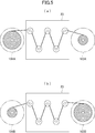
- FIG. 5 is a schematic diagram for explaining the method for measuring the adhesion rate of the hydrophilizing agent.
- the feeding bobbin 101 and the winding bobbin 103 are respectively arranged before and after the solution tank 23. And the total weight of the precursor before the feeding bobbin 101 and there wound porous hollow fiber membrane subjected to impregnation treatment to the precursor of the porous hollow fiber membrane and w 1, a bobbin 103 and therein for winding
- the total weight of the wound porous hollow fiber membrane is w 2
- the bobbin 101 for feeding after impregnating the precursor of the porous hollow fiber membrane and the total weight of the porous hollow fiber membrane wound around the bobbin 101 Is w 3
- the total weight of the winding bobbin 103 and the porous hollow fiber membrane wound thereon is assumed to be w 4 .
- the total weight of the precursor of the porous hollow fiber membrane is calculated by w 1 -w 3
- the total weight of the porous hollow fiber membrane subjected to the impregnation treatment is calculated by w 4 -w 2 .
- the adhesion rate of a hydrophilizing agent is determined by the following numerical formula 1.
- hydrophilizing agent adhesion rate calculated by Equation 1 to about 7-13 wt%
- an appropriate amount of hydrophilizing agent can be adhered to the precursor of the porous hollow fiber membrane.
- This hydrophilizing agent adhesion rate can be appropriately adjusted according to the hydrophilicity of the hydrophilizing agent, the raw material density, and the surface area including the pore surface.
Landscapes
- Chemical & Material Sciences (AREA)
- Chemical Kinetics & Catalysis (AREA)
- Engineering & Computer Science (AREA)
- Textile Engineering (AREA)
- Separation Using Semi-Permeable Membranes (AREA)
- Yarns And Mechanical Finishing Of Yarns Or Ropes (AREA)
Description
本発明は、多孔質中空糸膜の製造方法、及び製造装置に関する。
従来から、結晶性ポリオレフィンを溶融紡糸した後、延伸して製造されたポリオレフィン製多孔質中空糸膜は、化学的安定性、強度特性、柔軟性等に優れていることから、廃水の処理、超純水の製造、空気の浄化等の幅広い分野で利用されている。このような多孔質中空糸膜の製造は、ポリエチレン、ポリプロピレン等のポリオレフィンを溶融紡糸して中空糸の前駆体を得る紡糸工程と、紡糸工程で得られた中空糸の前駆体を延伸して多孔質化する延伸工程と、多孔質化された多孔質中空糸膜の前駆体の表面に親水化処理を施して多孔質中空糸膜とする親水化工程とを備えている(例えば特許文献1乃至4)。
一般的に、紡糸工程では、例えば4個のノズルから紡出された4本の多孔質中空糸膜の前駆体の束を、同時に一つのボビンで巻き取るようになっており、延伸工程及び親水化工程では、例えば6個のボビンから繰り出された合計24本の多孔質中空糸膜の前駆体の束を一錘の束として処理を行うようになっている。そして親水化工程は、複数錘の多孔質中空糸膜の前駆体を平行に搬送しながら親水化剤の溶液または分散液の槽に浸して多孔質中空糸膜とする工程と、過剰な蒸発を防ぎながら膜表面に付着した過剰な親水化剤の溶液または分散液を脱落さる保温工程と、親水化剤の溶液または分散液を乾燥させる工程とを備えている。
一般的に、親水化工程における、多孔質中空糸膜又はその束を搬送するローラーは、隣接して搬送される多孔質中空糸膜又はその束同士が接触するのを防止するために、表面に複数の溝が設けられたローラーが用いられている。この溝は、ローラーの周方向に延びており、一本の多孔質中空糸膜又は一錘の多孔質中空糸膜の束を一つの溝内に入れて多孔質中空糸膜の搬送中に多孔質中空糸膜又は多孔質中空糸膜の束がローラーの軸方向に移動するのを防止するようになっている。
しかしながら、このようなローラーで、膜表面に過剰な親水化剤の溶液または分散液が付着した多孔質中空糸膜又はその束を搬送した場合、溝の壁面に親水化剤の溶液または分散液が付着して固化するので、この親水化剤の固化物によって溝内を通過する多孔質中空糸膜を傷つけてしまうという問題があった。
そこで本発明は、上述した問題点を解決するためになされたものであり、多孔質中空糸膜の製造段階において、多孔質中空糸膜が傷付くのを確実に防止することができる多孔質中空糸膜の製造方法、及び製造装置を提供することを目的とする。
上述した課題を解決するために、本発明は、表面に溶液又は分散液を付着させて多孔質中空糸膜を製造する多孔質中空糸膜の製造装置であって、外表面に溝が形成されておらず、その軸周りに回転することで多孔質中空糸膜又はその束を搬送するシャフト、及びこのシャフトの両端部に各々設けられたツバを有する溝無しローラーと、溝無しローラーと共に多孔質中空糸膜又はその束を搬送する搬送経路を形成するように配置された複数の溝付きローラーと、を備えることを特徴とする。
このように構成された本発明によれば、溝付きローラーを用いることによって、搬送される多孔質中空糸膜又はその束の溝無しローラー上での搬送位置を調整できるようになる。そして溝付きローラーによって、多孔質中空糸膜又はその束の溝無しローラー上での位置を、ツバから所定距離離れた位置にすることによって、搬送される多孔質中空糸膜又はその束が搬送中にツバに当たらなくなる。これにより、多孔質中空糸膜の表面に付着していた溶液又は分散液がシャフトを伝ってツバに付着し、ツバの表面で固化したとしても、固化した溶液又は分散液によって多孔質中空糸膜が傷付くのを防止することができる。
この場合において、複数の溝付きローラーは、シャフトに対して搬送経路の上流側と下流側に対をなして配置されていることが好ましい。
この場合において、対をなす溝付きローラーの各々は、多孔質中空糸膜に付着した溶液又は分散液を乾燥させるための乾燥機内に配置されていることが好ましい。
また、上述した課題を解決するために、本発明は、多孔質中空糸膜の製造方法であって、多孔質中空糸膜の表面に溶液又は分散液を付着させる工程と、この付着させる工程の後、多孔質中空糸膜又はその束を搬送する工程とを備え、この搬送する工程では、外表面に溝が形成されておらず、その軸周りに回転することで多孔質中空糸膜又はその束を搬送するシャフト、及びこのシャフトの両端部に各々設けられたツバを有する溝無しローラーを用いて多孔質中空糸膜又はその束を、ツバから所定の距離離れた位置で搬送することを特徴としている。
このように構成された本発明によれば、溝付きローラーを用いることによって、搬送される多孔質中空糸膜又はその束の溝無しローラー上での搬送位置を調整できるようになる。そして溝付きローラーによって、多孔質中空糸膜又はその束の溝無しローラー上での位置を、ツバから所定距離離れた位置にすることによって、搬送される多孔質中空糸膜又はその束が搬送中にツバに当たらなくなる。これにより、多孔質中空糸膜の表面に付着していた溶液又は分散液がシャフトを伝ってツバに付着し、ツバの表面で固化したとしても、固化した溶液又は分散液によって多孔質中空糸膜が傷付くのを防止することができる。
この場合において、乾燥機内に配置されており、溝無しローラーと共に多孔質中空糸膜又はその束を搬送する搬送経路を形成するように配置された複数の溝付きローラーを用いて、多孔質中空糸膜又はその束がツバに接触しない位置で搬送することが好ましい。
この場合において、溶液又は分散液は、親水化剤の溶液または分散液であることが好ましい。
また、上記課題を解決するために、本発明は、複数錘の多孔質中空糸膜の前駆体の束を搬送して親水化剤の溶液または分散液の槽に浸して多孔質中空糸膜とする工程と、複数錘の多孔質中空糸膜の束を親水化剤の溶液または分散液の槽から引き上げる工程と保温工程とを備え、この保温工程では、外周面に溝が形成されていないシャフト、及びこのシャフトの両端部に各々設けられたツバを有する溝無しローラーと、この溝無しローラーと共に多孔質中空糸膜又はその束を搬送する搬送経路を形成するように配置された複数の溝付きローラーとを用いて多孔質中空糸膜又はその束を、ツバから所定の距離離れた位置で搬送することを特徴としている。
このように構成された本発明によれば、溝付きローラーを用いることによって、搬送される多孔質中空糸膜又はその束の溝無しローラー上での搬送位置を調整できるようになる。そして溝付きローラーによって、多孔質中空糸膜又はその束の溝無しローラー上での位置を、ツバから所定距離離れた位置にすることによって、搬送される多孔質中空糸膜又はその束が搬送中にツバに当たらなくなる。これにより、多孔質中空糸膜の表面に付着していた溶液又は分散液がシャフトを伝ってツバに付着し、ツバの表面で固化したとしても、固化した溶液又は分散液によって多孔質中空糸膜が傷付くのを防止することができる。
以上のように本発明によれば、多孔質中空糸膜の製造段階において、多孔質中空糸膜が傷付くのを確実に防止することができる。
以下、図面を参照して、本発明の実施形態について説明する。
図1は、多孔質中空糸膜を製造する工程を示すブロック図である。
図1に示すように、多孔質中空糸膜を製造するためには、溶融樹脂を冷却固化して多孔質中空糸膜の前駆体とする紡糸工程1と、多孔質中空糸膜の前駆体を延伸して微細孔を形成する延伸工程3と、多孔質中空糸膜の前駆体の表面に親水化ポリマーをコーティングして親水化処理を施して多孔質中空糸膜とする親水化処理工程5とを行う。
紡糸工程1では、例えば4個のノズルを有する紡糸ヘッドから吐出された溶融樹脂を冷却固化し、4本の多孔質中空糸膜の前駆体を一束にして一つのボビンで巻き取るようになっている。そして延伸工程3では、束にされた多孔質中空糸膜の前駆体に引張力を作用させ徐々に引き延ばすようになっている。
図2は、親水化処理工程を示すブロック図である。また、図3は、親水化処理工程で使用される親水化処理装置を示す概略図である。
図2に示すように親水化処理工程5は、多孔質中空糸膜の前駆体を親水化剤の溶液または分散液が入った溶液槽に浸して多孔質中空糸膜Mとする含浸工程7と、多孔質中空糸膜を所定の温度と湿度に保たれた環境内で搬送する保温工程9と親水化剤の溶液または分散液を乾燥・固化させる乾燥工程11と、表面に親水化処理が施された多孔質中空糸膜を巻き取る巻き取り工程13とを備えている。
図3に示すように、親水化処理装置17は、多孔質中空糸膜Mの搬送方向上流側から、延伸された多孔質中空糸膜Mの前駆体を巻き取った複数のボビン19が取り付けられている給糸クリール21と、親水化剤の溶液または分散液が貯留されている溶液槽23と、内部雰囲気が所定の温度と湿度に保たれ、本発明によるローラーとしての溝無しローラー27を備えている保温槽25と、親水化剤の溶液または分散液を乾燥・固化させるための乾燥機31と、親水化処理された多孔質中空糸膜Mを巻き取るための巻き取り装置33とを備えている。
保温槽25に設けられている溝無しローラー27の本数は、特に限定されるものではなく、保温槽25内のローラーのうち数本を溝無しローラー27としてもよいし、全てのローラーを溝無しローラー27としてもよい。溝無しローラー27によって多孔質中空糸膜Mの束を搬送している間、多孔質中空糸膜Mの表面に付着した親水化剤の溶液または分散液の余剰分が脱落するが、この親水化剤の溶液または分散液の余剰分の脱落速度は、多孔質中空糸膜Mの本数や細孔径に応じて異なる。従って、保温槽25内に設ける溝無しローラー27の本数は、多孔質中空糸膜Mの本数や細孔径に応じて適宜選択することが好ましい。
含浸工程7では、延伸工程3で延伸された多孔質中空糸膜Mを給糸クリール19のボビン21から繰り出し、繰り出した多孔質中空糸膜Mを親水化剤の溶液または分散液が貯留された溶液槽23を通して搬送するようになっている。ボビン19には、複数本の多孔質中空糸膜Mが巻き取られており、給糸クリール21からの繰り出しに際しては、複数のボビン19からの複数本の多孔質中空糸膜Mを一錘の束として繰り出すようになっている。即ち、例えば1個のボビンに4本の延伸された多孔質中空糸膜Mの前駆体が巻き取られている場合、給糸クリール21からの繰り出しに際しては、6個のボビンから合計24本の多孔質中空糸膜Mの前駆体を一錘の束として繰り出すようになっている。そして親水化処理工程5では、この一錘の束毎に各処理を行うようになっている。
溶液槽23には、親水化剤の溶液または分散液が貯留されている。そして多孔質中空糸膜Mの前駆体を、溶液槽23内を通過させることで多孔質中空糸膜Mの前駆体に親水化剤を付着させる。本発明で用いることのできる親水化剤としては、エチレン-ビニルアルコールブロック共重合体や、エチレン-酢酸ビニルブロック共重合体などの、親水性ブロックポリマーを用いることができる。また、これらの親水化剤の溶液又は分散液の溶媒または分散液としては、水またはメタノール、エタノール、N-プロパノール、イソプロピルアルコール、ジメチルスルホキシド、ジメチルホルムアミド等の水と混和性を有する有機溶剤もしくは水とこれら有機溶剤の混合溶媒を用いることができる。
次いで、保温工程9では、表面に親水化剤の溶液または分散液が付着した多孔質中空糸膜Mを、所定の温度と湿度に保たれた保温槽25内で搬送し、多孔質中空糸膜Mの表面に付着した親水化剤の溶液または分散液の過剰な蒸発を防ぎつつ、且つ過剰の親水化剤の溶液または分散液を脱落させるようになっている。
次いで、乾燥工程11では、親水化剤の溶液または分散液が馴染んだ多孔質中空糸膜Mの束を、所定の距離にわたって搬送し、親水化剤を多孔質中空糸膜Mの表面で乾燥・固化させるようになっている。
次いで、巻き取り工程13では、親水化剤が付着した多孔質中空糸膜Mをボビン35に巻き取るようになっている。このとき多孔質中空糸膜Mの束は解体され、給糸クリール21のボビン19に巻き付いていた束の状態でボビン35に巻き取られるようになっている。
図4は、溝無しローラーを示す上面図である。尚、図4では、溝無しローラー27と多孔質中空糸膜Mの束との相対的な位置関係を明確に示すために、多孔質中空糸膜Mが溝無しローラー27を横切るように描かれている。
図4に示すように、溝無しローラー27は、水平方向に延びるシャフト37と、シャフト37の両端に取り付けられた一対のツバ39を備えている。溝無しローラー27には、シャフト37の軸線方向に間隔をおいて複数錘の多孔質中空糸膜Mの束がかけわたされている。シャフト37には、多孔質中空糸膜Mの束をシャフト37に対して位置決めするための溝は形成されていない。また、複数錘の多孔質中空糸膜Mの束のうち、最も溝無しローラー27のツバ39に近接している束は、ツバ39から所定距離Aだけシャフト37の中央方向に距離を置いた位置でシャフト37にかけわたされている。
また、溝無しローラー27の搬送方向上流側と、搬送方向下流側には、一対の溝付きローラー41が設けられている。複数の溝付きローラー41は、各々、周面における軸方向中心近傍に、多孔質中空糸膜Mの束を収容するための溝が形成されており、溝無しローラー27のツバ39と、最も溝無しローラー27のツバ39に近接している多孔質中空糸膜Mの束との間隔、及び隣接する多孔質中空糸膜Mの束同士の間隔を保持する。また、複数の溝付きローラー41は、同軸周りで回転できるように一列に並んで保持されている。
配列された複数の溝付きローラー41のうち、列の外側にある二つの溝付きローラー41は、その軸方向中心が、ツバ39の内側表面から距離Aの位置にくるように保持されている。そして残りの溝付きローラー41は、その軸方向中心同士の距離が、距離Bとなるように保持されている。
また、溝無しローラー27の搬送方向上流側と下流側にそれぞれ乾燥機を設け、上流側及び下流側の複数の溝付きローラー41をこの乾燥機内に配置することが好ましい。
上述した距離Aは、以下のように決定される。
多孔質中空糸膜Mに付着した親水化剤の溶液または分散液がシャフト37の表面に堆積すると、親水化剤の溶液または分散液は、徐々にシャフト37の軸方向に広がる。そしてシャフト37の端部に形成されたツバ39は、軸方向に広がってツバ39に到達した親水化剤の溶液または分散液を、シャフト37の径方向に広げる。そしてツバ39と多孔質中空糸膜Mの束との間の距離Aを短くし過ぎると、固化物が付着したツバ39と多孔質中空糸膜Mが接触し、膜を傷つけてしまう。一方で、距離Aを長くし過ぎるとシャフト37が長くなってしまい、溝無しローラー27全体が大型化してしまう。従って、ツバ39と多孔質中空糸膜Mの束との間の距離Aは、親水化処理工程全般にわたって多孔質中空糸膜Mの束が通る糸道のシャフト37の軸方向における振れ幅以上にとってあれば良く、具体的には10~50mmとすることが好ましい。
また、シャフト37の端部にツバ39を形成することによって、シャフト37に掛け渡された多孔質中空糸膜Mの束がシャフト37から脱落するのを防止することができる。また、シャフト37の端部にツバ39を設けることによって、多孔質中空糸膜Mの束の糸かけ作業をやりやすくすることができる。
また、複数錘の多孔質中空糸膜Mの束のうち隣接する束同士の距離Bは、短くすることが好ましい。多孔質中空糸膜Mに付着した親水化剤の溶液または分散液がシャフト37に付着したときに、親水化剤の溶液または分散液はシャフト37の軸方向に広がるが、距離Bを短くして多孔質中空糸膜M同士の間隔を狭くすると、多孔質中空糸膜Mからシャフト37に付着した親水化剤の溶液または分散液によりシャフト37の表面を常に湿潤状態が保つことができ親水化剤の固化を防ぐ事ができる。従って距離Bは、保温槽25内環境において親水化剤が固化しない距離である必要があり、0に近い距離である事が好ましい。また、距離Bが長くなるとシャフト37の長さも必要となり、保温槽25の小型化のためにも短い事が好ましい。
以上のように本発明の実施形態によれば、多孔質中空糸膜Mの搬送時に、ツバ39と多孔質中空糸膜Mの束との間に距離Aを設けることによって親水化剤の溶液または分散液がツバ39に付着してその固化物が多孔質中空糸膜Mを傷つけるのを防止することができる。さらに、多孔質中空糸膜Mの隣接する束同士の距離Bを出来るだけ短くする事により、不必要にシャフト39の表面で親水化剤が固化する事を防ぎ、且つ保温槽25を小型化することが出来る。また、ツバ39を設ける事により、糸かけ作業時の多孔質中空糸膜Mの束の脱落を防ぐ事ができる。
また、本発明の実施形態によれば、シャフト37の両端にツバ39を形成することによってシャフト37の全長を短くし、保温槽25を小型化することができる。即ち、多孔質中空糸膜Mに付着した親水化剤がシャフト37に付着すると、親水化剤は、付着した箇所からシャフト37の軸方向に広がり、固化するが、親水化剤が多孔質中空糸膜Mの搬送経路上で固化しないためには、搬送経路をシャフト37の軸方向に十分に離す必要がある。しかしながら、シャフト37の両端部にツバ39を設けることにより、親水化剤がシャフト37の軸方向に流れてツバ39に到達したときにツバ39の表面をつたってシャフト39の径方向に広がり、固化する。このように、ツバ39を設けることによって、多孔質中空糸膜Mの搬送経路外に親水化剤を固化させるための空間を確保することができる。これにより、シャフト37の軸方向に親水化剤を固化させるための空間を確保する必要がなくなるので、シャフト37を短くすることができる。
尚、本発明は上述の実施形態に限定されるものではなく、上記実施形態の各構成は、本発明の趣旨を逸脱しない範囲で適宜変更可能である。
また、上述の親水化処理工程に以下に説明する、親水化剤付着率測定方法を適用してもよい。
親水化剤付着率測定方法は、多孔質中空糸膜の前駆体を溶液槽に導入する前での多孔質中空糸膜の前駆体の重量と、溶液槽を通過した多孔質中空糸膜の重量との差から、多孔質中空糸膜に付着した親水化剤の量を測定するものである。
図5は、この親水化剤付着率測定方法を説明するための概略図である。
親水化剤付着率測定方法では、図5に示すように、溶液槽23の前後にそれぞれ繰り出し用ボビン101及び巻き取り用ボビン103を配置する。そして多孔質中空糸膜の前駆体に含浸処理を施す前の繰り出し用ボビン101及びそこに巻かれた多孔質中空糸膜の前駆体の総重量をw1とし、巻き取り用ボビン103及びそこに巻かれた多孔質中空糸膜の総重量をw2とし、多孔質中空糸膜の前駆体に含浸処理を施した後の繰り出し用ボビン101及びそこに巻かれた多孔質中空糸膜の総重量をw3とし、巻き取り用ボビン103及びそこに巻かれた多孔質中空糸膜の総重量をw4と仮定する。そしてこのとき多孔質中空糸膜の前駆体の総重量は、w1-w3によって算出され、含浸処理が施された多孔質中空糸膜の総重量は、w4-w2によって算出される。そして親水化剤の付着率は、以下の数式1によって決定される。

上記数式1によって算出される親水化剤付着率を、7-13wt%程度とすることによって、適切な量の親水化剤を多孔質中空糸膜の前駆体に付着させることができる。この親水化剤付着率は、親水化剤の親水性、原料密度、細孔表面も含めた表面積に応じて適宜調整可能である。
5 親水化処理工程
7 含浸工程
9 保温工程
17 親水化処理装置
23 溶液槽
27 溝無しローラー
31 乾燥機
37 シャフト
39 ツバ
M 多孔質中空糸膜
7 含浸工程
9 保温工程
17 親水化処理装置
23 溶液槽
27 溝無しローラー
31 乾燥機
37 シャフト
39 ツバ
M 多孔質中空糸膜
Claims (7)
- 表面に溶液又は分散液を付着させて多孔質中空糸膜を製造する多孔質中空糸膜の製造装置であって、
外表面に溝が形成されておらず、その軸周りに回転することで多孔質中空糸膜又はその束を搬送するシャフト、及びこのシャフトの両端部に各々設けられたツバを有する溝無しローラーと、
前記溝無しローラーと共に前記多孔質中空糸膜又はその束を搬送する搬送経路を形成するように配置された複数の溝付きローラーと、を備える多孔質中空糸膜の製造装置。 - 前記複数の溝付きローラーは、前記シャフトに対して前記搬送経路の上流側と下流側に対をなして配置されている、請求項1に記載の多孔質中空糸膜の製造装置。
- 前記対をなす溝付きローラーの各々は、前記多孔質中空糸膜に付着した前記溶液又は分散液を乾燥させるための乾燥機内に配置されている、請求項2に記載の多孔質中空糸膜の製造装置。
- 多孔質中空糸膜の製造方法であって、
多孔質中空糸膜の前駆体の表面に溶液又は分散液を付着させて多孔質中空糸膜とする工程と、
この付着させる工程の後、前記多孔質中空糸膜又はその束を搬送する工程とを備え、
この搬送する工程では、外表面に溝が形成されておらず、その軸周りに回転することで前記多孔質中空糸膜又はその束を搬送するシャフト、及びこのシャフトの両端部に各々設けられたツバを有する溝無しローラーを用いて前記多孔質中空糸膜又はその束を、前記ツバから所定の距離離れた位置で搬送する、多孔質中空糸膜の製造方法。 - 乾燥機内に配置されており、前記溝無しローラーと共に前記多孔質中空糸膜又はその束を搬送する搬送経路を形成するように配置された複数の溝付きローラーを用いて、前記多孔質中空糸膜又はその束が前記ツバに接触しない位置で搬送する、請求項4に記載の多孔質中空糸膜の製造方法。
- 前記溶液又は分散液は、親水化剤の溶液または分散液である、請求項4又は5に記載の多孔質中空糸膜の製造方法。
- 複数錘の多孔質中空糸膜の前駆体の束を搬送して親水化剤の溶液または分散液の槽に浸して多孔質中空糸膜とする工程と、
複数錘の多孔質中空糸膜の束を親水化剤の溶液または分散液の槽から引き上げる工程と、保温工程とを備え、
この保温工程では、外周面に溝が形成されていないシャフト、及びこのシャフトの両端部に各々設けられたツバを有する溝無しローラーと、この溝無しローラーと共に前記多孔質中空糸膜又はその束を搬送する搬送経路を形成するように配置された複数の溝付きローラーとを用いて前記多孔質中空糸膜又はその束を前記ツバから所定の距離離れた位置で搬送する、多孔質中空糸膜の製造方法。
Priority Applications (2)
| Application Number | Priority Date | Filing Date | Title |
|---|---|---|---|
| CN201380027510.1A CN104334263B (zh) | 2012-03-29 | 2013-03-29 | 多孔质中空纤维膜的制造方法及制造装置 |
| JP2013519676A JP5672643B2 (ja) | 2012-03-29 | 2013-03-29 | 多孔質中空糸膜の製造方法、及び製造装置 |
Applications Claiming Priority (2)
| Application Number | Priority Date | Filing Date | Title |
|---|---|---|---|
| JP2012077431 | 2012-03-29 | ||
| JP2012-077431 | 2012-03-29 |
Publications (1)
| Publication Number | Publication Date |
|---|---|
| WO2013147188A1 true WO2013147188A1 (ja) | 2013-10-03 |
Family
ID=49260429
Family Applications (1)
| Application Number | Title | Priority Date | Filing Date |
|---|---|---|---|
| PCT/JP2013/059596 Ceased WO2013147188A1 (ja) | 2012-03-29 | 2013-03-29 | 多孔質中空糸膜の製造方法、及び製造装置 |
Country Status (3)
| Country | Link |
|---|---|
| JP (1) | JP5672643B2 (ja) |
| CN (1) | CN104334263B (ja) |
| WO (1) | WO2013147188A1 (ja) |
Families Citing this family (1)
| Publication number | Priority date | Publication date | Assignee | Title |
|---|---|---|---|---|
| CN107537317A (zh) * | 2017-10-27 | 2018-01-05 | 贵州省材料产业技术研究院 | 聚丙烯中空纤维纳滤膜的制备方法 |
Citations (4)
| Publication number | Priority date | Publication date | Assignee | Title |
|---|---|---|---|---|
| JPS62298407A (ja) * | 1986-06-18 | 1987-12-25 | Mitsubishi Rayon Co Ltd | 中空糸膜の部分親水化装置 |
| JPH04293532A (ja) * | 1991-03-20 | 1992-10-19 | Mitsubishi Rayon Co Ltd | ポリオレフィン多孔質膜の親水化方法 |
| JPH09302575A (ja) * | 1996-05-15 | 1997-11-25 | Murata Mach Ltd | 繊維長尺体処理装置 |
| JPH1028852A (ja) * | 1996-07-15 | 1998-02-03 | Mitsubishi Rayon Co Ltd | ポリオレフィン多孔質中空糸膜の親水化方法 |
Family Cites Families (2)
| Publication number | Priority date | Publication date | Assignee | Title |
|---|---|---|---|---|
| CN2672090Y (zh) * | 2003-12-19 | 2005-01-19 | 上海乐生医疗器械有限公司 | 合成中空纤维膜连续纺丝装置 |
| CN100411721C (zh) * | 2006-04-04 | 2008-08-20 | 天津工业大学 | 中空纤维复合膜涂敷机及中空纤维复合膜的制造方法 |
-
2013
- 2013-03-29 JP JP2013519676A patent/JP5672643B2/ja active Active
- 2013-03-29 CN CN201380027510.1A patent/CN104334263B/zh not_active Expired - Fee Related
- 2013-03-29 WO PCT/JP2013/059596 patent/WO2013147188A1/ja not_active Ceased
Patent Citations (4)
| Publication number | Priority date | Publication date | Assignee | Title |
|---|---|---|---|---|
| JPS62298407A (ja) * | 1986-06-18 | 1987-12-25 | Mitsubishi Rayon Co Ltd | 中空糸膜の部分親水化装置 |
| JPH04293532A (ja) * | 1991-03-20 | 1992-10-19 | Mitsubishi Rayon Co Ltd | ポリオレフィン多孔質膜の親水化方法 |
| JPH09302575A (ja) * | 1996-05-15 | 1997-11-25 | Murata Mach Ltd | 繊維長尺体処理装置 |
| JPH1028852A (ja) * | 1996-07-15 | 1998-02-03 | Mitsubishi Rayon Co Ltd | ポリオレフィン多孔質中空糸膜の親水化方法 |
Also Published As
| Publication number | Publication date |
|---|---|
| CN104334263A (zh) | 2015-02-04 |
| CN104334263B (zh) | 2016-12-07 |
| JP5672643B2 (ja) | 2015-02-18 |
| JPWO2013147188A1 (ja) | 2015-12-14 |
Similar Documents
| Publication | Publication Date | Title |
|---|---|---|
| JP5565586B2 (ja) | 複合多孔質膜の製造方法 | |
| CN103998118B (zh) | 具有可相容增强物的中空纤维膜 | |
| CN103097008B (zh) | 围绕可溶芯体制造纱增强式中空纤维膜的方法 | |
| JP6423303B2 (ja) | 繊維強化熱可塑性樹脂テープの製造装置及び製造方法 | |
| CN110168150B (zh) | 无针静电纺丝装置、驱动连续电极线及收集纤维网的方法 | |
| KR20160096547A (ko) | 전지용 세퍼레이터의 제조 방법, 및 전지용 세퍼레이터의 권회체 | |
| JP6516852B2 (ja) | 中空糸膜バンドル及びその製造方法 | |
| JP6152184B2 (ja) | セパレータ捲回体、電池の製造方法、及びセパレータ捲回体の製造方法 | |
| JP2020505517A (ja) | 液体高分子をナノスケールまたはサブミクロンスケールの繊維に電界紡糸する装置 | |
| CN113842786A (zh) | 中空纤维膜的制造方法以及中空纤维膜纺丝用喷嘴 | |
| CN202590642U (zh) | 多孔质中空纤维膜的制造装置 | |
| JP5672643B2 (ja) | 多孔質中空糸膜の製造方法、及び製造装置 | |
| US20170348644A1 (en) | Method for producing hollow fiber membrane and hollow fiber membrane-spinning nozzle | |
| JP5207220B2 (ja) | 中空状多孔質膜用支持体、中空状多孔質膜およびそれらの製造方法 | |
| US20170292220A1 (en) | Fiber tow surface treatment system | |
| JP5574282B2 (ja) | ピンホール検査機 | |
| JP2017137596A (ja) | 中空糸炭素膜の製造方法 | |
| JP2013023785A (ja) | サイジング剤液含浸炭素繊維束の製造方法 | |
| JP2011144019A (ja) | 紡糸巻取設備 | |
| JP5197865B2 (ja) | 中空状多孔質膜用支持体、中空状多孔質膜およびそれらの製造方法 | |
| JPH04506550A (ja) | 単繊維の高速紡糸方法と装置及びそれにより作られた単繊維 | |
| JP5877499B2 (ja) | 中空糸巻き取り装置及び中空糸巻き取り方法 | |
| JP5120589B2 (ja) | ポリウレタン弾性糸巻糸体、その製造方法、及びポリウレタン弾性糸の解舒方法 | |
| JP2011005431A (ja) | 中空糸膜の紡糸方法 | |
| CN118946532A (zh) | 玻璃卷绕体及其制造方法、以及复合材料的制造方法 |
Legal Events
| Date | Code | Title | Description |
|---|---|---|---|
| ENP | Entry into the national phase |
Ref document number: 2013519676 Country of ref document: JP Kind code of ref document: A |
|
| 121 | Ep: the epo has been informed by wipo that ep was designated in this application |
Ref document number: 13769805 Country of ref document: EP Kind code of ref document: A1 |
|
| 122 | Ep: pct application non-entry in european phase |
Ref document number: 13769805 Country of ref document: EP Kind code of ref document: A1 |
|
| NENP | Non-entry into the national phase |
Ref country code: DE |