WO2013145257A1 - スライドファスナー - Google Patents
スライドファスナー Download PDFInfo
- Publication number
- WO2013145257A1 WO2013145257A1 PCT/JP2012/058569 JP2012058569W WO2013145257A1 WO 2013145257 A1 WO2013145257 A1 WO 2013145257A1 JP 2012058569 W JP2012058569 W JP 2012058569W WO 2013145257 A1 WO2013145257 A1 WO 2013145257A1
- Authority
- WO
- WIPO (PCT)
- Prior art keywords
- fastener
- attached
- tape
- fastener element
- slide
- Prior art date
- Legal status (The legal status is an assumption and is not a legal conclusion. Google has not performed a legal analysis and makes no representation as to the accuracy of the status listed.)
- Ceased
Links
Images



Classifications
-
- A—HUMAN NECESSITIES
- A44—HABERDASHERY; JEWELLERY
- A44B—BUTTONS, PINS, BUCKLES, SLIDE FASTENERS, OR THE LIKE
- A44B19/00—Slide fasteners
- A44B19/42—Making by processes not fully provided for in one other class, e.g. B21D53/50, B21F45/18, B22D17/16, B29D5/00
-
- A—HUMAN NECESSITIES
- A44—HABERDASHERY; JEWELLERY
- A44B—BUTTONS, PINS, BUCKLES, SLIDE FASTENERS, OR THE LIKE
- A44B19/00—Slide fasteners
-
- A—HUMAN NECESSITIES
- A44—HABERDASHERY; JEWELLERY
- A44B—BUTTONS, PINS, BUCKLES, SLIDE FASTENERS, OR THE LIKE
- A44B19/00—Slide fasteners
- A44B19/02—Slide fasteners with a series of separate interlocking members secured to each stringer tape
-
- A—HUMAN NECESSITIES
- A44—HABERDASHERY; JEWELLERY
- A44B—BUTTONS, PINS, BUCKLES, SLIDE FASTENERS, OR THE LIKE
- A44B19/00—Slide fasteners
- A44B19/10—Slide fasteners with a one-piece interlocking member on each stringer tape
- A44B19/14—Interlocking member formed by a profiled or castellated edge
-
- Y—GENERAL TAGGING OF NEW TECHNOLOGICAL DEVELOPMENTS; GENERAL TAGGING OF CROSS-SECTIONAL TECHNOLOGIES SPANNING OVER SEVERAL SECTIONS OF THE IPC; TECHNICAL SUBJECTS COVERED BY FORMER USPC CROSS-REFERENCE ART COLLECTIONS [XRACs] AND DIGESTS
- Y10—TECHNICAL SUBJECTS COVERED BY FORMER USPC
- Y10T—TECHNICAL SUBJECTS COVERED BY FORMER US CLASSIFICATION
- Y10T24/00—Buckles, buttons, clasps, etc.
- Y10T24/25—Zipper or required component thereof
- Y10T24/2539—Interlocking surface constructed from plural elements in series
Definitions
- This invention relates to a slide fastener.
- a slide fastener As a slide fastener, a pair of fastener tapes, a pair of core cords provided at opposite tape side edges of the pair of fastener tapes, and a plurality of metal fastener elements respectively provided on the pair of core cords There is known one provided with a pair of fastener element rows and a slider for engaging and separating the pair of fastener element rows.
- the slide fastener it is important for the slide fastener to maintain the meshing state, and it is required to have a predetermined meshing strength by various tests.
- a test for example, in a meshed state, a pair of fastener tapes are gripped and pulled in a direction away from each other on a horizontal plane to measure the meshing strength between the fastener elements (lateral pulling strength test)
- a test push-up strength test
- measuring the meshing strength by applying a force from the back surface side to the front surface side with a rod-shaped member at a position where the elements mesh with each other.
- the lateral pulling strength and push-up strength of the fastener element can also be improved by narrowing the interval between the fastener elements attached to the core string of the fastener tape.
- the lateral pulling strength and push-up strength of the fastener element can also be improved by narrowing the interval between the fastener elements attached to the core string of the fastener tape.
- the fastener element mounting interval (pitch) is set in consideration of the expansion and contraction of the fastener tape, but when a force is applied in a state of being attached to the core tape of the fastener tape, the fastener element is inclined, It has been found by the inventor's research that the gap moves slightly and the meshing strength decreases due to slight movement.
- a lacquer is attached to a fastener tape and a core string so that the fastener tape and the core string are hardened to prevent the fastener element from moving (for example, see Patent Document 1). ).
- the present invention has been made in view of the above-described circumstances, and an object thereof is to provide a slide fastener capable of improving the meshing strength of the fastener element while maintaining the operability of the slider.
- a slide fastener comprising a pair of fastener element rows, wherein silica is attached to the surface of the core portion and the fastener element.
- a softener is attached to a pair of fastener tapes.
- the slide fastener of the present invention since silica is attached to the core part, it is possible to improve the frictional force between the yarns constituting the vicinity of the core part and to suppress the posture change of the fastener element attached to the core part. And since silica adheres to the surface of a fastener element, the frictional force between the engaged fastener elements can be improved, and push-up strength can be improved. Thus, the meshing strength of the fastener element can be improved while maintaining the operability of the slider.
- silica is attached to the meshing head of the fastener element, so that the push-up strength of the fastener element can be further improved.
- the fastener tape can be made flexible and the operability of the slider can be improved.
- the anti-bleeding agent adheres to the fastener tape, so that the inkjet tape can be neatly printed on the fastener tape.
- the fluorine compound is adhered to the fastener tape, so that when the fluorine compound acts as a water / oil repellent, and the ink is printed on the fastener tape by the ink jet, It can be prevented from being easily absorbed by the tape. For this reason, since it can prevent that an ink spreads from a desired range, the printing by the inkjet with respect to a fastener tape can be performed beautifully.
- the attachment strength of the stopper can be improved by silica.
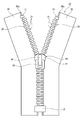
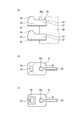
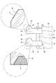
- FIG. 1 It is a surface view explaining 1st Embodiment of the slide fastener which concerns on this invention. It is a figure explaining the fastener element shown in FIG. 1, (a) is the figure which looked at the fastener element from the surface side, (b) is the figure which looked at the fastener element from the upper side, (c) is a fastener element It is the figure which looked at from the lower side. It is an enlarged surface view explaining a pair of fastener element rows in meshing state. It is a figure which expands and demonstrates a part of fastener element shown in FIG. FIG. 5 is a cross-sectional view taken along line AA in FIG. 4.
- the front side is the front side of the paper surface of FIG. 1
- the back side is the back side of the paper surface of FIG. 1
- the upper side is the upper side of the paper surface of FIG.
- the lower side is the lower side with respect to the paper surface of FIG. 1
- the left side is the left side with respect to the paper surface of FIG. 1
- the right side is the right side with respect to the paper surface of FIG.
- the left-right direction of a fastener tape is also called the width direction.
- the up-down direction of a fastener tape is also called a length direction.
- the slide fastener 10 of the present embodiment includes a pair of woven left and right fastener tapes 20 and a pair of left and right fasteners provided along the opposing tape side edges of the pair of left and right fastener tapes 20.
- the upper stopper part 11 provided at the upper end part of the pair of left and right fastener element rows 30 and the lower stopper part 12 provided at the lower end part of the pair of left and right fastener element rows 30 are provided.
- the usage of the slide fastener 10 can include clothes, bags, shoes, industrial materials, etc., but is not limited thereto.
- the upper stopper 11 and the lower stopper 12 are stoppers that stop the slider 40 from sliding.
- a core string is woven into the core portion 20 a simultaneously with the weaving of the fastener tape 20.
- the dimension of the front-and-back direction of this core part 20a is larger than the dimension of the outer side (it is also called the tape part of the fastener tape 20) from the core part 20a, and the core part 20a is enormous as shown in FIG. It has become.
- the fastener element row 30 is composed of a plurality of fastener elements 31, and the fastener elements 31 are made of, for example, red copper, aluminum, nickel, and the like, and are attached to the core portion 20a of the fastener tape 20 by caulking.
- the fastener tape 20 is a woven polyester yarn.
- the fastener element 31 has a base portion 32 attached to the core portion 20 a of the fastener tape 20, extends from the base portion 32 toward the mating fastener tape 20, and meshes with the opposing fastener element 31.
- a meshing head 33 As shown in FIG. 2, the fastener element 31 has a base portion 32 attached to the core portion 20 a of the fastener tape 20, extends from the base portion 32 toward the mating fastener tape 20, and meshes with the opposing fastener element 31.
- a meshing head 33 is shown in FIG. 2, the fastener element 31 has a base portion 32 attached to the core portion 20 a of the fastener tape 20, extends from the base portion 32 toward the mating fastener tape 20, and meshes with the opposing fastener element 31.
- a meshing protrusion 34 is formed on the upper surface of the meshing head 33, and a meshing recess 35 is formed on the lower surface of the meshing head 33. Therefore, as shown in FIG. 3, in the meshed state of the left and right fastener element rows 30, the meshing projection 34 of one fastener element 31 enters the meshing recess 35 of the other fastener element 31 and one fastener element The meshing convex part 34 of the other fastener element 31 enters the meshing concave part 35 of 31.
- the slider 40 includes a body 41, a handle attachment portion 42 provided on the upper surface of the body 41, and a handle 43 attached to the handle attachment portion 42. Then, by moving the slider 40 to the upper stopper 11 side (upper side), the pair of left and right fastener element rows 30 is engaged, and by moving the slider 40 to the lower stopper 12 side (lower side), a pair of left and right fastener elements 30 are engaged. The fastener element rows 30 are separated.
- silica (silicon oxide) S is attached to the surfaces of the left and right fastener tapes 20 and the left and right fastener elements 31 (see FIG. 4), and a softener is attached to the left and right fastener tapes 20.
- Silica S adheres to the entire surface of the base 32 and the meshing head 33 of the fastener element 31.
- Silica is a kind of silicon oxide, and specifically is a substance composed of silicon dioxide (SiO 2 ).
- the silica S and the softening agent are also attached to the core portions 20 a of the left and right fastener tapes 20.
- the upper stopper part 11 and the lower stopper part 12 are attached to the core part 20a to which the silica S is adhered.
- the mounting strength of the upper stopper 11 and the lower stopper 12 is improved. This strength is a sliding strength against a force in the length direction of the fastener tape 20.
- Examples of the silica adhesion treatment for adhering silica include applying an organosilicon compound liquid containing a silane coupling agent mainly composed of silica particles to the fastener tape 20 and the fastener element 31. And let it dry.
- the liquid may be stored in a bathtub and immersed in the bathtub through a fastener chain.
- softening agent examples include cationic, anionic, nonionic, composite, and silicon.
- the silica S is attached to the core portion 20a of the fastener tape 20
- the frictional force between the yarns constituting the vicinity of the core portion 20a is improved, and the core
- the change in the posture of the fastener element 31 attached to the portion 20a can be suppressed and the silica S is attached to the surface of the fastener element 31, the frictional force between the engaged fastener elements 31 is improved and the thrust strength is increased.
- the meshing strength of the fastener element 31 can be improved while maintaining the operability of the slider 40.
- the slide fastener 10 of this embodiment since the silica S adheres to the meshing head 33 of the fastener element 31, the push-up strength of the fastener element 31 can be further improved.
- the fastener tape 20 can be made flexible and the operability of the slider 40 can be improved.
- a slight change in the posture of the fastener element 31 may occur.
- the silica S adheres to the fastener tape 20 the core portion of the woven fastener tape 20 is formed. Since friction occurs between the yarns constituting 20a, it is possible to prevent the fastener tape 20 from becoming too soft while obtaining flexibility by the softening agent. Thereby, the attitude
- the slide fastener 10 of this embodiment since the upper stopper part 11 and the lower stopper part 12 are attached to the core part 20a to which the silica S is adhered, the upper stopper part 11, the lower stopper part 12, and the core part 20a. Silica S is interposed between the upper stopper portion 11 and the lower stopper portion 12, thereby improving the sliding strength.
- the fastener element 31 may be a fastener element 51 shown in FIG.
- the fastener element 51 includes a base 52 attached to the core portion 20 a of the fastener tape 20, and extends from the base 52 toward the mating fastener tape 20 and meshes with the opposing fastener element 51.
- Engaging head 53 As a modification of the present embodiment, the fastener element 31 may be a fastener element 51 shown in FIG. As shown in FIG. 6, the fastener element 51 includes a base 52 attached to the core portion 20 a of the fastener tape 20, and extends from the base 52 toward the mating fastener tape 20 and meshes with the opposing fastener element 51. Engaging head 53.
- a first meshing convex portion 54 is formed on the distal end side of the upper surface of the meshing head 53, and a base 52 is formed from the first meshing convex portion 54 on the upper surface of the meshing head 53.
- a first meshing recess 55 is formed on the side.
- a second meshing convex portion 56 is formed on the distal end side of the lower surface of the meshing head 53, and a second meshing concave portion 57 is formed on the base 52 side of the second meshing convex portion 56 on the lower surface of the meshing head 53. Is formed. Therefore, the meshing head 53 is formed as a vertical object.
- the first meshing convex portion 54 of one fastener element 51 enters the second meshing concave portion 57 of the other fastener element 51
- the second meshing projection 56 of the other fastener element 51 enters the first meshing recess 55 of one fastener element 51
- the second meshing projection 56 of the one fastener element 51 is the first mesh of the other fastener element 51.
- the first meshing protrusion 54 of the other fastener element 51 While entering the meshing recess 55, the first meshing protrusion 54 of the other fastener element 51 enters the second meshing recess 57 of one fastener element 51.
- silica (silicon oxide) S is attached only to the surfaces of the first and second meshing convex portions 54 and 56 of the left and right fastener tapes 20 and the left and right fastener elements 31. is doing.
- silica (silicon oxide) S is attached to the surfaces of the left and right fastener tapes 20 and the left and right fastener elements 31 (see FIG. 4), and the left and right fastener tapes 20.
- the anti-fogging agent and fluorine compound are adhered.
- a predetermined pattern (color) P is printed (colored) on the fastener tape 20, the fastener element 31, and the fastener tape 20 near the fastener element 31 by inkjet.
- the opening tool 13 is provided instead of the bottom stop 12 of the first embodiment.
- the opening tool 13 includes a box bar 14 and a box body 15 provided at the lower end of the right fastener element row 30. , Provided at the lower end portion of the left side fastener element row 30, and a butterfly pin 16 that can be inserted into the box 15.
- the opening tool 13 may be a reverse opening tool that is separable left and right and that can separate the engagement of the fastener element 31 from the lower side.
- the opening tool 13 and the reverse opening tool are also stops.
- the bleeding inhibitor examples include vinyl acrylate, sodium acrylate polymer, starch / acrylic acid graft copolymer cross-linked product, cross-linked polyacrylate, polyamine-based, allylamine-based, acrylic-based, dicyandiamide-based, etc. be able to.
- the anti-bleeding agent improves the fixability of the ink. However, since the anti-bleeding agent has a function of hardening the fibers, the softening agent similar to that in the first embodiment is added to the anti-bleeding agent.
- Fluorine compounds include polypentadecafluorooctyl acrylate, polytrifluoroethyl acrylate, tetrafluoroethylene-hexafluoropropylene copolymer, perfluorolauric acid, polytetrafluoroethylene, perfluoro n-alkyl acrylate, polyfluoride. And vinylidene chloride, pentadecane butylethyl methacrylate, hexafluoropropylene and the like.
- copolymer which consists of 2 or more types of the olefin containing a fluorine atom, the copolymer of the olefin and fluorine monomer containing a fluorine atom, etc. can be mentioned.
- the anti-bleeding agent is attached to the fastener tape 20, so that the inkjet tape can be printed neatly on the fastener tape 20.
- the fastener tape 20 can be made flexible and the operativity of the slider 40 can be improved.
- the fastener tape 20 flexible, there is a possibility that a slight change in the posture of the fastener element 31 may occur.
- the silica S adheres to the fastener tape 20
- the core portion of the woven fastener tape 20 is formed. Since friction occurs between the yarns constituting 20a, it is possible to prevent the fastener tape 20 from becoming too soft while obtaining flexibility by the softening agent. Thereby, the attitude
- the fluorine compound since the fluorine compound is attached to the fastener tape 20, the fluorine compound acts as a water / oil repellent and is ejected when printing on the fastener tape 20 by inkjet. Ink droplets can be prevented from being easily absorbed by the fastener tape 20. For this reason, it is possible to prevent the ejected ink droplets from spreading beyond a desired range, so that inkjet printing on the fastener tape 20 can be performed neatly.
- the fastener tape 20 is dyed with a pattern (including design, decoration, and color in one color).
- a pattern including design, decoration, and color in one color.
- ink is attached by ink jet printing, and then heat treatment is performed to dye the yarn.
- a pattern can also be dye
- the resin layer include polyester and polybutylene terephthalate.
- silica can be directly attached to the meshing head of the metal fastener element, and the resin layer can be formed on the surface of the fastener element other than the meshing head.
- the resin layer can be formed on the surface of the fastener element other than the meshing head.
- the following slide fasteners 1 to 5 (No. 1 to No. 5) were prepared.
- the fastener tape is made of woven polyester yarn, and the fastener element is made of red copper.
- FIG. 9 shows a manufacturing process of the slide fasteners 1 to 5.
- the slide fastener 1 has a fastener element attached to the core of a fastener tape, and corresponds to a normal slide fastener.
- the slide fastener 2 has a fastener element attached to the core portion of the fastener tape after a bleeding inhibitor is adhered to the fastener tape.
- the slide fastener 3 is formed by attaching a bleeding inhibitor and silica to the fastener tape and then attaching a fastener element to the core of the fastener tape. Therefore, silica is not attached to the fastener element.
- the slide fastener 4 is obtained by attaching silica to the fastener tape and the fastener element after attaching the fastener element to the core portion of the fastener tape.
- the slide fastener 5 is obtained by attaching an anti-bleeding agent to the fastener tape, attaching a fastener element to the core portion of the fastener tape, and further attaching silica to the fastener tape and the fastener element. Therefore, it corresponds to the slide fastener of the second embodiment.
- the silica adhesion treatment in the slide fasteners 3 to 4 was performed by applying an organosilicon compound liquid containing a silane coupling agent. More specifically, NC-1020 manufactured by Takamatsu Yushi Co., Ltd., whose main component is silica particles, was used.
- the anti-bleeding agent adhesion treatment in the slide fasteners 2, 3, and 5 was performed by applying a liquid containing a fluorine-based compound so that ink jet printing can be performed with a polyamine resin. Then, it is dried. Note that the bleeding inhibitor is removed by the subsequent reduction treatment, but some components remain on the fastener tape. Moreover, a fluorine-type compound also remains on a fastener tape.
- the reduction treatment here is, for example, hot water washing (80 ° C. to 90 ° C.), or soaping using a soaping aid and soda ash (about 80 ° C.).
- a predetermined load is applied to the left and right fastener tapes of the slide fastener in a state in which the left and right fastener element rows are engaged with each other using a dedicated test device, and the slack of the fastener tapes is applied.
- the left and right fastener tapes are respectively gripped by the left and right grip portions of the test apparatus with the load removed.
- a push-up force is gradually applied to the left and right fastener element rows in the engaged state by a bar-like member from the tape rear surface side toward the front surface side.
- the push-up force is increased, and the magnitude of the push-up force when the right and left fastener element rows are disengaged and the left and right fastener element rows are separated is measured as the push-up strength of the slide fastener.
- a push-up force is applied to the fastener element row, a load of 0.3 kg is applied in the direction away from the vertical direction (length direction) of the fastener tape.
- silica silica
- fluorine-based compound a fluorine-based compound
- a bleeding inhibitor a bleeding inhibitor attached to the slide fastener
- silica silicon oxide
- fluorine fluorine
- the analysis can be performed by energy dispersive X-ray analysis.
- the analysis is preferably performed with a scanning electron microscope attached to an energy dispersive X-ray spectrometer.
- a bleed-inhibiting agent or a softening agent In order to analyze the presence or absence of a bleed-inhibiting agent or a softening agent, it can be determined by performing Soxhlet extraction with a carbon tetrachloride solvent and analyzing the extract.
Landscapes
- Slide Fasteners (AREA)
Description
(1)一対のファスナーテープと、一対のファスナーテープの対向するテープ側縁部に沿ってそれぞれ設けられる一対の芯部と、一対の芯部にそれぞれ取り付けられ、金属製の複数のファスナーエレメントを有する一対のファスナーエレメント列と、を備えるスライドファスナーであって、芯部及びファスナーエレメントの表面にシリカを付着することを特徴とするスライドファスナー。
(2)ファスナーエレメントの噛合頭部にシリカを付着することを特徴とする(1)に記載のスライドファスナー。
(3)一対のファスナーテープに柔軟剤を付着することを特徴とする(1)又は(2)に記載のスライドファスナー。
(4)一対のファスナーテープににじみ防止剤を付着し、少なくともファスナーテープに模様が染色されることを特徴とする(3)に記載のスライドファスナー。
(5)一対のファスナーテープにフッ素系化合物を付着し、少なくともファスナーテープに模様が染色されることを特徴とする(4)に記載のスライドファスナー。
(6)シリカが付着された芯部に止部が取り付けられることを特徴とする(1)~(5)のいずれか1つに記載のスライドファスナー。
まず、図1~図7を参照して、本発明に係るスライドファスナーの第1実施形態について説明する。
次に、図8を参照して、本発明に係るスライドファスナーの第2実施形態について説明する。なお、上記第1実施形態と同一又は同等部分については、図面に同一符号を付してその説明を省略或いは簡略化する。
その他の構成及び作用効果については、上記第1実施形態と同様である。

11 上止部
12 下止部
20 ファスナーテープ
20a 芯部
30 ファスナーエレメント列
31 ファスナーエレメント
32 基部
33 噛合頭部
51 ファスナーエレメント
52 基部
53 噛合頭部
S シリカ
Claims (6)
- 一対のファスナーテープ(20)と、
前記一対のファスナーテープの対向するテープ側縁部に沿ってそれぞれ設けられる一対の芯部(20a)と、
前記一対の芯部にそれぞれ取り付けられ、金属製の複数のファスナーエレメント(31,51)を有する一対のファスナーエレメント列(30)と、を備えるスライドファスナーであって、
前記芯部及び前記ファスナーエレメントの表面にシリカ(S)を付着することを特徴とするスライドファスナー。 - 前記ファスナーエレメント(31,51)の噛合頭部(33,53)にシリカ(S)を付着することを特徴とする請求項1に記載のスライドファスナー。
- 前記一対のファスナーテープ(20)に柔軟剤を付着することを特徴とする請求項1又は2に記載のスライドファスナー。
- 前記一対のファスナーテープ(20)ににじみ防止剤を付着し、少なくとも前記ファスナーテープに模様が染色されることを特徴とする請求項3に記載のスライドファスナー。
- 前記一対のファスナーテープ(20)にフッ素系化合物を付着し、少なくとも前記ファスナーテープに模様が染色されることを特徴とする請求項4に記載のスライドファスナー。
- シリカ(S)が付着された前記芯部(20a)に止部(11,12)が取り付けられることを特徴とする請求項1~5のいずれか1項に記載のスライドファスナー。
Priority Applications (6)
| Application Number | Priority Date | Filing Date | Title |
|---|---|---|---|
| DE112012006174.8T DE112012006174B4 (de) | 2012-03-30 | 2012-03-30 | Reissverschluss |
| JP2014507220A JP5977815B2 (ja) | 2012-03-30 | 2012-03-30 | スライドファスナー |
| CN201280067320.8A CN104053377B (zh) | 2012-03-30 | 2012-03-30 | 拉链 |
| US14/383,615 US9414650B2 (en) | 2012-03-30 | 2012-03-30 | Slide fastener |
| PCT/JP2012/058569 WO2013145257A1 (ja) | 2012-03-30 | 2012-03-30 | スライドファスナー |
| TW102109725A TWI495438B (zh) | 2012-03-30 | 2013-03-19 | zipper |
Applications Claiming Priority (1)
| Application Number | Priority Date | Filing Date | Title |
|---|---|---|---|
| PCT/JP2012/058569 WO2013145257A1 (ja) | 2012-03-30 | 2012-03-30 | スライドファスナー |
Publications (1)
| Publication Number | Publication Date |
|---|---|
| WO2013145257A1 true WO2013145257A1 (ja) | 2013-10-03 |
Family
ID=49258621
Family Applications (1)
| Application Number | Title | Priority Date | Filing Date |
|---|---|---|---|
| PCT/JP2012/058569 Ceased WO2013145257A1 (ja) | 2012-03-30 | 2012-03-30 | スライドファスナー |
Country Status (6)
| Country | Link |
|---|---|
| US (1) | US9414650B2 (ja) |
| JP (1) | JP5977815B2 (ja) |
| CN (1) | CN104053377B (ja) |
| DE (1) | DE112012006174B4 (ja) |
| TW (1) | TWI495438B (ja) |
| WO (1) | WO2013145257A1 (ja) |
Cited By (4)
| Publication number | Priority date | Publication date | Assignee | Title |
|---|---|---|---|---|
| CN105167340A (zh) * | 2015-10-14 | 2015-12-23 | 泉州迪特工业产品设计有限公司 | 一种金属线材及使用该金属线材的拉链 |
| WO2017179213A1 (ja) * | 2016-04-15 | 2017-10-19 | Ykk株式会社 | ファスナーストリンガーの製造方法及びファスナーストリンガー |
| TWI739213B (zh) * | 2019-07-04 | 2021-09-11 | 日商Ykk股份有限公司 | 鏈齒構件及具有拉鏈之製品 |
| WO2022244066A1 (ja) * | 2021-05-17 | 2022-11-24 | Ykk株式会社 | スライドファスナーとその製造方法及びスライドファスナー縫製物品 |
Families Citing this family (14)
| Publication number | Priority date | Publication date | Assignee | Title |
|---|---|---|---|---|
| CN104095353B (zh) * | 2014-07-22 | 2017-08-11 | 福建浔兴拉链科技股份有限公司 | 具有上下牙点的拉链带 |
| CN107072358A (zh) * | 2015-03-06 | 2017-08-18 | Ykk株式会社 | 拉链牙链带的制造方法和缝有该拉链牙链带的面料的制造方法 |
| CN106560259B (zh) * | 2015-12-01 | 2018-12-14 | 福建晋江浔兴拉链科技有限公司 | 金属链牙、链牙成型模具及链牙加工方法 |
| KR102059847B1 (ko) * | 2016-05-06 | 2019-12-27 | 와이케이케이 가부시끼가이샤 | 파스너 엘리먼트, 파스너 엘리먼트의 제조 장치 및 파스너 엘리먼트의 제조 방법 |
| USD800419S1 (en) * | 2016-07-20 | 2017-10-24 | Nike, Inc. | Garment |
| USD825139S1 (en) * | 2016-07-20 | 2018-08-14 | Nike, Inc. | Garment |
| USD814744S1 (en) | 2016-07-20 | 2018-04-10 | Nike, Inc. | Garment |
| CN106761342A (zh) * | 2017-03-06 | 2017-05-31 | 济源市万荣商贸有限公司 | 一种磁吸式汽车防雾霾纱窗 |
| CN106974373B (zh) * | 2017-05-24 | 2023-04-11 | 晋江福兴拉链有限公司 | 一种拉链链带柔化定型设备及其柔化定型方法 |
| CN110089813A (zh) * | 2019-06-03 | 2019-08-06 | 宜兴市德林服饰科技有限公司 | 一种球头形布带筋可变形拉链 |
| CN111441053A (zh) * | 2020-03-25 | 2020-07-24 | 浙江伟星实业发展股份有限公司 | 一种金属拉链部件的着色处理方法和金属拉链 |
| WO2022085099A1 (ja) * | 2020-10-21 | 2022-04-28 | Ykk株式会社 | スライドファスナー |
| CN113425042A (zh) * | 2021-07-21 | 2021-09-24 | 高梵(浙江)信息技术有限公司 | 一种闭口式羽绒服拉链结构 |
| CN113545567B (zh) * | 2021-07-22 | 2023-12-19 | 福建浔兴拉链科技股份有限公司 | 拉链及应用该拉链的物品 |
Citations (4)
| Publication number | Priority date | Publication date | Assignee | Title |
|---|---|---|---|---|
| JP2000041713A (ja) * | 1998-07-31 | 2000-02-15 | Akira Fujishima | 抗菌性ファスニング部品及びその作製方法 |
| JP2004016751A (ja) * | 2002-06-20 | 2004-01-22 | Ykk Corp | 薬剤付きファスナー |
| JP2005344218A (ja) * | 2004-05-31 | 2005-12-15 | Konica Minolta Holdings Inc | 前処理方法 |
| WO2011125176A1 (ja) * | 2010-04-06 | 2011-10-13 | Ykk株式会社 | ファスナーストリンガー及びスライドファスナー |
Family Cites Families (11)
| Publication number | Priority date | Publication date | Assignee | Title |
|---|---|---|---|---|
| US1660192A (en) * | 1926-06-22 | 1928-02-21 | John B Freysinger | Flexible closure |
| US2496946A (en) | 1945-10-09 | 1950-02-07 | G E Prentice Mfg Co | Fastener structure |
| JPH03247306A (ja) * | 1990-02-23 | 1991-11-05 | Kuraray Co Ltd | 成形面フアスナー |
| JPH0424004A (ja) * | 1990-05-21 | 1992-01-28 | Daiichi Seni Kako Kk | 模様付きファスナ、その染色方法及び装置 |
| JPH101814A (ja) * | 1996-06-13 | 1998-01-06 | Mitsubishi Paper Mills Ltd | シャワーキャップ |
| CN2444466Y (zh) * | 2000-10-10 | 2001-08-29 | 谢镇州 | 拉链反光效果装置 |
| TW200302894A (en) * | 2002-02-05 | 2003-08-16 | Y K K Corp | Flame-resistance molded article and fabric product |
| JP5154045B2 (ja) | 2006-09-14 | 2013-02-27 | 日本ゴア株式会社 | 耐摩耗性に優れた布帛、複合布帛、および、繊維製品、ならびに、その製造方法 |
| JP4689631B2 (ja) * | 2007-02-08 | 2011-05-25 | Ykk株式会社 | 液密スライドファスナー並びに液密スライドファスナーの製造方法 |
| TWM396635U (en) * | 2010-07-28 | 2011-01-21 | Ching-Tsun Wang | Improved structure of metal teeth |
| CN202218657U (zh) * | 2011-09-02 | 2012-05-16 | 杭州市余杭实验中学 | 静音拉锁头 |
-
2012
- 2012-03-30 JP JP2014507220A patent/JP5977815B2/ja active Active
- 2012-03-30 CN CN201280067320.8A patent/CN104053377B/zh active Active
- 2012-03-30 WO PCT/JP2012/058569 patent/WO2013145257A1/ja not_active Ceased
- 2012-03-30 DE DE112012006174.8T patent/DE112012006174B4/de active Active
- 2012-03-30 US US14/383,615 patent/US9414650B2/en active Active
-
2013
- 2013-03-19 TW TW102109725A patent/TWI495438B/zh active
Patent Citations (4)
| Publication number | Priority date | Publication date | Assignee | Title |
|---|---|---|---|---|
| JP2000041713A (ja) * | 1998-07-31 | 2000-02-15 | Akira Fujishima | 抗菌性ファスニング部品及びその作製方法 |
| JP2004016751A (ja) * | 2002-06-20 | 2004-01-22 | Ykk Corp | 薬剤付きファスナー |
| JP2005344218A (ja) * | 2004-05-31 | 2005-12-15 | Konica Minolta Holdings Inc | 前処理方法 |
| WO2011125176A1 (ja) * | 2010-04-06 | 2011-10-13 | Ykk株式会社 | ファスナーストリンガー及びスライドファスナー |
Cited By (7)
| Publication number | Priority date | Publication date | Assignee | Title |
|---|---|---|---|---|
| CN105167340A (zh) * | 2015-10-14 | 2015-12-23 | 泉州迪特工业产品设计有限公司 | 一种金属线材及使用该金属线材的拉链 |
| CN105167340B (zh) * | 2015-10-14 | 2021-05-04 | 泉州迪特工业产品设计有限公司 | 一种金属线材及使用该金属线材的拉链 |
| WO2017179213A1 (ja) * | 2016-04-15 | 2017-10-19 | Ykk株式会社 | ファスナーストリンガーの製造方法及びファスナーストリンガー |
| TWI739213B (zh) * | 2019-07-04 | 2021-09-11 | 日商Ykk股份有限公司 | 鏈齒構件及具有拉鏈之製品 |
| US12022920B2 (en) | 2019-07-04 | 2024-07-02 | Ykk Corporation | Element member and slide fastener-attached product |
| WO2022244066A1 (ja) * | 2021-05-17 | 2022-11-24 | Ykk株式会社 | スライドファスナーとその製造方法及びスライドファスナー縫製物品 |
| US12507767B2 (en) | 2021-05-17 | 2025-12-30 | Ykk Corporation | Slide fastener, production method for same, and sewn slide fastener article |
Also Published As
| Publication number | Publication date |
|---|---|
| US9414650B2 (en) | 2016-08-16 |
| JP5977815B2 (ja) | 2016-08-24 |
| TWI495438B (zh) | 2015-08-11 |
| TW201343100A (zh) | 2013-11-01 |
| DE112012006174T5 (de) | 2014-12-11 |
| CN104053377B (zh) | 2016-11-09 |
| DE112012006174B4 (de) | 2018-11-15 |
| CN104053377A (zh) | 2014-09-17 |
| JPWO2013145257A1 (ja) | 2015-08-03 |
| US20150107062A1 (en) | 2015-04-23 |
Similar Documents
| Publication | Publication Date | Title |
|---|---|---|
| JP5977815B2 (ja) | スライドファスナー | |
| JP6399917B2 (ja) | 表皮材止着用クリップ | |
| CN205125270U (zh) | 扣具 | |
| KR102271593B1 (ko) | 이동 안내 장치 및 홈 차폐 유닛 | |
| JP5575976B2 (ja) | 簡易ロック機構を有するスライドファスナー | |
| CN102821639B (zh) | 拉链条以及拉链 | |
| KR101265865B1 (ko) | 슬라이드 파스너 | |
| JP5579276B2 (ja) | ファスナーストリンガー及びファスナーチェーン、並びにファスナーチェーンの製造方法 | |
| WO2016046915A1 (ja) | ファスナーエレメント、ファスナーストリンガー及びスライドファスナー | |
| EP2904922A3 (en) | Slide fastener | |
| JP5989103B2 (ja) | スライドファスナー用スライダー | |
| CN103281926A (zh) | 拉链 | |
| WO2019244321A1 (ja) | 合成皮革及びその製造方法 | |
| CN107072357A (zh) | 拉链用的拉头 | |
| JP2016202761A (ja) | スライドファスナー | |
| JP2024110888A (ja) | オープン両開きファスナーの下止め装置及びその組立て構造 | |
| TWI750390B (zh) | 一種拉鏈牙的樹脂材料表面形成橡膠層的方法以及拉鏈牙的樹脂材料結構 | |
| CN110811084B (zh) | 拉片辅助器具、拉片以及拉链拉头 | |
| JP2011148566A (ja) | エスカレータの移動手摺 | |
| CN105570445B (zh) | 用于换挡机构手柄杆的定位结构 | |
| JP7083025B2 (ja) | エレメント及びスライドファスナー | |
| CN204378090U (zh) | 新型拉链 | |
| IT202100001817A1 (it) | Elemento porta-decorazione per un cursore di una cerniera lampo | |
| CN216019482U (zh) | 扣具 | |
| CN205125701U (zh) | 沙发面套装具及沙发 |
Legal Events
| Date | Code | Title | Description |
|---|---|---|---|
| 121 | Ep: the epo has been informed by wipo that ep was designated in this application |
Ref document number: 12872866 Country of ref document: EP Kind code of ref document: A1 |
|
| ENP | Entry into the national phase |
Ref document number: 2014507220 Country of ref document: JP Kind code of ref document: A |
|
| WWE | Wipo information: entry into national phase |
Ref document number: 14383615 Country of ref document: US |
|
| WWE | Wipo information: entry into national phase |
Ref document number: 112012006174 Country of ref document: DE Ref document number: 1120120061748 Country of ref document: DE |
|
| 122 | Ep: pct application non-entry in european phase |
Ref document number: 12872866 Country of ref document: EP Kind code of ref document: A1 |