WO2013145152A1 - 溶湯容器の炉壁構造及び溶湯容器の炉壁施工方法 - Google Patents
溶湯容器の炉壁構造及び溶湯容器の炉壁施工方法 Download PDFInfo
- Publication number
- WO2013145152A1 WO2013145152A1 PCT/JP2012/058136 JP2012058136W WO2013145152A1 WO 2013145152 A1 WO2013145152 A1 WO 2013145152A1 JP 2012058136 W JP2012058136 W JP 2012058136W WO 2013145152 A1 WO2013145152 A1 WO 2013145152A1
- Authority
- WO
- WIPO (PCT)
- Prior art keywords
- furnace wall
- magnesia
- heat insulating
- insulating material
- carbon
- Prior art date
- Legal status (The legal status is an assumption and is not a legal conclusion. Google has not performed a legal analysis and makes no representation as to the accuracy of the status listed.)
- Ceased
Links
Images

Classifications
-
- C—CHEMISTRY; METALLURGY
- C04—CEMENTS; CONCRETE; ARTIFICIAL STONE; CERAMICS; REFRACTORIES
- C04B—LIME, MAGNESIA; SLAG; CEMENTS; COMPOSITIONS THEREOF, e.g. MORTARS, CONCRETE OR LIKE BUILDING MATERIALS; ARTIFICIAL STONE; CERAMICS; REFRACTORIES; TREATMENT OF NATURAL STONE
- C04B35/00—Shaped ceramic products characterised by their composition; Ceramics compositions; Processing powders of inorganic compounds preparatory to the manufacturing of ceramic products
- C04B35/01—Shaped ceramic products characterised by their composition; Ceramics compositions; Processing powders of inorganic compounds preparatory to the manufacturing of ceramic products based on oxide ceramics
- C04B35/03—Shaped ceramic products characterised by their composition; Ceramics compositions; Processing powders of inorganic compounds preparatory to the manufacturing of ceramic products based on oxide ceramics based on magnesium oxide, calcium oxide or oxide mixtures derived from dolomite
- C04B35/04—Shaped ceramic products characterised by their composition; Ceramics compositions; Processing powders of inorganic compounds preparatory to the manufacturing of ceramic products based on oxide ceramics based on magnesium oxide, calcium oxide or oxide mixtures derived from dolomite based on magnesium oxide
- C04B35/043—Refractories from grain sized mixtures
-
- C—CHEMISTRY; METALLURGY
- C04—CEMENTS; CONCRETE; ARTIFICIAL STONE; CERAMICS; REFRACTORIES
- C04B—LIME, MAGNESIA; SLAG; CEMENTS; COMPOSITIONS THEREOF, e.g. MORTARS, CONCRETE OR LIKE BUILDING MATERIALS; ARTIFICIAL STONE; CERAMICS; REFRACTORIES; TREATMENT OF NATURAL STONE
- C04B35/00—Shaped ceramic products characterised by their composition; Ceramics compositions; Processing powders of inorganic compounds preparatory to the manufacturing of ceramic products
- C04B35/01—Shaped ceramic products characterised by their composition; Ceramics compositions; Processing powders of inorganic compounds preparatory to the manufacturing of ceramic products based on oxide ceramics
- C04B35/013—Shaped ceramic products characterised by their composition; Ceramics compositions; Processing powders of inorganic compounds preparatory to the manufacturing of ceramic products based on oxide ceramics containing carbon
-
- C—CHEMISTRY; METALLURGY
- C21—METALLURGY OF IRON
- C21C—PROCESSING OF PIG-IRON, e.g. REFINING, MANUFACTURE OF WROUGHT-IRON OR STEEL; TREATMENT IN MOLTEN STATE OF FERROUS ALLOYS
- C21C5/00—Manufacture of carbon-steel, e.g. plain mild steel, medium carbon steel or cast steel or stainless steel
- C21C5/28—Manufacture of steel in the converter
- C21C5/42—Constructional features of converters
- C21C5/44—Refractory linings
-
- F—MECHANICAL ENGINEERING; LIGHTING; HEATING; WEAPONS; BLASTING
- F27—FURNACES; KILNS; OVENS; RETORTS
- F27D—DETAILS OR ACCESSORIES OF FURNACES, KILNS, OVENS OR RETORTS, IN SO FAR AS THEY ARE OF KINDS OCCURRING IN MORE THAN ONE KIND OF FURNACE
- F27D1/00—Casings; Linings; Walls; Roofs
- F27D1/0003—Linings or walls
- F27D1/0006—Linings or walls formed from bricks or layers with a particular composition or specific characteristics
-
- C—CHEMISTRY; METALLURGY
- C04—CEMENTS; CONCRETE; ARTIFICIAL STONE; CERAMICS; REFRACTORIES
- C04B—LIME, MAGNESIA; SLAG; CEMENTS; COMPOSITIONS THEREOF, e.g. MORTARS, CONCRETE OR LIKE BUILDING MATERIALS; ARTIFICIAL STONE; CERAMICS; REFRACTORIES; TREATMENT OF NATURAL STONE
- C04B2235/00—Aspects relating to ceramic starting mixtures or sintered ceramic products
- C04B2235/02—Composition of constituents of the starting material or of secondary phases of the final product
- C04B2235/30—Constituents and secondary phases not being of a fibrous nature
- C04B2235/42—Non metallic elements added as constituents or additives, e.g. sulfur, phosphor, selenium or tellurium
- C04B2235/422—Carbon
- C04B2235/424—Carbon black
-
- C—CHEMISTRY; METALLURGY
- C04—CEMENTS; CONCRETE; ARTIFICIAL STONE; CERAMICS; REFRACTORIES
- C04B—LIME, MAGNESIA; SLAG; CEMENTS; COMPOSITIONS THEREOF, e.g. MORTARS, CONCRETE OR LIKE BUILDING MATERIALS; ARTIFICIAL STONE; CERAMICS; REFRACTORIES; TREATMENT OF NATURAL STONE
- C04B2235/00—Aspects relating to ceramic starting mixtures or sintered ceramic products
- C04B2235/02—Composition of constituents of the starting material or of secondary phases of the final product
- C04B2235/30—Constituents and secondary phases not being of a fibrous nature
- C04B2235/42—Non metallic elements added as constituents or additives, e.g. sulfur, phosphor, selenium or tellurium
- C04B2235/422—Carbon
- C04B2235/425—Graphite
-
- C—CHEMISTRY; METALLURGY
- C04—CEMENTS; CONCRETE; ARTIFICIAL STONE; CERAMICS; REFRACTORIES
- C04B—LIME, MAGNESIA; SLAG; CEMENTS; COMPOSITIONS THEREOF, e.g. MORTARS, CONCRETE OR LIKE BUILDING MATERIALS; ARTIFICIAL STONE; CERAMICS; REFRACTORIES; TREATMENT OF NATURAL STONE
- C04B2235/00—Aspects relating to ceramic starting mixtures or sintered ceramic products
- C04B2235/70—Aspects relating to sintered or melt-casted ceramic products
- C04B2235/72—Products characterised by the absence or the low content of specific components, e.g. alkali metal free alumina ceramics
-
- C—CHEMISTRY; METALLURGY
- C04—CEMENTS; CONCRETE; ARTIFICIAL STONE; CERAMICS; REFRACTORIES
- C04B—LIME, MAGNESIA; SLAG; CEMENTS; COMPOSITIONS THEREOF, e.g. MORTARS, CONCRETE OR LIKE BUILDING MATERIALS; ARTIFICIAL STONE; CERAMICS; REFRACTORIES; TREATMENT OF NATURAL STONE
- C04B2235/00—Aspects relating to ceramic starting mixtures or sintered ceramic products
- C04B2235/70—Aspects relating to sintered or melt-casted ceramic products
- C04B2235/96—Properties of ceramic products, e.g. mechanical properties such as strength, toughness, wear resistance
- C04B2235/9607—Thermal properties, e.g. thermal expansion coefficient
Definitions
- the present invention relates to a furnace wall structure of a molten metal container (for example, a converter, a hot metal ladle, a molten steel pot, an electric furnace, etc.) and a furnace wall construction method for a molten metal container.
- a molten metal container for example, a converter, a hot metal ladle, a molten steel pot, an electric furnace, etc.
- the converter which is a molten metal vessel, performs oxygen blowing, it is used in a high-temperature environment, and the refractory used for the furnace wall of the converter cannot be repaired frequently. Therefore, high durability (melting resistance, wear resistance, spall resistance) is required for the refractory, and the thickness is usually about 900 mm.
- magnesia carbon brick MgO—C brick
- This magnesia / carbon brick contains magnesia and has excellent fire resistance at high temperatures, and also contains carbon, so it maintains a constant thermal conductivity, and even when the furnace wall is thick. Excellent properties with spall resistance.
- Patent Document 1 discloses a magnesia / carbon brick to which boron is added
- Patent Document 2 discloses a magnesia / carbon brick to which nickel is added.
- Patent Documents 1 and 2 have a certain effect in extending the life of the refractory of the converter, the environment in which the converter is used, particularly the environment in which the temperature change (temperature gradient) increases in the thickness direction of the furnace wall.
- the temperature change temperature gradient
- a difference in thermal expansion occurs in the refractory when viewed in the thickness direction of the furnace wall, and spall damage occurs in the refractory. Therefore, there is a limit to the life that can be extended, and further life extension has been desired. Even when the temperature fluctuation in the converter was large due to the operating rate of the converter, spall damage was likely to occur due to thermal shock, and the life of the refractory could not be extended sufficiently.
- An object of the present invention is to provide a furnace wall structure for a molten metal container and a method for constructing a molten metal container wall.
- One aspect of the present invention is a furnace wall structure of a molten metal container having a furnace wall lined with magnesia-carbon refractory, comprising an iron skin, a permanent refractory lined on the inner surface of the iron skin, and the permanent wall.
- T thickness dimension
- the position is 0.75 ⁇ T (mm) or more from the position of the inner surface of the magnesia-carbon refractory toward the iron skin and 0.92 ⁇
- the thermal conductivity in the range of 25 ° C. to 300 ° C.
- the said heat insulating material which is below mm is arrange
- the magnesia-carbon refractory may have a carbon content of 0.5% by mass or more and 15% by mass or less.
- Another aspect of the present invention is a furnace wall construction method for a molten metal container including a furnace wall lined with magnesia-carbon refractory, the step of lining a permanent refractory on the inner surface of the iron skin, A step of lining a heat insulating material on the inner surface of the permanent refractory, and a step of lining the magnesia carbon refractory on the inner surface of the heat insulating material; in the step of lining the heat insulating material,
- the thickness dimension excluding the iron skin from the furnace wall is Tmm in millimeters, 0.75 ⁇ T (from the inner surface of the magnesia carbon refractory toward the iron skin mm) and 0.92 ⁇ T or less in the thickness direction range, the thermal conductivity in the range of 25 ° C.
- the molten metal container may be a converter, and the operating rate of the converter may be more than 0% and 70% or less.
- the amount of carbon contained in the magnesia-carbon refractory is 0.5 mass% or more and 15 mass% or less. Also good.
- the rear surface of the magnesia-carbon refractory is located at a position within the range of 0.75 ⁇ T to 0.92 ⁇ T in the thickness direction from the operation surface of the furnace wall. Since a heat insulating material having a thermal conductivity of 0.01 to 0.15 W / (m ⁇ K) is disposed on the side, the temperature gradient in the magnesia-carbon refractory can be reduced in the thickness direction of the furnace wall. Thereby, since the thermal expansion difference of the magnesia-carbon refractory in the thickness direction of the furnace wall can be reduced, the spall damage caused by this can be alleviated. Furthermore, since a heat insulating material having a melting point of 1000 to 1400 ° C.
- magnesia / carbon refractory when the thickness of the refractory is reduced at the end of the life of the magnesia / carbon refractory, the magnesia / carbon refractory is used.
- the heat insulating material can be melted by the heat transmitted through. As a result, since voids can be generated in the region where the heat insulating material was present, it is possible to move magnesia-carbon refractory that thermally expands to the iron skin side, reducing the stress generated on the operating surface side, It can suppress spall damage and dropping of magnesia / carbon refractory to the working surface.
- the magnesia / carbon refractory is not mainly damaged by spall damage. Loss and wear can be the main component. For this reason, the accuracy of the end point determination can be improved, and the life of the magnesia-carbon refractory used for the furnace wall can be extended.
- disappear by oxidation may be reduced conventionally compared with the carbon amount of magnesia carbon refractory being 0.5 mass% or more and 15 mass% or less.
- the carbon amount of magnesia carbon refractory being 0.5 mass% or more and 15 mass% or less.
- the thermal gradient inside the magnesia / carbon brick in the thickness direction of the furnace wall can be reduced by arranging the heat insulating material on the iron skin side of the magnesia / carbon brick, and the heat conduction of the magnesia / carbon brick as before. This is because it is no longer necessary to increase the amount of carbon having the function of improving the rate.
- the converter an example of a molten metal container
- the converter is one of facilities such as an ironworks, and is a furnace dedicated to refining metals such as iron and copper.
- the exterior of the converter is made of steel and the interior is lined with refractory bricks that withstand high heat and impact.
- the shape of the converter is barrel type or pear type.
- a shaft is attached and can rotate freely back and forth. Tilt the furnace to inject hot metal and take out molten steel, and keep the furnace upright during refining.
- FIG. 3 the converter (an example of a molten metal container) of this embodiment is one of facilities such as an ironworks, and is a furnace dedicated to refining metals such as iron and copper.
- the exterior of the converter is made of steel and the interior is lined with refractory bricks that withstand high heat and impact.
- the shape of the converter is barrel type or pear type.
- a shaft is attached and can rotate freely back and forth. Tilt the furnace to inject hot metal and take out
- the furnace wall structure of the molten metal container of the present embodiment is a furnace wall structure of a converter 12 including a furnace wall 11 lined with magnesia / carbon brick (an example of magnesia / carbon refractory) 10.
- a heat insulating material 14 is disposed on the back surface 13 side of the magnesia / carbon brick (MgO—C brick) 10 to extend the life of the magnesia / carbon brick 10.
- MgO—C brick magnesia / carbon brick
- the back surface 13 side of the magnesia / carbon brick 10 is the outside of the furnace, and the opposite side of the inside of the furnace that is the working surface 15 side of the furnace wall 11, that is, the molten steel contact surface (molten metal contact surface) side of the magnesia / carbon brick 10. It is. This will be described in detail below.
- the damage factors of magnesia carbon bricks used for converter wall refractories are generally classified into melting damage, wear, oxidation, and spall damage.
- Wear such as erosion, wear, and oxidation is a steady occurrence and wear rate is relatively stable.
- spall damage is greatly worn (damaged) at once, and damage occurs irregularly.
- the above-mentioned factors are combined to damage the magnesia / carbon brick.
- the spall damage is often limited by the use environment. This spall damage is a phenomenon in which the surface of the furnace wall refractory peels off due to cracks or cracks generated when an excessive thermal shock or temperature gradient is applied to the furnace wall refractory.
- This spall damage has a larger damage thickness per time than other damage factors and has a great influence on the life of the converter.
- spall damage progresses greatly at one time, it is difficult to determine the end point of the life of the converter, and may adversely affect the production plan of the converter.
- magnesia / carbon brick In the material design of this magnesia / carbon brick, generally, when the amount of magnesia is increased in order to improve the corrosion resistance, the thermal conductivity is lowered and the spall resistance is deteriorated. On the other hand, if the amount of carbon is increased in order to improve the spall resistance, the proportion of magnesia blended decreases and the corrosion resistance deteriorates. Thus, the corrosion resistance and the spall resistance are in a contradictory relationship.
- magnesia / carbon brick of low carbon quality (low carbon content: for example, 15 mass% or less) for the furnace wall high carbon quality (high carbon content: for example, 15 mass%). Compared with (super) magnesia carbon brick, the thermal conductivity of the brick is lowered and the temperature gradient in the longitudinal direction (thickness direction of the furnace wall) is increased.
- end point determination refers to, for example, measuring the wear rate of the furnace wall refractory (for example, mm / ch, refractory wear thickness mm for each charge production), and producing by the end point time (end point time) Indicates the number of charges).
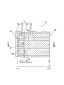
- the heat insulating material 14 is disposed on the furnace wall 11 of the converter 12. That is, a large number of rectangular (or cubic) magnesia bricks 17 (a kind of permanent refractory) are lined on the inner surface of the iron skin 16 of the furnace wall 11 of the converter 12 to cover the entire surface, and the surface of the magnesia brick 17 (furnace) A heat insulating material 14 is attached to the inner surface) to cover the entire surface, and further, a rectangular parallelepiped (or cubic) magnesia carbon brick 10 is covered with a large number of magnesia bricks 17 lined through the heat insulating material 14. ing.
- magnesia brick 17 and the magnesia carbon brick 10 are arranged on both sides in the thickness direction of the furnace wall 11 with the heat insulating material 14 interposed therebetween. That is, the magnesia brick 17 is disposed adjacent to the surface of the heat insulating material 14 on the iron skin 16 side (furnace outer side), and the magnesia carbon brick 10 is disposed on the surface of the heat insulating material 14 on the operating surface 15 side (furnace inner side). Adjacent to each other.
- the magnesia brick 17 described above is a permanent refractory having corrosion resistance, and the thickness of the furnace wall 11 in the thickness direction is, for example, about 50 to 250 mm.
- the permanent refractory is not limited to the magnesia material described above as long as it has corrosion resistance.
- alumina, magnesia alumina spinel, silica, and the like can be applied.
- the refractory may be a brick, and an irregular refractory can also be applied.
- magnesia / carbon brick 10 add carbonaceous raw material to magnesia aggregate, add metal powder or metal compound as needed, and add binders that form carbon bonds such as phenol resin, pitch, tar, etc.
- the brick After being kneaded, the brick is obtained by sequentially performing a molding process and a heat treatment, and the length of the furnace wall 11 in the thickness direction is, for example, about 600 to 1000 mm.
- the wear brick said here means the refractory which contacts a molten metal.
- magnesia source used in the production of this magnesia carbon brick 10
- magnesia source for example, one or more selected from electrofused magnesia, seawater magnesia, natural magnesia, etc. can be used. It is not limited.
- a brick with a high purity is desirable. For example, it is preferable to ensure a purity of 95% by mass or more.
- Carbon-based sources (carbon-based sources) used in the production of magnesia / carbon brick 10 are, for example, natural scale-like graphite, earth-like graphite, artificial graphite, pitch powder, meso-face carbon, anthracite, and carbon black. Although 1 type or 2 or more types chosen can be used, it is not limited only to these.
- the heat insulating material 14 may be made of, for example, a material such as a ceramic fiber mainly composed of glass, silica, or alumina, or a microporous ceramic. This component can lower the thermal conductivity.
- the content of SiO 2 (silica) in the heat insulating material 14 is preferably 40 to 70% by mass.
- SiO 2 can be fine particles having a diameter of about 5 to 30 nm.
- the remaining components are not particularly specified, but can be composed of TiO 2 (titania), ZrSiO 4 , Al 2 O 3 (alumina), or the like.
- the shape of the heat insulating material is preferably a sheet (plate) having a uniform thickness.
- This heat insulating material 14 has a thermal conductivity in the range of room temperature (25 ° C.) to 300 ° C. of 0.01 W / (m ⁇ K) to 0.15 W / (m ⁇ K) and a melting point of 1000 ° C. to 1400 ° C.
- the thickness is 2 mm or more and 10 mm or less.
- this heat insulating material 14 is 0.75 * T or more and 0.92 * T or less thickness position from the operation surface 15 of the furnace wall 11, when the thickness dimension remove
- the magnesia carbon brick is installed at the position of the back surface 13 of the ten.
- the working surface 15 of the furnace wall 11 when the furnace wall refractory is constructed is at a position of “0 ⁇ T”, and the iron skin contact surface 18 (the inner surface of the iron skin 16) of the magnesia brick 17 is “1 ⁇ T”. Position.
- the heat conductivity of the heat insulating material 14 exceeds 0.15 W / (m ⁇ K)
- the heat conductivity is too large, the heat insulating property of the heat insulating material 14 is lowered, and the effect of suppressing the spall damage of the magnesia carbon brick 10 is small.
- the spall damage suppression effect is better as the thermal conductivity of the heat insulating material 14 is smaller for the reasons described above, but the lower limit value of the thermal conductivity of the heat insulating material currently existing in the world is 0.01 W / (m ⁇ K). This is the lower limit.
- the thermal conductivity of the heat insulating material 14 was set to 0.01 W / (m ⁇ K) or more and 0.15 W / (m ⁇ K) or less.
- the upper limit value of the thermal conductivity of the heat insulating material 14 is 0.12 W / (m ⁇ K), and further 0.10 W / (m ⁇ K).
- the melting point of the heat insulating material 14 exceeds 1400 ° C.
- the melting point is too high and the magnesia / carbon brick cannot be melted in the process of wear of the magnesia / carbon brick 10, Cannot be generated.
- the magnesia carbon brick 10 which is thermally expanded and pressed against each other cannot move to the iron skin 16 side, the stress generated on the working surface 15 side of the magnesia carbon brick increases, The magnesia carbon brick 10 falls off to the working surface 15 side.
- the melting point of the heat insulating material 14 is set to 1000 ° C. or more and 1400 ° C. or less, but the lower limit value is more preferably 1100 ° C., more preferably 1200 ° C.
- the thickness of the heat insulating material 14 is less than 2 mm, the thickness of the heat insulating material 14 is too thin. Therefore, when the heat insulating material 14 melts in the process of wear of the magnesia / carbon brick 10, the target is placed on the back surface 13 side of the magnesia / carbon brick 10. The inner gap cannot be formed. For this reason, the ability to relieve the stress generated on the working surface 15 side cannot be exhibited, and the magnesia / carbon brick 10 falls off to the working surface 15 side. On the other hand, when the thickness of the heat insulating material 14 exceeds 10 mm, the thickness of the heat insulating material 14 is too thick.
- the thickness of the heat insulating material 14 is set to 2 mm or more and 10 mm or less, but the upper limit value is more preferably 7 mm, and further preferably 5 mm.
- the installation position of the heat insulating material 14 is a thickness position less than 0.75 ⁇ T from the position of the operating surface 15 (the position of the molten steel contact surface of the magnesia / carbon brick 10) when the furnace wall of the furnace wall 11 is constructed. Since the installation position of the material 14 is too close to the operating surface 15 and the heat insulating material 14 is melted early, the effect of using the heat insulating material 14 does not last for a long time. Further, in this case, the length of the magnesia / carbon brick 10 with respect to the magnesia brick 17 in the thickness direction of the furnace wall 11 is too short (the thickness is too thin), and the performance of the magnesia / carbon brick 10 is sufficiently exhibited. Can not.
- the installation position of the heat insulating material 14 is a thickness position exceeding the position of 0.92 ⁇ T from the position of the working surface 15 of the furnace wall 11, the installation position of the heat insulating material 14 is too close to the iron skin 16.
- the heat insulating function of the heat insulating material 14 disappears in the process of wear of the carbon brick 10, there is a risk that troubles such as red heat of the iron skin 16 occur.
- the installation position of the heat insulating material 14 is set to a thickness position not less than 0.75 ⁇ T and not more than 0.92 ⁇ T from the position of the working surface 15 of the furnace wall 11, and magnesia / carbon brick 10
- the exact installation position of the heat insulating material 14 in the above description is determined with the position in the half of the thickness.
- the carbon content of magnesia carbon brick 10 is within the range of 0.5% by mass or more and 15% by mass or less, which is lower than before.
- the amount of carbon having a function of improving the thermal conductivity is more than 15 mass% and less than 50 mass%.
- the heat insulating material 14 is disposed on the iron skin 16 side of the magnesia / carbon brick 10, the temperature gradient in the longitudinal direction can be reduced regardless of the amount of carbon mixed in the magnesia / carbon brick 10.
- the carbon content of magnesia-carbon brick 10 can be reduced to 15% by mass or less, which is lower than before.
- the carbon content of magnesia carbon brick 10 may be a conventional amount (over 15% by mass). In this case, it is possible to improve the melt resistance by reducing the amount of carbon that is easily oxidized and lost.
- the lower limit of the carbon content is set to 0.5% by mass because the binder (binder: phenol resin, for example) blended in the production of magnesia carbon brick 10 remains in the brick as residual carbon. This is because it cannot be completely removed. That is, since the amount corresponding to this remaining amount is 0.5 mass%, this was set as the lower limit value of the carbon amount.
- the carbon content of magnesia / carbon brick 10 is set to 0.5% by mass or more and 15% by mass or less.
- the upper limit value is set. Is more preferably 13 mass%.
- the furnace wall construction method of the molten metal container in this embodiment is demonstrated, referring FIG. First, a large number of cuboid magnesia bricks 17 are lined on the inner wall surface 16a of the iron shell 16 through the joints without gaps. Next, a plurality of sheet-like heat insulating materials 14 are bonded to the furnace inner surface 17a of the lined magnesia brick 17 so that no gap is generated between the heat insulating materials 14 adjacent to each other. A large number of magnesia / carbon bricks 10 having a rectangular parallelepiped shape are lined on the furnace inner surface 14a of the heat insulating material 14 bonded to the furnace inner surface 17a of the magnesia brick 17 without a gap. At this time, the magnesia / carbon brick 10 is lined so that the longitudinal direction thereof matches the thickness direction of the furnace wall 11 (the radial direction of the converter 12).
- the above-described heat insulating material 14 is located in the thickness direction position not less than 0.75 ⁇ T and not more than 0.92 ⁇ T from the position of the working surface 15 of the furnace wall 11, and on the back surface 13 of the magnesia carbon brick 10. It is installed in a thickness range of 2 mm or more and 10 mm or less.
- the position in the thickness direction in the furnace wall 11 when installing the heat insulating material 14 is the ratio of the length in the thickness direction of the magnesia brick 17 and the length in the thickness direction of the magnesia / carbon brick 10 in the thickness direction. Set by adjusting.
- the magnesia carbon brick 10 a conventional brick having a carbon content of more than 15% by mass can be used.
- the carbon content is 0.5 lower than that of the conventional brick.
- a brick having a mass% of 15% by mass or less can be used. As a result, it is possible to improve the erosion resistance by reducing the amount of carbon that is easily oxidized and lost.
- the operating conditions etc. of the converter 12 used as the installation object of the heat insulating material 14 are not specifically limited, the converter 12 with an operation rate exceeding 0 and 70% or less is the effect of this embodiment. Can be obtained more prominently.
- the operating rate of this converter 12 is calculated
- Operation rate of converter 12 (%) average steelmaking time (minute / ch) ⁇ number of production charges (ch / month) / calendar time (minute / month) ⁇ 100 (1)
- the steelmaking time is the time per charge required for the production of steel (charge may be referred to as heat). Specifically, from scrap input to hot metal charging, blowing, steel extraction, waste It is the total time until. And the average value of this total time is used as average steelmaking time (fraction per unit charge) in said Formula (1).
- the upper limit of the operating rate of the converter 12 is 70%, more preferably 60%.
- the lower limit of the operating rate of the converter 12 may be 30% or more as a general value. In this case, the magnesia carbon brick 10 that is a refractory can have a long life even in a usage environment in which spall damage occurs or in a situation where the fluctuating temperature in the molten metal container is likely to cause spall damage.
- heat insulating material 14 “Porexotherm WDS (registered trademark)” manufactured by Porextherm Damstoff GmbH was used.
- the material is a microporous molded body mainly composed of fumed silica.
- This heat insulating material 14 is a sheet of 1000 mm in length and 500 mm in width (thickness is selected from four types of 1, 2, 10, and 12 mm), and in use, it is bonded to permanent bricks.
- the heat insulating materials 14 adjacent to each other were used so as not to cause a gap. Further, a magnesia / carbon-based wear brick having a carbon content of 13% by mass was used.
- the “iron skin temperature at the time of furnace stop” in Table 1 is an outer surface temperature of the iron skin 16 at a portion where the wear brick is most damaged and thinned, or a portion where the permanent brick is exposed.
- the wear rate is the damage thickness of the wear brick per charge (ch).
- the temperature of the iron skin at the time of stopping the furnace was set to be 550 ° C. or higher because there was a risk of troubles such as red heat of the iron skin 16 if the temperature became too high.
- the wear rate is the average damage thickness per charge of 1 to 500 charges, which is the first half of the usage period (first half of operation), and the average per charge of 2500 to 3000 charges, which is the second half of the usage period (second half of operation). It is shown separately from the damage thickness. From the viewpoint of extending the life based on past results, this wear rate was determined to be 0.30 (mm / charge) or higher, regardless of the first half or second half of the usage period.
- the installation position of the heat insulating material 14 is set in the appropriate range (0.75 ⁇ T to 0.92 ⁇ T), respectively. This is the result of setting the installation position of the heat insulating material 14 outside the appropriate range.
- other conditions of the heat insulating material 14, namely, thermal conductivity (0.02 (W / (m ⁇ K))), melting point (1400 ° C.), and thickness (2 mm) are within the appropriate ranges described above.
- the operating rate of Converter A was unified at 70% or less.
- Examples 2 and 3 are the results of setting the thermal conductivity of the heat insulating material 14 within the appropriate range (0.01 to 0.15 (W / (m ⁇ K))), respectively, Comparative Example 3 is a result of setting the thermal conductivity of the heat insulating material 14 outside the appropriate range.
- the other conditions of the heat insulating material 14, that is, the installation position (0.92 ⁇ T), the melting point (1400 ° C.), and the thickness (2 mm) in the thickness direction of the furnace wall are set within the appropriate ranges described above.
- the operating rate of the converter A was unified to 70% or less.
- the thermal conductivity of the heat insulating material 14 is within an appropriate range (Example 2: 0.02 (W / (m ⁇ K)), Example 3: 0.15 ( By setting to (W / (m ⁇ K))), it was confirmed that the life of the wear brick can be extended in the first half and the second half of the period of use.
- Comparative Example 3 since the thermal conductivity was too high (0.20 (W / (m ⁇ K))), in the first half of the period of use, the heat insulating property of the heat insulating material 14 was deteriorated, and the spall damage of the wear brick The suppression effect was reduced, and the life of the wear brick could not be extended.
- Example 2 is a result of setting the melting point of the heat insulating material 14 within the above-described appropriate range (1000 to 1400 ° C.), while Comparative Example 4 sets the melting point of the heat insulating material 14 outside the appropriate range. It is the result.
- the other conditions of the heat insulating material 14, ie, the installation position (0.92 ⁇ T), the thermal conductivity (0.02 (W / (m ⁇ K))), and the thickness (2 mm) were described above. It was set within an appropriate range, and the operating rate of Converter A was unified to 70% or less.
- Example 2 it was confirmed that by setting the melting point of the heat insulating material 14 within an appropriate range (1400 ° C.), the life of the wear brick can be extended in the first half and the second half of the usage period.
- the wear brick fell off to the operating surface 15 side because the melting point of the heat insulating material 14 was too high (1500 ° C.), and the heat insulating material 14 could not be melted in the wear brick wear process. This is probably because a gap could not be generated on the back side, and as a result, the stress generated on the working surface 15 side of the wear brick could not be relieved. For this reason, the wear brick which thermally expands cannot move to the iron skin 16 side, but falls off to the operating surface 15 side, and the life cannot be extended.
- Examples 2 and 4 are the results of setting the thickness of the heat insulating material 14 within the above-described appropriate range (2 to 10 mm), while Comparative Examples 5 and 6 have the thickness of the heat insulating material 14 set respectively. This is the result set outside the proper range.
- other conditions of the heat insulating material 14, that is, the installation position (0.92 ⁇ T), the thermal conductivity (0.02 (W / (m ⁇ K))), and the melting point (1400 ° C.) are respectively The operating rate of the converter A was unified to 70% or less.
- Comparative Example 6 since the thickness of the heat insulating material 14 is too thick (12 mm), the inner width of the gap formed when the heat insulating material 14 is melted is too wide, and the structure of the wear brick is loosened. The brick fell to the working surface 15 side. For this reason, neither of Comparative Examples 5 and 6 was able to extend the life of the wear brick.
- Example 2 is a result when the operating rate of the converter A is 70% or less
- Example 5 is a result when the operating rate of the converter A is more than 70%.
- Comparative Examples 7 and 8 are not provided with the heat insulating material 14, and Comparative Example 7 is a result when the operating rate of the converter 12 is 70% or less.
- Comparative Example 8 is the result of the converter 12 This is the result when the operating rate of the system is over 70%.
- the lifetime of the wear brick could not be extended.
- the operating rates of the converters A and B shown in FIG. 2A are more than 0% and 70% or less, that is, when the operating rates of the converters A and B are low, the temperature fluctuation in the converter 12 increases.
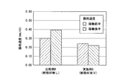
- the wear rate of the wear brick is 0.1 (mm / charge) or more in both the first half and the second half of the usage period (that is, , First half: 0.1 (mm / charge), second half: 0.19 (mm / charge)), and the effect of extending the life of the wear brick by the heat insulating material 14 was remarkable.
- the present invention has been described with reference to the embodiments.
- the present invention is not limited to the configurations described in the above-described embodiments, and is within the scope of the matters described in the claims.
- Other embodiments and modifications that can be considered in the above are also included.
- a case where the furnace wall structure of a molten metal container and the method of constructing a molten metal container wall according to the present invention are configured by combining some or all of the above-described embodiments and modifications are also included in the scope of the present invention. .
- the converter 12 which is a molten metal container was demonstrated, it is not limited only to this, This invention is applied to other molten metal containers, for example, a hot metal ladle, a molten steel pan, an electric furnace, etc. You may apply.
- the furnace wall structure of the molten metal container that can extend the life of the refractory even in a use environment where spall damage occurs or in a situation where the temperature fluctuation in the molten metal container is large and the spall damage is likely to occur.
- the furnace wall construction method of a molten metal container can be provided.
Landscapes
- Engineering & Computer Science (AREA)
- Chemical & Material Sciences (AREA)
- Ceramic Engineering (AREA)
- Manufacturing & Machinery (AREA)
- Materials Engineering (AREA)
- Organic Chemistry (AREA)
- Structural Engineering (AREA)
- Metallurgy (AREA)
- Mechanical Engineering (AREA)
- General Engineering & Computer Science (AREA)
- Furnace Housings, Linings, Walls, And Ceilings (AREA)
- Carbon Steel Or Casting Steel Manufacturing (AREA)
Abstract
Description
本発明の一態様は、マグネシア・カーボン耐火物が内張りされた炉壁を備える溶湯容器の炉壁構造であって、鉄皮と、この鉄皮の内面に内張りされたパーマ耐火物と、このパーマ耐火物の内面に内張りされた断熱材と、この断熱材の内面に内張りされた前記マグネシア・カーボン耐火物とを備え;前記炉壁を縦断面視して、前記炉壁から前記鉄皮を除いた厚み寸法を、ミリメートル単位でT(mm)とした場合に、前記マグネシア・カーボン耐火物の内面の位置から前記鉄皮に向かって0.75×T(mm)の位置以上かつ0.92×Tの位置以下の厚み方向範囲内の位置に、25℃~300℃の範囲での熱伝導率が0.01W/(m・K)以上0.15W/(m・K)以下で、融点が1000℃以上1400℃以下で、厚みが2mm以上10mm以下である前記断熱材が配置されている。
更に、断熱材に、融点が1000~1400℃、厚みが2~10mmのものを使用するため、マグネシア・カーボン耐火物の寿命末期に耐火物厚みが薄くなった場合において、マグネシア・カーボン耐火物を介して伝わる熱により断熱材を溶融できる。これにより、断熱材が存在した領域に空隙を発生させることができるため、熱膨張するマグネシア・カーボン耐火物の鉄皮側への移動が可能となり、稼動面側に発生する応力を低下させて、スポール損傷やマグネシア・カーボン耐火物の稼動面側への脱落を抑制できる。
従って、スポール損傷が発生する使用環境であっても、また溶湯容器内の温度変動が大きくスポール損傷が発生し易い状況でも、マグネシア・カーボン耐火物の損傷をスポール損傷が主体のものではなく、溶損や摩耗が主体のものにできる。このため、終点判定の精度向上が図れ、炉壁に使用するマグネシア・カーボン耐火物の長寿命化が図れる。
図3に示すように、本実施形態の転炉(溶湯容器の一例)は、製鉄所等の設備の1つで、鉄や銅などの金属精錬専用の炉である。転炉の外部は、鋼鉄で作られていて、内部は高熱や衝撃に耐える耐火れんがで内張りされている。転炉の形は、樽型やセイヨウナシ型である。軸が取り付けられていて、前後に自由に回転できる。溶銑の注入や溶鋼の取り出しは炉を傾けて、精錬時は炉を立てた状態で使用する。
図1に示すように、本実施形態の溶湯容器の炉壁構造は、マグネシア・カーボンれんが(マグネシア・カーボン耐火物の一例)10が内張りされた炉壁11を備える転炉12の炉壁構造であり、マグネシア・カーボンれんが(MgO-Cれんが)10の背面13側に断熱材14を配置して、マグネシア・カーボンれんが10の長寿命化を図るものである。なお、マグネシア・カーボンれんが10の背面13側とは炉外側であり、炉壁11の稼動面15側、即ちマグネシア・カーボンれんが10の溶鋼接触面(溶湯接触面)側である炉内側の反対側である。以下、詳しく説明する。
実使用環境においては、前述の各要因が複合してマグネシア・カーボンれんがが損傷するが、その中でもスポール損傷は、使用環境に律速される場合も多い。
このスポール損傷は、炉壁耐火物に過度の熱衝撃や温度勾配が加わった場合に生じた亀裂や割れにより、炉壁耐火物の表面が剥離する現象である。このスポール損傷は、他の損傷要因に比べ、1回あたりの損傷厚みが大きく、転炉の寿命に与える影響も大きい。加えて、スポール損傷は、損傷が一度に大きく進行することから、転炉の寿命の終点判定を難しくし、転炉の生産計画に悪影響を及ぼすこともある。
ここで、耐食性向上を目的に、低カーボン質(低炭素量:例えば、15質量%以下)のマグネシア・カーボンれんがを炉壁に使用する場合、高カーボン質(高炭素量:例えば、15質量%超)のマグネシア・カーボンれんがと比べ、れんがの熱伝導率が低下し、その長手方向(炉壁の厚み方向)の温度勾配が大きくなる。
一般的に、れんがの損傷がスポール損傷主体の場合、溶損主体の場合と比べて、れんがの損耗速度が大きくなる(れんがの残厚の減少スピードが大きい)ことに加え、終点判定が困難になる。一般に、炉壁耐火物の損傷が進行し、パーマ耐火物が露出した時点で転炉寿命が終点に達したと判断する場合が多い。この終点に達した後に炉壁耐火物を更新する必要があるが、炉壁耐火物更新には長期間の準備が必要であり、終点の時期を精度高く予測する必要がある(終点判定)。また突然に終点が到来すると予定した生産が実行できないため、この点でも終点を精度高く予測する必要がある。
なお、ここで言う終点判定とは、例えば炉壁耐火物の損耗速度(例えばmm/ch、1チャージ生産する都度の耐火物損耗厚さmm)を測定し、終点時期(終点時期までに生産できるチャージ数)を予測することを示す。
また、マグネシア・カーボンれんが10の製造に用いられる炭素系ソース(炭素系源)は、例えば、天然の鱗状黒鉛、土状黒鉛、人造黒鉛、ピッチ粉、メゾフェースカーボン、無煙炭、及びカーボンブラック等から選ばれる1種又は2種以上を使用できるが、これらのみに限定されるものではない。
この断熱材14は、常温(25℃)~300℃の範囲での熱伝導率が0.01W/(m・K)以上0.15W/(m・K)以下、融点が1000℃以上1400℃以下、厚みが2mm以上10mm以下のものである。そして、この断熱材14は、炉壁11から鉄皮16を除いた厚み寸法をTとした場合に、炉壁11の稼動面15から0.75×T以上0.92×T以下の厚み位置で、かつマグネシア・カーボンれんが10の背面13の位置に設置されている。なお、炉壁11の炉壁耐火物施工時の稼動面15は、「0×T」の位置となり、マグネシアれんが17の鉄皮接触面18(鉄皮16内面)は、「1×T」の位置となる。
このため、熱膨張して押し合い圧し合いするマグネシア・カーボンれんが10が鉄皮16側へ移動できなくなるため、マグネシア・カーボンれんが10の稼動面15側に発生する応力が上昇して、スポール損傷や、マグネシア・カーボンれんが10の稼動面15側への脱落が発生する。
一方、転炉のように高温環境で使用する溶湯容器に常用される断熱材の融点の下限値は通常1000℃であるので、これを断熱材14の下限値とした。
以上のことから、断熱材14の融点を、1000℃以上1400℃以下としたが、下限値を1100℃、更には1200℃とすることがより好ましい。
一方、断熱材14の厚みが10mmを超える場合、断熱材14の厚みが厚過ぎるため、マグネシア・カーボンれんが10の損耗過程で断熱材14が溶融する際に、マグネシア・カーボンれんが10の背面13側に大きな空隙が形成され、マグネシア・カーボンれんが10の稼動面15側への脱落が発生する。
以上のことから、断熱材14の厚みを、2mm以上10mm以下としたが、上限値を7mm、更には5mmとすることがより好ましい。
一方、断熱材14の設置位置が炉壁11の稼動面15の位置から0.92×Tの位置を超える厚み位置の場合、断熱材14の設置位置が鉄皮16に近づき過ぎるため、マグネシア・カーボンれんが10の損耗過程で断熱材14の断熱機能が消失した際に、鉄皮16の赤熱等のトラブルに至る恐れがある。
以上のことから、断熱材14の設置位置を、炉壁11の稼動面15の位置から0.75×Tの位置以上0.92×Tの位置以下の厚み位置で、かつマグネシア・カーボンれんが10の背面13の位置としたが、下限値を0.80×Tの位置、更には0.85×Tの位置とすることがより好ましい。なお、以上の説明における断熱材14の厳密な設置位置は、その厚みの半分における位置をもって定める。
以上のことから、マグネシア・カーボンれんが10の炭素量を、0.5質量%以上15質量%以下としたが、マグネシア・カーボンれんが10の耐溶損性の更なる向上を図るためには、上限値を13質量%とすることがより好ましい。
なお、上記した断熱材14は、転炉の炉壁全体(炉内壁面の全面)にわたって設置することが好ましいが、特にスポール損傷が発生し易い領域(例えば、出鋼側)のみに、部分的に設置してもよい。
まず、鉄皮16の炉内側内壁面16aに、直方体のマグネシアれんが17を、目地を介して隙間なく多数内張りする。
次に、この内張りしたマグネシアれんが17の炉内側表面17aに、シート状の複数枚の断熱材14を、互いに隣り合う断熱材14の間に隙間が生じないように貼り合わせる。そして、直方体形状を有する多数のマグネシア・カーボンれんが10を、マグネシアれんが17の炉内側表面17aに貼り合わせた断熱材14の炉内側表面14aに、隙間なく多数内張りする。このとき、マグネシア・カーボンれんが10の長手方向を炉壁11の厚み方向(転炉12の径方向)に合わせるように内張りする。
ここで、マグネシア・カーボンれんが10には、炭素量が15質量%超の従来のれんがを使用できるが、炉壁11に断熱材14を設置することで、炭素量が従来よりも低い0.5質量%以上15質量%以下のれんがを使用でき、その結果、酸化消失し易い炭素量を減ずることによる耐溶損性の向上が可能となる。
この転炉12の稼動率は、以下の式(1)で求められる。
転炉12の稼動率(%)=平均製鋼時間(分/ch)×生産チャージ数(ch/月)/暦時間(分/月)×100・・・(1)
なお、製鋼時間とは、鋼の製造に要する1チャージ(チャージをヒートと称する場合あり)あたりの時間であり、具体的には、スクラップ投入から、溶銑装入、吹錬、出鋼、排滓までの合計時間である。そして、この合計時間の平均値を、上記の式(1)における平均製鋼時間(単位チャージ当たりの分数)として用いている。
一方、上記した理由から、転炉12の稼動率が低くなるに伴い、転炉12炉内の温度変動が大きくなり、本実施形態の効果が顕著となるため、転炉12の稼動率の下限を0%超としたが、一般的な値として30%以上としてもよい。
この場合、スポール損傷が発生する使用環境であっても、また溶湯容器内の温度変動が大きくてスポール損傷が発生し易い状況でも、耐火物であるマグネシア・カーボンれんが10の長寿命化が図れる。
ここでは、前記断熱材14を設置した炉壁構造を備える転炉Aと、前記断熱材14を設置しない炉壁構造を備える転炉Bとを使用して、実機調査を行った。
具体的には、転炉Aでは、断熱材14を設置した炉壁構造を、転炉12の鉄皮16の内側に、前記マグネシアれんが17としてマグネシア質のパーマネントれんが(厚み:65~230mm)、断熱材14、及び前記マグネシア・カーボンれんが10としてマグネシア・カーボン質のウェアれんが(厚み:720~990mm)を順次設けた構造とした。その結果を示すものが、実施例1~5及び比較例1~6である。
一方、転炉Bでは、断熱材14を設置しない炉壁構造を、前記鉄皮16の内側に、マグネシア質のパーマネントれんが(厚み:114mm)とマグネシア・カーボン質のウェアれんが(厚み:900mm)とを順次設けた構造とした。その結果を示すものが、比較例7,8である。
また、マグネシア・カーボン質のウェアれんがには、炭素量が13質量%のものを使用した。そして、転炉Aではこのマグネシア・カーボン質のウェアれんがを、転炉Aでは断熱材14の表面に設置して使用した。一方、転炉Bでは、マグネシア・カーボン質のウェアれんがを、パーマネントれんがの表面に設置して使用した。
表1に、実機調査の条件と、得られた鉄皮温度及び炉壁寿命の結果を、それぞれ示す。なお、同表1における実施例1~5及び比較例1~8の詳細内容については後述する。
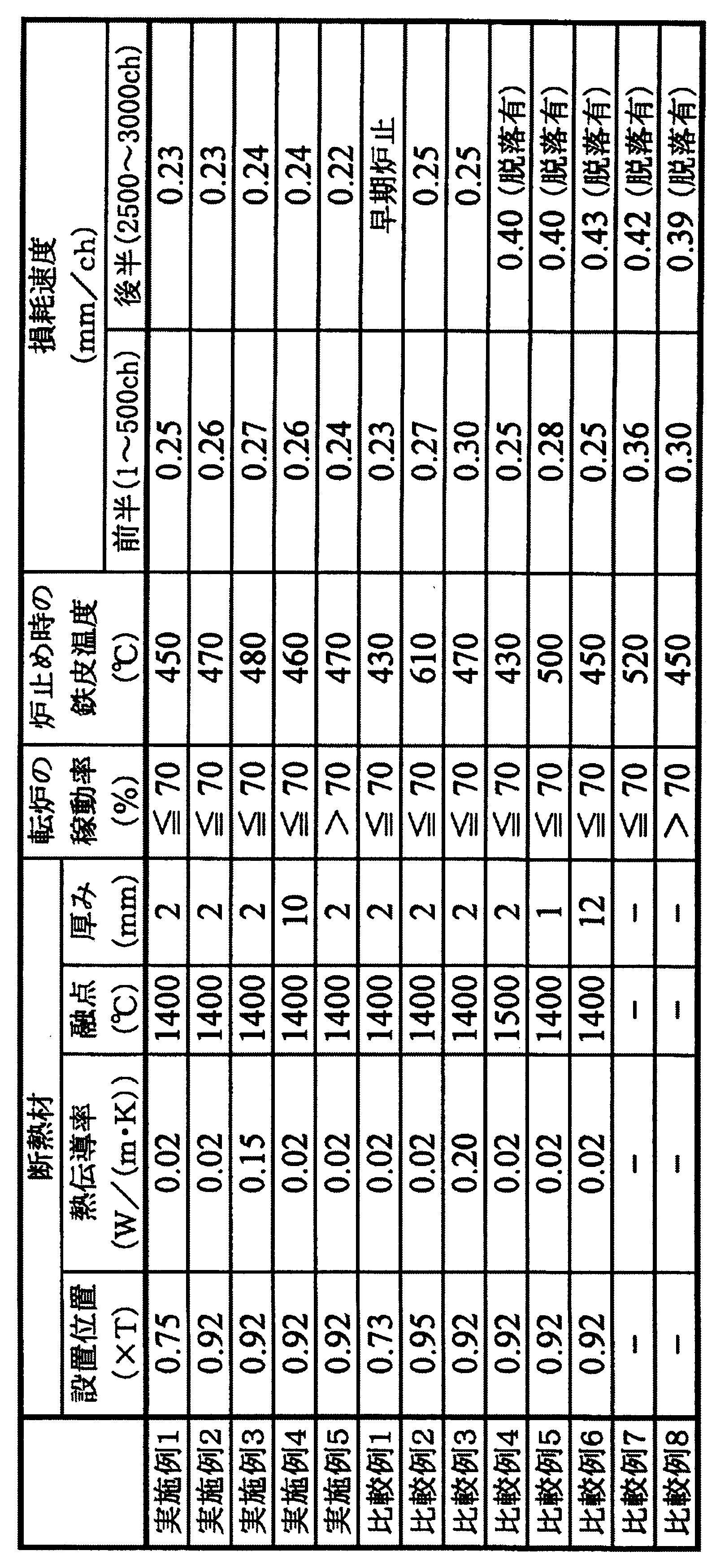
ここで、炉止め時の鉄皮温度は、温度が高くなり過ぎると鉄皮16の赤熱等のトラブルに至る恐れがあることから、550℃以上を不合格とした。
また、損耗速度は、使用期間の前半(稼動前半)である1~500チャージの1チャージあたりの平均損傷厚みと、使用期間の後半(稼動後半)である2500~3000チャージの1チャージあたりの平均損傷厚みとに区別して示している。この損耗速度は、過去の実績に基づいた長寿命化の観点から、使用期間の前半、後半に関わらず、0.30(mm/チャージ)以上を不合格とした。
この実施例1、2は、断熱材14の設置位置を、それぞれ前記した適正範囲(0.75×T~0.92×T)内に設定した結果であり、一方、比較例1、2は、断熱材14の設置位置を、それぞれ適正範囲外に設定した結果である。
なお、断熱材14の他の条件、即ち、熱伝導率(0.02(W/(m・K)))、融点(1400℃)、及び厚み(2mm)は、それぞれ前記した適正範囲内に設定し、転炉Aの稼動率は70%以下で統一した。
一方、比較例1では、断熱材14の設置位置が炉壁11の稼動面15に近づき過ぎて(0.73×T)、断熱材14が早期に溶融してパーマネントれんがが露出するに至り、早期に炉止めを行わなければならず、ウェアれんがの長寿命化が図れなかった。また、比較例2では、断熱材14の設置位置が鉄皮16に近づき過ぎるため(0.95×T)、ウェアれんがの損耗過程で断熱材14の断熱機能が消失した際に、鉄皮温度が上昇して、鉄皮16の赤熱等のトラブルに至る恐れがあった。
この実施例2、3は、断熱材14の熱伝導率を、それぞれ前記した適正範囲(0.01~0.15(W/(m・K)))内に設定した結果であり、一方、比較例3は、断熱材14の熱伝導率を、適正範囲外に設定した結果である。
なお、断熱材14の他の条件、即ち、炉壁の厚み方向の設置位置(0.92×T)、融点(1400℃)、及び厚み(2mm)は、それぞれ前記した適正範囲内に設定し、転炉Aの稼動率は70%以下に統一した。
一方、比較例3では、熱伝導率が大き過ぎたため(0.20(W/(m・K)))、使用期間の前半において、断熱材14の断熱性が低下し、ウェアれんがのスポール損傷抑制効果が小さくなり、ウェアれんがの長寿命化が図れなかった。なお、使用期間の後半においては、ウェアれんがの損耗過程で断熱材14が溶融する際に、ウェアれんがの背面側に目標とする内幅の隙間を形成でき、稼動面15側に発生する応力の緩和能力を発揮できたため、ウェアれんがの稼動面15側への脱落を抑制できた。しかし、使用期間の前半でウェアれんがの損耗速度が大きかったため、使用期間の全体では、ウェアれんがの長寿命化が図れなかった。
この実施例2は、断熱材14の融点を、前記した適正範囲(1000~1400℃)内に設定した結果であり、一方、比較例4は、断熱材14の融点を、適正範囲外に設定した結果である。
なお、断熱材14の他の条件、即ち、設置位置(0.92×T)、熱伝導率(0.02(W/(m・K)))、及び厚み(2mm)は、それぞれ前記した適正範囲内に設定し、転炉Aの稼動率は70%以下に統一した。
実施例2から明らかなように、断熱材14の融点を適正範囲内(1400℃)に設定することで、使用期間の前半及び後半においてウェアれんがの長寿命化が図れることを確認できた。
一方、比較例4でウェアれんがが稼動面15側へ脱落したのは、断熱材14の融点が高過ぎて(1500℃)、ウェアれんがの損耗過程で断熱材14を溶融できず、ウェアれんがの背面側に隙間を生成できず、その結果としてウェアれんがの稼動面15側に発生する応力を緩和できなかったためと考えられる。このため、熱膨張するウェアれんがが鉄皮16側へ移動できずに稼動面15側へ脱落し、長寿命化が図れなかった。
この実施例2、4は、断熱材14の厚みを、それぞれ前記した適正範囲(2~10mm)内に設定した結果であり、一方、比較例5、6は、断熱材14の厚みを、それぞれ適正範囲外に設定した結果である。
なお、断熱材14の他の条件、即ち、設置位置(0.92×T)、熱伝導率(0.02(W/(m・K)))、及び融点(1400℃)は、それぞれ前記した適正範囲内に設定し、転炉Aの稼動率は70%以下に統一した。
一方、比較例5では、断熱材14の厚みが薄過ぎるため(1mm)、ウェアれんがの損耗過程で断熱材14が溶融する際に形成される隙間の内幅が狭過ぎて、稼動面15側に発生する応力の緩和能力を発揮できず、ウェアれんがの稼動面15側への脱落が発生した。また、比較例6では、断熱材14の厚みが厚過ぎるため(12mm)、断熱材14が溶融する際に形成される隙間の内幅が広過ぎて、ウェアれんがの構造に緩みが生じ、ウェアれんがの稼動面15側への脱落が発生した。このため、比較例5、6のいずれも、ウェアれんがの長寿命化が図れなかった。
この実施例2、5は、断熱材14の各条件、即ち炉壁の厚み方向の設置位置(0.92×T)、熱伝導率(0.02(W/(m・K)))、融点(1400℃)、及び厚み(2mm)を、それぞれ前記した適正範囲内に設定している。なお、実施例2は転炉Aの稼動率を70%以下とした場合の結果であり、実施例5は転炉Aの稼動率を70%超とした場合の結果である。
一方、比較例7、8は、いずれも断熱材14を設置しておらず、比較例7は転炉12の稼動率を70%以下とした場合の結果であり、比較例8は転炉12の稼動率を70%超とした場合の結果である。なお、比較例7、8はいずれも断熱材14を用いていないため、ウェアれんがの長寿命化が図れなかった。
一方、図2Bに示す、転炉A,Bの稼動率が70%超の場合、即ち、転炉12の稼動率が高い場合、転炉12炉内の温度変動が小さくなる。このため、断熱材14を設置した場合は、断熱材14を設置しない場合と比べて、使用期間の前半と後半のいずれも、ウェアれんがの損耗速度が良好となったが、使用期間の前半については、転炉の稼動率が低い場合よりも改善代が小さかった(0.06(mm/チャージ))。
従って、断熱材14を設置した効果は、転炉12の稼動率が低い場合に、より顕著になることが分かった。
また、前記実施形態においては、溶湯容器である転炉12について説明したが、これのみに限定されるものではなく、他の溶湯容器、例えば、溶銑鍋、溶鋼鍋、電気炉等に本発明を適用してもよい。
11:炉壁
12:転炉(溶湯容器)
13:背面
14:断熱材
15:稼動面
16:鉄皮
17:マグネシアれんが
18:鉄皮接触面
Claims (5)
- マグネシア・カーボン耐火物が内張りされた炉壁を備える溶湯容器の炉壁構造であって、
鉄皮と、この鉄皮の内面に内張りされたパーマ耐火物と、このパーマ耐火物の内面に内張りされた断熱材と、この断熱材の内面に内張りされた前記マグネシア・カーボン耐火物とを備え;
前記炉壁を縦断面視して、前記炉壁から前記鉄皮を除いた厚み寸法を、ミリメートル単位でTmmとした場合に、
前記マグネシア・カーボン耐火物の内面の位置から前記鉄皮に向かって0.75×T(mm)の位置以上かつ0.92×Tの位置以下の厚み方向範囲内の位置に、
25℃~300℃の範囲での熱伝導率が0.01W/(m・K)以上0.15W/(m・K)以下で、融点が1000℃以上1400℃以下で、厚みが2mm以上10mm以下である前記断熱材が配置されている;
ことを特徴とする溶湯容器の炉壁構造。 - 前記マグネシア・カーボン耐火物の炭素量が、0.5質量%以上15質量%以下であることを特徴とする請求項1に記載の溶湯容器の炉壁構造。
- マグネシア・カーボン耐火物が内張りされた炉壁を備える溶湯容器の炉壁施工方法であって、
鉄皮の内面にパーマ耐火物を内張りする工程と、
前記パーマ耐火物の内面に断熱材を内張りする工程と、
前記断熱材の内面に前記マグネシア・カーボン耐火物を内張りする工程と、
を備え;
前記断熱材を内張りする工程で、前記炉壁を縦断面視して、前記炉壁から前記鉄皮を除いた厚み寸法を、ミリメートル単位でTmmとした場合に、
前記マグネシア・カーボン耐火物の内面の位置から前記鉄皮に向かって0.75×T(mm)の位置以上かつ0.92×Tの位置以下の厚み方向範囲内の位置に、
25℃~300℃の範囲での熱伝導率が0.01W/(m・K)以上0.15W/(m・K)以下で、融点が1000℃以上1400℃以下で、厚みが2mm以上10mm以下である前記断熱材を配置する;
ことを特徴とする溶湯容器の炉壁施工方法。 - 前記溶湯容器は転炉であって、この転炉の稼動率が0%を超え70%以下であることを特徴とする請求項3に記載の溶湯容器の炉壁施工方法。
- 前記マグネシア・カーボン耐火物に含有される炭素量が、0.5質量%以上15質量%以下であることを特徴とする請求項3又は4に記載の溶湯容器の炉壁施工方法。
Priority Applications (3)
| Application Number | Priority Date | Filing Date | Title |
|---|---|---|---|
| PCT/JP2012/058136 WO2013145152A1 (ja) | 2012-03-28 | 2012-03-28 | 溶湯容器の炉壁構造及び溶湯容器の炉壁施工方法 |
| CN201280030473.5A CN103620332B (zh) | 2012-03-28 | 2012-03-28 | 熔融金属容器的炉壁结构及熔融金属容器的炉壁施工方法 |
| BR112013033018-0A BR112013033018B1 (pt) | 2012-03-28 | 2012-03-28 | Estrutura de parede do forno de recipiente de metal fundido e método para construir parede do forno de recipiente de metal fundido |
Applications Claiming Priority (1)
| Application Number | Priority Date | Filing Date | Title |
|---|---|---|---|
| PCT/JP2012/058136 WO2013145152A1 (ja) | 2012-03-28 | 2012-03-28 | 溶湯容器の炉壁構造及び溶湯容器の炉壁施工方法 |
Publications (1)
| Publication Number | Publication Date |
|---|---|
| WO2013145152A1 true WO2013145152A1 (ja) | 2013-10-03 |
Family
ID=49258519
Family Applications (1)
| Application Number | Title | Priority Date | Filing Date |
|---|---|---|---|
| PCT/JP2012/058136 Ceased WO2013145152A1 (ja) | 2012-03-28 | 2012-03-28 | 溶湯容器の炉壁構造及び溶湯容器の炉壁施工方法 |
Country Status (3)
| Country | Link |
|---|---|
| CN (1) | CN103620332B (ja) |
| BR (1) | BR112013033018B1 (ja) |
| WO (1) | WO2013145152A1 (ja) |
Cited By (1)
| Publication number | Priority date | Publication date | Assignee | Title |
|---|---|---|---|---|
| JP2015196892A (ja) * | 2014-04-02 | 2015-11-09 | Jfe鋼板株式会社 | 誘導加熱装置、プリメルトポット、メインポットおよび溶融金属めっき設備 |
Families Citing this family (1)
| Publication number | Priority date | Publication date | Assignee | Title |
|---|---|---|---|---|
| TWI761883B (zh) * | 2020-07-16 | 2022-04-21 | 華新麗華股份有限公司 | 廢酸回收焙燒爐安全結構及補修工法 |
Citations (4)
| Publication number | Priority date | Publication date | Assignee | Title |
|---|---|---|---|---|
| JPH10206031A (ja) * | 1997-01-23 | 1998-08-07 | Sumitomo Metal Ind Ltd | 取鍋敷部の断熱ライニング構造 |
| JP2001033174A (ja) * | 1999-07-23 | 2001-02-09 | Kurosaki Harima Corp | 溶鋼用真空脱ガス炉の内張り構造およびそれに使用する断熱板 |
| JP2003042667A (ja) * | 2001-08-02 | 2003-02-13 | Nippon Steel Corp | 溶湯容器の保護構造 |
| JP2010242992A (ja) * | 2009-04-01 | 2010-10-28 | Nippon Steel Corp | 耐火物ライニング |
Family Cites Families (5)
| Publication number | Priority date | Publication date | Assignee | Title |
|---|---|---|---|---|
| JP3615400B2 (ja) * | 1998-09-30 | 2005-02-02 | 品川白煉瓦株式会社 | 不焼成炭素含有耐火物および溶融金属用容器 |
| JP2000327403A (ja) * | 1999-05-21 | 2000-11-28 | Nippon Steel Corp | 製鋼用転炉の底吹き羽口用耐火物 |
| KR100687389B1 (ko) * | 2002-09-09 | 2007-02-26 | 바브콕-히다찌 가부시끼가이샤 | 화로벽 구조 |
| JP2006021972A (ja) * | 2004-07-09 | 2006-01-26 | Jfe Refractories Corp | マグネシア−カーボンれんが |
| CN201417083Y (zh) * | 2009-04-09 | 2010-03-03 | 珠海迈特尔金属有限公司 | 新型直燃式熔化炉 |
-
2012
- 2012-03-28 BR BR112013033018-0A patent/BR112013033018B1/pt active IP Right Grant
- 2012-03-28 CN CN201280030473.5A patent/CN103620332B/zh active Active
- 2012-03-28 WO PCT/JP2012/058136 patent/WO2013145152A1/ja not_active Ceased
Patent Citations (4)
| Publication number | Priority date | Publication date | Assignee | Title |
|---|---|---|---|---|
| JPH10206031A (ja) * | 1997-01-23 | 1998-08-07 | Sumitomo Metal Ind Ltd | 取鍋敷部の断熱ライニング構造 |
| JP2001033174A (ja) * | 1999-07-23 | 2001-02-09 | Kurosaki Harima Corp | 溶鋼用真空脱ガス炉の内張り構造およびそれに使用する断熱板 |
| JP2003042667A (ja) * | 2001-08-02 | 2003-02-13 | Nippon Steel Corp | 溶湯容器の保護構造 |
| JP2010242992A (ja) * | 2009-04-01 | 2010-10-28 | Nippon Steel Corp | 耐火物ライニング |
Cited By (1)
| Publication number | Priority date | Publication date | Assignee | Title |
|---|---|---|---|---|
| JP2015196892A (ja) * | 2014-04-02 | 2015-11-09 | Jfe鋼板株式会社 | 誘導加熱装置、プリメルトポット、メインポットおよび溶融金属めっき設備 |
Also Published As
| Publication number | Publication date |
|---|---|
| CN103620332B (zh) | 2015-09-02 |
| BR112013033018A8 (pt) | 2018-03-06 |
| BR112013033018B1 (pt) | 2022-04-05 |
| BR112013033018A2 (pt) | 2017-01-31 |
| CN103620332A (zh) | 2014-03-05 |
Similar Documents
| Publication | Publication Date | Title |
|---|---|---|
| JP6582606B2 (ja) | スピネル−マグネシア−カーボン質煉瓦 | |
| WO2014112493A1 (ja) | マグネシアカーボンれんが | |
| CN109996772A (zh) | 镁碳砖及其制造方法 | |
| JP2015193511A (ja) | 鋳造用耐火物、並びにそれを使用した鋳造用ノズル及びスライディングノズル用プレート | |
| JP6215409B1 (ja) | マグカーボンれんが及びこれを使用した溶鋼鍋 | |
| JP6600729B1 (ja) | 真空脱ガス装置用スピネル−マグネシア−カーボンれんが及びこれを下部槽側壁にライニングした真空脱ガス装置 | |
| JP5777561B2 (ja) | ステンレス鋼精錬取鍋用煉瓦及びステンレス鋼精錬取鍋 | |
| JP7557328B2 (ja) | Lf鍋用マグカーボンれんがの製造方法 | |
| JP6219751B2 (ja) | タンディッシュ内張り用不定形耐火物 | |
| JP6287918B2 (ja) | 高温用容器の製造方法 | |
| WO2013145152A1 (ja) | 溶湯容器の炉壁構造及び溶湯容器の炉壁施工方法 | |
| JP6154772B2 (ja) | アルミナ−炭化珪素−炭素質れんが | |
| JP5494467B2 (ja) | 溶湯容器の炉壁構造及び溶湯容器の炉壁施工方法 | |
| JP6194257B2 (ja) | マグネシアカーボンれんが | |
| JP5712888B2 (ja) | 製鋼用容器の内張りライニング構造 | |
| JP6694541B1 (ja) | 高炉樋メタル部用のキャスタブル耐火物 | |
| JP2015096266A (ja) | 浸漬ノズル | |
| JPH03295847A (ja) | 炭素含有耐火物 | |
| JP2006021972A (ja) | マグネシア−カーボンれんが | |
| JP6978677B2 (ja) | 減圧を伴う二次精錬設備用内張り耐火物 | |
| CN110981437A (zh) | 一种添加尖晶石铝酸钙颗粒的镁碳砖 | |
| JP5708685B2 (ja) | 高炉鋳床樋 | |
| JP6302626B2 (ja) | 耐火モルタル | |
| JP2019143181A (ja) | 出鋼口スリーブ | |
| JP6219764B2 (ja) | 内張り流し込み材 |
Legal Events
| Date | Code | Title | Description |
|---|---|---|---|
| 121 | Ep: the epo has been informed by wipo that ep was designated in this application |
Ref document number: 12872919 Country of ref document: EP Kind code of ref document: A1 |
|
| REG | Reference to national code |
Ref country code: BR Ref legal event code: B01A Ref document number: 112013033018 Country of ref document: BR |
|
| NENP | Non-entry into the national phase |
Ref country code: DE |
|
| 122 | Ep: pct application non-entry in european phase |
Ref document number: 12872919 Country of ref document: EP Kind code of ref document: A1 |
|
| NENP | Non-entry into the national phase |
Ref country code: JP |
|
| ENP | Entry into the national phase |
Ref document number: 112013033018 Country of ref document: BR Kind code of ref document: A2 Effective date: 20131220 |