WO2013133182A1 - バルーンカテーテル - Google Patents
バルーンカテーテル Download PDFInfo
- Publication number
- WO2013133182A1 WO2013133182A1 PCT/JP2013/055736 JP2013055736W WO2013133182A1 WO 2013133182 A1 WO2013133182 A1 WO 2013133182A1 JP 2013055736 W JP2013055736 W JP 2013055736W WO 2013133182 A1 WO2013133182 A1 WO 2013133182A1
- Authority
- WO
- WIPO (PCT)
- Prior art keywords
- balloon
- living tissue
- balloon catheter
- catheter
- compliance
- Prior art date
- Legal status (The legal status is an assumption and is not a legal conclusion. Google has not performed a legal analysis and makes no representation as to the accuracy of the status listed.)
- Ceased
Links
Images


Classifications
-
- A—HUMAN NECESSITIES
- A61—MEDICAL OR VETERINARY SCIENCE; HYGIENE
- A61B—DIAGNOSIS; SURGERY; IDENTIFICATION
- A61B17/00—Surgical instruments, devices or methods
- A61B17/12—Surgical instruments, devices or methods for ligaturing or otherwise compressing tubular parts of the body, e.g. blood vessels or umbilical cord
- A61B17/12022—Occluding by internal devices, e.g. balloons or releasable wires
- A61B17/12027—Type of occlusion
- A61B17/12031—Type of occlusion complete occlusion
-
- A—HUMAN NECESSITIES
- A61—MEDICAL OR VETERINARY SCIENCE; HYGIENE
- A61B—DIAGNOSIS; SURGERY; IDENTIFICATION
- A61B17/00—Surgical instruments, devices or methods
- A61B17/00491—Surgical glue applicators
-
- A—HUMAN NECESSITIES
- A61—MEDICAL OR VETERINARY SCIENCE; HYGIENE
- A61B—DIAGNOSIS; SURGERY; IDENTIFICATION
- A61B17/00—Surgical instruments, devices or methods
- A61B17/12—Surgical instruments, devices or methods for ligaturing or otherwise compressing tubular parts of the body, e.g. blood vessels or umbilical cord
- A61B17/12022—Occluding by internal devices, e.g. balloons or releasable wires
- A61B17/12099—Occluding by internal devices, e.g. balloons or releasable wires characterised by the location of the occluder
- A61B17/12104—Occluding by internal devices, e.g. balloons or releasable wires characterised by the location of the occluder in an air passage
-
- A—HUMAN NECESSITIES
- A61—MEDICAL OR VETERINARY SCIENCE; HYGIENE
- A61B—DIAGNOSIS; SURGERY; IDENTIFICATION
- A61B17/00—Surgical instruments, devices or methods
- A61B17/12—Surgical instruments, devices or methods for ligaturing or otherwise compressing tubular parts of the body, e.g. blood vessels or umbilical cord
- A61B17/12022—Occluding by internal devices, e.g. balloons or releasable wires
- A61B17/12131—Occluding by internal devices, e.g. balloons or releasable wires characterised by the type of occluding device
- A61B17/12136—Balloons
-
- A—HUMAN NECESSITIES
- A61—MEDICAL OR VETERINARY SCIENCE; HYGIENE
- A61B—DIAGNOSIS; SURGERY; IDENTIFICATION
- A61B17/00—Surgical instruments, devices or methods
- A61B17/24—Surgical instruments, devices or methods for use in the oral cavity, larynx, bronchial passages or nose; Tongue scrapers
-
- A—HUMAN NECESSITIES
- A61—MEDICAL OR VETERINARY SCIENCE; HYGIENE
- A61M—DEVICES FOR INTRODUCING MEDIA INTO, OR ONTO, THE BODY; DEVICES FOR TRANSDUCING BODY MEDIA OR FOR TAKING MEDIA FROM THE BODY; DEVICES FOR PRODUCING OR ENDING SLEEP OR STUPOR
- A61M25/00—Catheters; Hollow probes
- A61M25/10—Balloon catheters
- A61M25/1011—Multiple balloon catheters
-
- A—HUMAN NECESSITIES
- A61—MEDICAL OR VETERINARY SCIENCE; HYGIENE
- A61B—DIAGNOSIS; SURGERY; IDENTIFICATION
- A61B17/00—Surgical instruments, devices or methods
- A61B2017/00743—Type of operation; Specification of treatment sites
- A61B2017/00809—Lung operations
-
- A—HUMAN NECESSITIES
- A61—MEDICAL OR VETERINARY SCIENCE; HYGIENE
- A61M—DEVICES FOR INTRODUCING MEDIA INTO, OR ONTO, THE BODY; DEVICES FOR TRANSDUCING BODY MEDIA OR FOR TAKING MEDIA FROM THE BODY; DEVICES FOR PRODUCING OR ENDING SLEEP OR STUPOR
- A61M25/00—Catheters; Hollow probes
- A61M25/10—Balloon catheters
- A61M25/1011—Multiple balloon catheters
- A61M2025/1013—Multiple balloon catheters with concentrically mounted balloons, e.g. being independently inflatable
-
- A—HUMAN NECESSITIES
- A61—MEDICAL OR VETERINARY SCIENCE; HYGIENE
- A61M—DEVICES FOR INTRODUCING MEDIA INTO, OR ONTO, THE BODY; DEVICES FOR TRANSDUCING BODY MEDIA OR FOR TAKING MEDIA FROM THE BODY; DEVICES FOR PRODUCING OR ENDING SLEEP OR STUPOR
- A61M25/00—Catheters; Hollow probes
- A61M25/10—Balloon catheters
- A61M2025/1043—Balloon catheters with special features or adapted for special applications
- A61M2025/1086—Balloon catheters with special features or adapted for special applications having a special balloon surface topography, e.g. pores, protuberances, spikes or grooves
Definitions
- the present invention relates to a balloon catheter used for emphysema treatment.
- Emphysema is known as one of the chronic obstructive pulmonary diseases.
- pulmonary emphysema the alveolar septum that exchanges oxygen and carbon dioxide breaks and the alveoli are connected to each other, and the broken alveoli swell greatly and become inelastic or contractile (fibrotic state). It is a disease in which the effective area decreases and ventilation capacity decreases.
- Patent Document 2 and Patent Document 3 propose a method for reducing the volume of emphysematous alveoli and restoring the ventilation ability without performing the surgical procedure as described above. .
- the obturator placed in the bronchus may fall off or be displaced from the indwelling position, so a reliable therapeutic effect cannot be expected.
- the therapeutic effect varies from patient to patient, so that a sufficient therapeutic effect may not be obtained depending on the patient.
- the present invention has been made to solve the above-described problems, and an object thereof is to provide a balloon catheter that enables minimally invasive and effective pulmonary emphysema treatment.
- the balloon catheter of the present invention for achieving the above object has the following configuration.
- a main body provided with a balloon that is provided so as to be expandable and contractible, and that contacts at least a part of the outer surface with a living tissue when expanded in a living body, and a lumen through which a fluid for expanding the balloon can flow.
- a supply unit for supplying an adhesive material having fluidity to attach the outer surface of the balloon to the living tissue to the outer surface of the balloon.
- the supply unit includes a discharge unit that is provided in the main body unit and discharges the adhering material to an outer surface of the balloon that is attached to the living tissue. catheter.
- the balloon includes the outer surface that is brought into contact with the living tissue, and is arranged so as to be at least partially covered by the first balloon that is expanded by the injection of the adhesive material, A second balloon that can be expanded and contracted separately from the first balloon, and wherein the main body portion circulates the adhesive material between the first balloon and the second balloon.
- the balloon catheter according to any one of (1) to (5), further including: a second lumen that circulates a fluid for expanding the second balloon.
- the balloon catheter according to (6) further including a connection portion that connects the first balloon and the second balloon.
- the outer surface of the balloon attached to the living tissue is provided with a guide portion that guides the flow of the attachment material, according to any one of (1) to (8) above. Balloon catheter.
- the outer surface of the balloon attached to the living tissue is provided with a protruding portion that protrudes toward the living tissue, according to any one of (1) to (9) above. Balloon catheter.
- an adhesive material having fluidity is supplied to the outer surface of the balloon to cause lesions on the outer surface of the balloon.
- the lung parenchyma can be reduced in accordance with the deflation of the balloon, and as a result, the volume of the diseased lung parenchyma can be reduced.
- the lung parenchyma can be physically contracted as the balloon is contracted, so that a puncture operation performed by bypass surgery is unnecessary, and a minimally invasive procedure can be performed. Can be realized.
- the treatment effect does not vary with each procedure, a stable treatment effect can be obtained.
- the balloon when the balloon is provided so as to be expandable by injection of an adhesive material supplied via a lumen provided in the main body, Since the outer surface of the balloon and the living tissue can be attached at the same time, a procedure using the balloon catheter can be performed more easily and quickly.
- the adhering material flowing into the balloon is Since it can flow out to the outer surface of the balloon through the through hole, the adhesion between the outer surface of the balloon and the living tissue can be improved.
- the balloon catheter has a discharge part that discharges the adhering material to the outer surface of the balloon, the adhering material is directly applied to the outer surface of the balloon. Therefore, the adhesion between the outer surface of the balloon and the living tissue can be improved, and the therapeutic effect of the balloon catheter can be improved.
- the balloon when at least a part of the outer surface of the balloon is formed to have a larger compliance than other parts on the outer surface, the balloon by introducing the fluid While maintaining the entire expandability, it is possible to partially flexibly deform a portion where compliance is largely formed on the outer surface. As a result, the contact area between the outer surface of the balloon and the living tissue can be improved and the contact area can be increased, so that the therapeutic effect of the balloon catheter can be improved.
- the balloon catheter has the first balloon and the second balloon disposed inside the first balloon as in the invention described in (6) above, the second balloon is expanded and contracted.
- the contact of the first balloon with the living tissue and the pulling of the living tissue in the contraction direction of the first balloon can be performed smoothly.
- the balloon catheter has a connection part for connecting the first balloon and the second balloon as in the invention described in (7) above, the expansion of the first balloon accompanying the expansion / contraction of the second balloon is performed. -Since the followability of contraction can be improved, the therapeutic effect by a balloon catheter can be improved.
- the compliance of the second balloon is larger than the compliance of the first balloon as in the invention described in (8) above, the inner surface of the living tissue when the first balloon is expanded. Since the outer surface of the first balloon can be flexibly deformed so as to conform to the shape, the contact area where the outer surface of the first balloon contacts the living tissue can be increased, and the therapeutic effect by the balloon catheter is improved. be able to.
- the outer surface of the first balloon is Since it can be adhered to the living tissue, the contact area between the outer surface of the first balloon and the living tissue can be increased, and the therapeutic effect of the balloon catheter can be improved.
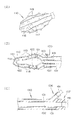
- FIG. 2A and 2B are diagrams for explaining each part of the balloon catheter according to the embodiment.
- FIG. 2A is an enlarged perspective view showing a balloon included in the balloon catheter
- FIG. 2C is a cross-sectional view taken along the line 2C-2C of FIG.
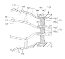
- FIG. 2 (B) It is a figure which expands and shows the dashed-dotted line 3B part shown in FIG. 2 (B).
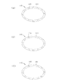
- 4A to 4C are diagrams showing examples of the shape of the through hole provided in the balloon catheter.
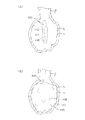
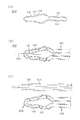
- FIG. 5 is a view for explaining a treatment method using a balloon catheter according to the embodiment, and FIG.
- FIG. 5A is a view showing a state in which a balloon included in the balloon catheter is introduced into a diseased alveoli.
- (B) is a figure which shows the state which expanded the balloon from the state of FIG. 5 (A).
- 6 is a view for explaining a treatment method using a balloon catheter according to the embodiment.
- FIG. 6A is a view showing a state in which the balloon is contracted from the state of FIG.
- FIG. 6B is a diagram illustrating a state in which the balloon is further contracted from the state of FIG.
- FIG. 7 is a view for explaining a treatment method using a balloon catheter according to the embodiment.
- FIG. 7 (A) is a drawing of the lung parenchyma attached to the balloon together with the balloon from the state of FIG. 6 (B) into the airway.
- FIG. 7B is a diagram showing a state where the balloon is cut off from the main body of the balloon catheter and the balloon is left in the airway.
- FIG. 8 is a view for explaining
- FIG. 1 shows the overall configuration of a balloon catheter according to an embodiment of the present invention.
- FIGS. 2 (A) to (C) show enlarged views for explaining each part of the balloon catheter, and FIG. The enlarged view for demonstrating the principal part of the balloon with which a balloon catheter is provided is shown.
- the balloon catheter 100 shown in FIG. 1 can be used as a medical device used for emphysema treatment, for example.
- the balloon catheter 100 reduces the effective area of the lung parenchyma L that contributes to respiration by reducing the volume of the affected lung parenchyma L (respiratory bronchiole, alveoli, alveolar passage, alveolar sac, etc.) of the emphysema patient. It is possible to increase and improve ventilation capacity.
- the application example of the balloon catheter 100 is outlined, as shown in FIGS. 5 and 6, after the first balloon 110 provided in the balloon catheter 100 is expanded in the living body, the fluidity is applied to the outer surface 111 of the first balloon 110.
- the balloon catheter 100 has a first balloon 110 and a second balloon 120 that can be expanded by fluid injection, and a first balloon 110 and a second balloon 120 attached thereto. And a hub 105 provided with a port to which various fluid tubes can be connected.
- an attachment material supply source 180 and a fluid supply source 190 can be used together with the balloon catheter 100.
- the adhering material supply source 180 is an apparatus for supplying the adhering material to the balloon catheter 100.
- a cyanoacrylate adhesive can be used as the adhesive.
- the cyanoacrylate adhesive include Medical Aron Alpha A (Daiichi Sankyo Co., Ltd.), Dermabond (J & J Co., registered trademark), and Histoacryl (B. Brown Co., registered trademark).
- a material obtained by synthesizing or mixing a hydrophobic polymer (monomer) and a hydrophilic polymer (monomer) can be used as the adhesive material.
- the hydrophobic substance include acrylamide and polyethylene.
- the hydrophilic substance include cationic polymers (monomers) such as polylysine and chitosan, anionic polymers (monomers) such as carboxymethylcellulose, and polyvinyl alcohol.
- a hydrophilic (cationic polymer) coating is previously applied to the balloon side, and an anionic polymer is applied as an adhesive, or vice versa, and an anionic polymer coating is previously applied to the balloon side. It is also possible to adopt a form in which a cationic polymer is applied and used as an adhesive.
- a biological adhesive such as isopropylacrylamide (NIPAM) can be used.
- a refrigerant such as a liquid or a gas cooled to a predetermined temperature (about ⁇ 20 to ⁇ 100 ° C.) can be used. Note that this temperature value can be changed as long as the first balloon 110 and the living tissue t adhere.
- the fluid supply source 190 is a device for supplying a fluid as a pressurized medium for expanding the second balloon 120.
- a pressurizing medium for example, physiological saline, another liquid, a gas such as air, a liquid or a solid dispersed in a gas, an aggregate of particles, or the like can be used.
- the first balloon 110 includes an internal space 113 into which a fluid for expanding the first balloon 110 flows, and a living tissue when the first balloon 110 is expanded. and an outer surface 111 at least part of which is in contact with t (see FIG. 6).
- the internal space 113 of the first balloon 110 is communicated with a first lumen 131 provided in the main body 130, and the supply of the adhering material to the first balloon 110 is performed via the first lumen 131. That is, the first balloon 110 can be expanded by the adhesive material supplied through the first lumen 131.
- the first lumen 131 is provided inside the main body 130 as a flow path through which the adhering material can flow.
- a first port 106 is provided at the proximal end of the first lumen 131 to which one end of a fluid tube 181 for supplying an adhering material is connected in a liquid-tight and air-tight manner.
- the other end of the fluid tube 181 connected to the first port 106 is connected to the adhering material supply source 180 in a liquid-tight / air-tight manner (see FIG. 1). Therefore, the adhering material supplied from the adhering material supply source 180 flows into the internal space 113 of the first balloon 110 via the fluid tube 181 and the first lumen 131 and expands the first balloon 110.
- the second balloon 120 is disposed inside the first balloon 110 so that at least a part of the second balloon 120 is covered with the first balloon 110.
- the internal space 123 of the second balloon 120 is communicated with a second lumen 132 provided in the main body 130, and the second balloon 120 can be expanded by a pressurized medium supplied through the second lumen 132. it can.
- the second balloon 120 can be deflated by discharging the pressurized medium supplied to the internal space 123 from the internal space 123 via the second lumen 132. For this reason, by operating the supply of the pressurized medium to the second balloon 120 and the discharge of the pressurized medium from the second balloon 120, the second balloon 120 is expanded and contracted separately from the first balloon 110. Can do.
- the second lumen 132 is provided inside the main body 130 as a flow path through which the pressurized medium can flow.
- a second port 107 is provided at the proximal end of the second lumen 132 to which one end of a fluid tube 191 for supplying a pressurized medium is connected in a liquid-tight and air-tight manner.
- the other end of the fluid tube 191 connected to the second port 107 is liquid-tight and air-tightly connected to the fluid supply source 190 (see FIG. 1). Therefore, the pressurized medium supplied from the fluid supply source 190 flows into the internal space 123 of the second balloon 120 via the fluid tube 191 and the second lumen 132 and expands the second balloon 120.
- the main body 130 of the balloon catheter 100 can be formed of a polymer material having excellent flexibility such as polyurethane, polyolefin, polyester, polycarbonate, polysulfone, or silicone.
- first balloon 110 and the second balloon 120 known materials used for balloons of balloon catheters in the medical field can be used.
- materials include polyethylene, polypropylene, polybutene, ethylene-propylene copolymer, ethylene-vinyl acetate copolymer, polyolefin such as ionomer, and further crosslinked or partially crosslinked products thereof, polyester such as polyethylene terephthalate, polyester elastomer, Examples thereof include polyvinyl chloride, polyurethane, polyurethane elastomer, polyphenylene sulfide, polyamide, polyamide elastomer, polymer materials such as fluororesin, silicone rubber, latex rubber and the like. Moreover, the mixture of these 2 or more may be sufficient, and the film (or sheet
- Each balloon may be provided with a radiation marker.
- the contact between the living tissue t and the outer surface 111 of the first balloon 110 can be improved by adjusting the compliance of the balloons 110 and 120.
- the term “compliance” here is described as an index for improving the ease of deformation of the balloon shape.
- the reason for improving the contact property is as follows.
- the outer surface 111 of the first balloon 110 is attached while being in contact with the living tissue t of the lung parenchyma L. When attached, the contact area between the outer surface 111 of the first balloon 110 and the living tissue t is large. If it is small, the adhesion force with which the first balloon 110 adheres to the living tissue t is reduced.
- a form for adjusting the compliance of the balloon for example, a form in which a portion having a different compliance is provided on the outer surface 111 of the first balloon 110 can be cited.
- at least a part of the outer surface 111 of the first balloon 110 is formed to have a larger compliance than other parts of the outer surface 111 of the first balloon 110 (with respect to a change in pressure for expanding the balloon, A large change in the shape of the balloon is formed).
- This makes it possible to partially flexibly deform a portion of the outer surface 111 where the compliance is large while maintaining the expandability of the entire first balloon 110 by introducing the fluid.
- the contact area between the outer surface 111 and the living tissue t can be improved to increase the contact area.
- part with a small compliance can be provided in arbitrary positions according to the convenience of other designs, such as the external dimension of the 1st balloon 110, an external shape.
- the compliance of the first balloon 110 is formed larger than the compliance of the second balloon 120. If the compliance of the first balloon 110 is increased, the outer surface 111 of the first balloon 110 can be flexibly deformed so as to follow the inner surface shape of the living tissue t when the first balloon 110 is expanded. The contact area where the outer surface 111 of the first balloon 110 contacts the living tissue t can be increased. Further, if the second balloon 120 is expanded with the outer surface 111 of the first balloon 110 attached to the living tissue t, the second balloon 120 supports the first balloon 110 from the inside so as to press the living tissue t.
- the adhesion between the outer surface 111 of the first balloon 110 and the living tissue t can be enhanced.
- the compliance of the second balloon 120 is relatively large, the support by the second balloon 120 is supported. The function becomes difficult to be demonstrated. That is, by setting the compliance of the first balloon 110 to be larger than the compliance of the second balloon 120, the support force by the second balloon 120 can be improved.
- the adjustment of the compliance for improving the contact property of the outer surface 111 of the first balloon 110 adopts the above two forms when the balloon 102 is provided with the first balloon 110 and the second balloon 120. Alternatively, only one of the forms may be adopted. As will be described later, when the second balloon 120 is not used in the balloon catheter but only the first balloon 110 is provided, a method of adjusting the compliance of the outer surface 111 of the first balloon 110 is employed. It is possible.
- the first balloon 110 is used.
- Each compliance is set so that the compliance becomes smaller in the order of the portion of the outer surface 111 of 110 having a large compliance, the portion of the outer surface 111 of the first balloon 110 having a small compliance, and the second balloon 120 in this order.
- a method for adjusting the compliance of each of the balloons 110 and 120 for example, a known method such as a method for adjusting the balloon by thinning or increasing the thickness of the balloon or a method for adjusting by adding a predetermined material to the balloon is appropriately used. It is possible to adopt.
- the first balloon 110 has a through-hole 115 that penetrates the inside of the first balloon 110 and the outer surface 111 of the first balloon 110.
- the through-hole 115 functions as a supply unit that supplies the adhering material to the outer surface 111 of the first balloon 110. That is, the adhesive material that has flowed into the internal space 113 of the first balloon 110 is caused to flow out to the outer surface 111 of the first balloon 110 through the through-hole 115, thereby improving the adhesion between the outer surface 111 and the living tissue t. Can be increased.
- the through hole 115 can be formed to have a cross-sectional shape as shown in FIGS. 4A to 4C, for example.
- the through hole 115 can be formed to have a constant diameter from the inner space 113 to the outer surface 111 of the first balloon 110.
- the through-holes 115 are formed in such a cross-sectional shape, the amount of the adhering material flowing out from each through-hole 115 can be made uniform, so that the adhering material in each part of the outer surface 111 of the first balloon 110 can be made uniform. The amount of adhesion can be made uniform.
- the through hole 115 can be formed in a tapered shape having a diameter that increases from the inner space 113 to the outer surface 111 of the first balloon 110.
- the through hole 115 When the through hole 115 is formed with such a cross-sectional shape, the adhering material is ejected from the through hole 115 and sprayed over a wide range of the living tissue t. Thereby, the area which the biological tissue t and the outer surface 111 of the 1st balloon 110 adhere increases, and the adhesiveness to the biological tissue t can be improved.
- the through hole 115 can be formed in a tapered shape having a diameter that decreases from the inner space 113 to the outer surface 121 of the first balloon 110.
- the through-hole 115 When the through-hole 115 is formed with such a cross-sectional shape, the amount of ejection of the adhering material from the through-hole 115 is reduced so that the ejection speed increases, so that the adhering material flows out to the outer surface 111 and the outer surface 111. And the biological tissue t can be efficiently attached.
- the cross-sectional shape of the through-hole 115 is not limited to the shape illustrated in FIGS. 4A to 4C, as long as the adhering material can flow out from the inner space 113 of the first balloon 110 to the outer surface 111. It is possible to change. Further, the number of through holes and the installation positions of the through holes are not limited to the numbers and installation positions shown in the drawings, and can be changed according to the use form of the balloon catheter.
- a guide portion 117 that guides the flow of the adhering material can be provided on the outer surface 111 of the first balloon 110.
- This guide part 117 can be comprised by the groove
- the guide part 117 distributes the adhering material leaking from the through-hole 115 over the entire outer surface 111 of the first balloon 110 along the guide part 117, so that the outer surface 111 of the first balloon 110 and the living tissue Adhesion with t is improved.
- the shape, installation position, outer shape, and the like of the groove that constitutes the guide portion 117 are not limited to the illustrated forms, and can be changed as long as they have a function of guiding the flow of the adhering material.
- a branch channel branched from one groove can be provided.
- the outer surface 111 of the first balloon 110 can be provided with a protruding portion 118 that protrudes toward the living tissue t to which the outer surface 111 is attached. .
- the protrusion 118 is provided to increase the contact area where the outer surface 111 of the first balloon 110 and the living tissue t come into contact with each other.
- the inner surface such as alveoli contained in the lung parenchyma L does not have a smooth surface shape, and has a slightly uneven surface shape although there are individual differences (see FIG. 5).
- the contact area between the outer surface 111 of the first balloon 110 and the living tissue t cannot be increased.
- the outer surface 111 of the first balloon 110 can be brought into close contact with the inner surface of the living tissue t.
- the contact area between the outer surface 111 of the first balloon 110 and the living tissue t can be increased.
- the balloon catheter 100 can be provided with a connection portion 160 that connects the first balloon 110 and the second balloon 120.
- the connecting portion 160 can be constituted by a columnar member that partially connects the inner surface of the first balloon 110 and the outer surface 121 of the second balloon 120. 110 and the second balloon 120 may be partially bonded or fused.
- an attachment material is supplied to the outer surface 111 of the first balloon 110, and the attachment material adheres the outer surface 111 of the first balloon 110 and the living tissue t. If the adhesive material existing in the internal space 113 of the first balloon 110 is excessively cured before the 110 is deflated, the adhesive material supplied into the first balloon 110 cannot be discharged, and the first balloon 110 is discharged. 110 cannot be contracted sufficiently. Even in such a case, if the first balloon 110 and the second balloon 120 are connected via the connecting portion 160, the first balloon 110 can be surely deflated as the second balloon 120 is deflated. it can.
- connection portion 160 it is possible to expand the first balloon 110 so as to push it toward the living tissue t as the second balloon 120 is expanded. For this reason, the contact area between the outer surface 111 of the first balloon 110 and the living tissue t can be increased by expanding the second balloon 120.
- the compliance of the second balloon 120 is smaller than the compliance of the first balloon 110, the followability of expansion / contraction of the first balloon 110 accompanying expansion / contraction of the second balloon 120 can be further enhanced. it can.
- connection unit 160 The installation position, the installation number, the outer shape, and the like of the connection unit 160 are not limited to the illustrated forms, and the first balloon 110 and the second balloon 120 are connected and the first balloon 120 is contracted as the second balloon 120 contracts. It is possible to change as long as 110 can be contracted. Moreover, when a connection part is comprised by various members, a metal material, a resin material, etc. can be used as the material of the member.
- the main body 130 of the balloon catheter 100 can be provided with a discharge unit 140 that discharges the adhering material to the outer surface 111 of the first balloon 110.
- the discharge unit 140 functions as a supply unit that supplies the adhering material to the outer surface 111 of the first balloon 110.
- the discharge unit 140 can be configured by, for example, a branch channel 143 branched from a first lumen 131 provided in the main body unit 130 and a tip opening 141 formed at the tip of the branch channel 143 as illustrated.
- the discharge unit 140 discharges the adhering material flowing through the first lumen 131 toward the outer surface 111 of the first balloon 110 via the tip opening 141.
- the discharged adhering material is applied to the outer surface 111 of the first balloon 110 to enhance the adhesion between the outer surface 111 of the first balloon 110 and the living tissue t.
- the tip opening 141 of the discharge part 140 can be disposed so as to face the groove forming the guide part 117. By arranging in this way, the discharged adhering material can be poured into the groove, and the adhering material can be efficiently distributed over the entire outer surface 111 of the first balloon 110.
- the installation position of the discharge unit 140 is not limited to the illustrated form, and can be changed as long as the adhering material can be discharged from the main body 130 of the balloon catheter 100 to the outer surface 111 of the first balloon 110. It is.
- the balloon catheter 100 has a mounting portion 171 for attaching the first balloon 110 and the main body portion 130 so as to be connectable and separable, and a second balloon 120 and the main body portion 130 for attaching so as to be separable.
- a mounting portion 172 can be provided.
- the attachment portions 171 and 172 are attached to the female screw portion 173a provided in the main body 130 and the first balloon 110 and the second balloon 120, respectively, as shown in the figure, and can be screwed into the female screw portion 173a. It can be configured by the male screw parts 173b and 173c.
- the first balloon 110 and the male screw portion 173 b provided on the first balloon 110 are connected via a predetermined connecting member 174.
- the second balloon 120 and the male screw portion 173 c provided on the second balloon 120 are connected via a predetermined connecting member 174.
- the attachment portions 171 and 172 are provided on the balloon catheter 100, the balloons 110 and 120 and the main body portion 130 can be separated by a simple operation of rotating the main body portion 130 by a hand operation.
- the male screw portion 173b provided in the first balloon 110 and the male screw portion 173c provided in the second balloon 120 are not shown so as not to prevent the flow of fluid or the like into the internal space of each balloon.
- a through hole can be provided.
- each of the attachment portions 171 and 172 is not limited to the illustrated form, and can be changed as long as the main body portion and each balloon can be connected and separated.
- a structure for separation, a structure for separation by pulling the main body 130 from a connected state, a structure for separation by applying heat to the connection portion, or the like may be used.
- FIG. 5 to FIG. 7 are diagrams showing each procedure until the balloon catheter 100 is introduced into the alveoli, which is emphysematous lung parenchyma L, and the volume of the alveoli is reduced by the balloon catheter 100.
- the practitioner specifies the lung parenchyma L that has become emphysematous and swelled in advance by a preliminary examination or the like. Then, as shown in FIG. 5A, the first balloon 110, the second balloon 120, and the main body 130 of the balloon catheter 100 are introduced into the lung parenchyma L.
- a bronchoscope generally used for emphysema treatment can be used.
- a bronchoscope is preceded by the balloon catheter 100 and introduced into the airway p (trachea, main bronchus, lobe bronchus, bronchus, bronchiole, terminal bronchiole, etc.), and the balloon is inserted into the catheter introduction channel provided in the bronchoscope.
- the catheter 100 can be inserted to guide the balloon catheter 100 to the vicinity of the lung parenchyma L.
- the first balloon 110 and the second balloon 120 can be folded into a predetermined shape, and the balloon catheter 100 can be introduced into the living body with the balloons 110 and 120 folded. is there.
- the second balloon 120 is expanded by flowing a pressurized medium into the second balloon 120.
- the first balloon 110 located outside the second balloon 120 is expanded together with the expansion of the second balloon 120.
- the adhesive material is supplied to the outer surface 111 of the first balloon 110 in a state where the outer surface 111 of the first balloon 110 is in contact with the living tissue t of the lung parenchyma L, and the outer surface 111 of the first balloon 110 and the living tissue t To attach.
- the adhering material may be supplied to the outer surface 111 of the first balloon 110 while supplying the pressurized fluid to the second balloon 120.
- the pressurized medium is discharged from the second balloon 120, and the second balloon 120 is deflated.
- the first balloon 110 contracts as the second balloon 120 contracts.
- the living tissue t attached to the outer surface 111 of the first balloon 110 is pulled in the deflation direction of the first balloon 110.
- the adhering material may be discharged from the first balloon 110 while discharging the pressurized medium from the second balloon 120.
- the first balloon 110 is continuously deflated, and the living tissue t is further deflated together with the first balloon 110.
- the volume of the lung parenchyma L can be reduced.
- the balloon catheter 100 can be drawn into the airway p, and the lung parenchyma L can be drawn into the airway p together with the balloon catheter 100.
- the volume of the pulmonary parenchyma L can be further reduced.
- the main body 130 is separated from the first balloon 110 and the second balloon 120. The balloons 110 and 120 are left in the living body, and the main body 130 is removed from the living body.
- the adhesion state of the first balloon 110 and the living tissue t is released, and the balloon catheter 100 is taken out of the living body. Also good.
- a gel or a fluid embolic material may be administered to the lung parenchyma L in order to prevent the lung parenchyma L from expanding again.
- the balloon catheter 100 according to the present embodiment can provide the following operational effects.
- an adhesive material having fluidity is supplied to the outer surface 111 of the first balloon 110, and the living body of the lung parenchyma L affected by the outer surface 111 is supplied.
- the lung parenchyma L can be reduced in accordance with the deflation of the first balloon 110.
- the volume of the diseased lung parenchyma L is reduced.
- the lung parenchyma can be physically contracted in accordance with the contraction of the first balloon 110, so that a puncturing operation performed by a bypass operation is unnecessary, and the An invasive procedure can be realized. Furthermore, since the treatment effect does not vary with each procedure, a stable treatment effect can be obtained.
- the first balloon 110 when the first balloon 110 is provided in an expandable manner by injecting an adhesive material supplied through the first lumen 131, the first balloon 110 is expanded and the outer surface 111 of the first balloon 110 and the living body. Since attachment to the tissue t can be performed simultaneously, a procedure using the balloon catheter 100 can be performed more easily and quickly.
- the balloon catheter 100 has a through-hole 115 that penetrates the inside of the first balloon 110 and the outer surface 111 of the first balloon 110, the adhering material that has flowed into the inside of the first balloon 110, Since it can be made to flow out to the outer surface 111 of the 1st balloon 110 through the through-hole 115, the adhesiveness of the outer surface 111 of the 1st balloon and the biological tissue t can be improved.
- the balloon catheter 100 has the discharge portion 140 that discharges the adhesive material to the outer surface 111 of the first balloon 110, the adhesive material can be directly applied to the outer surface 111 of the first balloon 110. Therefore, the adhesion between the outer surface 111 of the first balloon 110 and the living tissue t can be enhanced, and the therapeutic effect of the balloon catheter 100 can be improved.
- the expandability of the entire first balloon 110 by introduction of a fluid is possible. It is possible to partially flexibly deform a portion of the outer surface 111 where compliance is largely formed while maintaining the above. Thereby, since the contact property between the outer surface 111 of the first balloon 110 and the living tissue t can be improved and the contact area can be increased, the therapeutic effect of the balloon catheter 100 can be improved.
- the second balloon 120 can be expanded and contracted by operating the second balloon 120.
- the contact of the one balloon 110 with the living tissue and the pulling of the living tissue p in the contraction direction of the first balloon 110 can be performed smoothly.
- the balloon catheter 100 has the connection portion 160 that connects the first balloon 110 and the second balloon 120, the followability of the expansion / contraction of the first balloon 110 accompanying the expansion / contraction of the second balloon 120 is improved. Therefore, the therapeutic effect of the balloon catheter 100 can be improved.
- the first balloon 110 conforms to the inner surface shape of the living tissue t when the first balloon 110 is expanded. Since the outer surface 111 of 110 can be flexibly deformed, the contact area of the outer surface 111 of the first balloon 110 with the living tissue t can be increased, and the therapeutic effect of the balloon catheter 100 can be improved. it can.
- the guide part 117 for guiding the flow of the adhering material is provided on the outer surface 111 of the first balloon 110, the adhering material is spread over the entire outer surface 111 of the first balloon 110 by the guide part 117. Therefore, the adhesion between the outer surface 111 of the first balloon 110 and the living tissue t can be improved.
- the outer surface 111 of the first balloon 110 when the outer surface 111 of the first balloon 110 is provided with the protruding portion 118 that protrudes toward the living tissue t, the outer surface 111 of the first balloon 110 can be brought into close contact with the living tissue t.
- the contact area between the outer surface 111 of the first balloon 110 and the living tissue t can be increased, and the therapeutic effect of the balloon catheter 100 can be improved.
- the first balloon 110 and the second balloon 120 are placed in the lung parenchyma L. Therefore, the degree of freedom of the procedure using the balloon catheter 100 can be increased.
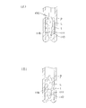
- FIG. 8 is a diagram illustrating a modification of the above-described embodiment.
- Modification 1 shown in FIG. 8A is a modification regarding the balloon structure of the balloon catheter.
- Modification 2 shown in FIG. 8B and Modification 3 shown in FIG. It is a modification regarding the guide means which guides a balloon catheter to substantial.
- the same members as those described in the above-described embodiment are denoted by the same reference numerals, and description thereof is omitted.
- the balloon catheter 100 includes the two balloons of the first balloon 110 and the second balloon 120.
- the balloon catheter 200 includes only one balloon 110.
- the volume of the lung parenchyma L is reduced by supplying an attachment material to the outer surface 111 of the balloon 110 included in the balloon catheter 200 and contracting the balloon 110 with the outer surface 111 and the living tissue t adhered to each other. Can do.
- the adhering material may be supplied to the outer surface 111 through a through hole 115 penetrating the inside of the first balloon 110 and the outer surface 111, or the discharge unit 140 functioning as a supply unit may be provided. It is also possible to install and supply the adhering material by the discharge unit 140.
- the structure similar to embodiment described previously is employable.
- the method of performing the operation of introducing the balloon catheter 100 to the lung parenchyma L using a bronchoscope is exemplified.
- a guide wire 310 generally used in the medical field is used.
- the balloon catheter 300 can be introduced into the living body.
- the introduction of the balloon catheter 300 can be performed using a guide wire 310 integrally attached to the balloon catheter 300.
- a configuration in which the balloon catheter 300 is introduced using a guiding catheter 320 into which the balloon catheter 300 can be inserted together with the guide wire 310 can be adopted.
- a guide wire insertion lumen is separately provided in the main body 130.
- the introduction of the balloon catheter 300 can be performed by the following procedure.
- the guide wire 310 is introduced to a predetermined treatment site by an endoscope or a bronchoscope, and after the guiding catheter 320 is inserted along the guide wire 310, the guide wire 310 is removed, and the guiding catheter 320 is inserted into the guiding catheter 320.
- the balloon catheter 300 is inserted and the balloon 110 is placed at the target treatment site.
- the method of introducing the balloon catheter into the lung parenchyma serving as a treatment site can be changed as long as the balloon can be guided to a predetermined site.
- the balloon catheter according to the present invention has been described based on the embodiments and the modified examples.
- the balloon catheter of the present invention can be modified within the scope described in the claims, and The configuration, material, structure, and the like are not limited to those described in the above-described embodiments and modifications.
Landscapes
- Health & Medical Sciences (AREA)
- Life Sciences & Earth Sciences (AREA)
- Surgery (AREA)
- Heart & Thoracic Surgery (AREA)
- Engineering & Computer Science (AREA)
- Animal Behavior & Ethology (AREA)
- Veterinary Medicine (AREA)
- Public Health (AREA)
- Biomedical Technology (AREA)
- General Health & Medical Sciences (AREA)
- Molecular Biology (AREA)
- Nuclear Medicine, Radiotherapy & Molecular Imaging (AREA)
- Medical Informatics (AREA)
- Vascular Medicine (AREA)
- Reproductive Health (AREA)
- Pulmonology (AREA)
- Child & Adolescent Psychology (AREA)
- Hematology (AREA)
- Biophysics (AREA)
- Anesthesiology (AREA)
- Otolaryngology (AREA)
- Oral & Maxillofacial Surgery (AREA)
- Dentistry (AREA)
- Media Introduction/Drainage Providing Device (AREA)
- Surgical Instruments (AREA)
Description
本発明は、肺気腫治療に用いられるバルーンカテーテルに関する。
慢性閉塞性肺疾患の1つとして、肺気腫が知られている。肺気腫は、酸素と二酸化炭素の交換を行う肺胞の隔壁が壊れて肺胞同士がつながり、壊れた肺胞が大きく膨らんで弾力性や収縮性のない状態(線維化状態)となり、肺胞の有効面積が減って換気能力が低下する疾患である。
通常の肺胞は、呼気において肺の収縮に伴って収縮するが、肺気腫になると呼気において収縮せず、肺が縮む際に、気管支が周囲の収縮できない肺胞によって押しつぶされ、空気が出にくくなる症状があらわれる。このような肺気腫の治療法として、例えば、特許文献1に示されるような気道バイパスを利用した治療法が提案されている。気道バイパスを用いた治療では、気道壁に開口部を形成し、隣接している拡大した肺胞へのバイパスを形成することで、狭窄された気管支に呼気を通さず、直接気道へ呼気を抜けさせることを可能にする。このようなバイパスを形成する際には、まず穿刺ツールを気道の開口を形成する部位まで到達させて穿刺し、穿刺して形成された気道壁の孔をバルーンにより広げ、最後に、開口が治癒して閉じないように開口状態を維持するための部材を開口部に留置する。しかしながら、このような治療においては、気道壁を穿刺して開口部を形成するため、手技には出血が伴い、生体への負担が大きい。
これに対して、特許文献2、特許文献3には、上記のような外科的な手技を行わず、気腫化した肺胞の体積を減少させて換気能力を回復させる方法が提案されている。
特許文献2に記載の方法では、気管支を塞ぐ閉塞具を使用し、空気の供給を遮断することにより病変した肺胞の体積を減少させている。一方、特許文献3に記載の方法では、線維化の進行を促すゲルを投与し、病変した肺胞を構成する生体組織を崩壊させて肺胞の体積を減少させている。これらの治療方法によれば、気道バイパスを用いる治療方法に比べて低侵襲な治療を実現し得る。
しかしながら、閉塞具を利用する場合には、気管支に留置させた閉塞具が脱落したり、留置位置から位置ずれしたりすることがあるため、確実な治療効果を期待することができない。また、線維化を促すゲルを利用する場合には、患者ごとに治療効果のばらつきが生じるため、患者によっては十分な治療効果を得ることができないことがある。
本発明は、上述した課題を解決するためになされたものであり、低侵襲かつ効果的な肺気腫治療を可能にするバルーンカテーテルを提供することを目的とする。
上記目的を達成するための本発明のバルーンカテーテルは、以下のような構成を有する。
(1)拡張および収縮可能に設けられ、生体内において拡張した際に外表面の少なくとも一部を生体組織に接触させるバルーンと、前記バルーンを拡張させるための流体が流通可能なルーメンを備える本体部と、前記バルーンの外表面を前記生体組織に付着させる流動性を備えた付着材を前記バルーンの外表面へ供給する供給部と、を有するバルーンカテーテル。
(2)前記バルーンは、前記ルーメンを介して供給される前記付着材の注入によって拡張可能に設けられている、上記(1)に記載のバルーンカテーテル。
(3)前記供給部は、前記生体組織に付着される前記バルーンの内部から当該バルーンの外表面に貫通する貫通孔を有する、上記(2)に記載のバルーンカテーテル。
(4)前記供給部は、前記本体部に設けられ前記生体組織に付着される前記バルーンの外表面へ前記付着材を吐出させる吐出部を有する上記(2)または上記(3)に記載のバルーンカテーテル。
(5)前記バルーンの外表面の少なくとも一部は、当該外表面における他の部位よりもコンプライアンスが大きく形成されている、上記(1)~(4)のいずれか1つに記載のバルーンカテーテル。
(6)前記バルーンは、前記生体組織に接触される前記外表面を備え、前記付着材の注入によって拡張される第1バルーンと、前記第1バルーンに少なくとも一部が覆われるように配置され、前記第1バルーンとは個別に拡張および収縮可能な第2バルーンと、を有し、前記本体部は、前記第1バルーンとの間で前記付着材を流通させる第1ルーメンと、前記第2バルーンとの間で当該第2バルーンを拡張させるための流体を流通させる第2ルーメンと、を有する上記(1)~(5)のいずれか1つに記載のバルーンカテーテル。
(7)前記第1バルーンと前記第2バルーンを接続する接続部をさらに有する、上記(6)に記載のバルーンカテーテル。
(8)前記第1バルーンのコンプライアンスが、前記第2バルーンのコンプライアンスよりも大きく形成されている、上記(6)または上記(7)に記載のバルーンカテーテル。
(9)前記生体組織に付着される前記バルーンの外表面には、前記付着材の流れをガイドするガイド部が設けられている、上記(1)~(8)のいずれか1つに記載のバルーンカテーテル。
(10)前記生体組織に付着される前記バルーンの外表面には、前記生体組織へ向けて突出する突出部が設けられている、上記(1)~(9)のいずれか1つに記載のバルーンカテーテル。
(11)前記生体組織に付着される前記バルーンと前記本体部とを接続分離可能に取り付ける取り付け部をさらに有する上記(1)~(10)のいずれか1つに記載のバルーンカテーテル。
上記(1)に記載の発明によれば、バルーンカテーテルが備えるバルーンを生体内において拡張させた後、バルーンの外表面に流動性を備える付着材を供給してバルーンの外表面と病変した肺実質の生体組織を付着させ、さらに、このバルーンを収縮させることにより、バルーンの収縮に伴わせて肺実質を縮小させることができ、その結果、病変した肺実質の体積を減少させることができる。そして、当該バルーンカテーテルを使用した手技によれば、バルーンの収縮に伴わせて肺実質を物理的に収縮させることができるため、バイパス術で行われる穿刺作業が不要であり、低侵襲な手技を実現することができる。さらに、手技の度に治療効果にばらつきが生じることもないため、安定した治療効果を得ることができる。
また、上記(2)に記載の発明のように、本体部に設けられたルーメンを介して供給される付着材の注入によってバルーンが拡張可能に設けられている場合には、バルーンの拡張、およびバルーンの外表面と生体組織との付着を同時に行うことができるため、バルーンカテーテルを用いた手技をより簡単かつ迅速に行うことができる。
また、上記(3)に記載の発明のように、バルーンカテーテルが、当該バルーンの内部と当該バルーンの外表面とを貫通する貫通孔を有する場合には、バルーンの内部に流入した付着材を、貫通孔を介してバルーンの外表面に流出させることができるため、バルーンの外表面と生体組織との付着性を高めることができる。
また、上記(4)に記載の発明のように、バルーンカテーテルが、バルーンの外表面へ付着材を吐出させる吐出部を有する場合には、バルーンの外表面に直接的に付着材を塗布することができるため、バルーンの外表面と生体組織との付着性を高めることができ、バルーンカテーテルによる治療効果を向上させることができる。
また、上記(5)に記載の発明のように、バルーンの外表面の少なくとも一部が、当該外表面における他の部位よりもコンプライアンスが大きく形成されている場合には、流動体の導入によるバルーン全体の拡張性を保ちつつ、当該外表面においてコンプライアンスが大きく形成された部位を部分的に柔軟に変形させことが可能になる。これにより、バルーンの外表面と生体組織との接触性を向上させて接触面積の増加を図ることができるため、バルーンカカテーテルによる治療効果を向上させることができる。
また、上記(6)に記載の発明のように、バルーンカテーテルが、第1バルーンを有するとともに、第1バルーンの内側に配置された第2バルーンを有する場合には、第2バルーンの拡張および収縮を操作することにより、第1バルーンの生体組織への接触、および第1バルーンの収縮方向への生体組織の牽引を円滑に行うことができる。
また、上記(7)に記載の発明のように、バルーンカテーテルが、第1バルーンと第2バルーンを接続する接続部を有する場合には、第2バルーンの拡張・収縮に伴う第1バルーンの拡張・収縮の追従性を高めることができるため、バルーンカテーテルによる治療効果を向上させることができる。
また、上記(8)に記載の発明のように、第2バルーンのコンプライアンスが、第1バルーンのコンプライアンスよりも大きく形成されている場合には、第1バルーンを拡張させた際に生体組織の内面形状に沿うように第1バルーンの外表面を柔軟に変形させることができるため、第1バルーンの外表面が生体組織に接触する接触面積を増加させることができ、バルーンカテーテルによる治療効果を向上させることができる。
また、上記(9)に記載の発明のように、生体組織に接触させられるバルーンの外表面に付着材の流れをガイドするガイド部が設けられている場合には、ガイド部によってバルーンの外表面全体に付着材を行き渡らせることができるため、バルーンの外表面と生体組織の付着性を向上させることができる。
また、上記(10)に記載の発明のように、生体組織に接触させられるバルーンの外表面に生体組織へ向けて突出する突出部が設けられている場合には、第1バルーンの外表面を生体組織に密着させることができるため、第1バルーンの外表面と生体組織との接触面積を増加させることができ、バルーンカテーテルによる治療効果を向上させることができる。
また、上記(11)に記載の発明のように、本体部に対してバルーンを接続分離可能に取り付ける取り付け部を有する場合には、バルーンを肺実質に留置する手技を行うことが可能になるため、バルーンカテーテルによる手技の自由度を高めることができる。
以下、図面を参照して、本発明の実施の形態を説明する。なお、図面の寸法比率は、説明の都合上、誇張されており、実際の比率とは異なる場合がある。
図1には、本発明の実施形態に係るバルーンカテーテルの全体構成を示し、図2(A)~(C)には、バルーンカテーテルの各部を説明するための拡大図を示し、図3には、バルーンカテーテルが備えるバルーンの要部を説明するための拡大図を示す。
図1に示すバルーンカテーテル100は、例えば、肺気腫治療に用いられる医療デバイスとして使用することができる。バルーンカテーテル100は、肺気腫患者の病変した肺実質L(呼吸細気管支、肺胞、肺胞道、及び肺胞嚢等)の体積を減少させることにより、呼吸に寄与する肺実質Lの有効面積を増加させて換気能力を向上させることを可能にする。バルーンカテーテル100の適用例を概説すれば、図5、図6に示すように、バルーンカテーテル100が備える第1バルーン110を生体内において拡張させた後、第1バルーン110の外表面111に流動性を備える付着材を供給し、この外表面111と病変した肺実質Lの生体組織tとを付着させ、さらに、第1バルーン110を収縮させて、第1バルーン110の収縮に伴わせて肺実質Lを縮小させる。このような手技により、病変した肺実質Lの体積を減少させることができる。以下、本実施形態について詳述する。
図1、図2(B)、図3に示すように、バルーンカテーテル100は、流体の注入によって拡張可能な第1バルーン110および第2バルーン120と、第1バルーン110および第2バルーン120が取り付けられた長尺状の本体部130と、各種の流体チューブが接続可能なポートが設けられたハブ105とを有している。
図1に示すように、バルーンカテーテル100を使用した治療を行う際には、バルーンカテーテル100とともに、付着材供給源180および流体供給源190を用いることができる。
付着材供給源180は、バルーンカテーテル100に付着材を供給するための装置である。この付着材には、例えば、シアノアクリレート系接着剤を用いることができる。シアノアクリレート系接着剤としては、例えば、医療用アロンアルファA(第一三共社製)、ダーマボンド(J&J社製、登録商標)、ヒストアクリル(B.Brown社製、登録商標)などが挙げられる。
また、付着材には、例えば、疎水性ポリマー(モノマー)と親水性ポリマー(モノマー)を合成または混合したものを用いることもできる。疎水性物質としては、例えば、アクリルアミド、ポリエチレンが挙げられる。親水性物質としては、例えば、ポリリジン、キトサンなどのカチオン系ポリマー(モノマー)、カルボキシメチルセルロースなどのアニオン系ポリマー(モノマー)、ポリビニルアルコールが挙げられる。
また、例えば、親水性(カチオン系ポリマー)コーティングをバルーン側に予め施しておき、アニオン系ポリマーを塗布して接着剤として使用する形態、あるいはその逆で、アニオン系ポリマーコーティングをバルーン側に予め施しておき、カチオン系ポリマーを塗布して接着剤として使用する形態を採用することもできる。その他にも、イソプロピルアクリルアミド(NIPAM)などの生体用の接着剤を用いることができる。
また、付着材には、例えば、所定の温度(-20~-100℃程度)に冷却された液体やガスなどの冷媒を用いることもできる。なお、この温度の値は第1バルーン110と生体組織tが接着する限りにおいて変更可能である。
流体供給源190は、第2バルーン120を拡張するための加圧媒体としての流体を供給するための装置である。加圧媒体には、例えば、生理食塩水、他の液体、空気等の気体、液体中や気体中に固体が分散したもの、または粒子の集合体等を用いることができる。
図2(B)、図3に示すように、第1バルーン110は、第1バルーン110を拡張するための流体が流入される内部空間113と、当該第1バルーン110が拡張した際に生体組織tにその一部が少なくとも接触させられる外表面111とを有する(図6を参照)。第1バルーン110の内部空間113は、本体部130が備える第1ルーメン131に連通されており、第1バルーン110への付着材の供給はこの第1ルーメン131を介して行われる。すなわち、第1バルーン110は、第1ルーメン131を通じて供給される付着材によって拡張させることができる。
図2(C)に示すように、第1ルーメン131は、付着材が流通可能な流路として本体部130の内部に設けられる。第1ルーメン131の基端には、付着材供給用の流体チューブ181の一端が液密・気密に接続される第1ポート106が設けられる。第1ポート106に接続された流体チューブ181の他端は、付着材供給源180に液密・気密に接続される(図1を参照)。したがって、付着材供給源180から供給された付着材は、流体チューブ181および第1ルーメン131を経由して第1バルーン110の内部空間113へ流入し、第1バルーン110を拡張させる。
図2(B)、図3に示すように、第2バルーン120は、その少なくとも一部が第1バルーン110に覆われるように、第1バルーン110の内側に配置される。第2バルーン120の内部空間123は、本体部130が備える第2ルーメン132に連通されており、第2バルーン120は、この第2ルーメン132を介して供給される加圧媒体によって拡張させることができる。また、内部空間123に供給した加圧媒体を、第2ルーメン132を介して内部空間123から排出させることにより、第2バルーン120を収縮させることもできる。このため、第2バルーン120への加圧媒体の供給および第2バルーン120からの加圧媒体の排出を操作することにより、第2バルーン120を第1バルーン110とは個別に拡張および収縮させることができる。
図2(C)に示すように、第2ルーメン132は、加圧媒体が流通可能な流路として本体部130の内部に設けられる。第2ルーメン132の基端には、加圧媒体供給用の流体チューブ191の一端が液密・気密に接続される第2ポート107が設けられる。第2ポート107に接続された流体チューブ191の他端は、流体供給源190に液密・気密に接続される(図1を参照)。したがって、流体供給源190から供給された加圧媒体は、流体チューブ191および第2ルーメン132を経由して第2バルーン120の内部空間123へ流入し、第2バルーン120を拡張させる。
バルーンカテーテル100の本体部130は、例えば、ポリウレタン、ポリオレフィン、ポリエステル、ポリカーボネイト、ポリサルフォンやシリコーンのような柔軟性に優れた高分子材料等で形成することができる。
第1バルーン110および第2バルーン120の材料には、医療分野におけるバルーンカテーテルのバルーンに用いられる公知の材料を用いることができる。材料としては、例えば、ポリエチレン、ポリプロピレン、ポリブテン、エチレンープロピレン共重合体、エチレンー酢酸ビニル共重合体、アイオノマーなどのポリオレフィン、さらにはこれらの架橋もしくは部分架橋物、ポリエチレンテレフタレートなどのポリエステル、ポリエステルエラストマー、ポリ塩化ビニル、ポリウレタン、ポリウレタンエラストマー、ポリフェニレンサルファイド、ポリアミド、ポリアミドエラストマー、フッ素樹脂等の高分子材料、シリコーンゴム、ラテックスゴム等が挙げられる。また、これらの2以上の混合物であってもよく、これらを適宜積層したフィルム(またはシート)も挙げられる。また、各バルーンには、放射線マーカーなどを設けてもよい。
バルーンカテーテル100においては各バルーン110、120のコンプライアンスを調整することにより、生体組織tと第1バルーン110の外表面111との接触性の向上を図ることができる。なお、ここでいうコンプライアンスとは、バルーン形状の変形し易さを図る指標として説明する。接触性を向上させるのは、次のような理由による。第1バルーン110の外表面111は、肺実質Lの生体組織tに接触させた状態で付着させられるが、付着させる際に、第1バルーン110の外表面111と生体組織tとの接触面積が小さいと、第1バルーン110が生体組織tに付着する付着力が低下してしまう。このような場合には、バルーンの収縮に伴わせて生体組織tを収縮方向へ牽引して肺実質Lの体積を減少させることが難しくなってしまう。このため、生体組織tと第1バルーン110の外表面111との接触性の向上が図られることが好ましくなる。
バルーンのコンプライアンスを調整する形態としては、例えば、第1バルーン110の外表面111にコンプライアンスが異なる部位を設ける形態が挙げられる。具体的には、第1バルーン110の外表面111の少なくとも一部が、第1バルーン110の外表面111における他の部位よりもコンプライアンスが大きく形成される(バルーンを拡張する圧力の変化に対し、バルーンの形状の変化が大きく形成される)。これにより、流動体の導入による第1バルーン110全体の拡張性を保ちつつ、外表面111においてコンプライアンスが大きく形成された部位を部分的に柔軟に変形させることが可能になるため、第1バルーン110の外表面111と生体組織tとの接触性を向上させて接触面積の増加を図ることができる。なお、第1バルーン110におけるコンプライアンスが大きい部位、およびコンプライアンスが小さい部位は、第1バルーン110の外形寸法や外形形状等、その他の設計の都合に応じて任意の位置に設けることができる。
また、コンプライアンスを調整する形態としては、例えば、第1バルーン110のコンプライアンスと第2バルーン120のコンプライアンスを異ならせる形態が挙げられる。具体的には、第1バルーン110のコンプライアンスが、第2バルーン120のコンプライアンスよりも大きく形成される。第1バルーン110のコンプライアンスを大きくすれば、第1バルーン110を拡張させた際に生体組織tの内面形状に沿うように第1バルーン110の外表面111を柔軟に変形させることが可能になるため、第1バルーン110の外表面111が生体組織tに接触する接触面積を増加させることができる。また、第1バルーン110の外表面111を生体組織tに付着させた状態で第2バルーン120を拡張すれば、第2バルーン120が第1バルーン110を生体組織tに押し付けるように内側から支持するため、第1バルーン110の外表面111と生体組織tとの付着性を高めることができるが、第2バルーン120のコンプライアンスが比較的大きく形成されていると、このような第2バルーン120による支持機能が発揮され難くなる。つまり、第1バルーン110のコンプライアンスを第2バルーン120のコンプライアンスよりも大きく設定することにより、第2バルーン120による支持力を向上させることもできる。
第1バルーン110の外表面111の接触性の向上を図るためのコンプライアンスの調整は、バルーンカテーテル100に第1バルーン110および第2バルーン120が設けられる場合には、上記2つの形態を採用してもよいし、いずれか一方の形態のみを採用してもよい。また、後述するように、バルーンカテーテルに第2バルーン120が用いられず、第1バルーン110のみが設けられる形態にあっては、第1バルーン110の外表面111のコンプライアンスを調整する方法を採用することが可能である。
また、第1バルーン110の外表面111にコンプライアンスが大きな部位および小さな部位を設け、さらに第1バルーン110のコンプライアンスと第2バルーン120のコンプライアンスを異ならせた形態を採用する場合には、第1バルーン110の外表面111のコンプライアンスが大きい部位、第1バルーン110の外表面111のコンプライアンスが小さい部位、第2バルーン120の順にコンプライアンスが小さくなるように各コンプライアンスが設定される。
また、各バルーン110、120のコンプライアンスの調整方法には、例えば、バルーンの肉厚を薄くまたは厚くして調整する方法や、バルーンに所定の材料を添加して調整する方法など公知の方法を適宜採用することが可能である。
図2(A)、図2(B)、図3に示すように、第1バルーン110には、当該第1バルーン110の内部と当該第1バルーン110の外表面111とを貫通する貫通孔115を設けることができる。この貫通孔115は第1バルーン110の外表面111へ付着材を供給する供給部として機能する。すなわち、第1バルーン110の内部空間113に流入させた付着材を、貫通孔115を介して第1バルーン110の外表面111に流出させることにより、外表面111と生体組織tとの付着性を高めることができる。貫通孔115は、例えば、図4(A)~(C)に示すような断面形状を有するように形成することができる。
図4(A)に示すように、貫通孔115は、第1バルーン110の内部空間113から外表面111にかけて一定の径を有するように形成することができる。このような断面形状で貫通孔115が形成される場合、各貫通孔115から流出する付着材の流出量を均一にすることができるため、第1バルーン110の外表面111の各部における付着材の付着量を均一にすることができる。また、図4(B)に示すように、貫通孔115は、第1バルーン110の内部空間113から外表面111にかけて径が大きくなるテーパー状に形成することができる。このような断面形状で貫通孔115が形成される場合、付着材は貫通孔115から噴出されて生体組織tの広範な範囲に吹き付けられる。これにより、生体組織tと第1バルーン110の外表面111とが付着する面積が増加し、生体組織tへの付着性を高めることができる。また、図4(C)に示すように、貫通孔115は、第1バルーン110の内部空間113から外表面121にかけて径が小さくなるテーパー状に形成することができる。このような断面形状で貫通孔115を形成する場合、貫通孔115からの付着材の噴出量が絞られることにより、噴出速度が増加するため、外表面111への付着材の流出および外表面111と生体組織tとの付着を効率的に行うことができる。
貫通孔115の断面形状は、図4(A)~(C)に例示した形状に限定されず、第1バルーン110の内部空間113から外表面111へ付着材を流出させることが可能な限りにおいて変更することが可能である。また、貫通孔の個数や貫通孔の設置位置も、各図において示される個数や設置位置に限定されるものではなく、バルーンカテーテルの使用形態に応じて変更することが可能である。
図2(A)、図3に示すように、第1バルーン110の外表面111には、付着材の流れをガイドするガイド部117を設けることができる。このガイド部117は、例えば、第1バルーン110に設けられた貫通孔115に連通する溝によって構成することができる。ガイド部117は、貫通孔115から漏れ出た付着材を、当該ガイド部117に沿って第1バルーン110の外表面111の全体に行き渡らせることにより、第1バルーン110の外表面111と生体組織tとの付着性を向上させる。
ガイド部117を構成する溝の形状や設置位置、外形形状等は、図示される形態に限定されず、付着材の流れをガイドする機能を有する限りにおいて変更することが可能である。例えば、溝の幅、深さを所定の寸法以下に形成することによって毛細管現象を利用した付着材の流れを形成する流路を構成することができる。また、例えば、一つの溝から分岐する分流路を設けることもできる。このような構成を採用することにより、第1バルーン110の外表面111全体へ効率的に付着材を行き渡らせることができる。
図2(A)、図2(B)に示すように、第1バルーン110の外表面111には、この外表面111を付着させる生体組織tに向けて突出する突出部118を設けることができる。突出部118は、第1バルーン110の外表面111と生体組織tとが接触する接触面積を増加するために設けられる。肺実質Lに含まれる肺胞などの内面は、平滑な面形状を備えておらず、個体差はあるものの多少凹凸した面形状を備える(図5を参照)。このような内面形状に対して第1バルーン110の外表面111が平滑に形成されていると、第1バルーン110の外表面111と生体組織tとの接触面積を増加させることができない。これに対して、第1バルーン110の外表面111に図示するような突出部118が設けられる場合には、第1バルーン110の外表面111を生体組織tの内面に密着させることができるため、第1バルーン110の外表面111と生体組織tとの接触面積を増加させることができる。
図2(B)、図3に示すように、バルーンカテーテル100には、第1バルーン110と第2バルーン120とを接続する接続部160を設けることができる。接続部160は、図示するように、第1バルーン110の内表面と第2バルーン120の外表面121とを部分的に接続する柱形状の部材によって構成することができるが、例えば、第1バルーン110と第2バルーン120とを部分的に接着や融着することで構成してもよい。
バルーンカテーテル100を使用した手技においては、第1バルーン110の外表面111に付着材を供給し、この付着材によって第1バルーン110の外表面111と生体組織tとを付着させるが、第1バルーン110を収縮させる前に、第1バルーン110の内部空間113内に存在する付着材の硬化が過度に進行すると、第1バルーン110内に供給した付着材を排出させることができず、第1バルーン110を十分に収縮させることができない。このような場合においても、第1バルーン110と第2バルーン120とが接続部160を介して接続されていれば第2バルーン120の収縮に伴わせて第1バルーン110を確実に収縮させることができる。さらに、接続部160が設けられる場合には、第2バルーン120の拡張に伴わせて第1バルーン110を生体組織tに向けて押し広げるように拡張させることが可能になる。このため、第2バルーン120を拡張させることにより、第1バルーン110の外表面111と生体組織tの接触面積を増加させることができる。特に、第2バルーン120のコンプライアンスが第1バルーン110のコンプライアンスに比べて小さな場合には、第2バルーン120の拡張・収縮に伴う第1バルーン110の拡張・収縮の追従性をより一層高めることができる。
接続部160の設置位置、設置個数、外形形状等は、図示される形態に限定されず、第1バルーン110と第2バルーン120を接続して第2バルーン120の収縮に伴わせて第1バルーン110を収縮させることが可能な限りにおいて変更することが可能である。また、各種の部材によって接続部を構成する場合には、その部材の材料として金属材料、樹脂材料などを用いることができる。
図3に示すように、バルーンカテーテル100の本体部130には、第1バルーン110の外表面111へ付着材を吐出させる吐出部140を設けることができる。この吐出部140は第1バルーン110の外表面111へ付着材を供給する供給部として機能する。
吐出部140は、例えば、図示するように本体部130に設けられた第1ルーメン131から分岐する分流路143および分流路143の先端に形成された先端開口141によって構成することができる。吐出部140は、第1ルーメン131を流れる付着材を先端開口141を介して第1バルーン110の外表面111へ向けて吐出させる。吐出された付着材は、第1バルーン110の外表面111に塗布され、第1バルーン110の外表面111と生体組織tとの付着性を高める。なお、図示するように、吐出部140の先端開口141をガイド部117をなす溝に臨むように配置することができる。このように配置することにより、吐出された付着材を溝内へ流し込むことができ、第1バルーン110の外表面111全体に付着材を効率的に行き渡らせることができる。
吐出部140の設置位置等は、図示される形態に限定されず、バルーンカテーテル100の本体部130から第1バルーン110の外表面111へ付着材を吐出させることが可能な限りにおいて変更すること可能である。
図3に示すように、バルーンカテーテル100には、第1バルーン110と本体部130を接続分離可能に取り付けるための取り付け部171、および第2バルーン120と本体部130を接続分離可能に取り付けるための取り付け部172を設けることができる。
各取り付け部171、172は、例えば、図示するように本体部130に設けられた雌ネジ部173a、および第1バルーン110、第2バルーン120のそれぞれに取り付けられ雌ネジ部173aに対してねじ込み可能な雄ネジ部173b、173cによって構成することができる。第1バルーン110と当該第1バルーン110に設けられた雄ネジ部173bは所定の連結部材174を介して連結される。また、第2バルーン120と当該第2バルーン120に設けられた雄ネジ部173cは所定の連結部材174を介して連結される。バルーンカテーテル100に取り付け部171、172が設けられる場合には、本体部130を手元の操作によって回転させる簡単な作業によって各バルーン110、120と本体部130との切り離しを行うことができる。なお、第1バルーン110に設けられた雄ネジ部173b、および第2バルーン120に設けられた雄ネジ部173cには、各バルーンの内部空間への流体等の流入を妨げないように、図示しない貫通孔を設けることができる。
各取り付け部171、172の構成は、図示される形態に限定されず、本体部と各バルーンを接続および分離させることが可能な限りにおいて変更することが可能であり、例えば、嵌合式で接続および分離する構造、接続された状態から本体部130を引っ張ることによって分離させる構造、接続部分に熱を付与することによって分離させる構造などを用いてもよい。
次に、図5~図7を参照して、本実施形態に係るバルーンカテーテル100を使用した手技を説明する。図5~図7は、気腫化した肺実質Lである肺胞へバルーンカテーテル100を導入し、バルーンカテーテル100によって肺胞の体積を減少させるまでの各手順を示す図である。
手技に際して、施術者は、気腫化して膨らんだ肺実質Lを予備検査等によって予め特定する。そして、図5(A)に示すように、バルーンカテーテル100の第1バルーン110、第2バルーン120、および本体部130を肺実質Lへ導入する。
バルーンカテーテル100の導入には、例えば、肺気腫治療に一般的に用いられる気管支鏡を利用することができる。気管支鏡をバルーンカテーテル100に先行させて気道p(気管、主気管支、葉気管支、気管支、細気管支、及び終末細気管支等)内へ導入し、気管支鏡に設けられたカテーテル導入用のチャンネルにバルーンカテーテル100を挿通させて、バルーンカテーテル100を肺実質L近傍まで案内することができる。なお、バルーンカテーテル100を導入する前に、第1バルーン110および第2バルーン120を所定の形状に折り畳み、各バルーン110、120を折り畳んだ状態でバルーンカテーテル100を生体内へ導入することも可能である。
次に、第2バルーン120へ加圧媒体を流入させて第2バルーン120を拡張させる。この際、図5(B)に示すように、第2バルーン120の拡張とともに第2バルーン120の外側に位置する第1バルーン110も拡張する。そして、第1バルーン110の外表面111が肺実質Lの生体組織tに接触した状態で第1バルーン110の外表面111へ付着材を供給し、第1バルーン110の外表面111と生体組織tを付着させる。なお、この手順において、第2バルーン120へ加圧流体を供給しつつ、第1バルーン110の外表面111へ付着材を供給してもよい。
次に、第2バルーン120から加圧媒体を排出させ、第2バルーン120を収縮させる。この際、図6(A)に示すように、第1バルーン110は第2バルーン120の収縮に伴って収縮する。第1バルーン110が収縮すると、第1バルーン110の外表面111に付着した生体組織tが第1バルーン110の収縮方向へ引っ張られる。なお、この手順において、第2バルーン120から加圧媒体を排出させつつ、第1バルーン110から付着材を排出させてもよい。
図6(B)に示すように、第1バルーン110を引き続き収縮させて、第1バルーン110とともに生体組織tをさらに収縮させる。ここまでの手順により、病変した肺実質Lの体積を減少させることができる。
その後、例えば、図7(A)に示すように、バルーンカテーテル100を気道p内に引き込み、バルーンカテーテル100とともに肺実質Lを気道p内に引き込むこともできる。このような、手順を行うことにより、病変した肺実質Lの体積をより一層減少させることができる。そして、図7(B)に示すように、第1バルーン110および第2バルーン120から本体部130を切り離す。各バルーン110、120は生体内に留置させ、本体部130は生体から取り除く。
なお、図7(A)に示すような気道pへの肺実質Lの引き込みを行うことなく、第1バルーン110と生体組織tの付着状態を解除させて、バルーンカテーテル100を生体外へ取り出してもよい。また、肺実質Lを収縮させた後に、この肺実質Lが再度膨張することを防止するために、肺実質Lへゲルや流動状の塞栓材を投与してもよい。
本実施形態に係るバルーンカテーテル100は、以下のような作用効果を奏することができる。
バルーンカテーテル100が備える第1バルーン110を生体内において拡張させた後、第1バルーン110の外表面111に流動性を備える付着材を供給して、この外表面111と病変した肺実質Lの生体組織tを付着させ、さらに、この第1バルーン110を収縮させることにより、第1バルーン110の収縮に伴わせて肺実質Lを縮小させることができ、その結果、病変した肺実質Lの体積を減少させることができる。そして、当該バルーンカテーテル100を使用した手技によれば、第1バルーン110の収縮に伴わせて肺実質を物理的に収縮させることができるため、バイパス術で行われる穿刺作業が不要であり、低侵襲な手技を実現することができる。さらに、手技の度に治療効果にばらつきが生じることもないため、安定した治療効果を得ることができる。
また、第1ルーメン131を介して供給される付着材の注入によって第1バルーン110が拡張可能に設けられている場合には、第1バルーン110の拡張および第1バルーン110の外表面111と生体組織tとの付着を同時に行うことができるため、バルーンカテーテル100を用いた手技をより簡単かつ迅速に行うことができる。
また、バルーンカテーテル100が、当該第1バルーン110の内部と当該第1バルーン110の外表面111とを貫通する貫通孔115を有する場合には、第1バルーン110の内部に流入した付着材を、貫通孔115を介して第1バルーン110の外表面111に流出させることができるため、第1バルーンの外表面111と生体組織tとの付着性を高めることができる。
また、バルーンカテーテル100が、第1バルーン110の外表面111へ付着材を吐出させる吐出部140を有する場合には、第1バルーン110の外表面111に直接的に付着材を塗布することができるため、第1バルーン110の外表面111と生体組織tとの付着性を高めることができ、バルーンカテーテル100による治療効果を向上させることができる。
また、第1バルーン110の外表面111の少なくとも一部が、当該外表面111における他の部位よりもコンプライアンスが大きく形成されている場合には、流動体の導入による第1バルーン110全体の拡張性を保ちつつ、当該外表面111においてコンプライアンスが大きく形成された部位を部分的に柔軟に変形させことが可能になる。これにより、第1バルーン110の外表面111と生体組織tとの接触性を向上させて接触面積の増加を図ることができるため、バルーンカテーテル100による治療効果を向上させることができる。
また、バルーンカテーテル100が、第1バルーン110を有するとともに、第1バルーン100の内側に配置された第2バルーン120を有する場合には、第2バルーン120の拡張および収縮を操作することにより、第1バルーン110の生体組織への接触、および第1バルーン110の収縮方向への生体組織pの牽引を円滑に行うことができる。
また、バルーンカテーテル100が、第1バルーン110と第2バルーン120を接続する接続部160を有する場合には、第2バルーン120の拡張・収縮に伴う第1バルーン110の拡張・収縮の追従性を高めることができるため、バルーンカテーテル100による治療効果を向上させることができる。
また、第2バルーン120のコンプライアンスが、第1バルーン110のコンプライアンスよりも大きく形成されている場合には、第1バルーン110を拡張させた際に生体組織tの内面形状に沿うように第1バルーン110の外表面111を柔軟に変形させることができるため、第1バルーン110の外表面111が生体組織tに接触する接触面積を増加させることができ、バルーンカテーテル100による治療効果を向上させることができる。
また、第1バルーン110の外表面111に付着材の流れをガイドするガイド部117が設けられている場合には、ガイド部117によって第1バルーン110の外表面111全体に付着材を行き渡らせることができるため、第1バルーン110の外表面111と生体組織tの付着性を向上させることができる。
また、第1バルーン110の外表面111に生体組織tへ向けて突出する突出部118が設けられている場合には、第1バルーン110の外表面111を生体組織tに密着させることができるため、第1バルーン110の外表面111と生体組織tとの接触面積を増加させることができ、バルーンカテーテル100による治療効果を向上させることができる。
また、本体部130に対して第1バルーン110および第2バルーン120をそれぞれ接続分離可能に取り付ける取り付け部171、172を有する場合には、第1バルーン110および第2バルーン120を肺実質Lに留置する手技を行うことが可能になるため、バルーンカテーテル100による手技の自由度を高めることができる。
<変形例>
図8は、上述した実施形態の変形例を示す図である。図8(A)に示す変形例1は、バルーンカテーテルのバルーンの構造に関する変形例であり、図8(B)に示す変形例2、図8(C)に示す変形例3は、病変した肺実質までバルーンカテーテルを案内するガイド手段に関する変形例である。なお、以下の各変形例の説明において、上述した実施形態において説明した部材と同一の部材には同一の符号を付し、その説明を省略する。
図8は、上述した実施形態の変形例を示す図である。図8(A)に示す変形例1は、バルーンカテーテルのバルーンの構造に関する変形例であり、図8(B)に示す変形例2、図8(C)に示す変形例3は、病変した肺実質までバルーンカテーテルを案内するガイド手段に関する変形例である。なお、以下の各変形例の説明において、上述した実施形態において説明した部材と同一の部材には同一の符号を付し、その説明を省略する。
まず、変形例1について説明する。
先に説明した実施形態では、バルーンカテーテル100には、第1バルーン110および第2バルーン120の2つのバルーンが備えられていたが、バルーンカテーテル200にあっては、1つのバルーン110のみが備えられる。バルーンカテーテル200が備えるバルーン110の外表面111へ付着材を供給し、この外表面111と生体組織tとを付着させた状態でバルーン110を収縮することにより、肺実質Lの体積を減少させることができる。なお、図示するように、例えば、第1バルーン110の内部と外表面111とを貫通する貫通孔115によって付着材を外表面111へ供給してもよいし、供給部として機能する吐出部140を設置し、この吐出部140によって付着材の供給を行ってもよい。その他の各構成については、先に説明した実施形態と同様の構成を採用することができる。
次に、変形例2、変形例3について説明する。
先に説明した実施形態では、バルーンカテーテル100を肺実質Lまで導入する作業を、気管支鏡を用いて行う方法を例示したが、例えば、医療分野において一般的に用いられているガイドワイヤ310を利用してバルーンカテーテル300を生体内へ導入することもできる。
例えば、図8(B)に示すように、バルーンカテーテル300に一体的に取り付けられたガイドワイヤ310を利用して、バルーンカテーテル300の導入作業を行うことができる。
また、図8(C)に示すように、ガイドワイヤ310とともにバルーンカテーテル300が挿通可能なガイディングカテーテル320を利用して、バルーンカテーテル300の導入を行う形態を採用することもできる。このような形態を採用する場合には、本体部130にガイドワイヤ挿通用のルーメンが別途設けられる。
バルーンカテーテル300の導入は、以下のような手順で行うことができる。内視鏡や気管支鏡によってガイドワイヤ310を所定の治療部位まで導入し、さらにガイドワイヤ310に沿わせてガイディングカテーテル320を挿通させた後、ガイドワイヤ310を抜去し、ガイディングカテーテル320内にバルーンカテーテル300を挿通させて目的の治療部位にバルーン110を配置させる。
上記変形例2、変形例3に示すように、治療部位となる肺実質へのバルーンカテーテルの導入方法は、バルーンを所定の部位へ案内することが可能な限りにおいて変更することができる。
以上、本発明に係るバルーンカテーテルを実施形態および変形例に基づいて説明したが、本発明のバルーンカテーテルは、特許請求の範囲に記載された範囲内において変更することが可能であり、各部材の構成や材質、構造等は上述した実施形態および変形例において説明したもののみに限定されることはない。
本出願は、2012年3月9日に出願された日本国特許出願第2012-053750号に基づいており、その開示内容は、参照により全体として引用されている。
100、200、300 バルーンカテーテル、
110 第1バルーン、
111 第1バルーンの外表面、
115 貫通孔(供給部)、
117 ガイド部、
118 突出部、
120 第2バルーン、
121 第2バルーンの外表面、
130 本体部、
131 第1ルーメン、
132 第2ルーメン、
140 吐出部(供給部)、
160 接続部、
171、172 取り付け部、
180 付着材供給源、
190 流体供給源、
L 肺実質、
t 生体組織、
p 気道。
110 第1バルーン、
111 第1バルーンの外表面、
115 貫通孔(供給部)、
117 ガイド部、
118 突出部、
120 第2バルーン、
121 第2バルーンの外表面、
130 本体部、
131 第1ルーメン、
132 第2ルーメン、
140 吐出部(供給部)、
160 接続部、
171、172 取り付け部、
180 付着材供給源、
190 流体供給源、
L 肺実質、
t 生体組織、
p 気道。
Claims (11)
- 拡張および収縮可能に設けられ、生体内において拡張した際に外表面の少なくとも一部を生体組織に接触させるバルーンと、
前記バルーンを拡張させるための流体が流通可能なルーメンを備える本体部と、
前記バルーンの外表面を前記生体組織に付着させる流動性を備えた付着材を前記バルーンの外表面へ供給する供給部と、を有するバルーンカテーテル。 - 前記バルーンは、前記ルーメンを介して供給される前記付着材の注入によって拡張可能に設けられている、請求項1に記載のバルーンカテーテル。
- 前記供給部は、前記生体組織に付着される前記バルーンの内部から当該バルーンの外表面に貫通する貫通孔を有する、請求項2に記載のバルーンカテーテル。
- 前記供給部は、前記本体部に設けられ前記生体組織に付着される前記バルーンの外表面へ前記付着材を吐出させる吐出部を有する請求項2または請求項3に記載のバルーンカテーテル。
- 前記バルーンの外表面の少なくとも一部は、当該外表面における他の部位よりもコンプライアンスが大きく形成されている、請求項1~4のいずれか1項に記載のバルーンカテーテル。
- 前記バルーンは、
前記生体組織に接触される前記外表面を備え、前記付着材の注入によって拡張される第1バルーンと、
前記第1バルーンに少なくとも一部が覆われるように配置され、前記第1バルーンとは個別に拡張および収縮可能な第2バルーンと、を有し、
前記本体部は、
前記第1バルーンとの間で前記付着材を流通させる第1ルーメンと、
前記第2バルーンとの間で当該第2バルーンを拡張させるための流体を流通させる第2ルーメンと、を有する請求項1~5のいずれか1項に記載のバルーンカテーテル。 - 前記第1バルーンと前記第2バルーンを接続する接続部をさらに有する、請求項6に記載のバルーンカテーテル。
- 前記第1バルーンのコンプライアンスが、前記第2バルーンのコンプライアンスよりも大きく形成されている、請求項6または請求項7に記載のバルーンカテーテル。
- 前記生体組織に付着される前記バルーンの外表面には、前記付着材の流れをガイドするガイド部が設けられている、請求項1~8のいずれか1項に記載のバルーンカテーテル。
- 前記生体組織に付着される前記バルーンの外表面には、前記生体組織へ向けて突出する突出部が設けられている、請求項1~9のいずれか1項に記載のバルーンカテーテル。
- 前記生体組織に付着される前記バルーンと前記本体部とを接続分離可能に取り付ける取り付け部をさらに有する請求項1~10のいずれか1項に記載のバルーンカテーテル。
Priority Applications (1)
| Application Number | Priority Date | Filing Date | Title |
|---|---|---|---|
| US14/383,980 US20150018873A1 (en) | 2012-03-09 | 2013-03-01 | Balloon catheter |
Applications Claiming Priority (2)
| Application Number | Priority Date | Filing Date | Title |
|---|---|---|---|
| JP2012053750A JP2015097547A (ja) | 2012-03-09 | 2012-03-09 | バルーンカテーテル |
| JP2012-053750 | 2012-03-09 |
Publications (1)
| Publication Number | Publication Date |
|---|---|
| WO2013133182A1 true WO2013133182A1 (ja) | 2013-09-12 |
Family
ID=49116662
Family Applications (1)
| Application Number | Title | Priority Date | Filing Date |
|---|---|---|---|
| PCT/JP2013/055736 Ceased WO2013133182A1 (ja) | 2012-03-09 | 2013-03-01 | バルーンカテーテル |
Country Status (3)
| Country | Link |
|---|---|
| US (1) | US20150018873A1 (ja) |
| JP (1) | JP2015097547A (ja) |
| WO (1) | WO2013133182A1 (ja) |
Cited By (2)
| Publication number | Priority date | Publication date | Assignee | Title |
|---|---|---|---|---|
| US20150265283A1 (en) * | 2014-03-21 | 2015-09-24 | Boston Scientific Scimed, Inc. | Devices and methods for lumen occlusion |
| WO2017161331A1 (en) | 2016-03-18 | 2017-09-21 | Procept Biorobotics Corporation | Minimally invasive methods and systems for hemostasis in a bleeding closed tissue volume |
Families Citing this family (3)
| Publication number | Priority date | Publication date | Assignee | Title |
|---|---|---|---|---|
| CN110251245B (zh) * | 2019-07-16 | 2020-10-13 | 李矿 | 一种纵向可调的并指皮肤扩张装置 |
| WO2024226054A1 (en) * | 2023-04-28 | 2024-10-31 | Bard Peripheral Vascular, Inc. | Medical device for closing a vessel |
| CN119837582B (zh) * | 2025-03-04 | 2025-10-17 | 中国人民解放军陆军特色医学中心 | 一种可调节的腹腔内压迫止血装置 |
Citations (3)
| Publication number | Priority date | Publication date | Assignee | Title |
|---|---|---|---|---|
| JPH10118195A (ja) * | 1996-10-10 | 1998-05-12 | Schneider Usa Inc | 組織膨張および薬剤搬送のためのカテーテル |
| JP2003507130A (ja) * | 1999-08-23 | 2003-02-25 | インゲニト,エドワード,ピー. | 組織容積の減少 |
| JP2003532439A (ja) * | 1999-01-15 | 2003-11-05 | インターベンショナル テクノロジィーズ インコーポレイテッド | 局所領域に流体を送るように注射器を保持する膨張可能な医療装置 |
Family Cites Families (5)
| Publication number | Priority date | Publication date | Assignee | Title |
|---|---|---|---|---|
| US6379329B1 (en) * | 1999-06-02 | 2002-04-30 | Cordis Neurovascular, Inc. | Detachable balloon embolization device and method |
| US20050209674A1 (en) * | 2003-09-05 | 2005-09-22 | Kutscher Tuvia D | Balloon assembly (V) |
| US8529429B2 (en) * | 2004-07-23 | 2013-09-10 | Fred Göbel | Device for sealing and drainage of a natural or artificial intestinal outlet |
| US20100042198A1 (en) * | 2008-08-18 | 2010-02-18 | Burton David G | Single piece double wall dilation balloon catheter |
| AU2011326601A1 (en) * | 2010-11-08 | 2013-06-06 | Pivot Medical, Inc. | Method and apparatus for distracting a joint |
-
2012
- 2012-03-09 JP JP2012053750A patent/JP2015097547A/ja active Pending
-
2013
- 2013-03-01 WO PCT/JP2013/055736 patent/WO2013133182A1/ja not_active Ceased
- 2013-03-01 US US14/383,980 patent/US20150018873A1/en not_active Abandoned
Patent Citations (3)
| Publication number | Priority date | Publication date | Assignee | Title |
|---|---|---|---|---|
| JPH10118195A (ja) * | 1996-10-10 | 1998-05-12 | Schneider Usa Inc | 組織膨張および薬剤搬送のためのカテーテル |
| JP2003532439A (ja) * | 1999-01-15 | 2003-11-05 | インターベンショナル テクノロジィーズ インコーポレイテッド | 局所領域に流体を送るように注射器を保持する膨張可能な医療装置 |
| JP2003507130A (ja) * | 1999-08-23 | 2003-02-25 | インゲニト,エドワード,ピー. | 組織容積の減少 |
Cited By (12)
| Publication number | Priority date | Publication date | Assignee | Title |
|---|---|---|---|---|
| US20150265283A1 (en) * | 2014-03-21 | 2015-09-24 | Boston Scientific Scimed, Inc. | Devices and methods for lumen occlusion |
| WO2015143366A1 (en) * | 2014-03-21 | 2015-09-24 | Boston Scientific Scimed, Inc. | Devices and methods for lumen occlusion |
| CN106132319A (zh) * | 2014-03-21 | 2016-11-16 | 波士顿科学国际有限公司 | 用于管腔闭塞的装置及方法 |
| US9642624B2 (en) | 2014-03-21 | 2017-05-09 | Boston Scientific Scimed, Inc. | Devices and methods for lumen occlusion |
| CN106132319B (zh) * | 2014-03-21 | 2019-10-29 | 波士顿科学国际有限公司 | 用于管腔闭塞的装置及方法 |
| WO2017161331A1 (en) | 2016-03-18 | 2017-09-21 | Procept Biorobotics Corporation | Minimally invasive methods and systems for hemostasis in a bleeding closed tissue volume |
| CN109152650A (zh) * | 2016-03-18 | 2019-01-04 | 普罗赛普特生物机器人公司 | 用于在出血的闭合组织体积中止血的微创方法和系统 |
| EP3429513A4 (en) * | 2016-03-18 | 2020-03-18 | Procept Biorobotics Corporation | MINIMUM INVASIVE METHODS AND SYSTEMS FOR HEMOSTASIS IN A BLEEDING CLOSED TISSUE VOLUME |
| CN109152650B (zh) * | 2016-03-18 | 2021-10-26 | 普罗赛普特生物机器人公司 | 用于在出血的闭合组织体积中止血的微创方法和系统 |
| US11278293B2 (en) | 2016-03-18 | 2022-03-22 | Procept Biorobotics Corporation | Minimally invasive methods for hemostasis in a bleeding closed tissue volume without occlusion |
| US11553924B2 (en) | 2016-03-18 | 2023-01-17 | Procept Biorobotics Corporation | Minimally invasive systems with expandable supports for hemostasis in a bleeding closed tissue volume |
| US11871933B2 (en) | 2016-03-18 | 2024-01-16 | Procept Biorobotics Corporation | Tensioning apparatus for hemostasis and maintaining catheter placement |
Also Published As
| Publication number | Publication date |
|---|---|
| US20150018873A1 (en) | 2015-01-15 |
| JP2015097547A (ja) | 2015-05-28 |
Similar Documents
| Publication | Publication Date | Title |
|---|---|---|
| CN106455904B (zh) | 介入性窦内窥镜 | |
| JP6933733B2 (ja) | 子宮タンポナーデ組立体用のイントロデューサ、及びその使用方法 | |
| JP7244653B2 (ja) | エコー源性要素を備える子宮タンポナーデ組立体用のイントロデューサ及びその使用方法 | |
| US20170049554A1 (en) | Methods and devices for treating a hyper-inflated lung | |
| JP2018509952A (ja) | 閉塞装置 | |
| US9877762B2 (en) | Bone treatment system | |
| KR20220063307A (ko) | 자궁강 내에 iud를 전달 및 배치하기 위한 방법 및 외번 카테터 장치 | |
| JP2015097547A (ja) | バルーンカテーテル | |
| JP6624791B2 (ja) | 医療器具、医療器具組立体、バルーンデバイス | |
| US12551216B2 (en) | Double-balloon catheter | |
| US20090204099A1 (en) | Cervical dilating and ripening catheter system and method | |
| CN111093543A (zh) | 在较低消融压力下具有较大尺寸可调节性的冷冻球囊 | |
| JP2013513461A (ja) | 低丈ワンウェイバルブ | |
| CN108309383A (zh) | 一种用于血管内的医疗装置 | |
| CN107530533A (zh) | 用于连续神经阻滞的顶端带球囊的导管 | |
| WO2013133183A1 (ja) | バルーンカテーテル | |
| CA2556311A1 (en) | Apparatus for creating working channel trough tissue | |
| US20150045615A1 (en) | System and method for external percutaneous connections | |
| US20240285270A1 (en) | Method and system for use in a lung access procedure to aid in preventing pneumothorax | |
| JP2019097596A (ja) | バルーンカテーテル | |
| CN217409544U (zh) | 可选择性扩张直径的球囊导管 | |
| CN215653320U (zh) | 扩张球囊及球囊扩张导管 | |
| CN115887092A (zh) | 可调式术后安全管及其使用方法 | |
| US9603601B2 (en) | Occlusion devices including dual balloons and related methods | |
| CN217014111U (zh) | 医用器械辅助锚定装置 |
Legal Events
| Date | Code | Title | Description |
|---|---|---|---|
| 121 | Ep: the epo has been informed by wipo that ep was designated in this application |
Ref document number: 13757349 Country of ref document: EP Kind code of ref document: A1 |
|
| NENP | Non-entry into the national phase |
Ref country code: DE |
|
| WWE | Wipo information: entry into national phase |
Ref document number: 14383980 Country of ref document: US |
|
| 122 | Ep: pct application non-entry in european phase |
Ref document number: 13757349 Country of ref document: EP Kind code of ref document: A1 |
|
| NENP | Non-entry into the national phase |
Ref country code: JP |