WO2013132711A1 - 物体検知装置、物体検知方法及びプログラム - Google Patents
物体検知装置、物体検知方法及びプログラム Download PDFInfo
- Publication number
- WO2013132711A1 WO2013132711A1 PCT/JP2012/081144 JP2012081144W WO2013132711A1 WO 2013132711 A1 WO2013132711 A1 WO 2013132711A1 JP 2012081144 W JP2012081144 W JP 2012081144W WO 2013132711 A1 WO2013132711 A1 WO 2013132711A1
- Authority
- WO
- WIPO (PCT)
- Prior art keywords
- image
- correction
- input image
- object detection
- contrast
- Prior art date
- Legal status (The legal status is an assumption and is not a legal conclusion. Google has not performed a legal analysis and makes no representation as to the accuracy of the status listed.)
- Ceased
Links
Images


Classifications
-
- G—PHYSICS
- G06—COMPUTING OR CALCULATING; COUNTING
- G06T—IMAGE DATA PROCESSING OR GENERATION, IN GENERAL
- G06T5/00—Image enhancement or restoration
- G06T5/90—Dynamic range modification of images or parts thereof
- G06T5/94—Dynamic range modification of images or parts thereof based on local image properties, e.g. for local contrast enhancement
-
- G—PHYSICS
- G06—COMPUTING OR CALCULATING; COUNTING
- G06T—IMAGE DATA PROCESSING OR GENERATION, IN GENERAL
- G06T5/00—Image enhancement or restoration
- G06T5/90—Dynamic range modification of images or parts thereof
- G06T5/92—Dynamic range modification of images or parts thereof based on global image properties
-
- G—PHYSICS
- G06—COMPUTING OR CALCULATING; COUNTING
- G06V—IMAGE OR VIDEO RECOGNITION OR UNDERSTANDING
- G06V20/00—Scenes; Scene-specific elements
- G06V20/50—Context or environment of the image
- G06V20/52—Surveillance or monitoring of activities, e.g. for recognising suspicious objects
-
- G—PHYSICS
- G06—COMPUTING OR CALCULATING; COUNTING
- G06V—IMAGE OR VIDEO RECOGNITION OR UNDERSTANDING
- G06V40/00—Recognition of biometric, human-related or animal-related patterns in image or video data
- G06V40/10—Human or animal bodies, e.g. vehicle occupants or pedestrians; Body parts, e.g. hands
-
- G—PHYSICS
- G08—SIGNALLING
- G08B—SIGNALLING SYSTEMS, e.g. PERSONAL CALLING SYSTEMS; ORDER TELEGRAPHS; ALARM SYSTEMS
- G08B13/00—Burglar, theft or intruder alarms
- G08B13/18—Actuation by interference with heat, light, or radiation of shorter wavelength; Actuation by intruding sources of heat, light, or radiation of shorter wavelength
- G08B13/189—Actuation by interference with heat, light, or radiation of shorter wavelength; Actuation by intruding sources of heat, light, or radiation of shorter wavelength using passive radiation detection systems
- G08B13/194—Actuation by interference with heat, light, or radiation of shorter wavelength; Actuation by intruding sources of heat, light, or radiation of shorter wavelength using passive radiation detection systems using image scanning and comparing systems
- G08B13/196—Actuation by interference with heat, light, or radiation of shorter wavelength; Actuation by intruding sources of heat, light, or radiation of shorter wavelength using passive radiation detection systems using image scanning and comparing systems using television cameras
- G08B13/19602—Image analysis to detect motion of the intruder, e.g. by frame subtraction
- G08B13/19604—Image analysis to detect motion of the intruder, e.g. by frame subtraction involving reference image or background adaptation with time to compensate for changing conditions, e.g. reference image update on detection of light level change
-
- G—PHYSICS
- G06—COMPUTING OR CALCULATING; COUNTING
- G06T—IMAGE DATA PROCESSING OR GENERATION, IN GENERAL
- G06T2207/00—Indexing scheme for image analysis or image enhancement
- G06T2207/10—Image acquisition modality
- G06T2207/10004—Still image; Photographic image
-
- G—PHYSICS
- G06—COMPUTING OR CALCULATING; COUNTING
- G06T—IMAGE DATA PROCESSING OR GENERATION, IN GENERAL
- G06T2207/00—Indexing scheme for image analysis or image enhancement
- G06T2207/20—Special algorithmic details
- G06T2207/20172—Image enhancement details
- G06T2207/20208—High dynamic range [HDR] image processing
-
- G—PHYSICS
- G06—COMPUTING OR CALCULATING; COUNTING
- G06T—IMAGE DATA PROCESSING OR GENERATION, IN GENERAL
- G06T2207/00—Indexing scheme for image analysis or image enhancement
- G06T2207/30—Subject of image; Context of image processing
- G06T2207/30196—Human being; Person
-
- G—PHYSICS
- G06—COMPUTING OR CALCULATING; COUNTING
- G06T—IMAGE DATA PROCESSING OR GENERATION, IN GENERAL
- G06T2207/00—Indexing scheme for image analysis or image enhancement
- G06T2207/30—Subject of image; Context of image processing
- G06T2207/30232—Surveillance
-
- H—ELECTRICITY
- H04—ELECTRIC COMMUNICATION TECHNIQUE
- H04N—PICTORIAL COMMUNICATION, e.g. TELEVISION
- H04N7/00—Television systems
- H04N7/18—Closed-circuit television [CCTV] systems, i.e. systems in which the video signal is not broadcast
Definitions
- the present invention relates to a technique for detecting an object appearing in a monitoring area based on an image obtained by imaging the monitoring area.
- an intrusion detection device (including an intruder) is detected by analyzing an input image based on a video signal from a camera that captures a monitoring area by an intrusion detection device and detecting an object appearing in the monitoring area. Monitoring for the presence or absence of is being carried out.
- the intrusion detection device converts an analog video signal obtained from a camera into digital (A / D conversion), and obtains an input image expressed by a luminance signal having a predetermined number of gradations, Image memory used for computation between images and image storage, CPU (Central Processing Unit) for image analysis processing, input / output I / F for receiving command signals from outside and transmitting alarm signals to outside , A work memory serving as a work area of the CPU, a program memory storing the above-described image analysis processing program, a digital image stored in the image memory is converted into an analog video signal (D / A conversion), and externally (for example, Realized by a computer having an image output I / F output to a monitor for monitoring) and a data bus for transferring data by these functional units That.
- the intrusion detection apparatus creates a background image used for intrusion detection.
- the background image is created using a plurality of input images obtained at predetermined frame intervals from the camera via the image input I / F. Specifically, by taking a weighted average of a plurality of input images that are different in time, an image in a state where an object (intruder) that is the object of detection does not exist is created. After completing the creation of the background image, the following object detection process and video display process are repeated each time a video signal (input image) is captured from the camera. Moreover, when an intruder (including an intruder) is detected, an alarm process is performed.
- a difference between the created background image and the newly captured input image is calculated to create a difference image (input image-background image), and the difference image is preliminarily binarized.
- a binary image is created by binarizing with a value, noise (a group of several pixels) contained in the binary image is removed to create a noise-removed image, and a block of pixels remaining in the noise-removed image is defined as an object.
- an alarm process is performed to output an alarm from an external device, such as turning on Patlite (registered trademark), sounding a buzzer, or notifying the server.
- an external device such as turning on Patlite (registered trademark), sounding a buzzer, or notifying the server.
- the background image is updated every time an input image is captured from the camera in order to follow a video state that changes every moment.
- the input image captured from the camera is output and displayed on the monitor or the like monitored by the monitor via the image output I / F.
- an “intruder detection” character, a marker indicating a detection location, or the like superimposed on the input image (image with intruder information) is output to the monitor.
- Patent Document 1 discloses a steady or temporary change in brightness, movement of leaves and water surfaces, attenuation due to snow and rain, and the like.
- An invention of an object detection method considering a case where it is applied to a complex security system and traffic analysis under a complicated disturbance is disclosed.
- the video signal (input image) obtained from the camera is processed as it is, so that when the contrast of the entire image is reduced due to fog, rain, etc., or black clothes with little contrast difference with the background in a dark place.
- the luminance difference between the background and the object may become equal to or less than the binarization threshold value, leading to overlooking of the object. Therefore, a technique that can stably detect an object even in such a situation is desired.
- contrast enhancement as a method for correcting an image when the contrast is lowered as a whole.
- the advantage of performing contrast enhancement is that an image in which an intruder can be easily detected can be obtained.
- noise on the image is also enhanced, so that there is a drawback that false alarms increase. Therefore, it is necessary to devise a technique for suppressing false alarms for the emphasized noise.
- the present invention has been made in view of the circumstances as described above, and proposes a technique capable of stably detecting an object even in a state where the contrast of an image is lowered entirely or partially. With the goal.
- the present invention provides a pre-processing unit that performs correction for enhancing contrast on an input image in an object detection device that detects an object appearing in the monitoring area based on an input image from a camera that images the monitoring area. And an object detection means for detecting an object appearing in the monitoring area using the input image corrected by the preprocessing means and correction characteristic information including image characteristics related to the correction. It is an object detection device.
- the present invention can also be realized by other modes such as a method implemented by such an object detection apparatus and a program thereof.
- preprocessing is added before the object detection processing, and a corrected image (an image in which contrast enhancement is performed on the input image) obtained by the preprocessing is used as an input image in the intrusion detection processing.
- a corrected image an image in which contrast enhancement is performed on the input image obtained by the preprocessing is used as an input image in the intrusion detection processing.
- the preprocessing corrects the input image based on the position of the object detected by the object detection process.
- the contrast is locally reduced, such as black objects in dark places. It is possible to cope with the situation and realize object detection that suppresses misreporting and false alarms.
- the object detection process updates the background image to be compared with the input image in the object detection every time the input image is captured, and the preprocessing updates the background image in the object detection process.
- the correction amount of the input image is adjusted according to the rate. That is, the preprocessing refers to the background update rate representing the background learning speed in the object detection process, and determines the correction amount (degree of contrast enhancement) in one frame at the background image learning speed in the object detection process.
- the preprocessing refers to the background update rate representing the background learning speed in the object detection process, and determines the correction amount (degree of contrast enhancement) in one frame at the background image learning speed in the object detection process.
- the correction characteristic information is the luminance of the falling portion of the cumulative frequency in the cumulative frequency obtained by accumulating the appearance frequency of each luminance level in the input image after correction for each luminance level.
- a maximum level width that is the maximum value of the width between the level and the luminance level of the rising portion, and the object detection processing is performed by using the binarized threshold value determined based on the maximum level width, and the input image after correction Is binarized and used to detect an object.
- the maximum level width represents the maximum noise level generated by the correction (contrast enhancement) of the input image, and the corrected input image binarized by the binarization threshold based on the maximum level width.
- an area that needs to be corrected is determined. Thereby, it is possible to perform contrast enhancement on a portion where a low contrast state is locally generated.
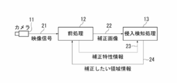
- FIG. 1 shows an example of the configuration of an intrusion detection system according to an embodiment of the present invention.
- the video signal 21 is obtained from the camera 11 that captures the monitoring area
- the input image is acquired at every predetermined frame interval
- the input image is contrast-enhanced by the preprocessing unit 12, and obtained as a result.
- the intrusion detection processing unit 13 By analyzing the corrected image 22 by the intrusion detection processing unit 13, the accuracy of detecting an intruder in the monitoring area is improved.
- FIG. 2 shows an example of a hardware configuration of an intrusion detection device (an example of the object detection device according to the present invention) that is integrally provided with the preprocessing unit 12 and the intrusion detection processing unit 13. Note that each of the preprocessing unit 12 and the intrusion detection processing unit 13 may be provided in a separate device that can communicate with each other.
- the intrusion detection apparatus of this example converts the analog video signal 21 obtained from the camera 11 into digital (A / D conversion), and has a predetermined number of gradations (256 gradations of 0 to 255 in this example).
- Image input I / F 31 for obtaining an input image expressed by a luminance signal
- an image memory 32 used for calculation and storage between images
- image analysis processing including processing contents by the preprocessing unit 12 and the intrusion detection processing unit 13 CPU (Central Processing Unit) 33
- input / output I / F 34 for receiving command signals from the outside and transmitting alarm signals to the outside
- work memory 35 serving as a work area for the CPU 33
- the above image analysis processing Convert the digital image stored in the program memory 36 and the image memory 32 into analog video signals (D / A conversion)
- External (e.g., a monitoring monitor) image output I / F 37 for outputting to be realized by a computer having a data bus 38 for transferring data between these functional units 31-37.
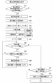
- the pre-processing unit 12 performs an input image capturing process (step S11). An input image obtained by A / D converting the video signal 21 from the camera 11 by the image input I / F unit 31 is converted into an image memory 32. In the input image memory area.
- step S12 it is determined whether or not the process is the first (first) process (for example, whether or not the process is the moment when the power is switched from OFF to ON).
- step S12 If it is determined as the first time in the initial determination process (step S12), the correction base image (whole) registration process (step S13), the background update rate request command output process (step S14), and the correction area initialization process (step S15). ). On the other hand, if it is determined in the initial determination process (step S12) that it is not the first time, these processes (steps S13 to S15) are skipped.
- the corrected base image (whole) registration process the input image stored in the input image memory area in the image memory 32 is copied to the corrected base image (whole) memory area in the image memory 32.
- a correction base image (entire) is obtained.
- a background update rate request command is output to the intrusion detection processing unit 13.
- the entire screen is set as a correction area that is a target of a contrast correction process (step S21) described later. The screen here corresponds to the input image.
- step S26 output image creation (no correction) processing (step S26) is executed.
- the output image creation (without correction) process step S26
- the input image stored in the input image memory area in the image memory 32 is copied to the output image memory area in the image memory 32, whereby the output image is converted. obtain.
- the output image creation (no correction) process step S26
- the process proceeds to a video output process (step S23) described later.
- step S17 the background update rate registration process (step S17) is executed.
- the background update rate registration process step S17
- the background update rate returned from the intrusion detection processing unit 13 is registered. If the background update rate has already been registered, the background update rate registration process (step S17) is skipped.
- step S18 it is determined whether or not the area information 24 to be corrected is received from the intrusion detection processing unit 13. If it is determined in the correction area reception determination process (step S18) that the area information 24 to be corrected has been received from the intrusion detection processing unit 13, a correction base image (only correction area) registration process (step S19), correction area registration A process (step S20) is executed.
- the correction base image (only correction area) registration process (step S19) the correction base image (entire) obtained in the correction base image (whole) registration process (step S13) is indicated by the area information 24 to be corrected. Only the correction area portion is cut out and copied to the correction base image (only correction area) memory area in the image memory 32 to obtain a correction base image (only correction area). Note that if contrast correction of the entire screen has been performed on the previous input image by contrast correction processing (step S21) described later, a correction area portion is cut out from the result, and the correction base is corrected. An image (only the correction area) is obtained. In the correction area registration process (step S20), the correction area indicated by the area information 24 to be corrected is registered as a correction area to be subjected to a contrast correction process (step S21) described later.
- step S21 the correction area registered in the correction area registration process (step S20), the correction base image (whole) registered in the correction base image (whole) registration process (step S13), and the correction base image.
- step S19 Registered in the correction base image (only correction area) registered in the registration process (step S19), input image captured in the input image capture process (step S11), and background update rate registration process (step S17)
- Contrast correction is performed using each data of the background update rate, and a contrast-corrected image as a result is obtained. Details of the processing will be described later.
- the contrast corrected image obtained in the contrast correction process (step S21) is copied to the output image memory area in the image memory 32, thereby obtaining an output image. Thereafter, in the video output process (step S23), the output image (contrast correction image or input image) stored in the output image memory area in the image memory 32 is output to the intrusion detection processing unit 13 as the corrected image 22.
- step S24 an elapsed time from the previous command transmission is determined in a command output interval determination process (step S24). If it is determined in the command output interval determination process (step S24) that the elapsed time from the previous command transmission is less than the specified time (T seconds), the process returns to the input image capture process (step S11).
- the correction characteristic information 23 is output to the intrusion detection processing unit 13.
- the correction characteristic information 23 stores information indicating image characteristics related to contrast correction (emphasis). Note that it is considered that the output of the correction characteristic information 23 is sufficient once every several seconds, considering that the rate of change in luminance level between frames is small and that no load is applied to command transmission / reception.
- FIG. 4 shows the basic contrast enhancement.
- the appearance frequency (the number of corresponding pixels) is calculated for each luminance level (256 gradations of 0 to 255 in this example).
- the histogram illustrated in FIG. 4B is obtained.
- the cumulative frequency is calculated for each luminance level.
- the cumulative frequency for each luminance level is calculated as follows.
- Cumulative frequency (0) Frequency of luminance (0)
- Cumulative frequency (1) Frequency of luminance (0) + Frequency of luminance (1)
- Cumulative frequency (127) frequency of luminance (0) to total frequency of luminance (127)
- Cumulative frequency (255) frequency of luminance (0) to total frequency of luminance (255)
- a graph of the cumulative frequency for each luminance level is the cumulative frequency graph illustrated in FIG. 4C.
- the minimum value and the maximum value of the cumulative frequency are calculated from the cumulative frequency for each luminance level.
- the minimum value is the value of the rising portion (cumulative frequency) greater than the cumulative frequency (0)
- the luminance value (luminance level) is converted by (Equation 1) for each pixel of the input image using the cumulative frequency for each luminance level and the minimum and maximum values of the cumulative frequency obtained by the above procedure.
- I [i, j] is the luminance value of each pixel before contrast enhancement
- O [i, j] is the luminance value of each pixel after contrast enhancement
- D (I [i, j]) is the cumulative frequency of the luminance value of I [i, j]
- D min (H) is the minimum cumulative frequency
- Diff is the maximum cumulative frequency. Value-the minimum cumulative frequency.
- step S21 the process (contrast enhancement) described with reference to FIG. 3 is performed based on the region information 24 to be corrected from the intrusion detection processing unit 13. That is, contrast enhancement is performed on each correction area indicated by the area information 24 to be corrected, and the resulting contrast-enhanced image of each correction area is copied to the input image, so that the entire screen or a part of the screen is displayed. It is possible to obtain a contrast-corrected image (corrected image 22) that is the result of performing contrast enhancement on the image.
- the entire screen and a part of the screen may be specified together.
- the contrast enhancement for the entire screen and the contrast enhancement for a part of the screen are performed, respectively. Copy the entire contrast-enhanced image to the input image (overall replacement), and then copy the partial contrast-enhanced image to the corresponding screen part (partial replacement).
- a contrast-corrected image (corrected image 22) subjected to partial contrast enhancement can be obtained.
- contrast enhancement is performed on the entire screen, and the resulting contrast-enhanced image on the entire screen is further subjected to contrast enhancement on a portion of the screen to obtain a contrast-corrected image (corrected image). 22) may be more suitable for intrusion detection by the subsequent intrusion detection processing unit 13.
- the luminance is not only in the part where the intruder exists but also in the background part such as a building.
- the level changes greatly. Therefore, in this example, instead of simply copying the contrast-enhanced image to obtain the contrast-corrected image (corrected image 22), the weighted average of the corrected base image and the contrast-enhanced image is calculated by the following (Equation 2).
- Equation 2 a contrast-corrected image (corrected image 22) is created and used for intrusion detection by the intrusion detection processing unit 13, thereby preventing erroneous detection of a background such as a building.
- Contrast correction image correction base image ⁇ (1 ⁇ background update rate) + Contrast-enhanced image ⁇ background update rate (Equation 2) That is, a contrast-corrected image in which the contribution rate of the post-contrast-enhanced image is increased as the background update rate increases.
- a histogram is created again for the contrast-corrected image (corrected image 22), and the width of the section where the cumulative frequency does not occur (the falling portion of the cumulative frequency).
- the maximum level width which is the maximum value between the rising portion and the rising portion).
- the maximum level width represents the maximum noise level generated by histogram enhancement, is stored in the correction characteristic information 23 and is output to the intrusion detection processing unit 13, and the intrusion detection processing unit 13 is used to determine the binarization threshold value in the process of No. 13.
- the correction characteristic information 23 also stores the minimum luminance, the maximum luminance, the maximum level difference, and the like as other information indicating the image characteristic relating to the contrast correction (enhancement).
- the minimum luminance is a luminance level at which the cumulative frequency becomes a minimum value before contrast enhancement
- the maximum luminance is a luminance level at which the cumulative frequency becomes a maximum value before contrast enhancement.
- the maximum level difference is the maximum value of the luminance level in the difference between the contrast corrected image (corrected image 22) and the image after contrast enhancement.
- the intrusion detection processing unit 13 first creates a background image used for intrusion detection in a background image creation process (step S31).
- a background image a weighted average of a plurality of input images (corrected images 22) that are different in time is taken to create an image in a state in which an object (intruder) to be detected does not exist.
- the background image can be created by using, for example, the technique disclosed in Japanese Patent Application Laid-Open No. 2009-282975.
- a new input image (corrected image 22) is captured by the input image capture processing (step S32).
- a background update rate request command reception determination process (step S33) it is determined whether or not a background update rate request command has been received from the preprocessing unit 12. If it is determined in the background update rate request command reception determination process (step S33) that the background update rate request command has been received, a background update rate response command output process (step S34) is executed. On the other hand, if it is determined in the background update rate request command reception determination process (step S33) that the background update rate request command has not been received, the background update rate response command output process (step S34) is skipped.
- the background update rate response command output process (step S34) the background update rate is notified to the preprocessing unit 12 as a response to the background update rate request command. Since the background update rate request command is output only once when the preprocessing unit 12 is activated, the background update rate response command output process (step S34) is performed at an interval (basically 1). Executed only once).
- the background update rate is a value calculated by comparing the background image at the time of the previous background update rate request command and the background image at the current time (at the time of the current background update rate request command), Represents the degree of background image difference.
- step S35 it is determined whether or not the correction characteristic information 23 has been received from the preprocessing unit 12. If it is determined in the correction characteristic information reception determination process (step S35) that the correction characteristic information 23 has been received, a binarization threshold value registration process (step S36) is executed. On the other hand, if it is determined in the correction characteristic information reception determination process (step S35) that the correction characteristic information 23 has not been received, the binarization threshold value registration process (step S36) is skipped.
- the maximum level width indicated by the correction characteristic information 23 is registered as the binarization threshold value.
- binarization threshold value By setting the binarization threshold value to the maximum level width, binarization is performed with a threshold value equal to or higher than the noise level, so that the influence of noise can be eliminated. Since the detection level of the object is emphasized more than the noise level, there is no influence of oversight by this processing.
- the maximum level width itself is used as a binarization threshold value.
- the present invention is not limited to this, and a value adjusted by multiplying the maximum level width by a predetermined coefficient may be used. It suffices if it is possible to effectively eliminate the influence of.
- a difference process (step S37), a binarization process (step S38), a noise removal process (step S39), and a labeling process (step S40) are executed.
- the difference process (step S37) the difference between the background image obtained in the background image creation process (step S31) and the input image (corrected image 22) obtained in the input image capture process (step S32) is calculated.
- a difference image (input image-background image) is created.
- the difference between the input image (corrected image 22) and the background image may be calculated with a sign or may be calculated as an absolute value.
- background image update processing (step S44) described later is performed, a difference image is created using the background image updated by the background image update processing (step S44).
- the difference image obtained in the difference process (step S37) is binarized by the binarization threshold value registered in the binarization threshold value registration process (step S36).
- Create a binary image That is, a binary image is created by setting the luminance value of pixels below the binarization threshold to 0 and the luminance value of pixels above the binarization threshold to 255.
- noise removal process step S39
- noise included in the binary image created in the binarization process (step S38) is removed, and a noise-removed image is created. In this example, a pixel group less than a predetermined number of pixels included in the binary image is removed as noise.
- a pixel block remaining in the noise-removed image created in the noise removal process is regarded as an object and labeled for each object (chunk) (identification information is given). Then, the width, height, and area of each object are calculated.
- the type of the object is determined for each object obtained in the labeling process (step S40) based on the size of the object, the staying time, the moving distance, and the like.
- the size of the object can be specified based on, for example, the width, height, and area of the object obtained by the labeling process (step S40).
- the staying time of the object can be specified based on the number of input images (number of frames) in which the object is detected among a plurality of input images that are temporally different.
- the moving distance of the object can be specified based on, for example, position information of the object in a plurality of input images that are temporally different.
- step S42 it is determined whether or not the object determined in the object determination process (step S41) is a person (intruder).
- step S43 an alarm is output from an external device such as turning on Patlite (registered trademark), sounding a buzzer, or notifying the server.
- background image update processing step S44
- video display processing step S45
- correction necessary area calculation processing step S46
- the background image is updated.
- the background image is updated every time an input image (corrected image 22) is captured in order to follow a video state that changes every moment.
- the input image (corrected image 22) is D / A converted by the image output I / F 37, and is output and displayed on a monitor or the like monitored by the supervisor. If there is an intruder, a character “intruder detection”, a marker indicating the detection location, etc. (an image with intruder information) superimposed on the input image (corrected image 22) is output to the monitor.
- step S46 the presence or absence of an area that is locally in a low contrast state due to the presence of a person in black clothes in a dark part is checked, and the corresponding area (in a low contrast state) (Region) information is stored in the region information 24 to be corrected and transmitted to the preprocessing unit 12. Thereby, it is possible to perform contrast enhancement on a portion where a low contrast state is locally generated.
- step S46 it is determined whether or not it is necessary to perform contrast correction (contrast enhancement) on the entire screen in a correction necessity determination process (step S51). Specifically, a luminance difference that is a difference between the minimum luminance and the maximum luminance indicated by the correction characteristic information 23 is calculated, the luminance difference is small (that is, the luminance difference is less than a predetermined reference difference value), and If the entire screen is not registered as a correction area, it is determined that contrast correction of the entire screen is necessary.
- step S51 When it is determined in the correction necessity determination process (step S51) that the contrast correction of the entire screen is necessary, a correction area number increment process (step S52) and an entire correction area registration process (step S53) are executed. On the other hand, if it is determined in the correction necessity determination process (step S51) that the contrast correction of the entire screen is not necessary, the correction area number increment process (step S52) and the entire correction area registration process (step S53) are skipped. .
- the correction area number increment process (step S52), the correction area number n is incremented (+1).
- the correction area number n is set to 0 as an initial value.
- the entire correction area registration process (step S53), the entire screen is registered as the nth correction area.
- the luminance difference between the minimum luminance and the maximum luminance is not small (that is, the luminance difference is a predetermined reference). If the difference value is greater than or equal to the difference value, the entire screen is deleted from the correction area, and the number of correction areas is decremented ( ⁇ 1).
- binarization threshold value registration processing (step S54), binarization processing (step S55), correction area extraction processing (step S56), and labeling processing (step S57) are executed.
- a minimum threshold value necessary for calculating the correction required region is set in advance, and this minimum threshold value is registered as the binarization threshold value.
- a value lower (smaller) than the binarization threshold value registered in the binarization threshold value registration process (step S36) is used.
- the binarization process (step S55) the difference image obtained in the difference process (step S37) is binarized by the binarization threshold value registered in the binarization threshold value registration process (step S55). Create a binary image. That is, a binary image is created by setting the luminance value of pixels below the binarization threshold to 0 and the luminance value of pixels above the binarization threshold to 255.
- the binary image created in the binarization process is defined as a binary image A
- the binary image created in the binarization process is binarized.
- As the image B a difference between the binary image A and the binary image B is calculated, and a binary image C that is a difference image between the binary image A and the binary image B is created.
- a labeling process is performed on the binary image C obtained by the correction area extraction process (step S56), and a group of pixels included in the binary image C is regarded as an object. Label (add identification information) for each (group) and calculate the width, height, and area of the object.
- the post-labeling process number is initialized to 0, and it is determined whether or not the post-labeling process number is smaller than the number of labeling.
- the number of labels is the number of objects labeled in the labeling process (step S57). Further, the number of post-labeling processes is incremented (+1) each time the subsequent correction area determination process (step S59) is executed. That is, in the process number determination process (step S58), it is determined whether the correction area determination process (step S59) has been performed on all labeled objects.
- a correction area determination process (step S59) is executed.
- the correction area determination process it is determined whether or not it is necessary to perform contrast correction (contrast) for each object labeled in the labeling process (step S57). Specifically, when the area obtained by the labeling process (step S57) is large (that is, the area is equal to or larger than a predetermined reference area value) and is not registered as a correction area, the image portion of the object Is determined to require local contrast correction.
- a correction area increment process (step S60) and a local correction area registration process (step S61) are further executed.
- the correction area number increment process step S60
- the correction area number n is incremented (+1).
- the local correction area registration process as the nth correction area (local correction area), an area obtained by expanding the width and height obtained in the labeling process (step S57) by ⁇ specified values ( ⁇ %) Register (extended area).
- the number of pixels of the object obtained in the labeling process is small (that is, When the state where the number of pixels is less than the predetermined reference number of pixels continues for a specified time (several seconds), the area corresponding to the object (extended area) is deleted from the correction area, and the number of correction areas is decremented ( ⁇ 1) To do.
- Correction area addition / deletion determination processing (step S62) is executed.
- the number of correction areas of the preprocessed frame preprocessed frame
- the number of correction areas of the current process frame currently processed input image
- a correction area information output process (step S64) is executed. On the other hand, if it is determined in the correction area addition / deletion determination process (step S62) that there is no change in the number of correction areas, the correction area information output process (step S64) is skipped. In the correction area information output process (step S64), information on the area registered as the correction area is transmitted as the area information 24 to be corrected to the preprocessing unit 12. With the above processing, contrast enhancement suitable for intrusion detection can be performed.
- the configuration of the system and apparatus according to the present invention is not necessarily limited to the configuration described above, and various configurations may be used.
- the present invention can also be provided as, for example, a method or method for executing the processing according to the present invention, a program for realizing such a method or method, or a recording medium for recording the program. It is also possible to provide various systems and devices.
- the application field of the present invention is not necessarily limited to the above-described fields, and the present invention can be applied to various fields.
- the processor executes a control program stored in a ROM (Read Only Memory) in hardware resources including a processor and a memory.
- ROM Read Only Memory
- a controlled configuration may be used, and for example, each functional unit for executing the processing may be configured as an independent hardware circuit.
- the present invention can be grasped as a computer-readable recording medium such as a floppy (registered trademark) disk or a CD (Compact Disc) -ROM storing the control program, or the program (itself).
- the processing according to the present invention can be performed by inputting the program from the recording medium to the computer and causing the processor to execute the program.
- the present invention functions effectively when the field of view is not good due to fog, haze or smoke, and is also effective in a normal image monitoring system. Further, the present invention is not limited to the image monitoring field, and can be applied to any system that browses images.
Landscapes
- Engineering & Computer Science (AREA)
- Physics & Mathematics (AREA)
- General Physics & Mathematics (AREA)
- Theoretical Computer Science (AREA)
- Multimedia (AREA)
- Computer Vision & Pattern Recognition (AREA)
- Human Computer Interaction (AREA)
- Image Analysis (AREA)
- Burglar Alarm Systems (AREA)
- Closed-Circuit Television Systems (AREA)
- Alarm Systems (AREA)
Priority Applications (2)
| Application Number | Priority Date | Filing Date | Title |
|---|---|---|---|
| GB1415683.0A GB2514301B (en) | 2012-03-07 | 2012-11-30 | Object detection device, object detection method and program |
| US14/378,388 US9443150B2 (en) | 2012-03-07 | 2012-11-30 | Device and method for detecting objects from a video signal |
Applications Claiming Priority (2)
| Application Number | Priority Date | Filing Date | Title |
|---|---|---|---|
| JP2012-050396 | 2012-03-07 | ||
| JP2012050396A JP5950628B2 (ja) | 2012-03-07 | 2012-03-07 | 物体検知装置、物体検知方法及びプログラム |
Publications (1)
| Publication Number | Publication Date |
|---|---|
| WO2013132711A1 true WO2013132711A1 (ja) | 2013-09-12 |
Family
ID=49116210
Family Applications (1)
| Application Number | Title | Priority Date | Filing Date |
|---|---|---|---|
| PCT/JP2012/081144 Ceased WO2013132711A1 (ja) | 2012-03-07 | 2012-11-30 | 物体検知装置、物体検知方法及びプログラム |
Country Status (4)
| Country | Link |
|---|---|
| US (1) | US9443150B2 (https=) |
| JP (1) | JP5950628B2 (https=) |
| GB (1) | GB2514301B (https=) |
| WO (1) | WO2013132711A1 (https=) |
Families Citing this family (5)
| Publication number | Priority date | Publication date | Assignee | Title |
|---|---|---|---|---|
| US20160371847A1 (en) * | 2014-07-24 | 2016-12-22 | Bonanza.com, LLC | Background profiles |
| US20170034459A1 (en) * | 2015-07-30 | 2017-02-02 | Motorola Mobility Llc | Electronic Device with Image Correction System and Methods Therefor |
| US20180352177A1 (en) * | 2015-09-18 | 2018-12-06 | Hitachi Kokusai Electric Inc. | Image-processing device |
| US11516385B2 (en) * | 2020-12-09 | 2022-11-29 | Microsoft Technology Licensing, Llc | Dynamic quality proxy plural camera image blending |
| CN112530216B (zh) * | 2020-12-16 | 2022-06-21 | 北京新大陆时代教育科技有限公司 | 一种沉浸式虚实交互的实训系统及其方法 |
Citations (4)
| Publication number | Priority date | Publication date | Assignee | Title |
|---|---|---|---|---|
| JPH04213195A (ja) * | 1990-12-06 | 1992-08-04 | Japan Radio Co Ltd | 侵入者監視システム |
| JPH08171689A (ja) * | 1994-12-19 | 1996-07-02 | Kansai Electric Power Co Inc:The | 変化領域検出装置 |
| JP2001197483A (ja) * | 2000-01-12 | 2001-07-19 | Yokogawa Electric Corp | 画像処理手段を用いた設備監視システム |
| JP2005115932A (ja) * | 2003-09-16 | 2005-04-28 | Matsushita Electric Works Ltd | 画像を用いた人体検知装置 |
Family Cites Families (12)
| Publication number | Priority date | Publication date | Assignee | Title |
|---|---|---|---|---|
| KR100763239B1 (ko) * | 2006-06-27 | 2007-10-04 | 삼성전자주식회사 | 디스플레이되는 영상의 시인성 향상을 위한 영상 처리 장치및 방법 |
| US8432448B2 (en) * | 2006-08-10 | 2013-04-30 | Northrop Grumman Systems Corporation | Stereo camera intrusion detection system |
| US8437566B2 (en) * | 2007-04-27 | 2013-05-07 | Microsemi Corporation | Software methodology for autonomous concealed object detection and threat assessment |
| JP5354767B2 (ja) * | 2007-10-17 | 2013-11-27 | 株式会社日立国際電気 | 物体検知装置 |
| JP5202551B2 (ja) * | 2009-01-23 | 2013-06-05 | 株式会社日立国際電気 | パラメータ設定方法及び該方法を用いた監視装置 |
| JP5260431B2 (ja) * | 2009-07-22 | 2013-08-14 | セコム株式会社 | 対象物検知装置 |
| JP5023203B2 (ja) * | 2010-08-24 | 2012-09-12 | 株式会社東芝 | 画像補正装置及び補正パラメータ作成装置 |
| JP5719141B2 (ja) * | 2010-10-28 | 2015-05-13 | キヤノン株式会社 | 情報処理装置、その処理方法及びプログラム |
| US20130170760A1 (en) * | 2011-12-29 | 2013-07-04 | Pelco, Inc. | Method and System for Video Composition |
| US9530221B2 (en) * | 2012-01-06 | 2016-12-27 | Pelco, Inc. | Context aware moving object detection |
| JP5948983B2 (ja) * | 2012-03-09 | 2016-07-06 | オムロン株式会社 | 画像処理装置、画像処理方法、および画像処理プログラム |
| US10373470B2 (en) * | 2013-04-29 | 2019-08-06 | Intelliview Technologies, Inc. | Object detection |
-
2012
- 2012-03-07 JP JP2012050396A patent/JP5950628B2/ja not_active Expired - Fee Related
- 2012-11-30 US US14/378,388 patent/US9443150B2/en not_active Expired - Fee Related
- 2012-11-30 WO PCT/JP2012/081144 patent/WO2013132711A1/ja not_active Ceased
- 2012-11-30 GB GB1415683.0A patent/GB2514301B/en active Active
Patent Citations (4)
| Publication number | Priority date | Publication date | Assignee | Title |
|---|---|---|---|---|
| JPH04213195A (ja) * | 1990-12-06 | 1992-08-04 | Japan Radio Co Ltd | 侵入者監視システム |
| JPH08171689A (ja) * | 1994-12-19 | 1996-07-02 | Kansai Electric Power Co Inc:The | 変化領域検出装置 |
| JP2001197483A (ja) * | 2000-01-12 | 2001-07-19 | Yokogawa Electric Corp | 画像処理手段を用いた設備監視システム |
| JP2005115932A (ja) * | 2003-09-16 | 2005-04-28 | Matsushita Electric Works Ltd | 画像を用いた人体検知装置 |
Also Published As
| Publication number | Publication date |
|---|---|
| JP5950628B2 (ja) | 2016-07-13 |
| GB201415683D0 (en) | 2014-10-22 |
| JP2013186635A (ja) | 2013-09-19 |
| GB2514301B (en) | 2016-06-22 |
| US20150043775A1 (en) | 2015-02-12 |
| US9443150B2 (en) | 2016-09-13 |
| GB2514301A (en) | 2014-11-19 |
Similar Documents
| Publication | Publication Date | Title |
|---|---|---|
| KR101375583B1 (ko) | 비디오에서의 물체 조밀도 판단 | |
| US6754367B1 (en) | Method and apparatus for automatically detecting intrusion object into view of image pickup device | |
| JP5241782B2 (ja) | カメラ異常検出装置を有する監視カメラシステム | |
| US7778445B2 (en) | Method and system for the detection of removed objects in video images | |
| JP4203736B2 (ja) | 画像の動き検出装置及びコンピュータプログラム | |
| US10445590B2 (en) | Image processing apparatus and method and monitoring system | |
| JP5388829B2 (ja) | 侵入物体検知装置 | |
| JP5950628B2 (ja) | 物体検知装置、物体検知方法及びプログラム | |
| JP2013065151A (ja) | 画像処理装置、画像処理方法、および、プログラム | |
| JP2010015469A (ja) | 静止領域検出方法とその装置、プログラム及び記録媒体 | |
| KR100659781B1 (ko) | 씨씨디 영상에서의 연기 검출방법 및 장치 | |
| JP5710230B2 (ja) | 監視システムおよび監視方法 | |
| JP5142416B2 (ja) | 物体検出装置 | |
| JP2001160146A (ja) | 画像認識方法および画像認識装置 | |
| JPH1093957A (ja) | 移動物体検出方法、装置、システム、および記憶媒体 | |
| JP3736836B2 (ja) | 物体検出方法及び物体検出装置及びプログラム | |
| JP7233994B2 (ja) | 画像処理装置及び画像処理プログラム | |
| JP2002150440A (ja) | 監視対象物検出装置 | |
| JP2002218443A (ja) | 侵入物体検出のためのしきい値を自動的に決定する侵入物体検出方法及び侵入物体監視装置 | |
| WO2021014873A1 (ja) | 監視装置、監視方法、及びコンピュータ読み取り可能な記録媒体 | |
| KR101248154B1 (ko) | 가변크기 영역 기반의 객체 움직임 추정 방법 및 이를 실행하는 장치, 그리고 이를 실행하는 움직임 추정 프로그램을 기록한 컴퓨터로 판독가능한 기록매체 | |
| JP6124739B2 (ja) | 画像センサ | |
| JP2001169270A (ja) | 画像監視装置及び画像監視方法 | |
| JP4619082B2 (ja) | 画像判定装置 | |
| JP2004128648A (ja) | 侵入物体追尾方法 |
Legal Events
| Date | Code | Title | Description |
|---|---|---|---|
| 121 | Ep: the epo has been informed by wipo that ep was designated in this application |
Ref document number: 12870696 Country of ref document: EP Kind code of ref document: A1 |
|
| NENP | Non-entry into the national phase |
Ref country code: DE |
|
| WWE | Wipo information: entry into national phase |
Ref document number: 14378388 Country of ref document: US |
|
| ENP | Entry into the national phase |
Ref document number: 1415683 Country of ref document: GB Kind code of ref document: A Free format text: PCT FILING DATE = 20121130 |
|
| WWE | Wipo information: entry into national phase |
Ref document number: 1415683.0 Country of ref document: GB |
|
| 122 | Ep: pct application non-entry in european phase |
Ref document number: 12870696 Country of ref document: EP Kind code of ref document: A1 |