WO2013132711A1 - Object detection device, object detection method and program - Google Patents
Object detection device, object detection method and program Download PDFInfo
- Publication number
- WO2013132711A1 WO2013132711A1 PCT/JP2012/081144 JP2012081144W WO2013132711A1 WO 2013132711 A1 WO2013132711 A1 WO 2013132711A1 JP 2012081144 W JP2012081144 W JP 2012081144W WO 2013132711 A1 WO2013132711 A1 WO 2013132711A1
- Authority
- WO
- WIPO (PCT)
- Prior art keywords
- image
- correction
- input image
- object detection
- contrast
- Prior art date
Links
- 238000001514 detection method Methods 0.000 title claims abstract description 105
- 238000000034 method Methods 0.000 claims abstract description 174
- 238000012937 correction Methods 0.000 claims abstract description 165
- 238000007781 pre-processing Methods 0.000 claims abstract description 40
- 238000012544 monitoring process Methods 0.000 claims description 23
- 230000002708 enhancing effect Effects 0.000 claims description 2
- 238000012545 processing Methods 0.000 abstract description 69
- 239000003595 mist Substances 0.000 abstract 1
- 230000008569 process Effects 0.000 description 158
- 230000001186 cumulative effect Effects 0.000 description 27
- 238000002372 labelling Methods 0.000 description 20
- 230000004044 response Effects 0.000 description 8
- 230000005540 biological transmission Effects 0.000 description 4
- 230000008859 change Effects 0.000 description 4
- 238000006243 chemical reaction Methods 0.000 description 4
- 238000012217 deletion Methods 0.000 description 4
- 230000037430 deletion Effects 0.000 description 4
- 238000010191 image analysis Methods 0.000 description 4
- 230000000630 rising effect Effects 0.000 description 4
- 238000000605 extraction Methods 0.000 description 3
- 230000004913 activation Effects 0.000 description 2
- 230000001965 increasing effect Effects 0.000 description 2
- 239000003550 marker Substances 0.000 description 2
- 238000004458 analytical method Methods 0.000 description 1
- 230000008901 benefit Effects 0.000 description 1
- 230000006870 function Effects 0.000 description 1
- 230000014509 gene expression Effects 0.000 description 1
- 238000003384 imaging method Methods 0.000 description 1
- 239000000779 smoke Substances 0.000 description 1
- XLYOFNOQVPJJNP-UHFFFAOYSA-N water Substances O XLYOFNOQVPJJNP-UHFFFAOYSA-N 0.000 description 1
Images


Classifications
-
- G—PHYSICS
- G06—COMPUTING; CALCULATING OR COUNTING
- G06T—IMAGE DATA PROCESSING OR GENERATION, IN GENERAL
- G06T5/00—Image enhancement or restoration
- G06T5/90—Dynamic range modification of images or parts thereof
- G06T5/94—Dynamic range modification of images or parts thereof based on local image properties, e.g. for local contrast enhancement
-
- G—PHYSICS
- G06—COMPUTING; CALCULATING OR COUNTING
- G06T—IMAGE DATA PROCESSING OR GENERATION, IN GENERAL
- G06T5/00—Image enhancement or restoration
- G06T5/90—Dynamic range modification of images or parts thereof
- G06T5/92—Dynamic range modification of images or parts thereof based on global image properties
-
- G—PHYSICS
- G06—COMPUTING; CALCULATING OR COUNTING
- G06V—IMAGE OR VIDEO RECOGNITION OR UNDERSTANDING
- G06V20/00—Scenes; Scene-specific elements
- G06V20/50—Context or environment of the image
- G06V20/52—Surveillance or monitoring of activities, e.g. for recognising suspicious objects
-
- G—PHYSICS
- G06—COMPUTING; CALCULATING OR COUNTING
- G06V—IMAGE OR VIDEO RECOGNITION OR UNDERSTANDING
- G06V40/00—Recognition of biometric, human-related or animal-related patterns in image or video data
- G06V40/10—Human or animal bodies, e.g. vehicle occupants or pedestrians; Body parts, e.g. hands
-
- G—PHYSICS
- G08—SIGNALLING
- G08B—SIGNALLING OR CALLING SYSTEMS; ORDER TELEGRAPHS; ALARM SYSTEMS
- G08B13/00—Burglar, theft or intruder alarms
- G08B13/18—Actuation by interference with heat, light, or radiation of shorter wavelength; Actuation by intruding sources of heat, light, or radiation of shorter wavelength
- G08B13/189—Actuation by interference with heat, light, or radiation of shorter wavelength; Actuation by intruding sources of heat, light, or radiation of shorter wavelength using passive radiation detection systems
- G08B13/194—Actuation by interference with heat, light, or radiation of shorter wavelength; Actuation by intruding sources of heat, light, or radiation of shorter wavelength using passive radiation detection systems using image scanning and comparing systems
- G08B13/196—Actuation by interference with heat, light, or radiation of shorter wavelength; Actuation by intruding sources of heat, light, or radiation of shorter wavelength using passive radiation detection systems using image scanning and comparing systems using television cameras
- G08B13/19602—Image analysis to detect motion of the intruder, e.g. by frame subtraction
- G08B13/19604—Image analysis to detect motion of the intruder, e.g. by frame subtraction involving reference image or background adaptation with time to compensate for changing conditions, e.g. reference image update on detection of light level change
-
- G—PHYSICS
- G06—COMPUTING; CALCULATING OR COUNTING
- G06T—IMAGE DATA PROCESSING OR GENERATION, IN GENERAL
- G06T2207/00—Indexing scheme for image analysis or image enhancement
- G06T2207/10—Image acquisition modality
- G06T2207/10004—Still image; Photographic image
-
- G—PHYSICS
- G06—COMPUTING; CALCULATING OR COUNTING
- G06T—IMAGE DATA PROCESSING OR GENERATION, IN GENERAL
- G06T2207/00—Indexing scheme for image analysis or image enhancement
- G06T2207/20—Special algorithmic details
- G06T2207/20172—Image enhancement details
- G06T2207/20208—High dynamic range [HDR] image processing
-
- G—PHYSICS
- G06—COMPUTING; CALCULATING OR COUNTING
- G06T—IMAGE DATA PROCESSING OR GENERATION, IN GENERAL
- G06T2207/00—Indexing scheme for image analysis or image enhancement
- G06T2207/30—Subject of image; Context of image processing
- G06T2207/30196—Human being; Person
-
- G—PHYSICS
- G06—COMPUTING; CALCULATING OR COUNTING
- G06T—IMAGE DATA PROCESSING OR GENERATION, IN GENERAL
- G06T2207/00—Indexing scheme for image analysis or image enhancement
- G06T2207/30—Subject of image; Context of image processing
- G06T2207/30232—Surveillance
-
- H—ELECTRICITY
- H04—ELECTRIC COMMUNICATION TECHNIQUE
- H04N—PICTORIAL COMMUNICATION, e.g. TELEVISION
- H04N7/00—Television systems
- H04N7/18—Closed-circuit television [CCTV] systems, i.e. systems in which the video signal is not broadcast
Definitions
- the present invention relates to a technique for detecting an object appearing in a monitoring area based on an image obtained by imaging the monitoring area.
- an intrusion detection device (including an intruder) is detected by analyzing an input image based on a video signal from a camera that captures a monitoring area by an intrusion detection device and detecting an object appearing in the monitoring area. Monitoring for the presence or absence of is being carried out.
- the intrusion detection device converts an analog video signal obtained from a camera into digital (A / D conversion), and obtains an input image expressed by a luminance signal having a predetermined number of gradations, Image memory used for computation between images and image storage, CPU (Central Processing Unit) for image analysis processing, input / output I / F for receiving command signals from outside and transmitting alarm signals to outside , A work memory serving as a work area of the CPU, a program memory storing the above-described image analysis processing program, a digital image stored in the image memory is converted into an analog video signal (D / A conversion), and externally (for example, Realized by a computer having an image output I / F output to a monitor for monitoring) and a data bus for transferring data by these functional units That.
- the intrusion detection apparatus creates a background image used for intrusion detection.
- the background image is created using a plurality of input images obtained at predetermined frame intervals from the camera via the image input I / F. Specifically, by taking a weighted average of a plurality of input images that are different in time, an image in a state where an object (intruder) that is the object of detection does not exist is created. After completing the creation of the background image, the following object detection process and video display process are repeated each time a video signal (input image) is captured from the camera. Moreover, when an intruder (including an intruder) is detected, an alarm process is performed.
- a difference between the created background image and the newly captured input image is calculated to create a difference image (input image-background image), and the difference image is preliminarily binarized.
- a binary image is created by binarizing with a value, noise (a group of several pixels) contained in the binary image is removed to create a noise-removed image, and a block of pixels remaining in the noise-removed image is defined as an object.
- an alarm process is performed to output an alarm from an external device, such as turning on Patlite (registered trademark), sounding a buzzer, or notifying the server.
- an external device such as turning on Patlite (registered trademark), sounding a buzzer, or notifying the server.
- the background image is updated every time an input image is captured from the camera in order to follow a video state that changes every moment.
- the input image captured from the camera is output and displayed on the monitor or the like monitored by the monitor via the image output I / F.
- an “intruder detection” character, a marker indicating a detection location, or the like superimposed on the input image (image with intruder information) is output to the monitor.
- Patent Document 1 discloses a steady or temporary change in brightness, movement of leaves and water surfaces, attenuation due to snow and rain, and the like.
- An invention of an object detection method considering a case where it is applied to a complex security system and traffic analysis under a complicated disturbance is disclosed.
- the video signal (input image) obtained from the camera is processed as it is, so that when the contrast of the entire image is reduced due to fog, rain, etc., or black clothes with little contrast difference with the background in a dark place.
- the luminance difference between the background and the object may become equal to or less than the binarization threshold value, leading to overlooking of the object. Therefore, a technique that can stably detect an object even in such a situation is desired.
- contrast enhancement as a method for correcting an image when the contrast is lowered as a whole.
- the advantage of performing contrast enhancement is that an image in which an intruder can be easily detected can be obtained.
- noise on the image is also enhanced, so that there is a drawback that false alarms increase. Therefore, it is necessary to devise a technique for suppressing false alarms for the emphasized noise.
- the present invention has been made in view of the circumstances as described above, and proposes a technique capable of stably detecting an object even in a state where the contrast of an image is lowered entirely or partially. With the goal.
- the present invention provides a pre-processing unit that performs correction for enhancing contrast on an input image in an object detection device that detects an object appearing in the monitoring area based on an input image from a camera that images the monitoring area. And an object detection means for detecting an object appearing in the monitoring area using the input image corrected by the preprocessing means and correction characteristic information including image characteristics related to the correction. It is an object detection device.
- the present invention can also be realized by other modes such as a method implemented by such an object detection apparatus and a program thereof.
- preprocessing is added before the object detection processing, and a corrected image (an image in which contrast enhancement is performed on the input image) obtained by the preprocessing is used as an input image in the intrusion detection processing.
- a corrected image an image in which contrast enhancement is performed on the input image obtained by the preprocessing is used as an input image in the intrusion detection processing.
- the preprocessing corrects the input image based on the position of the object detected by the object detection process.
- the contrast is locally reduced, such as black objects in dark places. It is possible to cope with the situation and realize object detection that suppresses misreporting and false alarms.
- the object detection process updates the background image to be compared with the input image in the object detection every time the input image is captured, and the preprocessing updates the background image in the object detection process.
- the correction amount of the input image is adjusted according to the rate. That is, the preprocessing refers to the background update rate representing the background learning speed in the object detection process, and determines the correction amount (degree of contrast enhancement) in one frame at the background image learning speed in the object detection process.
- the preprocessing refers to the background update rate representing the background learning speed in the object detection process, and determines the correction amount (degree of contrast enhancement) in one frame at the background image learning speed in the object detection process.
- the correction characteristic information is the luminance of the falling portion of the cumulative frequency in the cumulative frequency obtained by accumulating the appearance frequency of each luminance level in the input image after correction for each luminance level.
- a maximum level width that is the maximum value of the width between the level and the luminance level of the rising portion, and the object detection processing is performed by using the binarized threshold value determined based on the maximum level width, and the input image after correction Is binarized and used to detect an object.
- the maximum level width represents the maximum noise level generated by the correction (contrast enhancement) of the input image, and the corrected input image binarized by the binarization threshold based on the maximum level width.
- an area that needs to be corrected is determined. Thereby, it is possible to perform contrast enhancement on a portion where a low contrast state is locally generated.
- FIG. 1 shows an example of the configuration of an intrusion detection system according to an embodiment of the present invention.
- the video signal 21 is obtained from the camera 11 that captures the monitoring area
- the input image is acquired at every predetermined frame interval
- the input image is contrast-enhanced by the preprocessing unit 12, and obtained as a result.
- the intrusion detection processing unit 13 By analyzing the corrected image 22 by the intrusion detection processing unit 13, the accuracy of detecting an intruder in the monitoring area is improved.
- FIG. 2 shows an example of a hardware configuration of an intrusion detection device (an example of the object detection device according to the present invention) that is integrally provided with the preprocessing unit 12 and the intrusion detection processing unit 13. Note that each of the preprocessing unit 12 and the intrusion detection processing unit 13 may be provided in a separate device that can communicate with each other.
- the intrusion detection apparatus of this example converts the analog video signal 21 obtained from the camera 11 into digital (A / D conversion), and has a predetermined number of gradations (256 gradations of 0 to 255 in this example).
- Image input I / F 31 for obtaining an input image expressed by a luminance signal
- an image memory 32 used for calculation and storage between images
- image analysis processing including processing contents by the preprocessing unit 12 and the intrusion detection processing unit 13 CPU (Central Processing Unit) 33
- input / output I / F 34 for receiving command signals from the outside and transmitting alarm signals to the outside
- work memory 35 serving as a work area for the CPU 33
- the above image analysis processing Convert the digital image stored in the program memory 36 and the image memory 32 into analog video signals (D / A conversion)
- External (e.g., a monitoring monitor) image output I / F 37 for outputting to be realized by a computer having a data bus 38 for transferring data between these functional units 31-37.
- the pre-processing unit 12 performs an input image capturing process (step S11). An input image obtained by A / D converting the video signal 21 from the camera 11 by the image input I / F unit 31 is converted into an image memory 32. In the input image memory area.
- step S12 it is determined whether or not the process is the first (first) process (for example, whether or not the process is the moment when the power is switched from OFF to ON).
- step S12 If it is determined as the first time in the initial determination process (step S12), the correction base image (whole) registration process (step S13), the background update rate request command output process (step S14), and the correction area initialization process (step S15). ). On the other hand, if it is determined in the initial determination process (step S12) that it is not the first time, these processes (steps S13 to S15) are skipped.
- the corrected base image (whole) registration process the input image stored in the input image memory area in the image memory 32 is copied to the corrected base image (whole) memory area in the image memory 32.
- a correction base image (entire) is obtained.
- a background update rate request command is output to the intrusion detection processing unit 13.
- the entire screen is set as a correction area that is a target of a contrast correction process (step S21) described later. The screen here corresponds to the input image.
- step S26 output image creation (no correction) processing (step S26) is executed.
- the output image creation (without correction) process step S26
- the input image stored in the input image memory area in the image memory 32 is copied to the output image memory area in the image memory 32, whereby the output image is converted. obtain.
- the output image creation (no correction) process step S26
- the process proceeds to a video output process (step S23) described later.
- step S17 the background update rate registration process (step S17) is executed.
- the background update rate registration process step S17
- the background update rate returned from the intrusion detection processing unit 13 is registered. If the background update rate has already been registered, the background update rate registration process (step S17) is skipped.
- step S18 it is determined whether or not the area information 24 to be corrected is received from the intrusion detection processing unit 13. If it is determined in the correction area reception determination process (step S18) that the area information 24 to be corrected has been received from the intrusion detection processing unit 13, a correction base image (only correction area) registration process (step S19), correction area registration A process (step S20) is executed.
- the correction base image (only correction area) registration process (step S19) the correction base image (entire) obtained in the correction base image (whole) registration process (step S13) is indicated by the area information 24 to be corrected. Only the correction area portion is cut out and copied to the correction base image (only correction area) memory area in the image memory 32 to obtain a correction base image (only correction area). Note that if contrast correction of the entire screen has been performed on the previous input image by contrast correction processing (step S21) described later, a correction area portion is cut out from the result, and the correction base is corrected. An image (only the correction area) is obtained. In the correction area registration process (step S20), the correction area indicated by the area information 24 to be corrected is registered as a correction area to be subjected to a contrast correction process (step S21) described later.
- step S21 the correction area registered in the correction area registration process (step S20), the correction base image (whole) registered in the correction base image (whole) registration process (step S13), and the correction base image.
- step S19 Registered in the correction base image (only correction area) registered in the registration process (step S19), input image captured in the input image capture process (step S11), and background update rate registration process (step S17)
- Contrast correction is performed using each data of the background update rate, and a contrast-corrected image as a result is obtained. Details of the processing will be described later.
- the contrast corrected image obtained in the contrast correction process (step S21) is copied to the output image memory area in the image memory 32, thereby obtaining an output image. Thereafter, in the video output process (step S23), the output image (contrast correction image or input image) stored in the output image memory area in the image memory 32 is output to the intrusion detection processing unit 13 as the corrected image 22.
- step S24 an elapsed time from the previous command transmission is determined in a command output interval determination process (step S24). If it is determined in the command output interval determination process (step S24) that the elapsed time from the previous command transmission is less than the specified time (T seconds), the process returns to the input image capture process (step S11).
- the correction characteristic information 23 is output to the intrusion detection processing unit 13.
- the correction characteristic information 23 stores information indicating image characteristics related to contrast correction (emphasis). Note that it is considered that the output of the correction characteristic information 23 is sufficient once every several seconds, considering that the rate of change in luminance level between frames is small and that no load is applied to command transmission / reception.
- FIG. 4 shows the basic contrast enhancement.
- the appearance frequency (the number of corresponding pixels) is calculated for each luminance level (256 gradations of 0 to 255 in this example).
- the histogram illustrated in FIG. 4B is obtained.
- the cumulative frequency is calculated for each luminance level.
- the cumulative frequency for each luminance level is calculated as follows.
- Cumulative frequency (0) Frequency of luminance (0)
- Cumulative frequency (1) Frequency of luminance (0) + Frequency of luminance (1)
- Cumulative frequency (127) frequency of luminance (0) to total frequency of luminance (127)
- Cumulative frequency (255) frequency of luminance (0) to total frequency of luminance (255)
- a graph of the cumulative frequency for each luminance level is the cumulative frequency graph illustrated in FIG. 4C.
- the minimum value and the maximum value of the cumulative frequency are calculated from the cumulative frequency for each luminance level.
- the minimum value is the value of the rising portion (cumulative frequency) greater than the cumulative frequency (0)
- the luminance value (luminance level) is converted by (Equation 1) for each pixel of the input image using the cumulative frequency for each luminance level and the minimum and maximum values of the cumulative frequency obtained by the above procedure.
- I [i, j] is the luminance value of each pixel before contrast enhancement
- O [i, j] is the luminance value of each pixel after contrast enhancement
- D (I [i, j]) is the cumulative frequency of the luminance value of I [i, j]
- D min (H) is the minimum cumulative frequency
- Diff is the maximum cumulative frequency. Value-the minimum cumulative frequency.
- step S21 the process (contrast enhancement) described with reference to FIG. 3 is performed based on the region information 24 to be corrected from the intrusion detection processing unit 13. That is, contrast enhancement is performed on each correction area indicated by the area information 24 to be corrected, and the resulting contrast-enhanced image of each correction area is copied to the input image, so that the entire screen or a part of the screen is displayed. It is possible to obtain a contrast-corrected image (corrected image 22) that is the result of performing contrast enhancement on the image.
- the entire screen and a part of the screen may be specified together.
- the contrast enhancement for the entire screen and the contrast enhancement for a part of the screen are performed, respectively. Copy the entire contrast-enhanced image to the input image (overall replacement), and then copy the partial contrast-enhanced image to the corresponding screen part (partial replacement).
- a contrast-corrected image (corrected image 22) subjected to partial contrast enhancement can be obtained.
- contrast enhancement is performed on the entire screen, and the resulting contrast-enhanced image on the entire screen is further subjected to contrast enhancement on a portion of the screen to obtain a contrast-corrected image (corrected image). 22) may be more suitable for intrusion detection by the subsequent intrusion detection processing unit 13.
- the luminance is not only in the part where the intruder exists but also in the background part such as a building.
- the level changes greatly. Therefore, in this example, instead of simply copying the contrast-enhanced image to obtain the contrast-corrected image (corrected image 22), the weighted average of the corrected base image and the contrast-enhanced image is calculated by the following (Equation 2).
- Equation 2 a contrast-corrected image (corrected image 22) is created and used for intrusion detection by the intrusion detection processing unit 13, thereby preventing erroneous detection of a background such as a building.
- Contrast correction image correction base image ⁇ (1 ⁇ background update rate) + Contrast-enhanced image ⁇ background update rate (Equation 2) That is, a contrast-corrected image in which the contribution rate of the post-contrast-enhanced image is increased as the background update rate increases.
- a histogram is created again for the contrast-corrected image (corrected image 22), and the width of the section where the cumulative frequency does not occur (the falling portion of the cumulative frequency).
- the maximum level width which is the maximum value between the rising portion and the rising portion).
- the maximum level width represents the maximum noise level generated by histogram enhancement, is stored in the correction characteristic information 23 and is output to the intrusion detection processing unit 13, and the intrusion detection processing unit 13 is used to determine the binarization threshold value in the process of No. 13.
- the correction characteristic information 23 also stores the minimum luminance, the maximum luminance, the maximum level difference, and the like as other information indicating the image characteristic relating to the contrast correction (enhancement).
- the minimum luminance is a luminance level at which the cumulative frequency becomes a minimum value before contrast enhancement
- the maximum luminance is a luminance level at which the cumulative frequency becomes a maximum value before contrast enhancement.
- the maximum level difference is the maximum value of the luminance level in the difference between the contrast corrected image (corrected image 22) and the image after contrast enhancement.
- the intrusion detection processing unit 13 first creates a background image used for intrusion detection in a background image creation process (step S31).
- a background image a weighted average of a plurality of input images (corrected images 22) that are different in time is taken to create an image in a state in which an object (intruder) to be detected does not exist.
- the background image can be created by using, for example, the technique disclosed in Japanese Patent Application Laid-Open No. 2009-282975.
- a new input image (corrected image 22) is captured by the input image capture processing (step S32).
- a background update rate request command reception determination process (step S33) it is determined whether or not a background update rate request command has been received from the preprocessing unit 12. If it is determined in the background update rate request command reception determination process (step S33) that the background update rate request command has been received, a background update rate response command output process (step S34) is executed. On the other hand, if it is determined in the background update rate request command reception determination process (step S33) that the background update rate request command has not been received, the background update rate response command output process (step S34) is skipped.
- the background update rate response command output process (step S34) the background update rate is notified to the preprocessing unit 12 as a response to the background update rate request command. Since the background update rate request command is output only once when the preprocessing unit 12 is activated, the background update rate response command output process (step S34) is performed at an interval (basically 1). Executed only once).
- the background update rate is a value calculated by comparing the background image at the time of the previous background update rate request command and the background image at the current time (at the time of the current background update rate request command), Represents the degree of background image difference.
- step S35 it is determined whether or not the correction characteristic information 23 has been received from the preprocessing unit 12. If it is determined in the correction characteristic information reception determination process (step S35) that the correction characteristic information 23 has been received, a binarization threshold value registration process (step S36) is executed. On the other hand, if it is determined in the correction characteristic information reception determination process (step S35) that the correction characteristic information 23 has not been received, the binarization threshold value registration process (step S36) is skipped.
- the maximum level width indicated by the correction characteristic information 23 is registered as the binarization threshold value.
- binarization threshold value By setting the binarization threshold value to the maximum level width, binarization is performed with a threshold value equal to or higher than the noise level, so that the influence of noise can be eliminated. Since the detection level of the object is emphasized more than the noise level, there is no influence of oversight by this processing.
- the maximum level width itself is used as a binarization threshold value.
- the present invention is not limited to this, and a value adjusted by multiplying the maximum level width by a predetermined coefficient may be used. It suffices if it is possible to effectively eliminate the influence of.
- a difference process (step S37), a binarization process (step S38), a noise removal process (step S39), and a labeling process (step S40) are executed.
- the difference process (step S37) the difference between the background image obtained in the background image creation process (step S31) and the input image (corrected image 22) obtained in the input image capture process (step S32) is calculated.
- a difference image (input image-background image) is created.
- the difference between the input image (corrected image 22) and the background image may be calculated with a sign or may be calculated as an absolute value.
- background image update processing (step S44) described later is performed, a difference image is created using the background image updated by the background image update processing (step S44).
- the difference image obtained in the difference process (step S37) is binarized by the binarization threshold value registered in the binarization threshold value registration process (step S36).
- Create a binary image That is, a binary image is created by setting the luminance value of pixels below the binarization threshold to 0 and the luminance value of pixels above the binarization threshold to 255.
- noise removal process step S39
- noise included in the binary image created in the binarization process (step S38) is removed, and a noise-removed image is created. In this example, a pixel group less than a predetermined number of pixels included in the binary image is removed as noise.
- a pixel block remaining in the noise-removed image created in the noise removal process is regarded as an object and labeled for each object (chunk) (identification information is given). Then, the width, height, and area of each object are calculated.
- the type of the object is determined for each object obtained in the labeling process (step S40) based on the size of the object, the staying time, the moving distance, and the like.
- the size of the object can be specified based on, for example, the width, height, and area of the object obtained by the labeling process (step S40).
- the staying time of the object can be specified based on the number of input images (number of frames) in which the object is detected among a plurality of input images that are temporally different.
- the moving distance of the object can be specified based on, for example, position information of the object in a plurality of input images that are temporally different.
- step S42 it is determined whether or not the object determined in the object determination process (step S41) is a person (intruder).
- step S43 an alarm is output from an external device such as turning on Patlite (registered trademark), sounding a buzzer, or notifying the server.
- background image update processing step S44
- video display processing step S45
- correction necessary area calculation processing step S46
- the background image is updated.
- the background image is updated every time an input image (corrected image 22) is captured in order to follow a video state that changes every moment.
- the input image (corrected image 22) is D / A converted by the image output I / F 37, and is output and displayed on a monitor or the like monitored by the supervisor. If there is an intruder, a character “intruder detection”, a marker indicating the detection location, etc. (an image with intruder information) superimposed on the input image (corrected image 22) is output to the monitor.
- step S46 the presence or absence of an area that is locally in a low contrast state due to the presence of a person in black clothes in a dark part is checked, and the corresponding area (in a low contrast state) (Region) information is stored in the region information 24 to be corrected and transmitted to the preprocessing unit 12. Thereby, it is possible to perform contrast enhancement on a portion where a low contrast state is locally generated.
- step S46 it is determined whether or not it is necessary to perform contrast correction (contrast enhancement) on the entire screen in a correction necessity determination process (step S51). Specifically, a luminance difference that is a difference between the minimum luminance and the maximum luminance indicated by the correction characteristic information 23 is calculated, the luminance difference is small (that is, the luminance difference is less than a predetermined reference difference value), and If the entire screen is not registered as a correction area, it is determined that contrast correction of the entire screen is necessary.
- step S51 When it is determined in the correction necessity determination process (step S51) that the contrast correction of the entire screen is necessary, a correction area number increment process (step S52) and an entire correction area registration process (step S53) are executed. On the other hand, if it is determined in the correction necessity determination process (step S51) that the contrast correction of the entire screen is not necessary, the correction area number increment process (step S52) and the entire correction area registration process (step S53) are skipped. .
- the correction area number increment process (step S52), the correction area number n is incremented (+1).
- the correction area number n is set to 0 as an initial value.
- the entire correction area registration process (step S53), the entire screen is registered as the nth correction area.
- the luminance difference between the minimum luminance and the maximum luminance is not small (that is, the luminance difference is a predetermined reference). If the difference value is greater than or equal to the difference value, the entire screen is deleted from the correction area, and the number of correction areas is decremented ( ⁇ 1).
- binarization threshold value registration processing (step S54), binarization processing (step S55), correction area extraction processing (step S56), and labeling processing (step S57) are executed.
- a minimum threshold value necessary for calculating the correction required region is set in advance, and this minimum threshold value is registered as the binarization threshold value.
- a value lower (smaller) than the binarization threshold value registered in the binarization threshold value registration process (step S36) is used.
- the binarization process (step S55) the difference image obtained in the difference process (step S37) is binarized by the binarization threshold value registered in the binarization threshold value registration process (step S55). Create a binary image. That is, a binary image is created by setting the luminance value of pixels below the binarization threshold to 0 and the luminance value of pixels above the binarization threshold to 255.
- the binary image created in the binarization process is defined as a binary image A
- the binary image created in the binarization process is binarized.
- As the image B a difference between the binary image A and the binary image B is calculated, and a binary image C that is a difference image between the binary image A and the binary image B is created.
- a labeling process is performed on the binary image C obtained by the correction area extraction process (step S56), and a group of pixels included in the binary image C is regarded as an object. Label (add identification information) for each (group) and calculate the width, height, and area of the object.
- the post-labeling process number is initialized to 0, and it is determined whether or not the post-labeling process number is smaller than the number of labeling.
- the number of labels is the number of objects labeled in the labeling process (step S57). Further, the number of post-labeling processes is incremented (+1) each time the subsequent correction area determination process (step S59) is executed. That is, in the process number determination process (step S58), it is determined whether the correction area determination process (step S59) has been performed on all labeled objects.
- a correction area determination process (step S59) is executed.
- the correction area determination process it is determined whether or not it is necessary to perform contrast correction (contrast) for each object labeled in the labeling process (step S57). Specifically, when the area obtained by the labeling process (step S57) is large (that is, the area is equal to or larger than a predetermined reference area value) and is not registered as a correction area, the image portion of the object Is determined to require local contrast correction.
- a correction area increment process (step S60) and a local correction area registration process (step S61) are further executed.
- the correction area number increment process step S60
- the correction area number n is incremented (+1).
- the local correction area registration process as the nth correction area (local correction area), an area obtained by expanding the width and height obtained in the labeling process (step S57) by ⁇ specified values ( ⁇ %) Register (extended area).
- the number of pixels of the object obtained in the labeling process is small (that is, When the state where the number of pixels is less than the predetermined reference number of pixels continues for a specified time (several seconds), the area corresponding to the object (extended area) is deleted from the correction area, and the number of correction areas is decremented ( ⁇ 1) To do.
- Correction area addition / deletion determination processing (step S62) is executed.
- the number of correction areas of the preprocessed frame preprocessed frame
- the number of correction areas of the current process frame currently processed input image
- a correction area information output process (step S64) is executed. On the other hand, if it is determined in the correction area addition / deletion determination process (step S62) that there is no change in the number of correction areas, the correction area information output process (step S64) is skipped. In the correction area information output process (step S64), information on the area registered as the correction area is transmitted as the area information 24 to be corrected to the preprocessing unit 12. With the above processing, contrast enhancement suitable for intrusion detection can be performed.
- the configuration of the system and apparatus according to the present invention is not necessarily limited to the configuration described above, and various configurations may be used.
- the present invention can also be provided as, for example, a method or method for executing the processing according to the present invention, a program for realizing such a method or method, or a recording medium for recording the program. It is also possible to provide various systems and devices.
- the application field of the present invention is not necessarily limited to the above-described fields, and the present invention can be applied to various fields.
- the processor executes a control program stored in a ROM (Read Only Memory) in hardware resources including a processor and a memory.
- ROM Read Only Memory
- a controlled configuration may be used, and for example, each functional unit for executing the processing may be configured as an independent hardware circuit.
- the present invention can be grasped as a computer-readable recording medium such as a floppy (registered trademark) disk or a CD (Compact Disc) -ROM storing the control program, or the program (itself).
- the processing according to the present invention can be performed by inputting the program from the recording medium to the computer and causing the processor to execute the program.
- the present invention functions effectively when the field of view is not good due to fog, haze or smoke, and is also effective in a normal image monitoring system. Further, the present invention is not limited to the image monitoring field, and can be applied to any system that browses images.
Landscapes
- Engineering & Computer Science (AREA)
- Physics & Mathematics (AREA)
- General Physics & Mathematics (AREA)
- Theoretical Computer Science (AREA)
- Multimedia (AREA)
- Computer Vision & Pattern Recognition (AREA)
- Human Computer Interaction (AREA)
- Image Analysis (AREA)
- Burglar Alarm Systems (AREA)
- Closed-Circuit Television Systems (AREA)
- Alarm Systems (AREA)
Abstract
Description
侵入検知装置は、例えば、カメラから得られたアナログの映像信号をデジタルに変換(A/D変換)し、所定の階調数の輝度信号で表現された入力画像を得る画像入力I/F、画像間の演算及び画像の格納に用いられる画像メモリ、画像解析処理を行うCPU(Central Processing Unit)、外部からのコマンド信号等の受信や外部へのアラーム信号等の送信を行う入出力I/F、CPUの作業領域となるワークメモリ、上記画像解析処理のプログラムを格納したプログラムメモリ、画像メモリに格納されたデジタルの画像をアナログの映像信号に変換(D/A変換)し、外部(例えば、監視用のモニタ)へ出力する画像出力I/F、これらの機能部でデータの転送を行うデータバスを有するコンピュータにより実現される。 A conventional intrusion detection device will be described.
The intrusion detection device, for example, converts an analog video signal obtained from a camera into digital (A / D conversion), and obtains an input image expressed by a luminance signal having a predetermined number of gradations, Image memory used for computation between images and image storage, CPU (Central Processing Unit) for image analysis processing, input / output I / F for receiving command signals from outside and transmitting alarm signals to outside , A work memory serving as a work area of the CPU, a program memory storing the above-described image analysis processing program, a digital image stored in the image memory is converted into an analog video signal (D / A conversion), and externally (for example, Realized by a computer having an image output I / F output to a monitor for monitoring) and a data bus for transferring data by these functional units That.
背景画像の作成完了後、カメラから映像信号(入力画像)を取り込む毎に、下記の物体検出処理、映像表示処理を繰り返し行う。また、侵入物(侵入者を含む)を検知した場合は、警報処理を行う。 First, the intrusion detection apparatus creates a background image used for intrusion detection. The background image is created using a plurality of input images obtained at predetermined frame intervals from the camera via the image input I / F. Specifically, by taking a weighted average of a plurality of input images that are different in time, an image in a state where an object (intruder) that is the object of detection does not exist is created.
After completing the creation of the background image, the following object detection process and video display process are repeated each time a video signal (input image) is captured from the camera. Moreover, when an intruder (including an intruder) is detected, an alarm process is performed.
このような構成により、全体的又は部分的に画像のコントラストが低下した状況でも、安定して物体を検知することが可能になる。 That is, in the present invention, preprocessing is added before the object detection processing, and a corrected image (an image in which contrast enhancement is performed on the input image) obtained by the preprocessing is used as an input image in the intrusion detection processing. By providing, it is easy to detect an object even in a situation where the contrast of the entire screen is lowered due to fog, rain, or the like. Furthermore, in the object detection process, not only the corrected image by the pre-processing but also the object detection using the correction characteristic information including the image characteristic related to the correction (contrast enhancement), the influence of the noise enhanced by the contrast enhancement. To reduce
With such a configuration, an object can be detected stably even in a situation where the contrast of the image is lowered entirely or partially.
図1には、本発明の一実施例に係る侵入検知システムの構成の例を示してある。
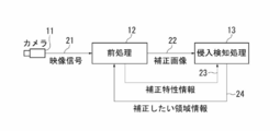
本例の侵入検知システムでは、監視領域を撮影するカメラ11から映像信号21を得て所定のフレーム間隔毎の入力画像を取得し、入力画像を前処理部12でコントラスト強調し、その結果として得られた補正画像22を侵入検知処理部13で解析することで、監視領域に対する侵入物の検知精度の向上を図る。また、前処理部12から侵入検知処理部13に対して補正特性情報23を出力し、侵入検知処理部13から前処理部12に対して補正したい領域情報24を出力することにより、侵入物の失報や誤報を抑制した侵入検知が可能な構成とする。
なお、以下では、検知対象の侵入物として人(侵入者)を例に説明するが、他の物体の侵入検知であっても構わない。 An embodiment of the present invention will be described with reference to the drawings.
FIG. 1 shows an example of the configuration of an intrusion detection system according to an embodiment of the present invention.
In the intrusion detection system of this example, the
In the following, a person (intruder) is described as an example of an intruder to be detected, but intrusion detection of other objects may be performed.
図2には、前処理部12と侵入検知処理部13を一体に備えた侵入検知装置(本発明に係る物体検知装置の一例)のハードウェア構成の例を示してある。なお、前処理部12と侵入検知処理部13の各々を、互いに通信可能な別体の装置に設ける構成としてもよい。 The configurations of the
FIG. 2 shows an example of a hardware configuration of an intrusion detection device (an example of the object detection device according to the present invention) that is integrally provided with the
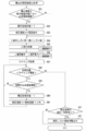
前処理部12は、まず、入力画像取込処理(ステップS11)で、カメラ11からの映像信号21を画像入力I/F部31でA/D変換して得られる入力画像を、画像メモリ32内の入力画像メモリ領域に格納する。
次に、初回判定処理(ステップS12)で、初回(1回目)の処理か否か(例えば、電源がOFFからONに切り替わった瞬間の処理か否か)を判定する。 The operation of the
First, the
Next, in the initial determination process (step S12), it is determined whether or not the process is the first (first) process (for example, whether or not the process is the moment when the power is switched from OFF to ON).
背景更新率要求コマンド出力処理(ステップS14)では、侵入検知処理部13に対して、背景更新率要求コマンドを出力する。
補正領域初期化処理(ステップS15)では、後述するコントラスト補正処理(ステップS21)の対象となる補正領域として、画面全体を設定する。なお、ここでいう画面は、入力画像に対応する。 In the corrected base image (whole) registration process (step S13), the input image stored in the input image memory area in the
In the background update rate request command output process (step S14), a background update rate request command is output to the intrusion
In the correction area initialization process (step S15), the entire screen is set as a correction area that is a target of a contrast correction process (step S21) described later. The screen here corresponds to the input image.
背景更新率登録済み判定処理(ステップS16)で侵入検知処理部13から応答がなかったと判定された場合には、出力画像作成(補正なし)処理(ステップS26)を実行する。
出力画像作成(補正なし)処理(ステップS26)では、画像メモリ32内の入力画像メモリ領域に格納されている入力画像を、画像メモリ32内の出力画像メモリ領域にコピーすることにより、出力画像を得る。出力画像作成(補正なし)処理(ステップS26)の後は、後述する映像出力処理(ステップS23)へ移行する。 Thereafter, whether or not there is a response from the intrusion
When it is determined that there is no response from the intrusion
In the output image creation (without correction) process (step S26), the input image stored in the input image memory area in the
背景更新率登録処理(ステップS17)では、侵入検知処理部13から応答された背景更新率を登録する。なお、背景更新率が登録済みの場合には、背景更新率登録処理(ステップS17)はスキップする。 On the other hand, if it is determined that there is a response from the intrusion
In the background update rate registration process (step S17), the background update rate returned from the intrusion
補正領域受信判定処理(ステップS18)で侵入検知処理部13から補正したい領域情報24を受信したと判定された場合には、補正ベース画像(補正領域のみ)登録処理(ステップS19)、補正領域登録処理(ステップS20)を実行する。 Thereafter, in the correction area reception determination process (step S18), it is determined whether or not the
If it is determined in the correction area reception determination process (step S18) that the
補正領域登録処理(ステップS20)では、後述するコントラスト補正処理(ステップS21)の対象となる補正領域として、補正したい領域情報24で示された補正領域を登録する。 In the correction base image (only correction area) registration process (step S19), the correction base image (entire) obtained in the correction base image (whole) registration process (step S13) is indicated by the
In the correction area registration process (step S20), the correction area indicated by the
その後、映像出力処理(ステップS23)で、画像メモリ32内の出力画像メモリ領域に格納されている出力画像(コントラスト補正画像又は入力画像)を、補正画像22として侵入検知処理部13に出力する。 In the output image creation process (step S22), the contrast corrected image obtained in the contrast correction process (step S21) is copied to the output image memory area in the
Thereafter, in the video output process (step S23), the output image (contrast correction image or input image) stored in the output image memory area in the
コマンド出力間隔判断処理(ステップS24)で前回のコマンド送信からの経過時間が規定時間(T秒)未満と判断された場合には、入力画像取込処理(ステップS11)に戻る。 Thereafter, an elapsed time from the previous command transmission is determined in a command output interval determination process (step S24).
If it is determined in the command output interval determination process (step S24) that the elapsed time from the previous command transmission is less than the specified time (T seconds), the process returns to the input image capture process (step S11).
補正特性情報出力処理(ステップS25)では、侵入検知処理部13に対して補正特性情報23を出力する。補正特性情報23には、後述するように、コントラストの補正(強調)に関する画像特性を示す情報が格納される。なお、1フレーム間での輝度レベルの変化の割合は少ないことや、コマンド送受信に負荷をかけないこと等を考慮すれば、補正特性情報23の出力は数秒間に1回で十分と考えられる。 On the other hand, if it is determined in the command output interval determination process (step S24) that the elapsed time from the previous command transmission is equal to or longer than the specified time (T seconds), after executing the correction characteristic information output process (step S25), The process returns to the input image capture process (step S11).
In the correction characteristic information output process (step S25), the correction
図4には、基本的なコントラスト強調の様子を示してある。
まず、図4(a)に例示するコントラスト強調前の入力画像に対して、輝度レベル(本例では、0~255の256階調)毎に出現頻度(該当する画素の数)を算出することにより、図4(b)に例示するヒストグラムを得る。
次に、このヒストグラムについて、輝度レベル毎に累積頻度を算出する。 Details of the contrast correction processing (step S21) will be described with reference to FIG.
FIG. 4 shows the basic contrast enhancement.
First, with respect to the input image before contrast enhancement illustrated in FIG. 4A, the appearance frequency (the number of corresponding pixels) is calculated for each luminance level (256 gradations of 0 to 255 in this example). Thus, the histogram illustrated in FIG. 4B is obtained.
Next, for this histogram, the cumulative frequency is calculated for each luminance level.
累積頻度(0)=輝度(0)の頻度
累積頻度(1)=輝度(0)の頻度+輝度(1)の頻度
・・・・
累積頻度(127)=輝度(0)の頻度~輝度(127)の頻度の合計
・・・・
累積頻度(255)=輝度(0)の頻度~輝度(255)の頻度の合計
輝度レベル毎の累積頻度をグラフ化したものが、図4(c)に例示する累積頻度グラフとなる。 The cumulative frequency for each luminance level is calculated as follows. Here, the numerical value in parentheses in each of the following expressions represents the luminance level.
Cumulative frequency (0) = Frequency of luminance (0) Cumulative frequency (1) = Frequency of luminance (0) + Frequency of luminance (1)
Cumulative frequency (127) = frequency of luminance (0) to total frequency of luminance (127)
Cumulative frequency (255) = frequency of luminance (0) to total frequency of luminance (255) A graph of the cumulative frequency for each luminance level is the cumulative frequency graph illustrated in FIG. 4C.
例えば、図4(a)のように霧等によってコントラストが低下している場合には、図4(b)や(c)のように輝度レベルが高い部分(輝度レベル=255に近い部分)に偏った頻度分布となる。また、暗闇等によってコントラストが低下している場合には、輝度レベルが低い部分(輝度レベル=0に近い部分)に偏った頻度分布となる。 Next, the minimum value and the maximum value of the cumulative frequency are calculated from the cumulative frequency for each luminance level. The minimum value is the value of the rising portion (cumulative frequency) greater than the cumulative frequency (0), and the maximum value is the value of the first portion (cumulative frequency) where cumulative frequency = image size (width × height). It is. The deviation of the luminance level in the input image can be determined from the minimum value and the maximum value of the cumulative frequency.
For example, when the contrast is lowered due to fog or the like as shown in FIG. 4A, a portion with a high luminance level (a portion close to the luminance level = 255) as shown in FIGS. 4B and 4C is used. It becomes a biased frequency distribution. Further, when the contrast is lowered due to darkness or the like, the frequency distribution is biased toward a portion with a low luminance level (a portion close to luminance level = 0).
また、上記の(式1)によりコントラスト強調を行う対象の範囲(i,jの範囲)を画面全体とすれば、全体的なコントラスト強調を行うことが可能となり、対象の範囲を画面の一部とすれば、局所的なコントラスト強調を行うことが可能となる。 When contrast enhancement is performed according to the above (Equation 1), a histogram illustrated in FIG. 4D is obtained. That is, a frequency distribution that is biased near a certain luminance level can be leveled into a frequency distribution that is distributed over the entire range of luminance levels. As a result, as illustrated in FIG. 4E, it is possible to enhance the contrast (enlarge the luminance difference) for a building or an object (person) with a low contrast (small luminance difference).
Further, if the range of the object (i, j range) for which contrast enhancement is performed by the above (Equation 1) is the entire screen, it is possible to perform overall contrast enhancement, and the range of the object is a part of the screen. Then, local contrast enhancement can be performed.
コントラスト補正画像=補正ベース画像×(1-背景更新率)
+コントラスト強調後画像×背景更新率 ・・・(式2)
すなわち、背景更新率が大きいほどコントラスト強調後画像の寄与率を高めたコントラスト補正画像を作成する。 Here, at the moment when contrast enhancement is turned from OFF (stop) to ON (start) or from ON (start) to OFF (stop), the luminance is not only in the part where the intruder exists but also in the background part such as a building. The level changes greatly. Therefore, in this example, instead of simply copying the contrast-enhanced image to obtain the contrast-corrected image (corrected image 22), the weighted average of the corrected base image and the contrast-enhanced image is calculated by the following (Equation 2). Thus, a contrast-corrected image (corrected image 22) is created and used for intrusion detection by the intrusion
Contrast correction image = correction base image × (1−background update rate)
+ Contrast-enhanced image × background update rate (Equation 2)
That is, a contrast-corrected image in which the contribution rate of the post-contrast-enhanced image is increased as the background update rate increases.
侵入検知処理部13は、まず、背景画像作成処理(ステップS31)で、侵入検知に用いる背景画像の作成を行う。背景画像は、時間的に異なる複数の入力画像(補正画像22)の加重平均を取ることにより、検出の目的となる物体(侵入物)の存在しない状態の画像を作成する。背景画像の作成は、例えば、特開2009-282975号公報に開示された技術を用いることで作成することができる。 The operation of the intrusion
The intrusion
その後、背景更新率要求コマンド受信判定処理(ステップS33)で、前処理部12から背景更新率要求コマンドを受信したか否かを判定する。
背景更新率要求コマンド受信判定処理(ステップS33)で背景更新率要求コマンドを受信したと判定された場合には、背景更新率応答コマンド出力処理(ステップS34)を実行する。一方、背景更新率要求コマンド受信判定処理(ステップS33)で背景更新率要求コマンドを受信しなかったと判定された場合には、背景更新率応答コマンド出力処理(ステップS34)はスキップする。 After completion of the background image creation by the background image creation processing (step S31), a new input image (corrected image 22) is captured by the input image capture processing (step S32).
Thereafter, in a background update rate request command reception determination process (step S33), it is determined whether or not a background update rate request command has been received from the preprocessing
If it is determined in the background update rate request command reception determination process (step S33) that the background update rate request command has been received, a background update rate response command output process (step S34) is executed. On the other hand, if it is determined in the background update rate request command reception determination process (step S33) that the background update rate request command has not been received, the background update rate response command output process (step S34) is skipped.
補正特性情報受信判定処理(ステップS35)で補正特性情報23を受信したと判定された場合には、二値化しきい値登録処理(ステップS36)を実行する。一方、補正特性情報受信判定処理(ステップS35)で補正特性情報23を受信しなかったと判定された場合には、二値化しきい値登録処理(ステップS36)はスキップする。 Further, in the correction characteristic information reception determination process (step S35), it is determined whether or not the correction
If it is determined in the correction characteristic information reception determination process (step S35) that the correction
差分処理(ステップS37)では、背景画像作成処理(ステップS31)で得られた背景画像と、入力画像取込み処理(ステップS32)で得られた入力画像(補正画像22)との差分を算出し、差分画像(入力画像-背景画像)を作成する。入力画像(補正画像22)と背景画像との差分は、符号付きで算出してもよく、絶対値として算出してもよい。なお、後述の背景画像更新処理(ステップS44)が実施された場合には、背景画像更新処理(ステップS44)による更新後の背景画像を用いて差分画像が作成される。 Thereafter, a difference process (step S37), a binarization process (step S38), a noise removal process (step S39), and a labeling process (step S40) are executed.
In the difference process (step S37), the difference between the background image obtained in the background image creation process (step S31) and the input image (corrected image 22) obtained in the input image capture process (step S32) is calculated. A difference image (input image-background image) is created. The difference between the input image (corrected image 22) and the background image may be calculated with a sign or may be calculated as an absolute value. When background image update processing (step S44) described later is performed, a difference image is created using the background image updated by the background image update processing (step S44).
ノイズ除去処理(ステップS39)では、二値化処理(ステップS38)で作成された二値画像に含まれるノイズを除去し、ノイズ除去画像を作成する。本例では、二値画像に含まれる画素のかたまりのうち、所定の画素数未満のものをノイズとして除去する。
ラベリング処理(ステップS40)では、ノイズ除去処理(ステップS39)で作成されたノイズ除去画像に残っている画素のかたまりを物体と見做して物体(かたまり)毎にラベル付け(識別情報を付与)し、各物体の幅、高さ、面積を算出する。 In the binarization process (step S38), the difference image obtained in the difference process (step S37) is binarized by the binarization threshold value registered in the binarization threshold value registration process (step S36). Create a binary image. That is, a binary image is created by setting the luminance value of pixels below the binarization threshold to 0 and the luminance value of pixels above the binarization threshold to 255.
In the noise removal process (step S39), noise included in the binary image created in the binarization process (step S38) is removed, and a noise-removed image is created. In this example, a pixel group less than a predetermined number of pixels included in the binary image is removed as noise.
In the labeling process (step S40), a pixel block remaining in the noise-removed image created in the noise removal process (step S39) is regarded as an object and labeled for each object (chunk) (identification information is given). Then, the width, height, and area of each object are calculated.
次に、侵入者判定処理(ステップS42)で、物体判定処理(ステップS41)で判別された物体が人(侵入者)か否かを判定し、侵入者と判定された場合には、警報処理(ステップS43)で、パトライト(登録商標)を点灯する、ブザーを鳴らす、サーバに通知する等、外部機器により警報出力を行う。 Thereafter, in the object determination process (step S41), the type of the object is determined for each object obtained in the labeling process (step S40) based on the size of the object, the staying time, the moving distance, and the like. The size of the object can be specified based on, for example, the width, height, and area of the object obtained by the labeling process (step S40). Further, the staying time of the object can be specified based on the number of input images (number of frames) in which the object is detected among a plurality of input images that are temporally different. Also, the moving distance of the object can be specified based on, for example, position information of the object in a plurality of input images that are temporally different.
Next, in the intruder determination process (step S42), it is determined whether or not the object determined in the object determination process (step S41) is a person (intruder). In step S43, an alarm is output from an external device such as turning on Patlite (registered trademark), sounding a buzzer, or notifying the server.
背景画像更新処理(ステップS44)では、背景画像の更新を行う。背景画像の更新は、時々刻々と変化する映像状態に追従するため、入力画像(補正画像22)を取り込むたびに実行される。
映像表示処理(ステップS45)では、入力画像(補正画像22)を画像出力I/F37によりD/A変換し、監視員が監視するモニタ等に出力して表示させる。また、侵入者ありの場合には「侵入者検知」の文字や検知箇所を示すマーカー等を入力画像(補正画像22)に重畳したもの(侵入者情報付き画像)をモニタへ出力する。 Thereafter, background image update processing (step S44), video display processing (step S45), and correction necessary area calculation processing (step S46) are executed.
In the background image update process (step S44), the background image is updated. The background image is updated every time an input image (corrected image 22) is captured in order to follow a video state that changes every moment.
In the video display process (step S45), the input image (corrected image 22) is D / A converted by the image output I /
まず、補正必要性判定処理(ステップS51)で、コントラストの補正(コントラスト強調)を画面全体に施す必要性の有無を判定する。具体的には、補正特性情報23で示された最小輝度と最大輝度の差分である輝度差を算出し、輝度差が小さく(すなわち、輝度差が所定の基準差分値未満であり)、且つ、補正領域として画面全体が登録されていない場合に、画面全体のコントラスト補正が必要と判定する。 Details of the correction required area calculation process (step S46) will be described with reference to the process flow illustrated in FIG.
First, it is determined whether or not it is necessary to perform contrast correction (contrast enhancement) on the entire screen in a correction necessity determination process (step S51). Specifically, a luminance difference that is a difference between the minimum luminance and the maximum luminance indicated by the correction
全体補正領域登録処理(ステップS53)では、n番目の補正領域として画面全体を登録する。
なお、図6の処理フローには示していないが、補正領域として画面全体が既に登録されている状態において、最小輝度と最大輝度の輝度差が小さくなかった場合(すなわち、輝度差が所定の基準差分値以上の場合)には、補正領域から画面全体を削除し、補正領域数をデクリメント(-1)する。 In the correction area number increment process (step S52), the correction area number n is incremented (+1). The correction area number n is set to 0 as an initial value.
In the entire correction area registration process (step S53), the entire screen is registered as the nth correction area.
Although not shown in the processing flow of FIG. 6, in a state where the entire screen is already registered as the correction area, when the luminance difference between the minimum luminance and the maximum luminance is not small (that is, the luminance difference is a predetermined reference). If the difference value is greater than or equal to the difference value, the entire screen is deleted from the correction area, and the number of correction areas is decremented (−1).
二値化しきい値登録処理(ステップS54)では、補正必要領域を算出するのに必要な最小しきい値を予め設定しておき、この最小しきい値を二値化しきい値として登録する。最小しきい値としては、二値化しきい値登録処理(ステップS36)で登録した二値化しきい値より低い(小さい)値が用いられる。
二値化処理(ステップS55)では、差分処理(ステップS37)で得られた差分画像を、二値化しきい値登録処理(ステップS55)で登録された二値化しきい値により二値化して、二値画像を作成する。すなわち、二値化しきい値未満の画素の輝度値を0、二値化しきい値以上の画素の輝度値を255として、二値画像を作成する。 Next, binarization threshold value registration processing (step S54), binarization processing (step S55), correction area extraction processing (step S56), and labeling processing (step S57) are executed.
In the binarization threshold value registration process (step S54), a minimum threshold value necessary for calculating the correction required region is set in advance, and this minimum threshold value is registered as the binarization threshold value. As the minimum threshold value, a value lower (smaller) than the binarization threshold value registered in the binarization threshold value registration process (step S36) is used.
In the binarization process (step S55), the difference image obtained in the difference process (step S37) is binarized by the binarization threshold value registered in the binarization threshold value registration process (step S55). Create a binary image. That is, a binary image is created by setting the luminance value of pixels below the binarization threshold to 0 and the luminance value of pixels above the binarization threshold to 255.
ラベリング処理(ステップS57)では、補正領域抽出処理(ステップS56)で得られた二値画像Cに対してラベリング処理を行い、二値画像Cに含まれる画素のかたまりを物体と見做して物体(かたまり)毎にラベル付け(識別情報を付与)し、その物体の幅、高さ、面積を算出する。 In the correction area extraction process (step S56), the binary image created in the binarization process (step S38) is defined as a binary image A, and the binary image created in the binarization process (step S56) is binarized. As the image B, a difference between the binary image A and the binary image B is calculated, and a binary image C that is a difference image between the binary image A and the binary image B is created.
In the labeling process (step S57), a labeling process is performed on the binary image C obtained by the correction area extraction process (step S56), and a group of pixels included in the binary image C is regarded as an object. Label (add identification information) for each (group) and calculate the width, height, and area of the object.
補正領域判定処理(ステップS59)では、ラベリング処理(ステップS57)でラベリングされた物体毎に、コントラストの補正(コントラスト)を施す必要性の有無を判定する。具体的には、ラベリング処理(ステップS57)で得られた面積が大きく(すなわち、面積が所定の基準面積値以上であり)、且つ、補正領域として登録されていない場合に、その物体の画像部分について局所的なコントラスト補正が必要と判定する。 If it is determined in the processing number determination process (step S58) that the number of post-labeling processes is smaller than the number of labeling (there is an unprocessed one), a correction area determination process (step S59) is executed.
In the correction area determination process (step S59), it is determined whether or not it is necessary to perform contrast correction (contrast) for each object labeled in the labeling process (step S57). Specifically, when the area obtained by the labeling process (step S57) is large (that is, the area is equal to or larger than a predetermined reference area value) and is not registered as a correction area, the image portion of the object Is determined to require local contrast correction.
補正領域数インクリメント処理(ステップS60)では、補正領域数nをインクリメント(+1)する。
局所補正領域登録処理(ステップS61)では、n番目の補正領域(局所補正領域)として、ラベリング処理(ステップS57)で得られた幅、高さを±規定値(α%)分だけ広げた領域(拡張領域)を登録する。
なお、図6の処理フローには示していないが、局所補正領域登録処理(ステップS61)で登録された補正領域に関し、ラベリング処理(ステップS57)で得られた物体の画素数が小さい(すなわち、画素数が所定の基準画素数未満)の状態が規定時間(数秒)継続した場合には、その物体に対応する領域(拡張領域)を補正領域から削除し、補正領域数をデクリメント(-1)する。 If it is determined in the correction area determination process (step S59) that local contrast correction is necessary, a correction area increment process (step S60) and a local correction area registration process (step S61) are further executed.
In the correction area number increment process (step S60), the correction area number n is incremented (+1).
In the local correction area registration process (step S61), as the nth correction area (local correction area), an area obtained by expanding the width and height obtained in the labeling process (step S57) by ± specified values (α%) Register (extended area).
Although not shown in the processing flow of FIG. 6, regarding the correction area registered in the local correction area registration process (step S61), the number of pixels of the object obtained in the labeling process (step S57) is small (that is, When the state where the number of pixels is less than the predetermined reference number of pixels continues for a specified time (several seconds), the area corresponding to the object (extended area) is deleted from the correction area, and the number of correction areas is decremented (−1) To do.
補正領域追加/削除判定処理(ステップS62)では、前処理フレーム(前回処理した入力画像)の補正領域数と、現処理フレーム(現在処理中の入力画像)の補正領域数とを比較し、補正領域数の変化の有無を判定する。 When it is determined in the processing number determination process (step S58) that the number of post-labeling processes is larger than the number of labeling, that is, when the correction area determination process (step S59) is executed for all the labeled objects, Correction area addition / deletion determination processing (step S62) is executed.
In the correction area addition / deletion determination process (step S62), the number of correction areas of the preprocessed frame (previous input image) is compared with the number of correction areas of the current process frame (currently processed input image) to perform correction. Whether there is a change in the number of areas is determined.
補正領域情報出力処理(ステップS64)では、前処理部12に対し、補正したい領域情報24として、補正領域として登録されている領域の情報を送信する。
以上の処理により、侵入検知に適したコントラスト強調が可能となる。 If it is determined in the correction area addition / deletion determination process (step S62) that the number of correction areas has changed, a correction area information output process (step S64) is executed. On the other hand, if it is determined in the correction area addition / deletion determination process (step S62) that there is no change in the number of correction areas, the correction area information output process (step S64) is skipped.
In the correction area information output process (step S64), information on the area registered as the correction area is transmitted as the
With the above processing, contrast enhancement suitable for intrusion detection can be performed.
また、本発明の適用分野としては、必ずしも以上に示したものに限られず、本発明は、種々な分野に適用することが可能なものである。
また、本発明に係るシステムや装置などにおいて行われる各種の処理としては、例えばプロセッサやメモリ等を備えたハードウェア資源においてプロセッサがROM(Read Only Memory)に格納された制御プログラムを実行することにより制御される構成が用いられてもよく、また、例えば当該処理を実行するための各機能手段が独立したハードウェア回路として構成されてもよい。
また、本発明は上記の制御プログラムを格納したフロッピー(登録商標)ディスクやCD(Compact Disc)-ROM等のコンピュータにより読み取り可能な記録媒体や当該プログラム(自体)として把握することもでき、当該制御プログラムを当該記録媒体からコンピュータに入力してプロセッサに実行させることにより、本発明に係る処理を遂行させることができる。 Here, the configuration of the system and apparatus according to the present invention is not necessarily limited to the configuration described above, and various configurations may be used. The present invention can also be provided as, for example, a method or method for executing the processing according to the present invention, a program for realizing such a method or method, or a recording medium for recording the program. It is also possible to provide various systems and devices.
The application field of the present invention is not necessarily limited to the above-described fields, and the present invention can be applied to various fields.
In addition, as various processes performed in the system and apparatus according to the present invention, for example, the processor executes a control program stored in a ROM (Read Only Memory) in hardware resources including a processor and a memory. A controlled configuration may be used, and for example, each functional unit for executing the processing may be configured as an independent hardware circuit.
Further, the present invention can be grasped as a computer-readable recording medium such as a floppy (registered trademark) disk or a CD (Compact Disc) -ROM storing the control program, or the program (itself). The processing according to the present invention can be performed by inputting the program from the recording medium to the computer and causing the processor to execute the program.
Claims (9)
- 監視領域を撮像するカメラからの入力画像に基づいて、監視領域内に現れた物体を検知する物体検知装置において、
入力画像に対してコントラストを強調する補正を行う前処理手段と、
前記前処理手段による補正後の入力画像と、当該補正に関する画像特性を含む補正特性情報とを用いて、監視領域内に現れた物体の検知を行う物体検知手段と、を備えたことを特徴とする物体検知装置。 In an object detection device that detects an object that appears in a monitoring area based on an input image from a camera that images the monitoring area,
Preprocessing means for performing correction for enhancing the contrast on the input image;
And an object detection means for detecting an object appearing in the monitoring area using the input image corrected by the preprocessing means and correction characteristic information including image characteristics related to the correction. Object detection device. - 監視領域を撮像するカメラからの入力画像に基づいて、監視領域内に現れた物体を検知する物体検知装置により実施される方法において、
入力画像に対してコントラストを強調する補正を行う前処理ステップと、
前記前処理手段による補正後の入力画像と、当該補正に関する画像特性を含む補正特性情報とを用いて、監視領域内に現れた物体の検知を行う物体検知ステップと、を有することを特徴とする物体検知方法。 In a method implemented by an object detection device that detects an object that appears in a monitoring area based on an input image from a camera that images the monitoring area,
A preprocessing step for correcting the input image to enhance contrast;
An object detection step of detecting an object appearing in the monitoring area using the input image corrected by the preprocessing means and correction characteristic information including image characteristics related to the correction. Object detection method. - 監視領域を撮像するカメラからの入力画像に基づいて、監視領域内に現れた物体を検知する物体検知装置のコンピュータに、
入力画像に対してコントラストを強調する補正を行う前処理機能と、
前記前処理機能による補正後の入力画像と、当該補正に関する画像特性を含む補正特性情報とを用いて、監視領域内に現れた物体の検知を行う物体検知機能と、を実現させるためのプログラム。 Based on the input image from the camera that images the monitoring area, to the computer of the object detection device that detects the object that appears in the monitoring area,
A pre-processing function for performing correction to enhance the contrast of the input image;
A program for realizing an object detection function for detecting an object appearing in a monitoring area using an input image after correction by the preprocessing function and correction characteristic information including image characteristics related to the correction. - 請求項1に記載の物体検知装置において、
前記前処理手段は、前記物体検知手段により検知された物体の位置に基づいて、入力画像に対して補正する、ことを特徴とする物体検知装置。 The object detection apparatus according to claim 1,
The pre-processing means corrects the input image based on the position of the object detected by the object detection means. - 請求項2に記載の物体検知方法において、
前記前処理ステップは、前記物体検知ステップにより検知された物体の位置に基づいて、入力画像に対して補正する、ことを特徴とする物体検知方法。 The object detection method according to claim 2,
The pre-processing step corrects the input image based on the position of the object detected by the object detection step. - 請求項3に記載のプログラムにおいて、
前記前処理機能は、前記物体検知手段により検知された物体の位置に基づいて、入力画像に対して補正する、ことを特徴とするプログラム。 In the program according to claim 3,
The program according to claim 1, wherein the preprocessing function corrects an input image based on a position of an object detected by the object detection means. - 請求項1に記載の物体検知装置において、
前記物体検知手段は、入力画像を取り込む毎に、物体の検知における入力画像との比較対象となる背景画像を更新しており、
前記前処理手段は、前記物体検知手段における背景画像の更新率に応じて入力画像の補正量を調整する、ことを特徴とする物体検知装置。 The object detection apparatus according to claim 1,
The object detection unit updates the background image to be compared with the input image in the detection of the object every time the input image is captured,
The object detection apparatus, wherein the preprocessing means adjusts a correction amount of an input image in accordance with a background image update rate in the object detection means. - 請求項2に記載の物体検知方法において、
前記物体検知ステップは、入力画像を取り込む毎に、物体の検知における入力画像との比較対象となる背景画像を更新しており、
前記前処理ステップは、前記物体検知ステップにおける背景画像の更新率に応じて入力画像の補正量を調整する、ことを特徴とする物体検知装置。 The object detection method according to claim 2,
The object detection step updates the background image to be compared with the input image in the detection of the object every time the input image is captured,
The pre-processing step adjusts the correction amount of the input image according to the update rate of the background image in the object detection step. - 請求項3に記載のプログラムにおいて、
前記物体検知機能は、入力画像を取り込む毎に、物体の検知における入力画像との比較対象となる背景画像を更新しており、
前記前処理機能は、前記物体検知機能における背景画像の更新率に応じて入力画像の補正量を調整する、ことを特徴とするプログラム。 In the program according to claim 3,
The object detection function updates the background image to be compared with the input image in object detection every time the input image is captured,
The program according to claim 1, wherein the preprocessing function adjusts a correction amount of an input image in accordance with a background image update rate in the object detection function.
Priority Applications (2)
| Application Number | Priority Date | Filing Date | Title |
|---|---|---|---|
| US14/378,388 US9443150B2 (en) | 2012-03-07 | 2012-11-30 | Device and method for detecting objects from a video signal |
| GB1415683.0A GB2514301B (en) | 2012-03-07 | 2012-11-30 | Object detection device, object detection method and program |
Applications Claiming Priority (2)
| Application Number | Priority Date | Filing Date | Title |
|---|---|---|---|
| JP2012-050396 | 2012-03-07 | ||
| JP2012050396A JP5950628B2 (en) | 2012-03-07 | 2012-03-07 | Object detection apparatus, object detection method, and program |
Publications (1)
| Publication Number | Publication Date |
|---|---|
| WO2013132711A1 true WO2013132711A1 (en) | 2013-09-12 |
Family
ID=49116210
Family Applications (1)
| Application Number | Title | Priority Date | Filing Date |
|---|---|---|---|
| PCT/JP2012/081144 WO2013132711A1 (en) | 2012-03-07 | 2012-11-30 | Object detection device, object detection method and program |
Country Status (4)
| Country | Link |
|---|---|
| US (1) | US9443150B2 (en) |
| JP (1) | JP5950628B2 (en) |
| GB (1) | GB2514301B (en) |
| WO (1) | WO2013132711A1 (en) |
Families Citing this family (5)
| Publication number | Priority date | Publication date | Assignee | Title |
|---|---|---|---|---|
| US20160371847A1 (en) * | 2014-07-24 | 2016-12-22 | Bonanza.com, LLC | Background profiles |
| US20170034459A1 (en) * | 2015-07-30 | 2017-02-02 | Motorola Mobility Llc | Electronic Device with Image Correction System and Methods Therefor |
| SG11201801781RA (en) * | 2015-09-18 | 2018-04-27 | Hitachi Int Electric Inc | Image-processing device |
| US11516385B2 (en) * | 2020-12-09 | 2022-11-29 | Microsoft Technology Licensing, Llc | Dynamic quality proxy plural camera image blending |
| CN112530216B (en) * | 2020-12-16 | 2022-06-21 | 北京新大陆时代教育科技有限公司 | Immersive virtual-real interaction practical training system and method |
Citations (4)
| Publication number | Priority date | Publication date | Assignee | Title |
|---|---|---|---|---|
| JPH04213195A (en) * | 1990-12-06 | 1992-08-04 | Japan Radio Co Ltd | Intruder monitoring system |
| JPH08171689A (en) * | 1994-12-19 | 1996-07-02 | Kansai Electric Power Co Inc:The | Changed area detector |
| JP2001197483A (en) * | 2000-01-12 | 2001-07-19 | Yokogawa Electric Corp | Equipment monitor system using image processing means |
| JP2005115932A (en) * | 2003-09-16 | 2005-04-28 | Matsushita Electric Works Ltd | Human body sensing device using image |
Family Cites Families (12)
| Publication number | Priority date | Publication date | Assignee | Title |
|---|---|---|---|---|
| KR100763239B1 (en) * | 2006-06-27 | 2007-10-04 | 삼성전자주식회사 | Image processing apparatus and method for enhancing visibility of image on display |
| US8432448B2 (en) * | 2006-08-10 | 2013-04-30 | Northrop Grumman Systems Corporation | Stereo camera intrusion detection system |
| US8437566B2 (en) * | 2007-04-27 | 2013-05-07 | Microsemi Corporation | Software methodology for autonomous concealed object detection and threat assessment |
| JP5354767B2 (en) * | 2007-10-17 | 2013-11-27 | 株式会社日立国際電気 | Object detection device |
| JP5202551B2 (en) * | 2009-01-23 | 2013-06-05 | 株式会社日立国際電気 | Parameter setting method and monitoring apparatus using the method |
| JP5260431B2 (en) * | 2009-07-22 | 2013-08-14 | セコム株式会社 | Object detection device |
| JP5023203B2 (en) * | 2010-08-24 | 2012-09-12 | 株式会社東芝 | Image correction apparatus and correction parameter creation apparatus |
| JP5719141B2 (en) * | 2010-10-28 | 2015-05-13 | キヤノン株式会社 | Information processing apparatus, processing method thereof, and program |
| US20130170760A1 (en) * | 2011-12-29 | 2013-07-04 | Pelco, Inc. | Method and System for Video Composition |
| US9530221B2 (en) * | 2012-01-06 | 2016-12-27 | Pelco, Inc. | Context aware moving object detection |
| JP5948983B2 (en) * | 2012-03-09 | 2016-07-06 | オムロン株式会社 | Image processing apparatus, image processing method, and image processing program |
| US10373470B2 (en) * | 2013-04-29 | 2019-08-06 | Intelliview Technologies, Inc. | Object detection |
-
2012
- 2012-03-07 JP JP2012050396A patent/JP5950628B2/en active Active
- 2012-11-30 WO PCT/JP2012/081144 patent/WO2013132711A1/en active Application Filing
- 2012-11-30 GB GB1415683.0A patent/GB2514301B/en active Active
- 2012-11-30 US US14/378,388 patent/US9443150B2/en not_active Expired - Fee Related
Patent Citations (4)
| Publication number | Priority date | Publication date | Assignee | Title |
|---|---|---|---|---|
| JPH04213195A (en) * | 1990-12-06 | 1992-08-04 | Japan Radio Co Ltd | Intruder monitoring system |
| JPH08171689A (en) * | 1994-12-19 | 1996-07-02 | Kansai Electric Power Co Inc:The | Changed area detector |
| JP2001197483A (en) * | 2000-01-12 | 2001-07-19 | Yokogawa Electric Corp | Equipment monitor system using image processing means |
| JP2005115932A (en) * | 2003-09-16 | 2005-04-28 | Matsushita Electric Works Ltd | Human body sensing device using image |
Also Published As
| Publication number | Publication date |
|---|---|
| JP5950628B2 (en) | 2016-07-13 |
| GB201415683D0 (en) | 2014-10-22 |
| JP2013186635A (en) | 2013-09-19 |
| GB2514301B (en) | 2016-06-22 |
| US20150043775A1 (en) | 2015-02-12 |
| US9443150B2 (en) | 2016-09-13 |
| GB2514301A (en) | 2014-11-19 |
Similar Documents
| Publication | Publication Date | Title |
|---|---|---|
| KR101375583B1 (en) | Object Density Estimation in Video | |
| US6754367B1 (en) | Method and apparatus for automatically detecting intrusion object into view of image pickup device | |
| US7778445B2 (en) | Method and system for the detection of removed objects in video images | |
| JP4811653B2 (en) | Object detection device | |
| JP4203736B2 (en) | Image motion detection apparatus and computer program | |
| US20170337431A1 (en) | Image processing apparatus and method and monitoring system | |
| JP5388829B2 (en) | Intruder detection device | |
| JP5950628B2 (en) | Object detection apparatus, object detection method, and program | |
| JP2008241707A (en) | Automatic monitoring system | |
| KR102127276B1 (en) | The System and Method for Panoramic Video Surveillance with Multiple High-Resolution Video Cameras | |
| KR101758685B1 (en) | Method, system for detecting camera tampering | |
| US7982774B2 (en) | Image processing apparatus and image processing method | |
| JP2000184359A (en) | Monitoring device and system therefor | |
| JP2001160146A (en) | Method and device for recognizing image | |
| JP5710230B2 (en) | Monitoring system and monitoring method | |
| JP2011258214A (en) | Object detector | |
| JP2017005485A (en) | Picture monitoring device and picture monitoring method | |
| JP3736836B2 (en) | Object detection method, object detection apparatus, and program | |
| JP2002150440A (en) | Detector for object of monitoring | |
| JP2002218443A (en) | Intruding object detection method and intruding object monitoring apparatus for automatically determining threshold for intruding object detection | |
| JP6124739B2 (en) | Image sensor | |
| JP4619082B2 (en) | Image determination device | |
| JP2001169270A (en) | Image supervisory device and image supervisory method | |
| JP2004128648A (en) | Method for tracing intruding object | |
| JP2003319385A (en) | Method and apparatus for detecting object |
Legal Events
| Date | Code | Title | Description |
|---|---|---|---|
| 121 | Ep: the epo has been informed by wipo that ep was designated in this application |
Ref document number: 12870696 Country of ref document: EP Kind code of ref document: A1 |
|
| NENP | Non-entry into the national phase |
Ref country code: DE |
|
| WWE | Wipo information: entry into national phase |
Ref document number: 14378388 Country of ref document: US |
|
| ENP | Entry into the national phase |
Ref document number: 1415683 Country of ref document: GB Kind code of ref document: A Free format text: PCT FILING DATE = 20121130 |
|
| WWE | Wipo information: entry into national phase |
Ref document number: 1415683.0 Country of ref document: GB |
|
| 122 | Ep: pct application non-entry in european phase |
Ref document number: 12870696 Country of ref document: EP Kind code of ref document: A1 |