WO2013128837A1 - 車両用駆動制御装置、車両用駆動制御方法 - Google Patents
車両用駆動制御装置、車両用駆動制御方法 Download PDFInfo
- Publication number
- WO2013128837A1 WO2013128837A1 PCT/JP2013/000877 JP2013000877W WO2013128837A1 WO 2013128837 A1 WO2013128837 A1 WO 2013128837A1 JP 2013000877 W JP2013000877 W JP 2013000877W WO 2013128837 A1 WO2013128837 A1 WO 2013128837A1
- Authority
- WO
- WIPO (PCT)
- Prior art keywords
- power
- distribution ratio
- engine
- power distribution
- torque
- Prior art date
- Legal status (The legal status is an assumption and is not a legal conclusion. Google has not performed a legal analysis and makes no representation as to the accuracy of the status listed.)
- Ceased
Links
Images


Classifications
-
- B—PERFORMING OPERATIONS; TRANSPORTING
- B60—VEHICLES IN GENERAL
- B60K—ARRANGEMENT OR MOUNTING OF PROPULSION UNITS OR OF TRANSMISSIONS IN VEHICLES; ARRANGEMENT OR MOUNTING OF PLURAL DIVERSE PRIME-MOVERS IN VEHICLES; AUXILIARY DRIVES FOR VEHICLES; INSTRUMENTATION OR DASHBOARDS FOR VEHICLES; ARRANGEMENTS IN CONNECTION WITH COOLING, AIR INTAKE, GAS EXHAUST OR FUEL SUPPLY OF PROPULSION UNITS IN VEHICLES
- B60K6/00—Arrangement or mounting of plural diverse prime-movers for mutual or common propulsion, e.g. hybrid propulsion systems comprising electric motors and internal combustion engines
- B60K6/20—Arrangement or mounting of plural diverse prime-movers for mutual or common propulsion, e.g. hybrid propulsion systems comprising electric motors and internal combustion engines the prime-movers consisting of electric motors and internal combustion engines, e.g. HEVs
- B60K6/22—Arrangement or mounting of plural diverse prime-movers for mutual or common propulsion, e.g. hybrid propulsion systems comprising electric motors and internal combustion engines the prime-movers consisting of electric motors and internal combustion engines, e.g. HEVs characterised by apparatus, components or means specially adapted for HEVs
- B60K6/26—Arrangement or mounting of plural diverse prime-movers for mutual or common propulsion, e.g. hybrid propulsion systems comprising electric motors and internal combustion engines the prime-movers consisting of electric motors and internal combustion engines, e.g. HEVs characterised by apparatus, components or means specially adapted for HEVs characterised by the motors or the generators
-
- B—PERFORMING OPERATIONS; TRANSPORTING
- B60—VEHICLES IN GENERAL
- B60K—ARRANGEMENT OR MOUNTING OF PROPULSION UNITS OR OF TRANSMISSIONS IN VEHICLES; ARRANGEMENT OR MOUNTING OF PLURAL DIVERSE PRIME-MOVERS IN VEHICLES; AUXILIARY DRIVES FOR VEHICLES; INSTRUMENTATION OR DASHBOARDS FOR VEHICLES; ARRANGEMENTS IN CONNECTION WITH COOLING, AIR INTAKE, GAS EXHAUST OR FUEL SUPPLY OF PROPULSION UNITS IN VEHICLES
- B60K6/00—Arrangement or mounting of plural diverse prime-movers for mutual or common propulsion, e.g. hybrid propulsion systems comprising electric motors and internal combustion engines
- B60K6/20—Arrangement or mounting of plural diverse prime-movers for mutual or common propulsion, e.g. hybrid propulsion systems comprising electric motors and internal combustion engines the prime-movers consisting of electric motors and internal combustion engines, e.g. HEVs
- B60K6/42—Arrangement or mounting of plural diverse prime-movers for mutual or common propulsion, e.g. hybrid propulsion systems comprising electric motors and internal combustion engines the prime-movers consisting of electric motors and internal combustion engines, e.g. HEVs characterised by the architecture of the hybrid electric vehicle
- B60K6/44—Series-parallel type
- B60K6/448—Electrical distribution type
-
- B—PERFORMING OPERATIONS; TRANSPORTING
- B60—VEHICLES IN GENERAL
- B60K—ARRANGEMENT OR MOUNTING OF PROPULSION UNITS OR OF TRANSMISSIONS IN VEHICLES; ARRANGEMENT OR MOUNTING OF PLURAL DIVERSE PRIME-MOVERS IN VEHICLES; AUXILIARY DRIVES FOR VEHICLES; INSTRUMENTATION OR DASHBOARDS FOR VEHICLES; ARRANGEMENTS IN CONNECTION WITH COOLING, AIR INTAKE, GAS EXHAUST OR FUEL SUPPLY OF PROPULSION UNITS IN VEHICLES
- B60K6/00—Arrangement or mounting of plural diverse prime-movers for mutual or common propulsion, e.g. hybrid propulsion systems comprising electric motors and internal combustion engines
- B60K6/20—Arrangement or mounting of plural diverse prime-movers for mutual or common propulsion, e.g. hybrid propulsion systems comprising electric motors and internal combustion engines the prime-movers consisting of electric motors and internal combustion engines, e.g. HEVs
- B60K6/50—Architecture of the driveline characterised by arrangement or kind of transmission units
- B60K6/52—Driving a plurality of drive axles, e.g. four-wheel drive
-
- B—PERFORMING OPERATIONS; TRANSPORTING
- B60—VEHICLES IN GENERAL
- B60L—PROPULSION OF ELECTRICALLY-PROPELLED VEHICLES; SUPPLYING ELECTRIC POWER FOR AUXILIARY EQUIPMENT OF ELECTRICALLY-PROPELLED VEHICLES; ELECTRODYNAMIC BRAKE SYSTEMS FOR VEHICLES IN GENERAL; MAGNETIC SUSPENSION OR LEVITATION FOR VEHICLES; MONITORING OPERATING VARIABLES OF ELECTRICALLY-PROPELLED VEHICLES; ELECTRIC SAFETY DEVICES FOR ELECTRICALLY-PROPELLED VEHICLES
- B60L15/00—Methods, circuits, or devices for controlling the traction-motor speed of electrically-propelled vehicles
- B60L15/20—Methods, circuits, or devices for controlling the traction-motor speed of electrically-propelled vehicles for control of the vehicle or its driving motor to achieve a desired performance, e.g. speed, torque, programmed variation of speed
- B60L15/2072—Methods, circuits, or devices for controlling the traction-motor speed of electrically-propelled vehicles for control of the vehicle or its driving motor to achieve a desired performance, e.g. speed, torque, programmed variation of speed for drive off
- B60L15/2081—Methods, circuits, or devices for controlling the traction-motor speed of electrically-propelled vehicles for control of the vehicle or its driving motor to achieve a desired performance, e.g. speed, torque, programmed variation of speed for drive off for drive off on a slope
-
- B—PERFORMING OPERATIONS; TRANSPORTING
- B60—VEHICLES IN GENERAL
- B60L—PROPULSION OF ELECTRICALLY-PROPELLED VEHICLES; SUPPLYING ELECTRIC POWER FOR AUXILIARY EQUIPMENT OF ELECTRICALLY-PROPELLED VEHICLES; ELECTRODYNAMIC BRAKE SYSTEMS FOR VEHICLES IN GENERAL; MAGNETIC SUSPENSION OR LEVITATION FOR VEHICLES; MONITORING OPERATING VARIABLES OF ELECTRICALLY-PROPELLED VEHICLES; ELECTRIC SAFETY DEVICES FOR ELECTRICALLY-PROPELLED VEHICLES
- B60L50/00—Electric propulsion with power supplied within the vehicle
- B60L50/10—Electric propulsion with power supplied within the vehicle using propulsion power supplied by engine-driven generators, e.g. generators driven by combustion engines
- B60L50/16—Electric propulsion with power supplied within the vehicle using propulsion power supplied by engine-driven generators, e.g. generators driven by combustion engines with provision for separate direct mechanical propulsion
-
- B—PERFORMING OPERATIONS; TRANSPORTING
- B60—VEHICLES IN GENERAL
- B60L—PROPULSION OF ELECTRICALLY-PROPELLED VEHICLES; SUPPLYING ELECTRIC POWER FOR AUXILIARY EQUIPMENT OF ELECTRICALLY-PROPELLED VEHICLES; ELECTRODYNAMIC BRAKE SYSTEMS FOR VEHICLES IN GENERAL; MAGNETIC SUSPENSION OR LEVITATION FOR VEHICLES; MONITORING OPERATING VARIABLES OF ELECTRICALLY-PROPELLED VEHICLES; ELECTRIC SAFETY DEVICES FOR ELECTRICALLY-PROPELLED VEHICLES
- B60L50/00—Electric propulsion with power supplied within the vehicle
- B60L50/50—Electric propulsion with power supplied within the vehicle using propulsion power supplied by batteries or fuel cells
- B60L50/60—Electric propulsion with power supplied within the vehicle using propulsion power supplied by batteries or fuel cells using power supplied by batteries
- B60L50/61—Electric propulsion with power supplied within the vehicle using propulsion power supplied by batteries or fuel cells using power supplied by batteries by batteries charged by engine-driven generators, e.g. series hybrid electric vehicles
- B60L50/62—Electric propulsion with power supplied within the vehicle using propulsion power supplied by batteries or fuel cells using power supplied by batteries by batteries charged by engine-driven generators, e.g. series hybrid electric vehicles charged by low-power generators primarily intended to support the batteries, e.g. range extenders
-
- B—PERFORMING OPERATIONS; TRANSPORTING
- B60—VEHICLES IN GENERAL
- B60W—CONJOINT CONTROL OF VEHICLE SUB-UNITS OF DIFFERENT TYPE OR DIFFERENT FUNCTION; CONTROL SYSTEMS SPECIALLY ADAPTED FOR HYBRID VEHICLES; ROAD VEHICLE DRIVE CONTROL SYSTEMS FOR PURPOSES NOT RELATED TO THE CONTROL OF A PARTICULAR SUB-UNIT
- B60W10/00—Conjoint control of vehicle sub-units of different type or different function
- B60W10/04—Conjoint control of vehicle sub-units of different type or different function including control of propulsion units
- B60W10/06—Conjoint control of vehicle sub-units of different type or different function including control of propulsion units including control of combustion engines
-
- B—PERFORMING OPERATIONS; TRANSPORTING
- B60—VEHICLES IN GENERAL
- B60W—CONJOINT CONTROL OF VEHICLE SUB-UNITS OF DIFFERENT TYPE OR DIFFERENT FUNCTION; CONTROL SYSTEMS SPECIALLY ADAPTED FOR HYBRID VEHICLES; ROAD VEHICLE DRIVE CONTROL SYSTEMS FOR PURPOSES NOT RELATED TO THE CONTROL OF A PARTICULAR SUB-UNIT
- B60W10/00—Conjoint control of vehicle sub-units of different type or different function
- B60W10/04—Conjoint control of vehicle sub-units of different type or different function including control of propulsion units
- B60W10/08—Conjoint control of vehicle sub-units of different type or different function including control of propulsion units including control of electric propulsion units, e.g. motors or generators
-
- B—PERFORMING OPERATIONS; TRANSPORTING
- B60—VEHICLES IN GENERAL
- B60W—CONJOINT CONTROL OF VEHICLE SUB-UNITS OF DIFFERENT TYPE OR DIFFERENT FUNCTION; CONTROL SYSTEMS SPECIALLY ADAPTED FOR HYBRID VEHICLES; ROAD VEHICLE DRIVE CONTROL SYSTEMS FOR PURPOSES NOT RELATED TO THE CONTROL OF A PARTICULAR SUB-UNIT
- B60W20/00—Control systems specially adapted for hybrid vehicles
- B60W20/10—Controlling the power contribution of each of the prime movers to meet required power demand
- B60W20/15—Control strategies specially adapted for achieving a particular effect
-
- B—PERFORMING OPERATIONS; TRANSPORTING
- B60—VEHICLES IN GENERAL
- B60W—CONJOINT CONTROL OF VEHICLE SUB-UNITS OF DIFFERENT TYPE OR DIFFERENT FUNCTION; CONTROL SYSTEMS SPECIALLY ADAPTED FOR HYBRID VEHICLES; ROAD VEHICLE DRIVE CONTROL SYSTEMS FOR PURPOSES NOT RELATED TO THE CONTROL OF A PARTICULAR SUB-UNIT
- B60W20/00—Control systems specially adapted for hybrid vehicles
- B60W20/40—Controlling the engagement or disengagement of prime movers, e.g. for transition between prime movers
-
- B—PERFORMING OPERATIONS; TRANSPORTING
- B60—VEHICLES IN GENERAL
- B60L—PROPULSION OF ELECTRICALLY-PROPELLED VEHICLES; SUPPLYING ELECTRIC POWER FOR AUXILIARY EQUIPMENT OF ELECTRICALLY-PROPELLED VEHICLES; ELECTRODYNAMIC BRAKE SYSTEMS FOR VEHICLES IN GENERAL; MAGNETIC SUSPENSION OR LEVITATION FOR VEHICLES; MONITORING OPERATING VARIABLES OF ELECTRICALLY-PROPELLED VEHICLES; ELECTRIC SAFETY DEVICES FOR ELECTRICALLY-PROPELLED VEHICLES
- B60L2220/00—Electrical machine types; Structures or applications thereof
- B60L2220/40—Electrical machine applications
- B60L2220/44—Wheel Hub motors, i.e. integrated in the wheel hub
-
- B—PERFORMING OPERATIONS; TRANSPORTING
- B60—VEHICLES IN GENERAL
- B60L—PROPULSION OF ELECTRICALLY-PROPELLED VEHICLES; SUPPLYING ELECTRIC POWER FOR AUXILIARY EQUIPMENT OF ELECTRICALLY-PROPELLED VEHICLES; ELECTRODYNAMIC BRAKE SYSTEMS FOR VEHICLES IN GENERAL; MAGNETIC SUSPENSION OR LEVITATION FOR VEHICLES; MONITORING OPERATING VARIABLES OF ELECTRICALLY-PROPELLED VEHICLES; ELECTRIC SAFETY DEVICES FOR ELECTRICALLY-PROPELLED VEHICLES
- B60L2240/00—Control parameters of input or output; Target parameters
- B60L2240/10—Vehicle control parameters
- B60L2240/12—Speed
-
- B—PERFORMING OPERATIONS; TRANSPORTING
- B60—VEHICLES IN GENERAL
- B60L—PROPULSION OF ELECTRICALLY-PROPELLED VEHICLES; SUPPLYING ELECTRIC POWER FOR AUXILIARY EQUIPMENT OF ELECTRICALLY-PROPELLED VEHICLES; ELECTRODYNAMIC BRAKE SYSTEMS FOR VEHICLES IN GENERAL; MAGNETIC SUSPENSION OR LEVITATION FOR VEHICLES; MONITORING OPERATING VARIABLES OF ELECTRICALLY-PROPELLED VEHICLES; ELECTRIC SAFETY DEVICES FOR ELECTRICALLY-PROPELLED VEHICLES
- B60L2240/00—Control parameters of input or output; Target parameters
- B60L2240/10—Vehicle control parameters
- B60L2240/14—Acceleration
-
- B—PERFORMING OPERATIONS; TRANSPORTING
- B60—VEHICLES IN GENERAL
- B60L—PROPULSION OF ELECTRICALLY-PROPELLED VEHICLES; SUPPLYING ELECTRIC POWER FOR AUXILIARY EQUIPMENT OF ELECTRICALLY-PROPELLED VEHICLES; ELECTRODYNAMIC BRAKE SYSTEMS FOR VEHICLES IN GENERAL; MAGNETIC SUSPENSION OR LEVITATION FOR VEHICLES; MONITORING OPERATING VARIABLES OF ELECTRICALLY-PROPELLED VEHICLES; ELECTRIC SAFETY DEVICES FOR ELECTRICALLY-PROPELLED VEHICLES
- B60L2240/00—Control parameters of input or output; Target parameters
- B60L2240/40—Drive Train control parameters
- B60L2240/42—Drive Train control parameters related to electric machines
- B60L2240/423—Torque
-
- B—PERFORMING OPERATIONS; TRANSPORTING
- B60—VEHICLES IN GENERAL
- B60L—PROPULSION OF ELECTRICALLY-PROPELLED VEHICLES; SUPPLYING ELECTRIC POWER FOR AUXILIARY EQUIPMENT OF ELECTRICALLY-PROPELLED VEHICLES; ELECTRODYNAMIC BRAKE SYSTEMS FOR VEHICLES IN GENERAL; MAGNETIC SUSPENSION OR LEVITATION FOR VEHICLES; MONITORING OPERATING VARIABLES OF ELECTRICALLY-PROPELLED VEHICLES; ELECTRIC SAFETY DEVICES FOR ELECTRICALLY-PROPELLED VEHICLES
- B60L2240/00—Control parameters of input or output; Target parameters
- B60L2240/40—Drive Train control parameters
- B60L2240/44—Drive Train control parameters related to combustion engines
- B60L2240/443—Torque
-
- B—PERFORMING OPERATIONS; TRANSPORTING
- B60—VEHICLES IN GENERAL
- B60L—PROPULSION OF ELECTRICALLY-PROPELLED VEHICLES; SUPPLYING ELECTRIC POWER FOR AUXILIARY EQUIPMENT OF ELECTRICALLY-PROPELLED VEHICLES; ELECTRODYNAMIC BRAKE SYSTEMS FOR VEHICLES IN GENERAL; MAGNETIC SUSPENSION OR LEVITATION FOR VEHICLES; MONITORING OPERATING VARIABLES OF ELECTRICALLY-PROPELLED VEHICLES; ELECTRIC SAFETY DEVICES FOR ELECTRICALLY-PROPELLED VEHICLES
- B60L2240/00—Control parameters of input or output; Target parameters
- B60L2240/40—Drive Train control parameters
- B60L2240/46—Drive Train control parameters related to wheels
- B60L2240/465—Slip
-
- B—PERFORMING OPERATIONS; TRANSPORTING
- B60—VEHICLES IN GENERAL
- B60L—PROPULSION OF ELECTRICALLY-PROPELLED VEHICLES; SUPPLYING ELECTRIC POWER FOR AUXILIARY EQUIPMENT OF ELECTRICALLY-PROPELLED VEHICLES; ELECTRODYNAMIC BRAKE SYSTEMS FOR VEHICLES IN GENERAL; MAGNETIC SUSPENSION OR LEVITATION FOR VEHICLES; MONITORING OPERATING VARIABLES OF ELECTRICALLY-PROPELLED VEHICLES; ELECTRIC SAFETY DEVICES FOR ELECTRICALLY-PROPELLED VEHICLES
- B60L2240/00—Control parameters of input or output; Target parameters
- B60L2240/60—Navigation input
- B60L2240/64—Road conditions
- B60L2240/642—Slope of road
-
- B—PERFORMING OPERATIONS; TRANSPORTING
- B60—VEHICLES IN GENERAL
- B60L—PROPULSION OF ELECTRICALLY-PROPELLED VEHICLES; SUPPLYING ELECTRIC POWER FOR AUXILIARY EQUIPMENT OF ELECTRICALLY-PROPELLED VEHICLES; ELECTRODYNAMIC BRAKE SYSTEMS FOR VEHICLES IN GENERAL; MAGNETIC SUSPENSION OR LEVITATION FOR VEHICLES; MONITORING OPERATING VARIABLES OF ELECTRICALLY-PROPELLED VEHICLES; ELECTRIC SAFETY DEVICES FOR ELECTRICALLY-PROPELLED VEHICLES
- B60L2250/00—Driver interactions
- B60L2250/26—Driver interactions by pedal actuation
- B60L2250/28—Accelerator pedal thresholds
-
- B—PERFORMING OPERATIONS; TRANSPORTING
- B60—VEHICLES IN GENERAL
- B60L—PROPULSION OF ELECTRICALLY-PROPELLED VEHICLES; SUPPLYING ELECTRIC POWER FOR AUXILIARY EQUIPMENT OF ELECTRICALLY-PROPELLED VEHICLES; ELECTRODYNAMIC BRAKE SYSTEMS FOR VEHICLES IN GENERAL; MAGNETIC SUSPENSION OR LEVITATION FOR VEHICLES; MONITORING OPERATING VARIABLES OF ELECTRICALLY-PROPELLED VEHICLES; ELECTRIC SAFETY DEVICES FOR ELECTRICALLY-PROPELLED VEHICLES
- B60L2260/00—Operating Modes
- B60L2260/20—Drive modes; Transition between modes
- B60L2260/28—Four wheel or all wheel drive
-
- B—PERFORMING OPERATIONS; TRANSPORTING
- B60—VEHICLES IN GENERAL
- B60W—CONJOINT CONTROL OF VEHICLE SUB-UNITS OF DIFFERENT TYPE OR DIFFERENT FUNCTION; CONTROL SYSTEMS SPECIALLY ADAPTED FOR HYBRID VEHICLES; ROAD VEHICLE DRIVE CONTROL SYSTEMS FOR PURPOSES NOT RELATED TO THE CONTROL OF A PARTICULAR SUB-UNIT
- B60W2540/00—Input parameters relating to occupants
- B60W2540/10—Accelerator pedal position
-
- B—PERFORMING OPERATIONS; TRANSPORTING
- B60—VEHICLES IN GENERAL
- B60W—CONJOINT CONTROL OF VEHICLE SUB-UNITS OF DIFFERENT TYPE OR DIFFERENT FUNCTION; CONTROL SYSTEMS SPECIALLY ADAPTED FOR HYBRID VEHICLES; ROAD VEHICLE DRIVE CONTROL SYSTEMS FOR PURPOSES NOT RELATED TO THE CONTROL OF A PARTICULAR SUB-UNIT
- B60W2552/00—Input parameters relating to infrastructure
- B60W2552/15—Road slope, i.e. the inclination of a road segment in the longitudinal direction
-
- B—PERFORMING OPERATIONS; TRANSPORTING
- B60—VEHICLES IN GENERAL
- B60W—CONJOINT CONTROL OF VEHICLE SUB-UNITS OF DIFFERENT TYPE OR DIFFERENT FUNCTION; CONTROL SYSTEMS SPECIALLY ADAPTED FOR HYBRID VEHICLES; ROAD VEHICLE DRIVE CONTROL SYSTEMS FOR PURPOSES NOT RELATED TO THE CONTROL OF A PARTICULAR SUB-UNIT
- B60W2720/00—Output or target parameters relating to overall vehicle dynamics
- B60W2720/40—Torque distribution
- B60W2720/403—Torque distribution between front and rear axle
-
- Y—GENERAL TAGGING OF NEW TECHNOLOGICAL DEVELOPMENTS; GENERAL TAGGING OF CROSS-SECTIONAL TECHNOLOGIES SPANNING OVER SEVERAL SECTIONS OF THE IPC; TECHNICAL SUBJECTS COVERED BY FORMER USPC CROSS-REFERENCE ART COLLECTIONS [XRACs] AND DIGESTS
- Y02—TECHNOLOGIES OR APPLICATIONS FOR MITIGATION OR ADAPTATION AGAINST CLIMATE CHANGE
- Y02T—CLIMATE CHANGE MITIGATION TECHNOLOGIES RELATED TO TRANSPORTATION
- Y02T10/00—Road transport of goods or passengers
- Y02T10/60—Other road transportation technologies with climate change mitigation effect
- Y02T10/62—Hybrid vehicles
-
- Y—GENERAL TAGGING OF NEW TECHNOLOGICAL DEVELOPMENTS; GENERAL TAGGING OF CROSS-SECTIONAL TECHNOLOGIES SPANNING OVER SEVERAL SECTIONS OF THE IPC; TECHNICAL SUBJECTS COVERED BY FORMER USPC CROSS-REFERENCE ART COLLECTIONS [XRACs] AND DIGESTS
- Y02—TECHNOLOGIES OR APPLICATIONS FOR MITIGATION OR ADAPTATION AGAINST CLIMATE CHANGE
- Y02T—CLIMATE CHANGE MITIGATION TECHNOLOGIES RELATED TO TRANSPORTATION
- Y02T10/00—Road transport of goods or passengers
- Y02T10/60—Other road transportation technologies with climate change mitigation effect
- Y02T10/64—Electric machine technologies in electromobility
-
- Y—GENERAL TAGGING OF NEW TECHNOLOGICAL DEVELOPMENTS; GENERAL TAGGING OF CROSS-SECTIONAL TECHNOLOGIES SPANNING OVER SEVERAL SECTIONS OF THE IPC; TECHNICAL SUBJECTS COVERED BY FORMER USPC CROSS-REFERENCE ART COLLECTIONS [XRACs] AND DIGESTS
- Y02—TECHNOLOGIES OR APPLICATIONS FOR MITIGATION OR ADAPTATION AGAINST CLIMATE CHANGE
- Y02T—CLIMATE CHANGE MITIGATION TECHNOLOGIES RELATED TO TRANSPORTATION
- Y02T10/00—Road transport of goods or passengers
- Y02T10/60—Other road transportation technologies with climate change mitigation effect
- Y02T10/70—Energy storage systems for electromobility, e.g. batteries
-
- Y—GENERAL TAGGING OF NEW TECHNOLOGICAL DEVELOPMENTS; GENERAL TAGGING OF CROSS-SECTIONAL TECHNOLOGIES SPANNING OVER SEVERAL SECTIONS OF THE IPC; TECHNICAL SUBJECTS COVERED BY FORMER USPC CROSS-REFERENCE ART COLLECTIONS [XRACs] AND DIGESTS
- Y02—TECHNOLOGIES OR APPLICATIONS FOR MITIGATION OR ADAPTATION AGAINST CLIMATE CHANGE
- Y02T—CLIMATE CHANGE MITIGATION TECHNOLOGIES RELATED TO TRANSPORTATION
- Y02T10/00—Road transport of goods or passengers
- Y02T10/60—Other road transportation technologies with climate change mitigation effect
- Y02T10/7072—Electromobility specific charging systems or methods for batteries, ultracapacitors, supercapacitors or double-layer capacitors
-
- Y—GENERAL TAGGING OF NEW TECHNOLOGICAL DEVELOPMENTS; GENERAL TAGGING OF CROSS-SECTIONAL TECHNOLOGIES SPANNING OVER SEVERAL SECTIONS OF THE IPC; TECHNICAL SUBJECTS COVERED BY FORMER USPC CROSS-REFERENCE ART COLLECTIONS [XRACs] AND DIGESTS
- Y02—TECHNOLOGIES OR APPLICATIONS FOR MITIGATION OR ADAPTATION AGAINST CLIMATE CHANGE
- Y02T—CLIMATE CHANGE MITIGATION TECHNOLOGIES RELATED TO TRANSPORTATION
- Y02T10/00—Road transport of goods or passengers
- Y02T10/60—Other road transportation technologies with climate change mitigation effect
- Y02T10/72—Electric energy management in electromobility
-
- Y—GENERAL TAGGING OF NEW TECHNOLOGICAL DEVELOPMENTS; GENERAL TAGGING OF CROSS-SECTIONAL TECHNOLOGIES SPANNING OVER SEVERAL SECTIONS OF THE IPC; TECHNICAL SUBJECTS COVERED BY FORMER USPC CROSS-REFERENCE ART COLLECTIONS [XRACs] AND DIGESTS
- Y02—TECHNOLOGIES OR APPLICATIONS FOR MITIGATION OR ADAPTATION AGAINST CLIMATE CHANGE
- Y02T—CLIMATE CHANGE MITIGATION TECHNOLOGIES RELATED TO TRANSPORTATION
- Y02T90/00—Enabling technologies or technologies with a potential or indirect contribution to GHG emissions mitigation
- Y02T90/10—Technologies relating to charging of electric vehicles
- Y02T90/16—Information or communication technologies improving the operation of electric vehicles
-
- Y—GENERAL TAGGING OF NEW TECHNOLOGICAL DEVELOPMENTS; GENERAL TAGGING OF CROSS-SECTIONAL TECHNOLOGIES SPANNING OVER SEVERAL SECTIONS OF THE IPC; TECHNICAL SUBJECTS COVERED BY FORMER USPC CROSS-REFERENCE ART COLLECTIONS [XRACs] AND DIGESTS
- Y10—TECHNICAL SUBJECTS COVERED BY FORMER USPC
- Y10S—TECHNICAL SUBJECTS COVERED BY FORMER USPC CROSS-REFERENCE ART COLLECTIONS [XRACs] AND DIGESTS
- Y10S903/00—Hybrid electric vehicles, HEVS
- Y10S903/902—Prime movers comprising electrical and internal combustion motors
Definitions
- the present invention relates to a vehicle drive control device and a vehicle drive control method.
- Patent Document 1 The prior art described in Patent Document 1 is a vehicle in which a front wheel is driven by an engine and power is generated by a part of engine torque, and a rear wheel is driven by a motor by the electric power.
- the power distribution ratio is set according to the accelerator opening.
- An object of the present invention is to secure a total driving force in accordance with a driver's acceleration request and to suppress a decrease in acceleration performance such as rattling at the time of start.
- the energy loss based on the conversion efficiency is reduced by restricting the driving force of the electric motor to a smaller value as the road surface gradient is smaller on the uphill side, that is, as idling of the main drive wheel is less likely to occur.
- it is possible to secure a total driving force in accordance with the driver's acceleration request. Therefore, even in the case of a vehicle having a small engine displacement, it is possible to suppress a decrease in acceleration performance such as a vehicle shake at the time of start.
- FIG. 6 is a block diagram of arithmetic processing executed by the 4WD controller 19; It is a block diagram of target motor torque operation part 19A. It is a map used for calculation of power distribution ratio alpha according to accelerator opening Acc. It is a map used for calculation of the first limit value TL1. It is a flowchart which shows a 2nd limit value calculation process. It is a map used for setting of power distribution ratio alpha according to road surface slope theta. It is a map used for calculation of 2nd motor torque Tm2. It is a flow chart which shows surplus torque calculation processing. It is a map used for calculation of engine torque Te. Fig.
- FIG. 19 is a block diagram of a power generation control unit 19C.
- 5 is a block diagram of a control processing unit 43.
- FIG. 6 is a time chart showing the transition of a target motor torque Tm * . It is a figure explaining power performance and four-wheel drive performance. It is a figure explaining the motive power performance and four-wheel drive performance of this embodiment. It is a map used for calculation of 1st motor torque Tm1. It is a map used for calculation of 2nd limit value TL2.
- FIG. 1 is an entire configuration diagram of a vehicle drive control device.
- FIG. 2 is a system configuration diagram of a vehicle drive control device.
- the vehicle of the present embodiment is a so-called standby type four-wheel drive vehicle in which the front wheels 1FL and 1FR are main drive wheels driven by the engine 2 and the rear wheels 1RL and 1RR are auxiliary drive wheels drivable by the electric motor 3. .
- the output of the engine 2 is transmitted to the front wheels 1FL and 1FR via an automatic transaxle 4 having a torque converter, and is also transmitted to a generator 7 via a V-belt 6.
- the generator 7 generates electric power by the power transmitted through the V-belt 6, and the generated electric power is directly supplied to the electric motor 3 through the power cable 8.
- the output of the electric motor 3 is transmitted to the rear wheels 1RL and 1RR via the reduction gear 9, the electromagnetic clutch 10 (clutch), and the differential gear 11 sequentially.
- the output of the engine 2 is controlled by an engine controller 14 that controls the opening degree of a throttle valve 13 provided in an intake manifold 12 (for example, an intake manifold). Specifically, the rotation angle of the throttle motor 17 connected to the throttle valve 13 is controlled in accordance with the amount of operation of the accelerator pedal 16 detected by the accelerator sensor 15.
- the generator 7 is provided with a transistor type regulator 20 for adjusting the generated voltage V, and this regulator 20 controls the field current Ig in accordance with the power generation control command from the 4WD controller 19.
- the generated voltage V of the generator 7 is controlled.
- a main relay 22 and a current sensor 23 are provided in a junction box 21 provided in the middle of the power cable 8.
- the main relay 22 turns on / off the power supply to the electric motor 3 in response to a relay control command from the 4WD controller 19, and the current sensor 23 detects an armature current Ia supplied to the electric motor 3 to detect the 4WD controller. Output to 19.
- the built-in monitor circuit detects the generated voltage V by the generator 7 and the motor induced voltage E, and outputs them to the 4WD controller 19.
- the electric motor 3 is formed of, for example, a separately excited DC motor, and the field current Im is controlled according to a motor control command from the 4WD controller 19 to control the drive torque Tm.
- the motor temperature of the electric motor 3 is detected by the built-in thermistor 24, and the motor rotation number Nm is detected by the motor rotation sensor 25, and each detection signal is output to the 4WD controller 19.
- the electromagnetic clutch 10 is constituted by a wet multi-plate type clutch, and by controlling the energization of the excitation current according to a clutch control command from the 4WD controller 19, the on-off of the power transmission path is controlled.
- Detection signals of an engine rotation sensor 26, a throttle sensor 27, wheel speed sensors 28FL to 28RR, an acceleration sensor 29, a shift sensor 30, and a brake switch 31 are input to the 4WD controller 19.
- the engine rotation sensor 26 detects an engine rotation speed Ne.
- the engine rotation sensor 26 detects, for example, magnetic lines of force of the sensor rotor by a detection circuit, converts a change in magnetic field accompanying the rotation of the sensor rotor into a current signal, and inputs it to the 4WD controller 19.
- the 4WD controller 26 determines the engine speed Ne from the input current signal.
- the throttle sensor 27 detects the throttle opening degree (accelerator opening degree) Acc of the throttle valve 13.
- the throttle sensor 27 is, for example, a potentiometer, converts the throttle opening of the throttle valve 13 into a voltage signal, and inputs the voltage signal to the 4WD controller 19.
- the 4WD controller 19 determines the throttle opening Acc of the throttle valve 13 from the input voltage signal.
- the wheel speed sensor 28 detects the wheel speeds Vw FL to Vw RR of the respective wheels.
- the wheel speed sensor 28 detects, for example, magnetic lines of force of the sensor rotor by a detection circuit, converts a change in magnetic field accompanying the rotation of the sensor rotor into a current signal, and inputs it to the 4WD controller 19.
- the 4WD controller 19 determines the wheel speeds Vw FL to Vw RR from the input current signal.
- the acceleration sensor 29 detects acceleration / deceleration in the longitudinal direction of the vehicle.
- the acceleration sensor 29 detects, for example, the positional displacement of the movable electrode with respect to the fixed electrode as a change in capacitance, converts it into a voltage signal proportional to the degree of acceleration and deceleration, and inputs it to the 4WD controller 19.
- the 4WD controller 19 determines the acceleration / deceleration from the input voltage signal.
- the shift sensor 30 detects the shift position of the transmission.
- the shift sensor 30 includes, for example, a plurality of Hall elements, and inputs respective ON / OFF signals to the 4WD controller 19.
- the 4WD controller 19 determines the shift position from the combination of the ON / OFF signal.
- the brake switch 31 detects ON / OFF of the brake.
- the brake switch 31 inputs a voltage signal corresponding to ON / OFF of the brake to the 4WD controller 19 via, for example, a detection circuit of a normally closed contact.
- the 4WD controller 19 determines ON / OFF of the brake from the input voltage signal.
- the 4WD controller 19 receives detection signals from sensors and switches, the present invention is not limited to this.
- the 4WD controller 19 may be connected to another control unit by a twisted pair wire, and various data may be received via, for example, CSMA / CA multiplex communication (CAN: Controller Area Network).
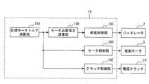
- FIG. 3 is a block diagram of arithmetic processing executed by the 4WD controller 19.
- the 4WD controller 19 includes a target motor torque calculation unit 19A, a required motor power calculation unit 19B, a power generation control unit 19C, and a motor control unit 19D.
- the control of the main relay and the electromagnetic clutch 10 will not be described in detail, but the 4WD controller 19 outputs a relay control command to the main relay when controlling the drive of the electric motor 3 to the electric motor 3. It is assumed that the electric power supply is controlled to the ON state, and the clutch control command to the electromagnetic clutch 11 is output to control the electromagnetic clutch 10 to the engaged state.
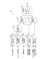
- FIG. 4 is a block diagram of the target motor torque calculation unit 19A.
- the target motor torque calculation unit 19A includes a first motor torque calculation unit 51, a first limit value calculation unit 52, a second limit value calculation unit 53, a second motor torque calculation unit 54, and a surplus torque calculation unit 55. , Selection unit 56, selection unit 57, selection unit 58, and switching unit 59.
- the first motor torque calculation unit 51 calculates the power distribution ratio ⁇ from the accelerator opening Acc with reference to the map of FIG. 5, and calculates the first motor torque Tm1 according to the power distribution ratio ⁇ .
- the power distribution ratio ⁇ is a ratio for distributing the power of the engine 2 to the power of the electric motor 3 when converting the power of the engine 2 to the power of the electric motor 3.
- FIG. 5 is a map used for calculation of the power distribution ratio ⁇ according to the accelerator opening Acc.
- A1 to A4 having a relationship of 0 ⁇ A1 ⁇ A2 ⁇ A3 ⁇ A4 are determined in advance, and for the power distribution ratio, ⁇ 1 (for example, 20%) having a relationship of ⁇ 1> ⁇ 2.
- ⁇ 2 for example, 12%) are predetermined.
- the accelerator opening Acc is in the range of 0 to A1
- the power distribution ratio ⁇ is maintained at 0, and when the accelerator opening Acc is in the range of A1 to A2, the power distribution is larger as the accelerator opening Acc is larger.
- the ratio ⁇ increases from 0 to ⁇ 1.
- the power distribution ratio ⁇ maintains ⁇ 1
- the power distribution is larger as the accelerator opening Acc is larger.
- the ratio decreases from ⁇ 1 to ⁇ 2.
- the power distribution ratio ⁇ maintains ⁇ 2.
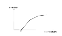
- the first limit value calculation unit 52 calculates a first limit value TL1 from the engine speed Ne with reference to the map of FIG. FIG. 6 is a map used to calculate the first limit value TL1.
- N1 which has a relationship of 0 ⁇ N1 is predetermined for the engine rotational speed Ne.
- the first limit value TL1 is maintained at 0, and when the engine speed Ne is larger than N1, the first limit value TL1 increases as the engine speed Ne increases. Increases from 0.
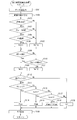
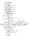
- FIG. 7 is a flowchart showing the second limit value calculation process.
- step S101 various data are read and then the process proceeds to step S102.
- step S102 the road surface gradient ⁇ [%] is calculated according to the acceleration / deceleration, and then the process proceeds to step S103.
- the road surface gradient ⁇ is calculated as (vertical distance / horizontal distance) ⁇ 100, and the upward slope side is represented by a positive value (+), and the downward slope side is represented by a negative value ( ⁇ ).
- a low-pass filter process of 1 Hz is performed on the road surface gradient ⁇ .
- step S103 it is determined whether or not the host vehicle is in a stopped state.
- the vehicle speed V is zero.
- the process proceeds to step S104.
- the vehicle speed V is greater than 0, it is determined that the host vehicle is in the traveling state, and the process proceeds to step S107.
- step S104 it is determined whether the brake is on.
- the brake is on, it is determined that the vehicle is in the braking state, and the process proceeds to step S105.
- the brake is off, it is determined that the vehicle is not in the braking state, and the process proceeds to step S107.
- step S105 it is determined whether or not a predetermined time t1 (for example, 1 sec) has elapsed since the host vehicle is in a stopped state and in a braking state.
- t1 a predetermined time
- t1 it is determined that the road surface gradient ⁇ at the time of stopping has been detected
- step S108 it is determined whether or not the setting has been switched from four-wheel drive to two-wheel drive.
- step S109 it is determined whether four-wheel drive is set in the previous and previous calculations, and two-wheel drive is set in the present calculation.
- the process proceeds to step S109.
- the process proceeds to step S110.
- step S110 it is determined whether or not there is an abnormality in the acceleration sensor 29.
- the process proceeds to step S109 described above.
- the process proceeds to step S111.
- step S112 it is determined whether the shift position of the transmission is set to the travel range.
- the shift position is set to the travel range such as the forward range (D or 1st gear) or the reverse range (R)
- the process proceeds to step S113.
- the shift position is not set to the travel range such as the forward range (D or 1st gear) or the reverse range (R)
- the shift position is not set to the travel range such as the forward range (D or 1st gear) or the reverse range (R)
- the shift position is not set to the travel range such as the forward range (D or 1st gear) or the reverse range (R)
- the parking range (P) or the neutral range (N) etc.
- step S113 it is determined whether the shift position of the transmission is set to the reverse range (R).
- the process proceeds to step S114.
- the shift position is not set to the reverse range (R), that is, set to the forward range (D or 1st gear)
- the process moves to step S115.
- step S114 the power distribution ratio ⁇ is set to a predetermined maximum value ⁇ MAX (for example, 20%), and then the process proceeds to step S120.
- the process proceeds to step S116.
- step S116 the power distribution ratio ⁇ is set to a predetermined minimum value ⁇ MIN (for example, 5%), and then the process proceeds to step S120.
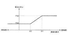
- step S118 the power distribution ratio ⁇ is set according to the road surface gradient ⁇ with reference to the map of FIG. 8, and then the process proceeds to step S120.
- FIG. 8 is a map used to set the power distribution ratio ⁇ according to the road surface gradient ⁇ .
- ⁇ 2 for example, 10%
- ⁇ 1 for example, 15%
- the power distribution ratio ⁇ maintains the minimum value ⁇ MIN .
- the power distribution ratio increases as the road surface gradient ⁇ increases.
- the ratio ⁇ increases from the minimum value ⁇ MIN to the maximum value ⁇ MAX . Further, when the road surface gradient ⁇ is larger than ⁇ 1, the power distribution ratio ⁇ maintains the maximum value ⁇ MAX . When the road surface gradient ⁇ is on the downhill side (negative side), the power distribution ratio ⁇ maintains the minimum value ⁇ MIN .
- the power distribution ratio ⁇ is set to the previous value ⁇ z, and then the process proceeds to step S120.
- the second limit value TL2 is calculated according to the power distribution ratio ⁇ , and then the process returns to the predetermined main program.
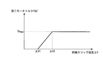
- the second motor torque calculation unit 54 calculates a second motor torque Tm2 from the front wheel slip velocity ⁇ V with reference to the map of FIG.
- the front wheel slip speed ⁇ V is calculated, for example, by subtracting the average wheel speed Vwr of the rear wheels 1RL and 1RR from the average wheel speed Vwf of the front wheels 1FL and 1FR, as shown in the following equation (1).
- Vwf (Vw FL + Vw FR ) / 2
- FIG. 9 is a map used to calculate the second motor torque Tm2.
- the front wheel slip speed ⁇ V is in the range of 0 to ⁇ V1
- the second motor torque Tm2 is maintained at 0, and when the front wheel slip speed ⁇ V is in the range of ⁇ V1 to ⁇ V2, the larger the front wheel slip speed ⁇ V, second motor torque Tm2 increases from 0 to the maximum value T MAX.
- the front wheel slip velocity ⁇ V is larger than ⁇ V2, the second motor torque Tm2 maintains the maximum value T MAX .
- FIG. 10 is a flowchart showing surplus torque calculation processing.
- step S201 various data are read and then the process proceeds to step S202.
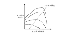
- step S202 the engine torque Te is calculated (estimated) according to the engine rotational speed Ne and the accelerator opening Acc with reference to the map of FIG. 11, and then the process proceeds to step S203.
- FIG. 11 is a map used to calculate the engine torque Te.
- the engine torque Te increases as the accelerator opening Acc increases. Then, in a region where the accelerator opening Acc is relatively small, the engine torque Te decreases according to the increase of the engine rotational speed Ne. Further, in a region where the accelerator opening Acc is relatively large, the engine torque Te initially increases in response to the increase of the engine speed Ne, and suddenly decreases from a certain position.
- step S203 the load torque Tg of the generator 7 is calculated according to the voltage V of the generator 7, the armature current Ia, and the rotation speed Ng, as shown in the following equation (2), and then the process proceeds to step S204.
- K2 and K3 are predetermined coefficients.
- Tg K2 ⁇ (V ⁇ Ia) / (K3 ⁇ Ng) ...
- step S204 the acceleration torque Ta of the front wheels is calculated according to the moment of inertia J and the angular acceleration a, as shown in the following equation (3), and then the process proceeds to step S205.
- the moment of inertia J is the inertia of the drive system including the gear ratio.
- step S205 as shown in the following equation (4), the front wheel driving force Tf is calculated according to the engine torque Te, the load torque Tg, and the acceleration torque Ta, and then the process proceeds to step S206.
- Rt is the amplification ratio of the torque converter
- Rg is the gear ratio of the transmission.
- the front wheel driving force Tf corresponds to the road surface reaction force for the front wheels 1FL and 1FR.
- Tf (Te-Tg) ⁇ (Rt ⁇ Rg) -Ta (4)
- step S206 it is determined whether the host vehicle is traveling.
- the vehicle speed V is greater than zero.
- the vehicle speed V is 0, it is determined that the host vehicle is not in the traveling state, that is, in the stopped state, and the process proceeds to step S207.
- the vehicle speed V is greater than 0, it is determined that the host vehicle is in the traveling state, and the process proceeds to step S208.
- the stored maximum value Tf MAX is reset to 0, and then the process proceeds to step S215.
- step S208 it is determined whether the front wheels have a tendency to slip.
- the front wheel slip speed ⁇ V is less than a predetermined threshold th.
- the front wheel slip speed ⁇ V is less than the threshold value th, it is determined that there is no tendency for the front wheels to slip, and the process proceeds to step S209.
- the front wheel slip speed ⁇ V is equal to or higher than the threshold th, it is determined that the front wheels have a slip tendency, and the process proceeds to step S212.
- step S209 it determines whether or not the maximum value larger than Tf MAX of front wheel drive force Tf is stored.
- the front wheel drive force Tf is greater than the maximum value Tf MAX, it is determined that it is necessary to update the maximum value Tf MAX proceeds to step S210.
- the front wheel drive force Tf is less than or equal to the maximum value Tf MAX is updated maximum value Tf MAX, it is determined that it is not necessary the process proceeds to step S211.
- step S210 the process proceeds after updating the stored maximum value Tf MAX to the current front wheel drive force Tf to step S215.
- the process proceeds to step S215 to maintain the maximum value Tf MAX that stored.
- step S212 the determining whether the maximum value Tf MAX less than or not the front wheel drive force Tf is stored.
- the front wheel drive force Tf is less than the maximum value Tf MAX, it is determined that it is necessary to update the maximum value Tf MAX proceeds to step S213.
- the front wheel drive force Tf is equal to or more than the maximum value Tf MAX is updated maximum value Tf MAX, it is determined that it is not necessary the process proceeds to step S214.
- step S213 the process proceeds after updating the stored maximum value Tf MAX to the current front wheel drive force Tf to step S215.
- the process proceeds to step S215 to maintain the maximum value Tf MAX that stored.
- step S215 as shown in the following equation (5), the limit torque Te MAX with respect to the engine torque Te is calculated according to the stored maximum value Tf MAX , and then the process proceeds to step S216.
- Rt is the amplification ratio of the torque converter
- Rg is the gear ratio of the transmission.
- the limit torque Te MAX corresponds to the upper limit value that can suppress the acceleration slip of the front wheels 1FL and 1FR.
- Te MAX Tf MAX / (Rt x Rg) fashioned (5)
- step S216 it is determined whether the engine torque Te is larger than the limit torque Te MAX .
- the engine torque Te is larger than the limit torque Te MAX, it is determined that the engine torque Te has the surplus torque Tp, and the process proceeds to step S217.
- the engine torque Te is equal to or less than the limit torque Te MAX, it is determined that there is no excess torque Tp in the engine torque Te, and the process proceeds to step S218.
- step S217 as shown in the following equation (6), the limit torque Te MAX is subtracted from the engine torque Te to calculate the surplus torque Tp, and then the process returns to the predetermined main program.
- Tp Te-Te MAX alone (6)
- step S218 the surplus torque Tp is reset to 0 and then the process returns to the predetermined main program.
- the selection process performed by the selection unit 56 will be described.
- the smallest one of the first motor torque Tm1, the first limit value TL1, and the second limit value TL2 is calculated as a new first motor torque Tm1, as shown in the following equation (7).
- Tm1 min [Tm1, TL1, TL2] ... (7)
- the selection unit 57 calculates the largest one of the first motor torque Tm1 and the second motor torque Tm2 as the starting motor torque TS, as shown in the following equation (8).
- TS max [Tm1, Tm2] ... (8)
- the selection unit 58 calculates the largest one of the second motor torque Tm2 and the surplus torque Tp as the traveling motor torque TD, as shown in the following equation (9).
- TD max [Tm2, Tp] ; (9)
- the switching unit 59 determines whether the vehicle speed V is equal to or less than a predetermined threshold value Vs (for example, 5 km / h).
- a predetermined threshold value Vs for example, 5 km / h.
- the starting motor torque TS is output as the final target motor torque Tm * .
- the running motor torque TD is output as the final target motor torque Tm * .
- the required motor power calculation unit 19B calculates the required motor power Pm * required for the electric motor 3 according to the target motor torque Tm * and the motor rotational speed Nm, as shown in the following equation (10).
- Pm * Tm * ⁇ Nm ... (10)
- FIG. 12 is a block diagram of the power generation control unit 19C.
- the power generation control unit 19C includes a target power calculation unit 40, a limit value calculation unit 41, a final target power calculation unit 42, and a control processing unit 43.
- calculation processing executed by the target power calculation unit 40 will be described.
- the target power calculation unit 40 calculates the target power Pg * to be output by the generator 7 according to the motor required power Pm * and the motor efficiency ⁇ m, as shown in the following equation (11).
- Pg * Pm * / ⁇ m (......) (11)
- the limit value calculator 41 calculates limit values PL1 and PL2 for the output power.
- the limit value PL1 is an upper limit value capable of suppressing the belt slip of the V-belt 6, and as shown in the following equation (12), the torque upper limit value TL to which the V-belt 6 can transmit, the generator rotational speed Ng, Calculated according to the generator efficiency ⁇ g.
- PL1 TL ⁇ Ng ⁇ ⁇ g (12)
- the limit value PL2 is an upper limit value capable of suppressing engine stall and drivability deterioration caused by overload of the engine 2, and may be calculated according to the engine speed Ne or may be a predetermined value.
- the target power Pg * of limiting values PL1, and PL2, calculates the smallest as the final target power Pg *.
- Pg * min [Pg * , PL1, PL2] .
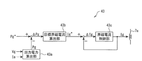
- FIG. 13 is a block diagram of the control processing unit 43. As shown in FIG.
- the control processing unit 43 includes an output power calculation unit 43a, a target field current calculation unit 43b, and a field current control unit 43c.
- the actual field current Ig is detected by a current sensor.
- the motor control unit 19D first calculates the target motor field current Im * from the motor rotational speed Nm.
- the target motor field current Im * is reduced by well-known field weakening control when the motor rotational speed Nm reaches a high speed range. That is, when the electric motor 3 rotates at high speed, the induced voltage increases and the motor torque Tm decreases. Therefore, the increase of the induced voltage is suppressed by reducing the field current Im, and the decrease in the motor torque Tm is prevented. Then, the field current Im of the electric motor 3 is adjusted to the target motor field current Im * so that the target motor torque Tm * is output.
- the clutch control unit 19E when the target motor torque Tm * is 0, power transmission from the electric motor 3 to the rear wheels 1RL and 1RR is cut off by controlling the electromagnetic clutch 10 in the non-engaged state, and the target motor torque Tm When * is larger than 0, power transmission from the electric motor 3 to the rear wheels 1RL and 1RR is performed by controlling the electromagnetic clutch 10 in the engaged state.
- the target motor torque Tm * mainly depends on the first motor torque Tm1 corresponding to the accelerator opening Acc, the second motor torque Tm2 corresponding to the front wheel slip speed ⁇ V, and the surplus torque Tp exceeding the limit torque Te MAX. Calculated.
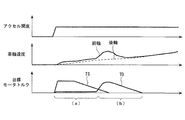
- FIG. 14 is a time chart showing the transition of the target motor torque Tm * .
- the start motor torque TS obtained by the select high of the first motor torque Tm1 and the second motor torque Tm2 is output as the final target motor torque Tm * .
- the target motor torque Tm * corresponding to the front wheel slip velocity ⁇ V is output, and as shown in FIG. 14A, acceleration slip is generated on the front wheels 1FL and 1FR. Even when it does not occur, the target motor torque Tm * corresponding to the accelerator opening Acc is output.
- the one with high priority can be reflected in the target motor torque Tm * .
- the running motor torque TD obtained by the selection high of the second motor torque Tm2 and the surplus torque Tp is output as the final target motor torque Tm * .
- the target motor torque Tm * corresponding to the front wheel slip velocity ⁇ V is output, and acceleration slip is generated on the front wheels 1FL and 1FR.
- the target motor torque Tm * corresponding to the surplus torque Tp estimated to exceed the limit torque Te MAX is output.
- the limit torque Te MAX is constantly updated according to the road surface condition. That is, in a state where front wheels 1FL and 1FR are not slipping due to acceleration (determination in S208 is "Yes"), when front wheel driving force Tf is larger than maximum value Tf MAX (determination in S209 is “Yes"), engine torque Te There is still room for reaching the limit torque Te MAX . In such a case, since it is considered that the friction coefficient of the road surface is rising, the limit torque Te MAX is raised by updating the maximum value Tf MAX to the current front wheel driving force Tf (S210).
- the required power Pm * required for the electric motor 3 is calculated, and the target power Pg * to be output by the generator 7 is calculated from the required power Pm * , and this target power Pg * is the actual output power Pg and Since the field current Ig of the generator 7 is controlled to coincide with each other, the generator 7 can accurately supply the required electric power Pm * required for the electric motor 3 and accurately output the target motor torque Tm *. be able to.
- the field current Ig of the generator 7 is detected by a current sensor, and feedback control is performed so that the actual field current Ig follows the target field current Ig *. Therefore, the output power Pg is reliably set to the target power Pg *. Can follow.
- the present invention is not limited to this.
- the first motor torque Tm1 may be calculated according to the slip tendency of the front wheels 1FL and 1FR, so the first motor torque Tm1 may be calculated according to the wheel acceleration and slip ratio of the front wheels 1FL and 1FR, for example.
- the front wheels 1FL and 1FR are the main drive wheels driven by the engine 2
- the rear wheels 1RL and 1RR are the auxiliary drive wheels that can be driven by the electric motor 3.
- the rear wheels 1RL and 1RR may be main driving wheels
- the front wheels 1FL and 1FR may be auxiliary driving wheels.
- the power train of the 1 motor system which drives rear-wheel 1RL * 1RR with one electric motor 3 is employ
- adopted it is not limited to this.
- a two-motor system in which the left and right wheels are separately driven by two electric motors, or an in-wheel motor system in which the motors are disposed under the spring (wheel side) may be adopted.
- a direct current motor is used as the electric motor 3 in the present embodiment, an alternating current motor may be used.
- the present invention is applied to a four-wheeled vehicle, but may be applied to a two-wheeled vehicle, a three-wheeled vehicle, or a vehicle of five or more wheels.
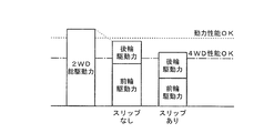
- FIG. 15 is a diagram for explaining the power performance and the four-wheel drive performance.
- the rear wheel drive force is generated from a part of the engine torque, so when trying to increase the power distribution ratio from the engine torque to the rear wheel drive force, the total drive force of the vehicle is reduced by the loss based on the conversion efficiency. Resulting in.
- acceleration slip is likely to occur on the front wheels 1FL and 1FR, smooth and stable start and traveling can be realized by increasing the power distribution ratio ⁇ , so there is more to compensate for the reduction of the power performance 4 Wheel drive performance can be exhibited.
- the power distribution ratio ⁇ from the engine torque Te to the motor torque Tm is set when the engine torque Te is partially converted to the motor torque Tm via the generator 7, and the road surface gradient ⁇ Is smaller on the uphill side, the power distribution ratio ⁇ is limited (step S118). Specifically, when the road surface gradient ⁇ is equal to or higher than ⁇ 1 (for example, 15%) predetermined on the uphill side, the power distribution ratio ⁇ is set to a predetermined maximum value ⁇ MAX (for example, 20%), and the road surface gradient ⁇ is When it is less than ⁇ 2 (for example, 10%) smaller than ⁇ 1 on the uphill side, the power distribution ratio ⁇ is set to the minimum value ⁇ MIN (for example, 5%).
- the power distribution ratio ⁇ is set smaller in the range from the maximum value ⁇ MAX to the minimum value ⁇ MIN as the road surface gradient ⁇ is smaller on the uphill side.
- the second limit value TL2 according to the power distribution ratio ⁇ is set (step S120), and the first motor torque Tm1 according to the accelerator opening Acc is limited to the second limit value TL2 or less. That is, by the selection process executed by the selection unit 56, the smallest one of the first motor torque Tm1 and the second limit value TL2 is calculated as the new first motor torque Tm1.
- the energy loss based on the conversion efficiency can be reduced by limiting the power distribution ratio ⁇ as the road surface slope ⁇ becomes smaller on the uphill side, that is, as acceleration slip of the front wheels 1FL and 1FR becomes less likely
- the total driving force can be secured according to the driver's acceleration request. Therefore, even in the case of a vehicle having a small displacement of an engine such as, for example, a three-cylinder engine, it is possible to suppress a decrease in acceleration performance such as shakiness at the time of start.
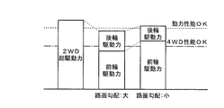
- FIG. 16 is a diagram for explaining the power performance and the four-wheel drive performance of the present embodiment.
- the restriction on the power distribution ratio ⁇ is relaxed and the power distribution ratio ⁇ is the maximum value ⁇ MAX (eg 20% Allow up to).
- ⁇ MAX the maximum value
- the power distribution ratio ⁇ is continuously changed in the range of ⁇ 1 to ⁇ 2, but the present invention is not limited to this. It may be changed into a shape. Also, it may be one step only, or may be configured to be switched between the maximum value ⁇ MAX and the minimum value ⁇ MIN . Further, in the present embodiment, the power distribution ratio ⁇ is set according to the accelerator opening Acc, and then converted to the first motor torque Tm1, or the power distribution ratio ⁇ is limited according to the road surface gradient ⁇ . Although two limit value TL2 is converted, it is not limited to this. For example, with reference to the map of FIG. 17, the first motor torque Tm1 may be directly calculated according to the accelerator opening Acc, or with reference to the map of FIG. The limit value TL2 may be calculated.
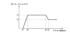
- FIG. 17 is a map used to calculate the first motor torque Tm1.
- A1 to A4 having a relationship of 0 ⁇ A1 ⁇ A2 ⁇ A3 ⁇ A4 are predetermined for the accelerator opening Acc, and T1 (for example, 10 Nm) having a relationship of T1> T2 for the first motor torque Tm1.
- T2 (for example, 6 Nm) are predetermined.
- the accelerator opening Acc is in the range of 0 to A1
- the first motor torque Tm1 is maintained at 0, and when the accelerator opening Acc is in the range of A1 to A2, the larger the accelerator opening Acc,
- One motor torque Tm1 increases from 0 to T1.
- the first motor torque Tm1 maintains T1
- the accelerator opening Acc is in the range of A2 to A3
- the larger the accelerator opening Acc One motor torque Tm1 decreases from T1 to T2.
- the first motor torque Tm1 maintains T2.
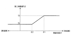
- FIG. 18 is a map used to calculate the second limit value TL2.
- ⁇ 2 for example, 10%
- ⁇ 1 for example, 15%
- T4 for example, 3 Nm
- T3 for example, 10 Nm
- TL2 increases from T4 to T3.
- the second limit value TL2 maintains T3.
- the second limit value TL2 maintains T4.
- the driving force of the electric motor 3 is restricted to a small value by restricting the power distribution ratio ⁇ to a small value, but the invention is not limited to this.
- the driving force of the electric motor 3 can be limited to a small value, so the driving force of the electric motor 3 can be reduced by restricting the command value (for example, target motor torque Tm * ) of the electric motor 3 to a small value. May be limited to a small size.
- the driving force of the electric motor 3 may be limited to a small value by limiting the power generation command value (for example, the target power Pg * ) to the generator 7 to a small value.
- the front wheels 1FL and 1FR correspond to “main drive wheels”
- the rear wheels 1RL and 1RR correspond to “auxiliary drive wheels”
- the generator 7 corresponds to "generator”.
- the 4WD controller 19 corresponds to the “electric motor limiting unit”
- the first motor torque calculating unit 51, the second limiting value calculating unit 53, and the selecting unit 56 correspond to the “distribution ratio setting unit”.
- the power distribution ratio ⁇ set by the first motor torque calculation unit 51 corresponds to the “first power distribution ratio”
- the power distribution ratio ⁇ set by the second limit value calculation unit 53 is “second”. It corresponds to "power distribution ratio”.
- the rear wheel 1 RL is generated by the electric power generated by the engine 2 that drives the front wheels 1FL and 1FR, the generator 7 that generates power by obtaining the power of the engine 2, and the generator 7 -The electric motor 3 which drives 1 RR is provided.
- the motor torque Tm is made smaller as the road surface gradient ⁇ is smaller on the uphill side.
- the power distribution ratio ⁇ is limited as the road surface gradient ⁇ is smaller on the uphill side.
- energy loss based on conversion efficiency can be reduced and a total driving force according to the driver's acceleration request can be secured. it can. Therefore, even if the vehicle has a small displacement of the engine 2, it is possible to suppress a decrease in acceleration performance such as rattling at the time of start.
- the power distribution ratio ⁇ is set to the predetermined maximum value ⁇ MAX when the road surface gradient ⁇ is equal to or larger than the predetermined ⁇ 1 on the uphill side.
- the power distribution ratio ⁇ is set to the minimum value ⁇ MIN .
- the power distribution ratio ⁇ is set smaller in the range from the maximum value ⁇ MAX to the minimum value ⁇ MIN as the road surface gradient ⁇ is smaller on the uphill side.
- the first motor torque Tm1 is set by the power distribution ratio ⁇ according to the accelerator opening Acc, and the second motor torque Tm1 is set according to the road surface gradient ⁇ .
- the smallest one of the first motor torque Tm1 and the second limit value TL2 is calculated as a new first motor torque Tm1.
- the target motor torque Tm * by the select low of the first motor torque Tm1 and the second limit value TL2
- the total drive according to the driver's acceleration request is ensured while securing the four-wheel drive performance. Power can be realized and power performance can be enhanced.
- the front wheels 1FL and 1FR are driven by the engine 2, the power of the engine 2 is obtained, the generator 7 generates power, and the electric power generated by the generator 7 generates the electric motor 3 Drive the rear wheels 1RL and 1RR.
- the power distribution ratio ⁇ from the engine torque Te to the motor torque Tm is set at the time of converting a part of the engine torque Te into the motor torque Tm via the generator 7, and the road surface gradient ⁇ is smaller on the uphill
- the motor torque Tm is limited to a small value.
- the energy loss based on the conversion efficiency can be reduced by limiting the power distribution ratio ⁇ as the road surface slope ⁇ becomes smaller on the uphill side, that is, as acceleration slip of the front wheels 1FL and 1FR becomes less likely
- the total driving force can be secured according to the driver's acceleration request. Therefore, even if the vehicle has a small displacement of the engine 2, it is possible to suppress a decrease in acceleration performance such as rattling at the time of start.
Landscapes
- Engineering & Computer Science (AREA)
- Transportation (AREA)
- Mechanical Engineering (AREA)
- Chemical & Material Sciences (AREA)
- Combustion & Propulsion (AREA)
- Power Engineering (AREA)
- Automation & Control Theory (AREA)
- Sustainable Energy (AREA)
- Sustainable Development (AREA)
- Life Sciences & Earth Sciences (AREA)
- Hybrid Electric Vehicles (AREA)
- Arrangement And Driving Of Transmission Devices (AREA)
- Electric Propulsion And Braking For Vehicles (AREA)
Priority Applications (1)
| Application Number | Priority Date | Filing Date | Title |
|---|---|---|---|
| US14/380,275 US9308807B2 (en) | 2012-02-27 | 2013-02-18 | Vehicle drive control apparatus, and vehicle drive control method |
Applications Claiming Priority (2)
| Application Number | Priority Date | Filing Date | Title |
|---|---|---|---|
| JP2012040363A JP5966428B2 (ja) | 2012-02-27 | 2012-02-27 | 車両用駆動制御装置、車両用駆動制御方法 |
| JP2012-040363 | 2012-02-27 |
Publications (1)
| Publication Number | Publication Date |
|---|---|
| WO2013128837A1 true WO2013128837A1 (ja) | 2013-09-06 |
Family
ID=49082053
Family Applications (1)
| Application Number | Title | Priority Date | Filing Date |
|---|---|---|---|
| PCT/JP2013/000877 Ceased WO2013128837A1 (ja) | 2012-02-27 | 2013-02-18 | 車両用駆動制御装置、車両用駆動制御方法 |
Country Status (3)
| Country | Link |
|---|---|
| US (1) | US9308807B2 (enExample) |
| JP (1) | JP5966428B2 (enExample) |
| WO (1) | WO2013128837A1 (enExample) |
Cited By (2)
| Publication number | Priority date | Publication date | Assignee | Title |
|---|---|---|---|---|
| CN110014851A (zh) * | 2019-04-10 | 2019-07-16 | 中国第一汽车股份有限公司 | 一种前后双电机四驱车辆轴间扭矩分配方法 |
| CN110103940A (zh) * | 2019-04-01 | 2019-08-09 | 浙江吉利汽车研究院有限公司 | 一种bsg电机扭矩控制方法、装置及设备 |
Families Citing this family (28)
| Publication number | Priority date | Publication date | Assignee | Title |
|---|---|---|---|---|
| JPWO2015034025A1 (ja) | 2013-09-04 | 2017-03-02 | 本田技研工業株式会社 | ハイブリッド車両用駆動装置 |
| US9827969B2 (en) * | 2013-12-12 | 2017-11-28 | Ford Global Technologies, Llc | Controlling powertrain torque in a hybrid vehicle |
| JP6402472B2 (ja) * | 2014-04-08 | 2018-10-10 | 日産自動車株式会社 | 車両用駆動制御装置及び車両用駆動制御方法 |
| CN106715175B (zh) | 2014-09-29 | 2020-03-17 | 斯堪尼亚商用车有限公司 | 混合动力总成和用于控制该混合动力总成的方法 |
| SE539232C2 (sv) | 2014-09-29 | 2017-05-23 | Scania Cv Ab | Förfarande för att styra en hybriddrivlina, fordon med en sådan hybriddrivlina, dator-program för att styra en sådan hybriddrivlina, samt en datorprogramprodukt innefattande programkod |
| SE540406C2 (sv) * | 2014-09-29 | 2018-09-11 | Scania Cv Ab | Förfarande för att styra en hybriddrivlina, fordon med en sådan hybriddrivlina, datorprogram för att styra en sådan hybriddrivlina, samt en datorprogramprodukt innefattande programkod |
| SE539295C2 (sv) | 2014-09-29 | 2017-06-20 | Scania Cv Ab | Hybriddrivlina innefattande en rangeväxel och ett fordon meden sådan hybriddrivlina |
| US10703215B2 (en) | 2014-10-20 | 2020-07-07 | Ford Global Technologies, Llc | Hybrid powertrain speed control |
| EP3317154B1 (en) | 2015-07-02 | 2020-03-25 | Volvo Truck Corporation | A method for controlling a hydraulic hybrid vehicle |
| DE102015118759A1 (de) | 2015-11-02 | 2017-05-04 | Gkn Driveline International Gmbh | Verfahren zur Steuerung eines Antriebsmoments und Antriebsstranganordnung zur Durchführung des Verfahrens |
| JP6439722B2 (ja) * | 2016-03-08 | 2018-12-19 | トヨタ自動車株式会社 | ハイブリッド自動車 |
| JP6819547B2 (ja) * | 2017-11-13 | 2021-01-27 | トヨタ自動車株式会社 | 車両の駆動力制御装置 |
| CN108437992B (zh) * | 2018-04-27 | 2019-12-31 | 中国第一汽车股份有限公司 | 利用纵向加速度传感器检测车辆溜车状态的方法 |
| CN109849683B (zh) * | 2018-08-22 | 2022-06-03 | 武汉理工大学 | 一种基于无人驾驶电动汽车的坡道防溜控制方法 |
| CN109367400B (zh) * | 2018-09-19 | 2020-09-11 | 吉利汽车研究院(宁波)有限公司 | 一种电动汽车起步阶段的扭矩仲裁方法及装置 |
| CN109849685B (zh) * | 2019-01-23 | 2020-08-18 | 江苏敏安电动汽车有限公司 | 一种电动汽车防遛坡扭矩控制算法 |
| CN110562048B (zh) * | 2019-09-03 | 2021-02-19 | 广东轻工职业技术学院 | 新能源汽车的复合驱动系统的能量分配方法 |
| KR102213252B1 (ko) * | 2019-11-04 | 2021-02-08 | 주식회사 현대케피코 | 토크 제어 방법 |
| CN110758124A (zh) * | 2019-12-05 | 2020-02-07 | 重庆隆鑫机车有限公司 | 电动车增程器控制系统 |
| CN113306406B (zh) * | 2020-02-26 | 2022-10-28 | 北京新能源汽车股份有限公司 | 一种电机扭矩控制装置、方法及汽车 |
| GB2594276B (en) * | 2020-04-21 | 2023-02-22 | Jaguar Land Rover Ltd | Maintaining multi-axle drive capability in a hybrid vehicle |
| CN113715597B (zh) * | 2020-05-21 | 2023-02-03 | 华为数字能源技术有限公司 | 动力驱动系统及车辆 |
| CN113085582B (zh) * | 2021-04-23 | 2023-03-03 | 联合汽车电子有限公司 | 新能源汽车双驱动电机实时控制方法、存储介质、控制器和系统 |
| DE102021112440A1 (de) * | 2021-05-12 | 2022-11-17 | Bayerische Motoren Werke Aktiengesellschaft | Steuervorrichtung zum Betrieb eines straßengekoppelten Allradfahrzeuges |
| US11965476B2 (en) * | 2021-07-28 | 2024-04-23 | Ford Global Technologies, Llc | Methods and system for starting an engine |
| CN115139815B (zh) * | 2022-06-27 | 2024-04-09 | 重庆金康赛力斯新能源汽车设计院有限公司 | 扭矩分配方法、装置、设备和存储介质 |
| SE546835C2 (en) | 2023-04-24 | 2025-02-25 | Scania Cv Ab | Method of Controlling Operation of a Vehicle, Computer Program, Computer-readable medium, Control Arrangement, and Vehicle |
| WO2025031582A1 (en) * | 2023-08-09 | 2025-02-13 | Volvo Truck Corporation | Motor control |
Citations (8)
| Publication number | Priority date | Publication date | Assignee | Title |
|---|---|---|---|---|
| JP2000083301A (ja) * | 1998-09-04 | 2000-03-21 | Toyota Motor Corp | 前後輪駆動車両の制御装置 |
| JP2000079828A (ja) * | 1998-09-04 | 2000-03-21 | Toyota Motor Corp | 前後輪駆動車両の制御装置 |
| JP2002030952A (ja) * | 2000-07-19 | 2002-01-31 | Honda Motor Co Ltd | 前後輪駆動車両の駆動力制御装置 |
| JP2004084581A (ja) * | 2002-08-27 | 2004-03-18 | Nissan Motor Co Ltd | 四輪駆動車両の駆動力制御装置 |
| JP2004098715A (ja) * | 2002-09-04 | 2004-04-02 | Nissan Motor Co Ltd | 車両の駆動力制御装置 |
| JP2005059851A (ja) * | 1999-10-08 | 2005-03-10 | Toyota Motor Corp | 4輪駆動車の制御装置 |
| JP2005161961A (ja) * | 2003-12-02 | 2005-06-23 | Toyota Motor Corp | 自動車 |
| JP2008201182A (ja) * | 2007-02-16 | 2008-09-04 | Toyota Motor Corp | ハイブリッド車両の駆動装置 |
Family Cites Families (8)
| Publication number | Priority date | Publication date | Assignee | Title |
|---|---|---|---|---|
| FR2799417B1 (fr) | 1999-10-08 | 2009-01-23 | Toyota Motor Co Ltd | Dispositif de controle de vehicule, notamment pour la repartition des forces de traction avant-arriere |
| DE60113216T2 (de) | 2000-11-14 | 2006-02-23 | Nissan Motor Co., Ltd., Yokohama | Antriebskraftsteuerungsvorrichtung |
| JP3702892B2 (ja) | 2000-11-14 | 2005-10-05 | 日産自動車株式会社 | 車両の駆動力制御装置 |
| JP4225314B2 (ja) * | 2005-12-26 | 2009-02-18 | トヨタ自動車株式会社 | ハイブリッド車両 |
| US8448731B2 (en) * | 2007-11-05 | 2013-05-28 | GM Global Technology Operations LLC | Method and apparatus for determination of fast actuating engine torque for a hybrid powertrain system |
| US8061464B2 (en) * | 2008-04-09 | 2011-11-22 | Ford Global Technologies, Llc | Traction and stability control system and method for a vehicle with mechanically independent front and rear traction wheels |
| DE102010015423A1 (de) * | 2010-04-19 | 2011-10-20 | Audi Ag | Antriebsvorrichtung für ein allradgetriebenes Fahrzeug |
| JP5501260B2 (ja) * | 2011-02-03 | 2014-05-21 | ジヤトコ株式会社 | 車両の制御装置 |
-
2012
- 2012-02-27 JP JP2012040363A patent/JP5966428B2/ja not_active Expired - Fee Related
-
2013
- 2013-02-18 US US14/380,275 patent/US9308807B2/en not_active Expired - Fee Related
- 2013-02-18 WO PCT/JP2013/000877 patent/WO2013128837A1/ja not_active Ceased
Patent Citations (8)
| Publication number | Priority date | Publication date | Assignee | Title |
|---|---|---|---|---|
| JP2000083301A (ja) * | 1998-09-04 | 2000-03-21 | Toyota Motor Corp | 前後輪駆動車両の制御装置 |
| JP2000079828A (ja) * | 1998-09-04 | 2000-03-21 | Toyota Motor Corp | 前後輪駆動車両の制御装置 |
| JP2005059851A (ja) * | 1999-10-08 | 2005-03-10 | Toyota Motor Corp | 4輪駆動車の制御装置 |
| JP2002030952A (ja) * | 2000-07-19 | 2002-01-31 | Honda Motor Co Ltd | 前後輪駆動車両の駆動力制御装置 |
| JP2004084581A (ja) * | 2002-08-27 | 2004-03-18 | Nissan Motor Co Ltd | 四輪駆動車両の駆動力制御装置 |
| JP2004098715A (ja) * | 2002-09-04 | 2004-04-02 | Nissan Motor Co Ltd | 車両の駆動力制御装置 |
| JP2005161961A (ja) * | 2003-12-02 | 2005-06-23 | Toyota Motor Corp | 自動車 |
| JP2008201182A (ja) * | 2007-02-16 | 2008-09-04 | Toyota Motor Corp | ハイブリッド車両の駆動装置 |
Cited By (2)
| Publication number | Priority date | Publication date | Assignee | Title |
|---|---|---|---|---|
| CN110103940A (zh) * | 2019-04-01 | 2019-08-09 | 浙江吉利汽车研究院有限公司 | 一种bsg电机扭矩控制方法、装置及设备 |
| CN110014851A (zh) * | 2019-04-10 | 2019-07-16 | 中国第一汽车股份有限公司 | 一种前后双电机四驱车辆轴间扭矩分配方法 |
Also Published As
| Publication number | Publication date |
|---|---|
| US9308807B2 (en) | 2016-04-12 |
| JP2013173495A (ja) | 2013-09-05 |
| JP5966428B2 (ja) | 2016-08-10 |
| US20150038286A1 (en) | 2015-02-05 |
Similar Documents
| Publication | Publication Date | Title |
|---|---|---|
| JP5966428B2 (ja) | 車両用駆動制御装置、車両用駆動制御方法 | |
| JP3552710B2 (ja) | 車両の駆動力制御装置 | |
| JP5708822B2 (ja) | 車両用駆動制御装置、車両用駆動制御方法 | |
| US20080223634A1 (en) | Vehicle Drive System | |
| EP1535786A1 (en) | Acceleration slip control in four-wheel drive hybrid vehicle | |
| JP6553469B2 (ja) | 車両制御装置 | |
| JP5251380B2 (ja) | 制駆動制御装置及びそれを備えた車両 | |
| JP2003320859A (ja) | 4輪駆動車の駆動力制御装置 | |
| JP6079036B2 (ja) | 車両用駆動制御装置、車両用駆動制御方法 | |
| KR100623126B1 (ko) | 차량 구동력 제어 장치 | |
| JP5884910B2 (ja) | 車両用駆動制御装置 | |
| JP6402472B2 (ja) | 車両用駆動制御装置及び車両用駆動制御方法 | |
| JP2003159952A (ja) | 四輪駆動制御装置 | |
| JP3555617B2 (ja) | 車両の駆動力制御装置 | |
| JP2005185065A (ja) | 車両の駆動力制御装置 | |
| JP5668869B2 (ja) | 車両用駆動制御装置、車両用駆動制御方法 | |
| JP2010159020A (ja) | 車両の駆動制御装置及び駆動制御方法 | |
| JP2009214739A (ja) | 車両の駆動力制御装置 | |
| JP4165487B2 (ja) | 車両の駆動力制御装置 | |
| JP2008167586A (ja) | 車両用駆動制御装置 | |
| JP2006296068A (ja) | 車両用駆動制御装置 | |
| JP4182938B2 (ja) | 車両の駆動制御装置 | |
| US12441240B2 (en) | Electric vehicle driving aid method and system | |
| JP2006296131A (ja) | 車両用駆動制御装置 | |
| JP3933149B2 (ja) | 車両の駆動力制御装置 |
Legal Events
| Date | Code | Title | Description |
|---|---|---|---|
| 121 | Ep: the epo has been informed by wipo that ep was designated in this application |
Ref document number: 13755217 Country of ref document: EP Kind code of ref document: A1 |
|
| WWE | Wipo information: entry into national phase |
Ref document number: 14380275 Country of ref document: US |
|
| NENP | Non-entry into the national phase |
Ref country code: DE |
|
| 122 | Ep: pct application non-entry in european phase |
Ref document number: 13755217 Country of ref document: EP Kind code of ref document: A1 |