WO2013128690A1 - 油圧駆動システム - Google Patents
油圧駆動システム Download PDFInfo
- Publication number
- WO2013128690A1 WO2013128690A1 PCT/JP2012/073119 JP2012073119W WO2013128690A1 WO 2013128690 A1 WO2013128690 A1 WO 2013128690A1 JP 2012073119 W JP2012073119 W JP 2012073119W WO 2013128690 A1 WO2013128690 A1 WO 2013128690A1
- Authority
- WO
- WIPO (PCT)
- Prior art keywords
- hydraulic
- pump
- pressure
- charge
- flow path
- Prior art date
- Legal status (The legal status is an assumption and is not a legal conclusion. Google has not performed a legal analysis and makes no representation as to the accuracy of the status listed.)
- Ceased
Links
Images




Classifications
-
- F—MECHANICAL ENGINEERING; LIGHTING; HEATING; WEAPONS; BLASTING
- F15—FLUID-PRESSURE ACTUATORS; HYDRAULICS OR PNEUMATICS IN GENERAL
- F15B—SYSTEMS ACTING BY MEANS OF FLUIDS IN GENERAL; FLUID-PRESSURE ACTUATORS, e.g. SERVOMOTORS; DETAILS OF FLUID-PRESSURE SYSTEMS, NOT OTHERWISE PROVIDED FOR
- F15B1/00—Installations or systems with accumulators; Supply reservoir or sump assemblies
- F15B1/02—Installations or systems with accumulators
- F15B1/04—Accumulators
-
- E—FIXED CONSTRUCTIONS
- E02—HYDRAULIC ENGINEERING; FOUNDATIONS; SOIL SHIFTING
- E02F—DREDGING; SOIL-SHIFTING
- E02F9/00—Component parts of dredgers or soil-shifting machines, not restricted to one of the kinds covered by groups E02F3/00 - E02F7/00
- E02F9/20—Drives; Control devices
- E02F9/22—Hydraulic or pneumatic drives
- E02F9/2217—Hydraulic or pneumatic drives with energy recovery arrangements, e.g. using accumulators, flywheels
-
- E—FIXED CONSTRUCTIONS
- E02—HYDRAULIC ENGINEERING; FOUNDATIONS; SOIL SHIFTING
- E02F—DREDGING; SOIL-SHIFTING
- E02F9/00—Component parts of dredgers or soil-shifting machines, not restricted to one of the kinds covered by groups E02F3/00 - E02F7/00
- E02F9/20—Drives; Control devices
- E02F9/22—Hydraulic or pneumatic drives
- E02F9/2221—Control of flow rate; Load sensing arrangements
- E02F9/2232—Control of flow rate; Load sensing arrangements using one or more variable displacement pumps
- E02F9/2235—Control of flow rate; Load sensing arrangements using one or more variable displacement pumps including an electronic controller
-
- E—FIXED CONSTRUCTIONS
- E02—HYDRAULIC ENGINEERING; FOUNDATIONS; SOIL SHIFTING
- E02F—DREDGING; SOIL-SHIFTING
- E02F9/00—Component parts of dredgers or soil-shifting machines, not restricted to one of the kinds covered by groups E02F3/00 - E02F7/00
- E02F9/20—Drives; Control devices
- E02F9/22—Hydraulic or pneumatic drives
- E02F9/2278—Hydraulic circuits
- E02F9/2285—Pilot-operated systems
-
- E—FIXED CONSTRUCTIONS
- E02—HYDRAULIC ENGINEERING; FOUNDATIONS; SOIL SHIFTING
- E02F—DREDGING; SOIL-SHIFTING
- E02F9/00—Component parts of dredgers or soil-shifting machines, not restricted to one of the kinds covered by groups E02F3/00 - E02F7/00
- E02F9/20—Drives; Control devices
- E02F9/22—Hydraulic or pneumatic drives
- E02F9/2278—Hydraulic circuits
- E02F9/2289—Closed circuit
-
- E—FIXED CONSTRUCTIONS
- E02—HYDRAULIC ENGINEERING; FOUNDATIONS; SOIL SHIFTING
- E02F—DREDGING; SOIL-SHIFTING
- E02F9/00—Component parts of dredgers or soil-shifting machines, not restricted to one of the kinds covered by groups E02F3/00 - E02F7/00
- E02F9/20—Drives; Control devices
- E02F9/22—Hydraulic or pneumatic drives
- E02F9/2278—Hydraulic circuits
- E02F9/2292—Systems with two or more pumps
-
- E—FIXED CONSTRUCTIONS
- E02—HYDRAULIC ENGINEERING; FOUNDATIONS; SOIL SHIFTING
- E02F—DREDGING; SOIL-SHIFTING
- E02F9/00—Component parts of dredgers or soil-shifting machines, not restricted to one of the kinds covered by groups E02F3/00 - E02F7/00
- E02F9/20—Drives; Control devices
- E02F9/22—Hydraulic or pneumatic drives
- E02F9/2278—Hydraulic circuits
- E02F9/2296—Systems with a variable displacement pump
-
- F—MECHANICAL ENGINEERING; LIGHTING; HEATING; WEAPONS; BLASTING
- F15—FLUID-PRESSURE ACTUATORS; HYDRAULICS OR PNEUMATICS IN GENERAL
- F15B—SYSTEMS ACTING BY MEANS OF FLUIDS IN GENERAL; FLUID-PRESSURE ACTUATORS, e.g. SERVOMOTORS; DETAILS OF FLUID-PRESSURE SYSTEMS, NOT OTHERWISE PROVIDED FOR
- F15B11/00—Servomotor systems without provision for follow-up action; Circuits therefor
- F15B11/16—Servomotor systems without provision for follow-up action; Circuits therefor with two or more servomotors
- F15B11/17—Servomotor systems without provision for follow-up action; Circuits therefor with two or more servomotors using two or more pumps
-
- F—MECHANICAL ENGINEERING; LIGHTING; HEATING; WEAPONS; BLASTING
- F15—FLUID-PRESSURE ACTUATORS; HYDRAULICS OR PNEUMATICS IN GENERAL
- F15B—SYSTEMS ACTING BY MEANS OF FLUIDS IN GENERAL; FLUID-PRESSURE ACTUATORS, e.g. SERVOMOTORS; DETAILS OF FLUID-PRESSURE SYSTEMS, NOT OTHERWISE PROVIDED FOR
- F15B2211/00—Circuits for servomotor systems
- F15B2211/20—Fluid pressure source, e.g. accumulator or variable axial piston pump
- F15B2211/205—Systems with pumps
- F15B2211/2053—Type of pump
- F15B2211/20546—Type of pump variable capacity
-
- F—MECHANICAL ENGINEERING; LIGHTING; HEATING; WEAPONS; BLASTING
- F15—FLUID-PRESSURE ACTUATORS; HYDRAULICS OR PNEUMATICS IN GENERAL
- F15B—SYSTEMS ACTING BY MEANS OF FLUIDS IN GENERAL; FLUID-PRESSURE ACTUATORS, e.g. SERVOMOTORS; DETAILS OF FLUID-PRESSURE SYSTEMS, NOT OTHERWISE PROVIDED FOR
- F15B2211/00—Circuits for servomotor systems
- F15B2211/20—Fluid pressure source, e.g. accumulator or variable axial piston pump
- F15B2211/205—Systems with pumps
- F15B2211/2053—Type of pump
- F15B2211/20561—Type of pump reversible
-
- F—MECHANICAL ENGINEERING; LIGHTING; HEATING; WEAPONS; BLASTING
- F15—FLUID-PRESSURE ACTUATORS; HYDRAULICS OR PNEUMATICS IN GENERAL
- F15B—SYSTEMS ACTING BY MEANS OF FLUIDS IN GENERAL; FLUID-PRESSURE ACTUATORS, e.g. SERVOMOTORS; DETAILS OF FLUID-PRESSURE SYSTEMS, NOT OTHERWISE PROVIDED FOR
- F15B2211/00—Circuits for servomotor systems
- F15B2211/20—Fluid pressure source, e.g. accumulator or variable axial piston pump
- F15B2211/205—Systems with pumps
- F15B2211/20576—Systems with pumps with multiple pumps
-
- F—MECHANICAL ENGINEERING; LIGHTING; HEATING; WEAPONS; BLASTING
- F15—FLUID-PRESSURE ACTUATORS; HYDRAULICS OR PNEUMATICS IN GENERAL
- F15B—SYSTEMS ACTING BY MEANS OF FLUIDS IN GENERAL; FLUID-PRESSURE ACTUATORS, e.g. SERVOMOTORS; DETAILS OF FLUID-PRESSURE SYSTEMS, NOT OTHERWISE PROVIDED FOR
- F15B2211/00—Circuits for servomotor systems
- F15B2211/20—Fluid pressure source, e.g. accumulator or variable axial piston pump
- F15B2211/275—Control of the prime mover, e.g. hydraulic control
-
- F—MECHANICAL ENGINEERING; LIGHTING; HEATING; WEAPONS; BLASTING
- F15—FLUID-PRESSURE ACTUATORS; HYDRAULICS OR PNEUMATICS IN GENERAL
- F15B—SYSTEMS ACTING BY MEANS OF FLUIDS IN GENERAL; FLUID-PRESSURE ACTUATORS, e.g. SERVOMOTORS; DETAILS OF FLUID-PRESSURE SYSTEMS, NOT OTHERWISE PROVIDED FOR
- F15B2211/00—Circuits for servomotor systems
- F15B2211/30—Directional control
- F15B2211/305—Directional control characterised by the type of valves
- F15B2211/30525—Directional control valves, e.g. 4/3-directional control valve
-
- F—MECHANICAL ENGINEERING; LIGHTING; HEATING; WEAPONS; BLASTING
- F15—FLUID-PRESSURE ACTUATORS; HYDRAULICS OR PNEUMATICS IN GENERAL
- F15B—SYSTEMS ACTING BY MEANS OF FLUIDS IN GENERAL; FLUID-PRESSURE ACTUATORS, e.g. SERVOMOTORS; DETAILS OF FLUID-PRESSURE SYSTEMS, NOT OTHERWISE PROVIDED FOR
- F15B2211/00—Circuits for servomotor systems
- F15B2211/30—Directional control
- F15B2211/32—Directional control characterised by the type of actuation
- F15B2211/327—Directional control characterised by the type of actuation electrically or electronically
-
- F—MECHANICAL ENGINEERING; LIGHTING; HEATING; WEAPONS; BLASTING
- F15—FLUID-PRESSURE ACTUATORS; HYDRAULICS OR PNEUMATICS IN GENERAL
- F15B—SYSTEMS ACTING BY MEANS OF FLUIDS IN GENERAL; FLUID-PRESSURE ACTUATORS, e.g. SERVOMOTORS; DETAILS OF FLUID-PRESSURE SYSTEMS, NOT OTHERWISE PROVIDED FOR
- F15B2211/00—Circuits for servomotor systems
- F15B2211/60—Circuit components or control therefor
- F15B2211/61—Secondary circuits
- F15B2211/613—Feeding circuits
-
- F—MECHANICAL ENGINEERING; LIGHTING; HEATING; WEAPONS; BLASTING
- F15—FLUID-PRESSURE ACTUATORS; HYDRAULICS OR PNEUMATICS IN GENERAL
- F15B—SYSTEMS ACTING BY MEANS OF FLUIDS IN GENERAL; FLUID-PRESSURE ACTUATORS, e.g. SERVOMOTORS; DETAILS OF FLUID-PRESSURE SYSTEMS, NOT OTHERWISE PROVIDED FOR
- F15B2211/00—Circuits for servomotor systems
- F15B2211/60—Circuit components or control therefor
- F15B2211/625—Accumulators
-
- F—MECHANICAL ENGINEERING; LIGHTING; HEATING; WEAPONS; BLASTING
- F15—FLUID-PRESSURE ACTUATORS; HYDRAULICS OR PNEUMATICS IN GENERAL
- F15B—SYSTEMS ACTING BY MEANS OF FLUIDS IN GENERAL; FLUID-PRESSURE ACTUATORS, e.g. SERVOMOTORS; DETAILS OF FLUID-PRESSURE SYSTEMS, NOT OTHERWISE PROVIDED FOR
- F15B2211/00—Circuits for servomotor systems
- F15B2211/60—Circuit components or control therefor
- F15B2211/63—Electronic controllers
- F15B2211/6303—Electronic controllers using input signals
- F15B2211/6306—Electronic controllers using input signals representing a pressure
-
- F—MECHANICAL ENGINEERING; LIGHTING; HEATING; WEAPONS; BLASTING
- F15—FLUID-PRESSURE ACTUATORS; HYDRAULICS OR PNEUMATICS IN GENERAL
- F15B—SYSTEMS ACTING BY MEANS OF FLUIDS IN GENERAL; FLUID-PRESSURE ACTUATORS, e.g. SERVOMOTORS; DETAILS OF FLUID-PRESSURE SYSTEMS, NOT OTHERWISE PROVIDED FOR
- F15B2211/00—Circuits for servomotor systems
- F15B2211/60—Circuit components or control therefor
- F15B2211/63—Electronic controllers
- F15B2211/6303—Electronic controllers using input signals
- F15B2211/633—Electronic controllers using input signals representing a state of the prime mover, e.g. torque or rotational speed
-
- F—MECHANICAL ENGINEERING; LIGHTING; HEATING; WEAPONS; BLASTING
- F15—FLUID-PRESSURE ACTUATORS; HYDRAULICS OR PNEUMATICS IN GENERAL
- F15B—SYSTEMS ACTING BY MEANS OF FLUIDS IN GENERAL; FLUID-PRESSURE ACTUATORS, e.g. SERVOMOTORS; DETAILS OF FLUID-PRESSURE SYSTEMS, NOT OTHERWISE PROVIDED FOR
- F15B2211/00—Circuits for servomotor systems
- F15B2211/60—Circuit components or control therefor
- F15B2211/63—Electronic controllers
- F15B2211/6303—Electronic controllers using input signals
- F15B2211/6346—Electronic controllers using input signals representing a state of input means, e.g. joystick position
-
- F—MECHANICAL ENGINEERING; LIGHTING; HEATING; WEAPONS; BLASTING
- F15—FLUID-PRESSURE ACTUATORS; HYDRAULICS OR PNEUMATICS IN GENERAL
- F15B—SYSTEMS ACTING BY MEANS OF FLUIDS IN GENERAL; FLUID-PRESSURE ACTUATORS, e.g. SERVOMOTORS; DETAILS OF FLUID-PRESSURE SYSTEMS, NOT OTHERWISE PROVIDED FOR
- F15B2211/00—Circuits for servomotor systems
- F15B2211/70—Output members, e.g. hydraulic motors or cylinders or control therefor
- F15B2211/705—Output members, e.g. hydraulic motors or cylinders or control therefor characterised by the type of output members or actuators
- F15B2211/7051—Linear output members
- F15B2211/7053—Double-acting output members
Definitions
- the present invention relates to a hydraulic drive system.
- Patent Document 1 proposes a work machine including a hydraulic closed circuit for supplying hydraulic oil to a hydraulic cylinder. Since the hydraulic circuit is a closed circuit, the kinetic energy and potential energy of the member driven by the hydraulic cylinder are regenerated. As a result, the fuel consumption of the prime mover that drives the hydraulic pump can be reduced.
- Charge circuit is often added to the closed hydraulic circuit.
- the charge circuit is provided, for example, to replenish hydraulic oil in an amount corresponding to oil leaked from the hydraulic pump.
- the charge circuit is provided with a charge pump and a relief valve.
- the charge pump is usually a fixed capacity pump and is driven by a drive source such as an engine.
- the relief valve defines the hydraulic pressure of the charge circuit (hereinafter referred to as “charge pressure”). When the flow rate of the hydraulic oil supplied to the hydraulic pump is insufficient and the hydraulic pressure of the hydraulic closed circuit falls below the charge pressure, the hydraulic oil is supplied from the charge circuit to the hydraulic closed circuit.
- the hydraulic closed circuit as described above is provided in a hydraulic circuit where kinetic energy and potential energy are sufficiently regenerated.
- the hydraulic closed circuit is often provided independently of the normal hydraulic circuit.
- the boom cylinder is driven by a hydraulic closed circuit.
- the lift cylinder is driven by a hydraulic closed circuit. In these cases, the closed hydraulic circuit is not operating when the vehicle is running. For this reason, power consumption in the charge pump is almost lost.
- variable displacement pump In order to reduce the loss of power consumption in the charge pump as described above, it is conceivable to use a variable displacement pump as the charge pump. In this case, when the hydraulic closed circuit is not operated, the loss of power consumed by the charge pump can be reduced by changing the discharge flow rate of the charge pump to zero.
- the variable displacement pump is more expensive than the fixed displacement pump. For this reason, when a variable displacement pump is used as a charge pump, there is a problem that the cost of the work machine increases.
- a check valve is provided in the hydraulic closed circuit as described above in order to prevent backflow of hydraulic oil.
- the check valve is disposed between the hydraulic pump and the hydraulic cylinder in the hydraulic closed circuit.
- the check valve is disposed between the hydraulic pump and the boom cylinder in the hydraulic closed circuit. Since the boom cylinder is loaded with a bucket load or a load due to the weight of the work implement, a hydraulic pressure (hereinafter referred to as “the load”) is applied to the flow path between the boom cylinder and the check valve. It is called “holding pressure”).
- the hydraulic oil discharged from the hydraulic pump is first used to increase the hydraulic pressure in the flow path between the hydraulic pump and the check valve to a holding pressure.
- the check valve opens and hydraulic oil is supplied to the boom cylinder.
- the boom cylinder starts operating.
- the charge pump needs to have a capacity that can supply the flow rate of the hydraulic fluid at the time of such pressure increase.
- An object of the present invention is to provide a hydraulic drive system capable of reducing a loss of power consumption in a charge pump.
- a hydraulic drive system includes a main pump, a hydraulic cylinder, a hydraulic fluid passage, a check valve, a charge circuit, an operation member, an operation state determination unit, and a discharge pressure reduction unit.
- the main pump has a first hydraulic pump and a second hydraulic pump that discharge hydraulic fluid.
- the hydraulic cylinder is driven by hydraulic oil discharged from the main pump.
- the hydraulic fluid flow path connects the first hydraulic pump and the second hydraulic pump to the hydraulic cylinder.
- the hydraulic fluid flow path forms a closed circuit between the first hydraulic pump and the hydraulic cylinder.
- the check valve is disposed between the main pump and the hydraulic cylinder in the hydraulic oil passage.
- the check valve allows the flow of hydraulic oil from the main pump to the hydraulic cylinder, but prohibits the flow of hydraulic oil from the hydraulic cylinder to the main pump.
- the charge circuit has a charge flow path and a charge pump.
- the charge flow path is connected between the main pump and the check valve in the hydraulic oil flow path.
- the charge pump discharges hydraulic oil into the charge flow path.
- the charge circuit replenishes the hydraulic oil passage with hydraulic oil when the hydraulic pressure in the hydraulic oil passage becomes smaller than the charge pressure.
- the operation member is a member for operating the hydraulic cylinder.
- the operation state determination unit determines whether the hydraulic cylinder is being operated or not being operated.
- the discharge pressure reducing unit reduces the discharge pressure of the charge pump.
- the discharge pressure control unit controls the discharge pressure reducing unit to reduce the discharge pressure of the charge pump to a low pressure lower than the normal pressure when the hydraulic cylinder is not operated.
- the normal pressure is the discharge pressure of the charge pump when the hydraulic cylinder is in operation.
- the accumulator is connected to the charge channel.
- the one-way valve is disposed between the accumulator and the charge pump. The one-way valve allows the flow of hydraulic oil from the charge pump to the accumulator, but prohibits the flow of hydraulic oil from the accumulator to the charge pump.
- the hydraulic drive system is the hydraulic drive system according to the first aspect, and further includes an accumulated pressure detection unit and an accumulated pressure determination unit.
- the accumulated pressure detection unit detects the accumulated pressure of the accumulator.
- the accumulated pressure determination unit determines whether the accumulated pressure of the accumulator is equal to or lower than the first set pressure.
- the discharge pressure control unit changes the discharge pressure of the charge pump from a low pressure to a normal pressure when the accumulated pressure of the accumulator becomes equal to or lower than the first set pressure while the hydraulic cylinder is not operated.
- the hydraulic drive system is the hydraulic drive system according to the second aspect, wherein the accumulated pressure determination unit determines whether or not the accumulated pressure of the accumulator is equal to or higher than the second set pressure. judge. The second set pressure is greater than the first set pressure.
- the discharge pressure control unit sets the discharge pressure of the charge pump to the normal pressure when the accumulated pressure of the accumulator recovers from the pressure lower than the first set pressure to the pressure higher than the second set pressure while the hydraulic cylinder is not operated. Return to low pressure.
- the hydraulic drive system is the hydraulic drive system according to the second or third aspect, and further includes a pump control unit.
- the pump control unit controls the discharge flow rate of the main pump based on the operation position of the operation member.
- the operation state determination unit determines whether the hydraulic cylinder is being operated or not being operated based on the operation position of the operation member.
- the accumulated pressure determination unit determines whether or not the accumulated pressure of the accumulator is equal to or lower than a third set pressure. Even when the operation member starts the discharge of the hydraulic oil from the main pump when the accumulated pressure of the accumulator is equal to or lower than the third set pressure, the pump control unit performs standby control.
- the standby control is a control that does not start the discharge of hydraulic oil from the main pump until the accumulated pressure of the accumulator becomes larger than the third set pressure.
- the hydraulic drive system according to the fifth aspect of the present invention is the hydraulic drive system according to the fourth aspect, wherein the third set pressure is equal to or higher than the first set pressure.
- the hydraulic drive system according to the sixth aspect of the present invention is the hydraulic drive system according to the fourth or fifth aspect, and further includes a display device that displays that standby control is being executed.
- a hydraulic drive system is the hydraulic drive system according to any one of the first to sixth aspects, wherein the operation state determination unit holds the operation member in a neutral position for a predetermined time or more. It is determined that the hydraulic cylinder is not in operation.
- a hydraulic drive system is the hydraulic drive system according to any one of the first to seventh aspects, wherein the charge flow path includes a first charge flow path and a second charge flow path.
- the first charge channel is connected to a charge pump.
- the second charge channel is connected to the first charge channel via a one-way valve.
- the discharge pressure reducing unit reduces the hydraulic pressure of the first charge channel.
- the discharge pressure of the charge pump is reduced to a low pressure. For this reason, loss of power consumption in the charge pump can be reduced.
- the pressure of the hydraulic fluid passage between the main pump and the check valve is increased to the holding pressure, the hydraulic fluid discharged from the charge pump and the hydraulic fluid stored in the accumulator together with the hydraulic fluid discharged to the hydraulic fluid passage. Hydraulic oil can be replenished.
- a charge pump can be reduced in size compared with the case where hydraulic fluid is replenished to a hydraulic fluid flow path only with a charge pump. Thereby, the loss of power consumption in the charge pump can be further reduced.
- the one-way valve prevents the hydraulic oil accumulated in the accumulator from flowing to the charge pump when the charge pump is stopped. Thereby, the fall of the accumulation pressure of an accumulator can be suppressed.
- the discharge pressure control unit is configured to discharge the charge pump when the accumulated pressure of the accumulator becomes equal to or lower than the first set pressure while the hydraulic cylinder is not operated. Change the pressure from low pressure to normal pressure. Thereby, even if a hydraulic cylinder is maintained in a non-operation state for a long time, the fall of the accumulation pressure of an accumulator can be suppressed. That is, it is possible to suppress aeration or cavitation from occurring in the first hydraulic pump at the start of operation of the hydraulic cylinder.
- the discharge pressure of the charge pump is returned from the normal pressure to the low pressure.
- discharge of hydraulic oil from the main pump can be started in a state where the required amount of hydraulic oil is accumulated in the accumulator.
- the discharge pressure reducing unit reduces the hydraulic pressure of the first charge channel. Thereby, the discharge pressure of the charge pump is reduced.
- FIG. 1 is a block diagram illustrating a configuration of a hydraulic drive system according to a first embodiment of the present invention. It is a flowchart which shows the process of discharge pressure control of a charge pump. It is a flowchart which shows the process of standby control. It is a block diagram which shows the structure of the hydraulic drive system which concerns on 2nd Embodiment of this invention. It is a block diagram which shows the structure of the hydraulic drive system which concerns on other embodiment of this invention. It is a block diagram which shows the structure of the hydraulic drive system which concerns on other embodiment of this invention.
- FIG. 1 is a block diagram showing a configuration of a hydraulic drive system 1 according to a first embodiment of the present invention.
- the hydraulic drive system 1 is mounted on a work machine such as a hydraulic excavator, a wheel loader, or a bulldozer.
- the hydraulic drive system 1 includes an engine 11, a main pump 10, a hydraulic cylinder 14, a hydraulic fluid passage 15, a passage switching valve 16, an engine controller 22, and a pump controller 24.
- the engine 11 drives the main pump 10.
- the engine 11 is, for example, a diesel engine, and the output of the engine 11 is controlled by adjusting the fuel injection amount from the fuel injection device 21.
- the fuel injection amount is adjusted by the fuel injection device 21 being controlled by the engine controller 22.
- the actual rotational speed of the engine 11 is detected by the rotational speed sensor 23, and the detection signal is input to the engine controller 22 and the pump controller 24, respectively.
- the main pump 10 is driven by the engine 11 and discharges hydraulic oil.
- the main pump 10 includes a first hydraulic pump 12 and a second hydraulic pump 13.
- the hydraulic oil discharged from the main pump 10 is supplied to the hydraulic cylinder 14 via the flow path switching valve 16.
- the first hydraulic pump 12 is a variable displacement hydraulic pump. By controlling the tilt angle of the first hydraulic pump 12, the discharge flow rate of the first hydraulic pump 12 is controlled. The tilt angle of the first hydraulic pump 12 is controlled by the first pump flow rate control unit 25. The first pump flow control unit 25 controls the discharge flow rate of the first hydraulic pump 12 by controlling the tilt angle of the first hydraulic pump 12 based on the command signal from the pump controller 24.
- the first hydraulic pump 12 is a two-way discharge type hydraulic pump. Specifically, the first hydraulic pump 12 has a first pump port 12a and a second pump port 12b. The first hydraulic pump 12 can be switched between a first discharge state and a second discharge state.
- the first hydraulic pump 12 draws hydraulic oil from the second pump port 12b and discharges the hydraulic oil from the first pump port 12a.
- the first hydraulic pump 12 draws hydraulic oil from the first pump port 12a and discharges the hydraulic oil from the second pump port 12b.
- the second hydraulic pump 13 is a variable displacement hydraulic pump. By controlling the tilt angle of the second hydraulic pump 13, the discharge flow rate of the second hydraulic pump 13 is controlled. The tilt angle of the second hydraulic pump 13 is controlled by the second pump flow rate control unit 26. The second pump flow rate control unit 26 controls the discharge flow rate of the second hydraulic pump 13 by controlling the tilt angle of the second hydraulic pump 13 based on the command signal from the pump controller 24.
- the second hydraulic pump 13 is a two-way discharge type hydraulic pump. Specifically, the second hydraulic pump 13 has a first pump port 13a and a second pump port 13b. Similar to the first hydraulic pump 12, the second hydraulic pump 13 can be switched between a first discharge state and a second discharge state.
- the second hydraulic pump 13 draws hydraulic oil from the second pump port 13b and discharges the hydraulic oil from the first pump port 13a. In the second discharge state, the second hydraulic pump 13 sucks the hydraulic oil from the first pump port 13a and discharges the hydraulic oil from the second pump port 13b.
- the hydraulic cylinder 14 is driven by the hydraulic oil discharged from the main pump 10.
- the hydraulic cylinder 14 drives a work machine such as a boom, an arm, or a bucket, for example.
- the hydraulic cylinder 14 has a cylinder rod 14a and a cylinder tube 14b.
- the inside of the cylinder tube 14b is partitioned into a first chamber 14c and a second chamber 14d by a cylinder rod 14a.
- the hydraulic cylinder 14 has a first cylinder port 14e and a second cylinder port 14f.
- the first cylinder port 14e communicates with the first chamber 14c.
- the second cylinder port 14f communicates with the second chamber 14d.
- the hydraulic cylinder 14 is in a state where hydraulic oil is supplied to the second cylinder port 14f and hydraulic oil is discharged from the first cylinder port 14e, and hydraulic oil is supplied to the first cylinder port 14e and hydraulic oil is supplied from the second cylinder port 14f. Can be switched to a state in which is discharged. That is, the hydraulic cylinder 14 expands and contracts by switching between supply and discharge of hydraulic oil to and from the first chamber 14c and the second chamber 14d. Specifically, hydraulic oil is supplied to the first chamber 14c via the first cylinder port 14e, and the hydraulic oil is discharged from the second chamber 14d via the second cylinder port 14f. Stretch.
- the hydraulic oil is supplied to the second chamber 14d through the second cylinder port 14f and discharged from the first chamber 14c through the first cylinder port 14e, whereby the hydraulic cylinder 14 contracts.
- the pressure receiving area in the first chamber 14c of the cylinder rod 14a is larger than the pressure receiving area in the second chamber 14d of the cylinder rod 14a. Accordingly, when the hydraulic cylinder 14 is extended, a larger amount of hydraulic oil than the hydraulic oil discharged from the second chamber 14d is supplied to the first chamber 14c.
- the hydraulic cylinder 14 is contracted, a larger amount of hydraulic oil than the hydraulic oil supplied to the second chamber 14d is discharged from the first chamber 14c.
- the hydraulic oil flow path 15 connects the first hydraulic pump 12 and the second hydraulic pump 13 to the hydraulic cylinder 14.
- the hydraulic oil flow path 15 has a first flow path 17 and a second flow path 18.
- the first flow path 17 connects the first pump port 12a of the first hydraulic pump 12 and the first cylinder port 14e.
- the first flow path 17 connects the first pump port 13a of the second hydraulic pump 13 and the first cylinder port 14e.
- the second flow path 18 connects the second pump port 12b of the first hydraulic pump 12 and the second cylinder port 14f.
- the first flow path 17 includes a first cylinder flow path 31 and a first pump flow path 33.
- the second flow path 18 includes a second cylinder flow path 32 and a second pump flow path 34.
- the first cylinder flow path 31 is connected to the first chamber 14c of the hydraulic cylinder 14 via the first cylinder port 14e.
- the second cylinder flow path 32 is connected to the second chamber 14d of the hydraulic cylinder 14 via the second cylinder port 14f.
- the first pump flow path 33 supplies hydraulic oil to the first chamber 14 c of the hydraulic cylinder 14 via the first cylinder flow path 31, or the first chamber of the hydraulic cylinder 14 via the first cylinder flow path 31.
- 14c is a flow path for recovering hydraulic oil from 14c.
- the first pump flow path 33 is connected to the first pump port 12 a of the first hydraulic pump 12.
- the first pump flow path 33 is connected to the first pump port 13 a of the second hydraulic pump 13.
- the second pump flow path 34 supplies hydraulic oil to the second chamber 14 d of the hydraulic cylinder 14 via the second cylinder flow path 32, or the second chamber of the hydraulic cylinder 14 via the second cylinder flow path 32.
- 14d is a flow path for recovering hydraulic oil from 14d.
- the second pump flow path 34 is connected to the second pump port 12 b of the first hydraulic pump 12.
- the second pump port 13 b of the second hydraulic pump 13 is connected to the hydraulic oil tank 27. Accordingly, the hydraulic oil from the first hydraulic pump 12 is supplied to the second pump flow path 34.
- the hydraulic oil passage 15 is connected between the first hydraulic pump 12 and the hydraulic cylinder 14 by the first pump passage 33, the first cylinder passage 31, the second cylinder passage 32, and the second pump passage 34.
- a closed circuit is configured.
- the hydraulic fluid passage 15 forms an open circuit between the second hydraulic pump 13 and the hydraulic cylinder 14 by the first pump passage 33 and the first cylinder passage 31.
- the hydraulic drive system 1 further includes a charge circuit 19.
- the charge circuit 19 includes a charge channel 35 and a charge pump 28.
- the charge pump 28 is a hydraulic pump for replenishing the working oil passage 15 with working oil.
- the charge pump 28 is driven by the engine 11 to discharge hydraulic oil to the charge flow path 35.
- the charge pump 28 is a fixed displacement hydraulic pump.
- the charge flow path 35 connects the charge pump 28 and the hydraulic oil flow path 15.
- the charge passage 35 is connected between the main pump 10 and the first check valve 44 in the hydraulic oil passage 15.
- the charge flow path 35 is connected to the first pump flow path 33 via the check valve 41a.
- the check valve 41a is opened when the hydraulic pressure of the first pump flow path 33 becomes lower than the charge pressure of the charge flow path 35.
- the charge passage 35 is connected between the main pump 10 and the second check valve 45 in the hydraulic oil passage 15. Specifically, the charge flow path 35 is connected to the second pump flow path 34 via the check valve 41b. The check valve 41b is opened when the hydraulic pressure of the second pump flow path 34 becomes lower than the charge pressure. As a result, the charge circuit 19 replenishes the hydraulic oil passage 15 with hydraulic oil when the hydraulic pressure in the hydraulic oil passage 15 becomes smaller than the charge pressure.
- the charge channel 35 has a first charge channel 35a and a second charge channel 35b.
- the first charge channel 35 a is connected to the charge pump 28.
- the second charge channel 35b is connected to the first charge channel 35a via a third check valve 49 described later.
- the second charge channel 35b is connected to the first pump channel 33 via the check valve 41a described above.
- the second charge channel 35b is connected to the second pump channel 34 via the check valve 41b described above.
- the charge flow path 35 is connected to the hydraulic oil tank 27 via a charge relief valve 42. More specifically, the first charge passage 35 a is connected to the hydraulic oil tank 27 via the charge relief valve 42.
- the charge relief valve 42 maintains the charge pressure at a predetermined set pressure. When the hydraulic pressure of the first pump flow path 33 or the second pump flow path 34 becomes lower than the charge pressure, the hydraulic oil from the charge pump 28 passes through the charge flow path 35 and the first pump flow path 33 or the second pump flow path. 34. Thereby, the hydraulic pressure of the first pump flow path 33 and the second pump flow path 34 is maintained at a predetermined value or more.
- a discharge pressure reducing unit 39 is connected to the charge flow path 35. More specifically, the discharge pressure reducing unit 39 is connected to the first charge channel 35a.
- the discharge pressure reducing unit 39 is a so-called bypass valve and can be switched between a connected state Pa and a closed state Pb.
- the discharge pressure reducing unit 39 connects the first charge passage 35 a to the hydraulic oil tank 27 in the connection state Pa. Accordingly, the discharge pressure reducing unit 39 reduces the hydraulic pressure of the first charge channel 35a in the connected state Pa. That is, the discharge pressure reducing unit 39 reduces the discharge pressure of the charge pump 28 in the connection state Pa.
- the discharge pressure reducing unit 39 closes between the first charge flow path 35a and the hydraulic oil tank 27 in the closed state Pb.
- the discharge pressure reducing unit 39 is an electromagnetic switching valve, and is switched between a connected state Pa and a closed state Pb by a command signal from the pump controller 24. Specifically, when the command signal from the pump controller 24 is OFF, the discharge pressure reducing unit 39 is set to the closed state Pb by the urging force of the urging member 39a. The discharge pressure reduction unit 39 is set to the connection state Pa when the command signal from the pump controller 24 is ON.
- the hydraulic fluid passage 15 further has a relief passage 36.
- the relief flow path 36 is connected to the first pump flow path 33 via a check valve 41c.
- the check valve 41c is opened when the hydraulic pressure of the first pump flow path 33 becomes higher than the hydraulic pressure of the relief flow path 36.
- the relief flow path 36 is connected to the second pump flow path 34 via a check valve 41d.
- the check valve 41d is opened when the hydraulic pressure of the second pump flow path 34 becomes higher than the hydraulic pressure of the relief flow path 36.
- the relief flow path 36 is connected to the charge flow path 35 via a relief valve 43.
- the relief valve 43 maintains the pressure of the relief flow path 36 below a predetermined relief pressure. Thereby, the hydraulic pressures of the first pump flow path 33 and the second pump flow path 34 are maintained below a predetermined relief pressure.
- the hydraulic oil passage 15 further includes an adjustment passage 37.
- the adjustment channel 37 is connected to the charge channel 35.
- An accumulator 38 is connected to the charge channel 35. Specifically, the accumulator 38 is connected to the second charge channel 35b.
- a third check valve 49 is disposed in the charge flow path 35. The third check valve 49 is disposed between the first charge channel 35a and the second charge channel 35b. That is, the third check valve 49 is disposed between the accumulator 38 and the charge pump 28.
- the third check valve 49 allows the flow from the first charge flow path 35a to the second charge flow path 35b and prohibits the flow from the second charge flow path 35b to the first charge flow path 35a. That is, the third check valve 49 allows the flow of hydraulic oil from the charge pump 28 to the accumulator 38 and prohibits the flow of hydraulic oil from the accumulator 38 to the charge pump 28.
- the third check valve 49 is an example of a one-way valve of the present invention.
- An accumulator 38 is connected to the accumulator 38.
- the accumulated pressure detection unit 48 detects the accumulated pressure of the accumulator 38.
- the accumulated pressure detection unit 48 sends a detection signal indicating the detected accumulated pressure to the pump controller 24.
- the flow path switching valve 16 is an electromagnetic control valve that is controlled based on a command signal from the pump controller 24.
- the flow path switching valve 16 switches the connection of the flow paths based on a command signal from the pump controller 24.
- the flow path switching valve 16 is disposed between the main pump 10 and the hydraulic cylinder 14 in the hydraulic oil flow path 15.
- the flow path switching valve 16 includes a first pump port 16a, a first cylinder port 16b, a first adjustment port 16c, and a first bypass port 16d.
- the first pump port 16 a is connected to the first pump flow path 33 via the first check valve 44.
- the first cylinder port 16 b is connected to the first cylinder flow path 31.
- the first adjustment port 16 c is connected to the adjustment flow path 37.
- the first check valve 44 is disposed between the main pump 10 and the hydraulic cylinder 14 in the hydraulic oil passage 15.
- the first check valve 44 allows the flow of hydraulic oil from the main pump 10 to the hydraulic cylinder 14.
- the first check valve 44 prohibits the flow of hydraulic oil from the hydraulic cylinder 14 to the main pump 10.
- the first check valve 44 is connected to the first pump passage 33 from the first pump passage 33 when hydraulic fluid is supplied from the first pump passage 33 to the first cylinder passage 31 by the passage switching valve 16.
- the flow of hydraulic oil to the cylinder flow path 31 is allowed, and the flow of hydraulic oil from the first cylinder flow path 31 to the first pump flow path 33 is prohibited.
- the flow path switching valve 16 further includes a second pump port 16e, a second cylinder port 16f, a second adjustment port 16g, and a second bypass port 16h.
- the second pump port 16 e is connected to the second pump flow path 34 via the second check valve 45.
- the second check valve 45 is a check valve that regulates the flow of hydraulic oil in one direction.
- the second cylinder port 16 f is connected to the second cylinder flow path 32.
- the second adjustment port 16g is connected to the adjustment flow path 37.
- the second check valve 45 is disposed between the main pump 10 and the hydraulic cylinder 14 in the hydraulic oil passage 15.
- the second check valve 45 allows the flow of hydraulic oil from the main pump 10 to the hydraulic cylinder 14.
- the second check valve 45 prohibits the flow of hydraulic oil from the hydraulic cylinder 14 to the main pump 10.
- the second check valve 45 is connected to the second pump passage 34 from the second pump passage 34 when hydraulic fluid is supplied from the second pump passage 34 to the second cylinder passage 32 by the passage switching valve 16.
- the flow of hydraulic oil to the cylinder flow path 32 is allowed, and the flow of hydraulic oil from the second cylinder flow path 32 to the second pump flow path 34 is prohibited.
- the flow path switching valve 16 can be switched between the first position state P1, the second position state P2, and the neutral position state Pn.
- the flow path switching valve 16 communicates the first pump port 16a and the first cylinder port 16b and communicates the second cylinder port 16f and the second bypass port 16h.
- the flow path switching valve 16 connects the first pump flow path 33 to the first cylinder flow path 31 via the first check valve 44 and the second cylinder flow path 32 in the first position state P1. Is connected to the second pump flow path 34 without passing through the second check valve 45.
- any of the first bypass port 16d, the first adjustment port 16c, the second pump port 16e, and the second adjustment port 16g It is also blocked.
- the first hydraulic pump 12 and the second hydraulic pump 13 are driven in the first discharge state, and the flow path switching valve 16 is set to the first position state P1.
- the hydraulic oil discharged from the first pump port 12a of the first hydraulic pump 12 and the first pump port 13a of the second hydraulic pump 13 flows into the first pump flow path 33, the first check valve 44, the first
- the first cylinder passage 31 is supplied to the first chamber 14 c of the hydraulic cylinder 14.
- the hydraulic oil in the second chamber 14 d of the hydraulic cylinder 14 is recovered through the second cylinder flow path 32 and the second pump flow path 34 to the second pump port 12 b of the first hydraulic pump 12. Thereby, the hydraulic cylinder 14 extends.
- the flow path switching valve 16 communicates the second pump port 16e and the second cylinder port 16f, and communicates the first cylinder port 16b and the first bypass port 16d. . Accordingly, in the second position state P2, the flow path switching valve 16 connects the first cylinder flow path 31 to the first pump flow path 33 without passing through the first check valve 44, and the second pump flow path 34 is connected to the second cylinder flow path 32 via the second check valve 45.
- any of the first pump port 16a, the first adjustment port 16c, the second bypass port 16h, and the second adjustment port 16g It is also blocked.
- the flow path switching valve 16 In the neutral position state Pn, the flow path switching valve 16 communicates the first bypass port 16d and the first adjustment port 16c, and communicates the second bypass port 16h and the second adjustment port 16g. Therefore, in the neutral position state Pn, the flow path switching valve 16 connects the first pump flow path 33 to the adjustment flow path 37 without passing through the first check valve 44, and the second pump flow path 34 The second check valve 45 is not connected to the adjustment flow path 37.
- the first pump port 16a, the first cylinder port 16b, the second pump port 16e, and the second cylinder port 16f are in any port. It is also blocked.
- the hydraulic drive system 1 further includes an operation device 46.
- the operation device 46 includes an operation member 46a and an operation detection unit 46b.
- the operation member 46a is operated by an operator to command various operations of the work machine.
- the operation member 46a is a boom operation lever for operating the boom.
- the operation member 46a can be operated in two directions: a direction in which the hydraulic cylinder 14 is extended from the neutral position, and a direction in which the hydraulic cylinder 14 is contracted.
- the operation detection unit 46b detects an operation amount and an operation direction of the operation member 46a.
- the operation detection unit 46b is a sensor that detects the position of the operation member 46a, for example.
- the operation amount of the operation member 46a is zero.
- a detection signal indicating the operation amount and operation direction of the operation member 46a is input from the operation detection unit 46b to the pump controller 24.
- the pump controller 24 calculates a target flow rate of the hydraulic oil supplied to the hydraulic cylinder 14 in accordance with the operation amount of the operation member 46a.
- the hydraulic drive system 1 further includes a display device 47.
- the display device 47 is a display device such as a liquid crystal monitor, for example.
- the display device 47 displays various types of information related to the work machine in response to a command signal from the pump controller 24.
- the engine controller 22 controls the output of the engine 11 by controlling the fuel injection device 21.
- the engine controller 22 maps and stores engine output torque characteristics set based on the set target engine speed and work mode.
- the engine output torque characteristic indicates the relationship between the output torque of the engine 11 and the rotation speed.
- the engine controller 22 controls the output of the engine 11 based on the engine output torque characteristics.
- the pump controller 24 controls the flow rate of the hydraulic oil supplied to the hydraulic cylinder 14 in accordance with the target flow rate set by the operation member 46a.
- the pump controller 24 The flow rate of the hydraulic oil supplied to the hydraulic cylinder 14 is controlled by the pump flow rate control unit 25 and the second pump flow rate control unit 26.
- the pump controller 24 controls the flow rate of the hydraulic oil supplied to the hydraulic cylinder 14 by the first pump flow rate control unit 25.
- the pump controller 24 controls the flow path switching valve 16 according to the operation direction of the operation member 46a.
- the pump controller 24 sets the flow path switching valve 16 to the first position state P1.
- the first pump flow path 33 and the first cylinder flow path 31 are connected via the first check valve 44.
- the second pump flow path 34 and the second cylinder flow path 32 are connected without passing through the second check valve 45.
- hydraulic oil is discharged from the first pump port 12 a of the first hydraulic pump 12 and the first pump port 13 a of the second hydraulic pump 13 to the first pump flow path 33.
- the first check valve 44 is not opened and the hydraulic cylinder 14 does not operate until the hydraulic pressure of the first pump flow path 33 exceeds the holding pressure of the first cylinder flow path 31.
- the hydraulic oil in the second pump flow path 34 is sucked into the second pump port 12 b of the first hydraulic pump 12. For this reason, the hydraulic pressure of the second pump flow path 34 decreases.
- the check valve 41b is opened, and the charge flow path 35 and the second pump flow path 34 communicate with each other. As a result, hydraulic oil is replenished from the charge flow path 35 to the second pump flow path 34.
- the hydraulic oil from the accumulator 38 that has been pre-stressed by the charge pump 28 is replenished to the second pump flow path 34 via the charge flow path 35.
- the first check valve 44 is opened, and the first pump flow path 33 and the first cylinder flow path 31 communicate with each other. To do.
- hydraulic oil is supplied to the first chamber 14c of the hydraulic cylinder 14, and the hydraulic cylinder 14 extends.
- the hydraulic oil is discharged from the second chamber 14 d of the hydraulic cylinder 14, passes through the second cylinder flow path 32 and the second pump flow path 34, and the first hydraulic pump 12. Return to the second pump port 12b. At this time, the hydraulic oil having a flow rate necessary for compressing the hydraulic oil in the first hydraulic pump 12 and the hydraulic oil having a flow rate sufficient to replenish the leakage amount of the hydraulic oil in the first hydraulic pump 12 are charged.
- the second pump channel 34 is replenished from the channel 35.
- the pump controller 24 sets the flow path switching valve 16 to the second position state P2.
- the second pump flow path 34 and the second cylinder flow path 32 are connected via the second check valve 45.
- the first pump flow path 33 and the first cylinder flow path 31 are connected without passing through the first check valve 44.
- the hydraulic oil is discharged from the second pump port 12 b of the first hydraulic pump 12 to the second pump flow path 34.
- the second check valve 45 is not opened and the hydraulic cylinder 14 does not operate until the hydraulic pressure in the second pump flow path 34 exceeds the holding pressure in the second cylinder flow path 32.
- the hydraulic oil in the first pump flow path 33 is sucked into the first pump port 12 a of the first hydraulic pump 12 and the first pump port 13 a of the second hydraulic pump 13. For this reason, the hydraulic pressure of the first pump flow path 33 decreases.
- the check valve 41a is opened, and the charge flow path 35 and the first pump flow path 33 communicate with each other. As a result, hydraulic oil is replenished from the charge flow path 35 to the first pump flow path 33.
- the hydraulic oil from the accumulator 38 that has been preloaded by the charge pump 28 is replenished to the first pump flow path 33 via the charge flow path 35.
- the pump controller 24 includes a pump control unit 24a, a storage unit 24b, an operation state determination unit 24c, a discharge pressure control unit 24d, and an accumulated pressure determination unit 24e.
- the pump control unit 24a, the operation state determination unit 24c, the discharge pressure control unit 24d, and the accumulated pressure determination unit 24e are realized by an arithmetic device such as a CPU, for example.
- the storage unit 24b is realized by a recording device such as a RAM, a ROM, a hard disk, and a flash memory.
- the pump control unit 24a controls the discharge flow rate of the main pump 10 based on the operation position of the operation member 46a. Specifically, the pump control unit 24a calculates a target flow rate of the hydraulic oil supplied to the hydraulic cylinder 14 according to the operation amount of the operation member 46a.
- the storage unit 24 b stores information for controlling the first hydraulic pump 12 and the second hydraulic pump 13.
- FIG. 2 is a flowchart showing a discharge pressure control process of the charge pump 28 executed by the pump controller 24.
- the discharge pressure control of the charge pump 28 is a control for controlling the discharge pressure of the charge pump 28 when the hydraulic cylinder 14 is not operated.
- the discharge pressure control unit 24d sets the discharge pressure reduction unit 39 to the closed state Pb by turning off the command signal to the discharge pressure reduction unit 39.
- the hydraulic pressure in the first charge passage 35 a is defined by the set pressure of the charge relief valve 42. That is, the discharge pressure of the charge pump 28 is defined by the set pressure of the charge relief valve 42. Therefore, the discharge pressure (hereinafter referred to as “normal pressure”) of the charge pump 28 when the hydraulic cylinder 14 is in operation corresponds to the set pressure of the charge relief valve 42.
- step S101 the operation detection unit 46b detects the operation position of the operation member 46a.
- step S102 the operation state determination unit 24c determines whether or not the operation position is a neutral position. When the operation position is the neutral position, the process proceeds to step S103.
- step S103 the operation state determination unit 24c detects the elapsed time t. The elapsed time t is the time from when the operating member 46a is switched to the neutral position until the present time.
- step S104 the operation state determination unit 24c determines whether or not the elapsed time t is equal to or longer than the predetermined time t0. When the elapsed time t is equal to or longer than the predetermined time t0, the process proceeds to step S105.
- the operation state determination unit 24c determines whether the hydraulic cylinder 14 is in operation or not in operation based on the detection signal from the operation detection unit 46b. Specifically, the operation state determination unit 24c determines that the hydraulic cylinder 14 is not operated when the operation member 46a is held at the neutral position for a predetermined time t0 or longer. The operation state determination unit 24c determines that the hydraulic cylinder 14 is being operated when the holding time at the neutral position of the operation member 46a is less than the predetermined time t0. The operation state determination unit 24c determines that the hydraulic cylinder 14 is being operated when the operation member 46a is in a position other than the neutral position.
- step S105 the discharge pressure control unit 24d sets the discharge pressure reduction unit 39 to the connection state Pa. Specifically, the discharge pressure control unit 24d switches the discharge pressure reduction unit 39 from the closed state Pb to the connection state Pa by turning on a command signal to the discharge pressure reduction unit 39. Thereby, the discharge pressure of the charge pump 28 is reduced to a low pressure lower than the normal pressure.
- step S102 when the operation position is not the neutral position, the process returns to step S101.
- step S104 when the elapsed time t is smaller than the predetermined time t0, the process returns to step S103. That is, when the operation state determination unit 24c determines that the hydraulic cylinder 14 is being operated, the discharge pressure control unit 24d maintains the discharge pressure reduction unit 39 in the closed state Pb. Thereby, when the hydraulic cylinder 14 is in operation, the discharge pressure of the charge pump 28 is maintained at the normal pressure.
- step S106 the accumulated pressure detector 48 detects the accumulated pressure Pacc of the accumulator 38.
- step S107 the accumulated pressure determination unit 24e determines whether or not the accumulated pressure Pacc is equal to or lower than the first set pressure.
- the first set pressure corresponds to the lower limit of the accumulated pressure required for the accumulator 38.
- step S108 the discharge pressure control unit 24d sets the discharge pressure reduction unit 39 to the closed state Pb.
- the hydraulic oil discharged from the charge pump 28 is accumulated in the accumulator 38.
- the discharge pressure of the charge pump 28 recovers from a low pressure to a normal pressure.
- step S109 the accumulated pressure determination unit 24e determines whether or not the accumulated pressure Pacc is equal to or higher than the second set pressure.
- the second set pressure is greater than the first set pressure.
- the process proceeds to step S109.
- step S110 the discharge pressure control unit 24d sets the discharge pressure reduction unit 39 to the connection state Pa.
- the discharge pressure of the charge pump 28 is changed from the normal pressure to the low pressure. That is, when the accumulated pressure of the accumulator 38 is recovered from a pressure equal to or lower than the first set pressure to a pressure equal to or higher than the second set pressure while the hydraulic cylinder 14 is not operated, the discharge pressure control unit 24d Return the discharge pressure from normal pressure to low pressure.
- step S109 when the accumulated pressure Pacc is not equal to or higher than the second set pressure, the process returns to step S108. Thereby, the discharge pressure of the charge pump 28 is maintained at a normal pressure. That is, the discharge pressure control unit 24d maintains the discharge pressure of the charge pump 28 at the normal pressure until the accumulated pressure of the accumulator 38 recovers from the pressure lower than the first set pressure to the pressure higher than the second set pressure. .
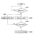
- FIG. 3 is a flowchart showing standby control processing executed by the pump controller 24.
- the standby control is executed when an activation operation by the operation member 46a is detected.
- the start-up operation is an operation for starting discharge of hydraulic oil from the main pump 10.
- the operation state determination unit 24c determines whether an activation operation has been performed.
- the operation state determination unit 24c determines whether an activation operation has been performed based on the operation position of the operation member 46a. For example, when an operation for increasing the capacity of the main pump 10 from 0 to a predetermined capacity is performed, the operation state determination unit 24c determines that an activation operation has been performed.
- the process proceeds to step S202.
- step S202 the accumulated pressure detection unit 48 detects the accumulated pressure Pacc of the accumulator 38.
- step S203 the accumulated pressure determination unit 24e determines whether or not the accumulated pressure Pacc is greater than the third set pressure.
- the third set pressure is not less than the first set pressure.
- the third set pressure may be the same as the first set pressure.
- step S204 the pump control unit 24a starts discharging from the main pump 10. Specifically, the pump control unit 24 a increases the capacities of the first hydraulic pump 12 and the second hydraulic pump 13 by controlling the first pump flow rate control unit 25 and the second pump flow rate control unit 26.
- step S203 when the accumulated pressure Pacc is equal to or lower than the third set pressure, the pump control unit 24a displays a standby display on the display device 47 in step S205.
- the standby display is a display indicating that standby control is being executed. That is, the standby display is a display for notifying the operator that the discharge from the main pump 10 is not started by the execution of the standby control.
- the pump control unit 24a determines that the accumulated pressure of the accumulator 38 is equal to the first accumulated pressure even if the operation member 46a performs the starting operation. Until the set pressure exceeds 3, the discharge of hydraulic oil from the main pump 10 is not started.
- the hydraulic drive system 1 according to the present embodiment has the following characteristics.
- the discharge pressure of the charge pump 28 when the hydraulic cylinder 14 is not operated, the discharge pressure of the charge pump 28 is reduced to a low pressure. For this reason, the loss of the power consumption in the charge pump 28 can be reduced. Further, when the pressure of the hydraulic oil flow path 15 between the main pump 10 and the check valves 44 and 45 is increased to the holding pressure, the hydraulic oil discharged from the charge pump 28 and the hydraulic oil stored in the accumulator 38 are used. The hydraulic oil can be supplemented to the hydraulic oil passage 15. For this reason, the charge pump 28 can be downsized as compared with the case where the hydraulic oil is replenished to the hydraulic oil flow path 15 only by the charge pump 28. Thereby, the loss of power consumption in the charge pump 28 can be further reduced.
- the third check valve 49 prevents the hydraulic oil accumulated in the accumulator 38 from flowing to the charge pump 28 when the charge pump 28 is stopped. Thereby, the fall of the accumulated pressure of the accumulator 38 can be suppressed.
- the discharge pressure control unit 24d changes the discharge pressure of the charge pump 28 from a low pressure to a normal pressure when the accumulated pressure of the accumulator 38 becomes equal to or lower than the first set pressure while the hydraulic cylinder 14 is not operated. Thereby, even if the hydraulic cylinder 14 is maintained in a non-operating state for a long time, a decrease in the accumulated pressure of the accumulator 38 can be suppressed. That is, it is possible to suppress the occurrence of aeration or cavitation in the first hydraulic pump 12 when the operation of the hydraulic cylinder 14 is started.
- the discharge of the hydraulic oil from the main pump 10 is not started until the accumulated pressure of the accumulator 38 becomes larger than the third set pressure. For this reason, it is possible to suppress the occurrence of aeration or cavitation in the first hydraulic pump 12. Further, the third set pressure is not less than the first set pressure. For this reason, discharge of the hydraulic oil from the main pump 10 can be started in a state where the required amount of hydraulic oil is accumulated in the accumulator 38.
- a standby display is displayed on the display device 47. Thereby, the operator can know that the main pump 10 does not start because the standby control is being executed.
- the operation state determination unit 24c determines that the hydraulic cylinder 14 is not operated when the operation member 46a is held at the neutral position for a predetermined time t0 or longer. Therefore, it is possible to prevent erroneous determination that the hydraulic cylinder 14 is not operated when the hydraulic cylinder 14 is not being operated, such as when the operating member 46a temporarily passes through the neutral position. Can do.
- FIG. 4 is a block diagram showing the configuration of the hydraulic drive system 2 according to the second embodiment of the present invention.
- a first pilot check valve 51 and a second pilot check valve 52 are used in place of the flow path switching valve 16 of the first embodiment.
- the first pilot check valve 51 is switched between a restricted state and an open state by a command signal from the pump controller 24.
- the first pilot check valve 51 allows the flow of hydraulic oil from the first pump flow path 33 to the first cylinder flow path 31, and allows the first pilot check valve 51 to flow from the first cylinder flow path 31 to the first pump flow path 33. Prohibit hydraulic fluid flow.
- the first pilot check valve 51 permits the flow of hydraulic oil from the first cylinder flow path 31 to the first pump flow path 33 in the open state.
- the second pilot check valve 52 is switched between a restricted state and an open state by a command signal from the pump controller 24.
- the second pilot check valve 52 permits the flow of hydraulic oil from the second pump flow path 34 to the second cylinder flow path 32 in the restricted state, and allows the second pilot check valve 52 to flow from the second cylinder flow path 32 to the second pump flow path 34.
- Prohibit hydraulic fluid flow The second pilot check valve 52 allows the flow of hydraulic oil from the second cylinder flow path 32 to the second pump flow path 34 in the open state.
- the pump controller 24 sets the first pilot check valve 51 to the restricted state and sets the second pilot check valve 52 to the open state. To do. Therefore, when the hydraulic pressure in the first pump flow path 33 exceeds the holding pressure in the first cylinder flow path 31, the first pilot check valve 51 is opened and the operation discharged from the first hydraulic pump 12 and the second hydraulic pump 13 is performed. Oil is supplied to the first chamber 14 c of the hydraulic cylinder 14 through the first pump flow path 33 and the first cylinder flow path 31. Further, the hydraulic oil is discharged from the second chamber 14 d of the hydraulic cylinder 14 and returned to the first hydraulic pump 12 through the second cylinder flow path 32 and the second pump flow path 34.
- the pump controller 24 sets the first pilot check valve 51 to the open state and sets the second pilot check valve 52 to the restricted state. To do. Therefore, when the hydraulic pressure of the second pump flow path 34 exceeds the holding pressure of the second cylinder flow path 32, the hydraulic oil discharged from the first hydraulic pump 12 becomes the second pump flow path 34 and the second cylinder flow path. 32 is supplied to the second chamber 14 d of the hydraulic cylinder 14. Further, the hydraulic oil is discharged from the first chamber 14 c of the hydraulic cylinder 14, returned to the first hydraulic pump 12 and the second hydraulic pump 13 through the first cylinder flow path 31 and the first pump flow path 33. .
- hydraulic drive system 2 Other configurations of the hydraulic drive system 2 are the same as those of the hydraulic drive system 1 of the first embodiment. Also, the hydraulic drive system 2 of the second embodiment has the same features as the hydraulic drive system 1 of the first embodiment.
- the pump flow control parts 25 and 26 control the discharge flow volume of the hydraulic pumps 12 and 13 by controlling the tilt angle of the hydraulic pumps 12 and 13.
- FIG. the discharge flow rates of the hydraulic pumps 12 and 13 may be controlled by controlling the rotational speeds of the hydraulic pumps 12 and 13.
- an electric motor 57 may be used as a drive source.
- an electric motor 57 is used instead of the engine 11.
- the hydraulic pumps 12 and 13 are fixed displacement hydraulic pumps.
- the pump controller 24 controls the rotational speed of the electric motor 57 so that the discharge flow rate of the hydraulic pumps 12 and 13 becomes a target flow rate corresponding to the operation amount of the operation member 46a.
- an electric motor 57 may be used as a drive source instead of the engine 11.
- the start-up operation in the standby control may be an operation for increasing the rotational speed of the hydraulic pumps 12 and 13 from 0 to a predetermined rotational speed.
- the discharge pressure reducing unit 39 is set to the closed state Pb when the command signal from the pump controller 24 is OFF. Further, the discharge pressure reducing unit 39 is set to the connection state Pa when the command signal from the pump controller 24 is ON. However, contrary to the above, the discharge pressure reducing unit 39 may be set to the connection state Pa by the urging force of the urging member 39a when the command signal from the pump controller 24 is OFF. When the command signal from the pump controller 24 is ON, the discharge pressure reducing unit 39 may be set to the closed state Pb by the solenoid thrust.
- the discharge pressure reducing unit is not limited to the bypass valve, but may be any device that can reduce the discharge pressure of the charge pump 28 more than the set pressure of the charge relief valve 42.
- the charge relief valve 42 may be used as the discharge pressure reducing unit.
- the relief pressure of the charge relief valve 42 can be switched between the first relief pressure and the second relief pressure.
- the first relief pressure corresponds to the normal pressure described above.
- the second relief pressure corresponds to the low pressure described above.
- the charge relief valve 42 reduces the discharge pressure of the charge pump 28 by switching the relief pressure from the first relief pressure to the second relief pressure based on a command signal from the pump controller 24.
- a one-way valve other than the check valve may be used.
- the display device 47 is not limited to a display device, and other display devices such as warning lights may be used.
- the determination of whether the hydraulic cylinder 14 is being operated or not is not limited to the operation of the operation member 46a, and may be determined by other methods. For example, it may be determined whether the hydraulic cylinder 14 is being operated or not being operated by detecting the operation of the hydraulic cylinder 14. However, in order to perform the above-described standby control, the operation state determination unit 24c preferably performs determination based on an operation of the operation member 46a.
Landscapes
- Engineering & Computer Science (AREA)
- General Engineering & Computer Science (AREA)
- Mining & Mineral Resources (AREA)
- Civil Engineering (AREA)
- Structural Engineering (AREA)
- Physics & Mathematics (AREA)
- Fluid Mechanics (AREA)
- Mechanical Engineering (AREA)
- Fluid-Pressure Circuits (AREA)
- Operation Control Of Excavators (AREA)
Description
図1は、本発明の第1実施形態に係る油圧駆動システム1の構成を示すブロック図である。油圧駆動システム1は、例えば油圧ショベル、ホイールローダー、ブルドーザなどの作業機械に搭載される。油圧駆動システム1は、エンジン11と、メインポンプ10と、油圧シリンダ14と、作動油流路15と、流路切換弁16と、エンジンコントローラ22と、ポンプコントローラ24とを有する。
油圧シリンダ14への作動油の流れの方向の切換は、第1実施形態の流路切換弁16に限らず、他の構成によって行われてもよい。図4は、本発明の第2実施形態に係る油圧駆動システム2の構成を示すブロック図である。油圧駆動システム2では、第1実施形態の流路切換弁16に替えて、第1パイロットチェック弁51と第2パイロットチェック弁52が用いられている。第1パイロットチェック弁51は、ポンプコントローラ24からの指令信号によって規制状態と開放状態とに切り換えられる。第1パイロットチェック弁51は、規制状態では、第1ポンプ流路33から第1シリンダ流路31への作動油の流れを許容し、第1シリンダ流路31から第1ポンプ流路33への作動油の流れを禁止する。第1パイロットチェック弁51は、開放状態では、第1シリンダ流路31から第1ポンプ流路33への作動油の流れを許容する。第2パイロットチェック弁52は、ポンプコントローラ24からの指令信号によって規制状態と開放状態とに切り換えられる。第2パイロットチェック弁52は、規制状態では、第2ポンプ流路34から第2シリンダ流路32への作動油の流れを許容し、第2シリンダ流路32から第2ポンプ流路34への作動油の流れを禁止する。第2パイロットチェック弁52は、開放状態では、第2シリンダ流路32から第2ポンプ流路34への作動油の流れを許容する。
10 メインポンプ
14 油圧シリンダ
15 作動油流路
19 チャージ回路
24a ポンプ制御部
24c 操作状態判定部
24d 吐出圧制御部
24e 蓄圧力判定部
28 チャージポンプ
35 チャージ流路
38 アキュムレータ
39 吐出圧低減部
44 第1チェック弁
45 第2チェック弁
46a 操作部材
47 表示装置
48 蓄圧力検出部
49 第3チェック弁
Claims (8)
- 作動油を吐出する第1油圧ポンプ及び第2油圧ポンプを有するメインポンプと、
前記メインポンプから吐出された作動油によって駆動される油圧シリンダと、
前記第1油圧ポンプと前記第2油圧ポンプとを前記油圧シリンダに接続し、前記第1油圧ポンプと前記油圧シリンダとの間で閉回路を構成する作動油流路と、
前記作動油流路において前記メインポンプと前記油圧シリンダとの間に配置され、前記メインポンプから前記油圧シリンダへの作動油の流れを許容し、前記油圧シリンダから前記メインポンプへの作動油の流れを禁止するチェック弁と、
前記作動油流路において前記メインポンプと前記チェック弁との間に接続されるチャージ流路と、前記チャージ流路に作動油を吐出するチャージポンプと、を有し、前記作動油流路の油圧が前記チャージ流路の油圧より小さくなったときに前記作動油流路へ作動油を補充するチャージ回路と、
前記油圧シリンダを操作するための操作部材と、
前記油圧シリンダが操作中であるのか非操作中であるのかを判定する操作状態判定部と、
前記チャージポンプの吐出圧を低減させる吐出圧低減部と、
前記油圧シリンダが非操作中であるときには、前記吐出圧低減部を制御して、前記チャージポンプの吐出圧を、前記油圧シリンダが操作中であるときの前記チャージポンプの吐出圧である通常圧力よりも低い低圧力に低減させる吐出圧制御部と、
前記チャージ流路に接続されるアキュムレータと、
前記アキュムレータと前記チャージポンプとの間に配置され、前記チャージポンプから前記アキュムレータへの作動油の流れを許容し、前記アキュムレータから前記チャージポンプへの作動油の流れを禁止する一方向弁と、
を備える油圧駆動システム。 - 前記アキュムレータの蓄圧力を検出する蓄圧力検出部と、
前記アキュムレータの蓄圧力が第1の設定圧以下であるか否かを判定する蓄圧力判定部と、
をさらに備え、
前記吐出圧制御部は、前記油圧シリンダの非操作中に、前記アキュムレータの蓄圧力が第1の設定圧以下になったときには、前記チャージポンプの吐出圧を前記低圧力から前記通常圧力に変更する、
請求項1に記載の油圧駆動システム。 - 前記蓄圧力判定部は、前記アキュムレータの蓄圧力が、前記第1の設定圧より大きい第2の設定圧以上であるか否かを判定し、
前記吐出圧制御部は、前記油圧シリンダの非操作中に、前記アキュムレータの蓄圧力が、前記第1の設定圧以下の圧力から、前記第2の設定圧以上の圧力に回復したときには、前記チャージポンプの吐出圧を前記通常圧力から前記低圧力に戻す、
請求項2に記載の油圧駆動システム。 - 前記操作部材の操作位置に基づいて前記メインポンプの吐出流量を制御するポンプ制御部をさらに備え、
前記操作状態判定部は、前記操作部材の操作位置に基づいて、前記油圧シリンダが操作中であるのか非操作中であるのかを判定し、
前記蓄圧力判定部は、前記アキュムレータの蓄圧力が第3の設定圧以下であるか否かを判定し、
前記アキュムレータの蓄圧力が第3の設定圧以下であるときに前記操作部材によって前記メインポンプからの作動油の吐出を開始させる操作が行われても、前記ポンプ制御部は、前記アキュムレータの蓄圧力が前記第3の設定圧より大きくなるまでは前記メインポンプからの作動油の吐出を開始させない待機制御を行う、
請求項2又は3に記載の油圧駆動システム。 - 前記第3の設定圧は、前記第1の設定圧以上の圧力である、
請求項4に記載の油圧駆動システム。 - 前記待機制御の実行中であることを表示する表示装置をさらに備える、
請求項4に記載の油圧駆動システム。 - 前記操作状態判定部は、前記操作部材が所定時間以上、中立位置に保持されているときに、前記油圧シリンダが非操作中であると判定する、
請求項1に記載の油圧駆動システム。 - 前記チャージ流路は、前記チャージポンプに接続される第1チャージ流路と、前記一方向弁を介して前記第1チャージ流路に接続される第2チャージ流路とを有し、
前記吐出圧低減部は、前記第1チャージ流路の油圧を低減させる、
請求項1に記載の油圧駆動システム。
Priority Applications (3)
| Application Number | Priority Date | Filing Date | Title |
|---|---|---|---|
| DE112012005015.0T DE112012005015B4 (de) | 2012-02-27 | 2012-09-11 | Hydraulisches Antriebssystem |
| CN201280052653.3A CN103890413B (zh) | 2012-02-27 | 2012-09-11 | 液压驱动系统 |
| US14/356,705 US9709076B2 (en) | 2012-02-27 | 2012-09-11 | Hydraulic drive system |
Applications Claiming Priority (2)
| Application Number | Priority Date | Filing Date | Title |
|---|---|---|---|
| JP2012-039787 | 2012-02-27 | ||
| JP2012039787A JP5956184B2 (ja) | 2012-02-27 | 2012-02-27 | 油圧駆動システム |
Publications (1)
| Publication Number | Publication Date |
|---|---|
| WO2013128690A1 true WO2013128690A1 (ja) | 2013-09-06 |
Family
ID=49081918
Family Applications (1)
| Application Number | Title | Priority Date | Filing Date |
|---|---|---|---|
| PCT/JP2012/073119 Ceased WO2013128690A1 (ja) | 2012-02-27 | 2012-09-11 | 油圧駆動システム |
Country Status (5)
| Country | Link |
|---|---|
| US (1) | US9709076B2 (ja) |
| JP (1) | JP5956184B2 (ja) |
| CN (1) | CN103890413B (ja) |
| DE (1) | DE112012005015B4 (ja) |
| WO (1) | WO2013128690A1 (ja) |
Cited By (1)
| Publication number | Priority date | Publication date | Assignee | Title |
|---|---|---|---|---|
| JP2020133804A (ja) * | 2019-02-21 | 2020-08-31 | 日立建機株式会社 | 建設機械 |
Families Citing this family (14)
| Publication number | Priority date | Publication date | Assignee | Title |
|---|---|---|---|---|
| JP6021144B2 (ja) * | 2012-07-17 | 2016-11-09 | 株式会社小松製作所 | 油圧駆動システム |
| KR102273523B1 (ko) * | 2014-03-06 | 2021-07-05 | 스미토모 겐키 가부시키가이샤 | 쇼벨 |
| JP6328548B2 (ja) | 2014-12-23 | 2018-05-23 | 日立建機株式会社 | 作業機械 |
| JP6539556B2 (ja) * | 2015-09-18 | 2019-07-03 | 株式会社神戸製鋼所 | 作業機械の油圧駆動装置 |
| WO2017162298A1 (en) * | 2016-03-24 | 2017-09-28 | Hydronit S.R.L. | Hydraulic system, smart power unit and operation method of the system |
| EP3263953B1 (de) * | 2016-06-28 | 2019-11-06 | Thomas Magnete GmbH | Hydrostatischer antrieb mit geschlossenem kreislauf und verfahren zum betrieb des antriebs |
| JP6654521B2 (ja) * | 2016-07-15 | 2020-02-26 | 日立建機株式会社 | 建設機械 |
| DE102016118853B3 (de) * | 2016-10-05 | 2017-10-26 | Hoerbiger Automatisierungstechnik Holding Gmbh | Elektrohydraulische Antriebseinheit |
| DE102017106693B3 (de) * | 2017-03-29 | 2018-05-30 | Voith Patent Gmbh | Vorrichtung zum Regeln einer hydraulischen Maschine |
| DE102017106700B3 (de) * | 2017-03-29 | 2018-05-17 | Voith Patent Gmbh | Vorrichtung zum Regeln einer hydraulischen Maschine |
| JP7182441B2 (ja) * | 2018-12-05 | 2022-12-02 | 日本電産トーソク株式会社 | 油圧制御装置 |
| JP7324370B2 (ja) * | 2020-06-17 | 2023-08-09 | 日立建機株式会社 | 建設機械 |
| EP4435271A4 (en) * | 2022-02-24 | 2025-12-17 | Hitachi Construction Mach Co | WORK MACHINE |
| CN116771827B (zh) * | 2023-06-25 | 2025-12-19 | 中国铁建重工集团股份有限公司 | 一种青贮机用行走控制液压系统及其控制方法 |
Citations (7)
| Publication number | Priority date | Publication date | Assignee | Title |
|---|---|---|---|---|
| JP2695001B2 (ja) * | 1989-04-25 | 1997-12-24 | カヤバ工業株式会社 | 油圧モータの一定速度制御回路 |
| JP2569841Y2 (ja) * | 1992-06-29 | 1998-04-28 | 株式会社タダノ | 油圧作業機の操作装置 |
| JP2973478B2 (ja) * | 1990-06-22 | 1999-11-08 | ダイキン工業株式会社 | 射出成形機並びに射出成形機における型締装置及び射出装置 |
| JPH11351007A (ja) * | 1998-06-10 | 1999-12-21 | Hitachi Constr Mach Co Ltd | 作業車両の原動機回転数制御装置および方法 |
| JP2005249198A (ja) * | 2004-03-05 | 2005-09-15 | Deere & Co | 作業器具用の閉回路エネルギ回収システム |
| JP2009079775A (ja) * | 2008-12-08 | 2009-04-16 | Sumitomo (Shi) Construction Machinery Manufacturing Co Ltd | 油圧閉回路の油圧シリンダ保持装置 |
| JP2012015272A (ja) * | 2010-06-30 | 2012-01-19 | Ulvac Japan Ltd | 処理装置及び搬送装置 |
Family Cites Families (8)
| Publication number | Priority date | Publication date | Assignee | Title |
|---|---|---|---|---|
| KR920010875B1 (ko) * | 1988-06-29 | 1992-12-19 | 히다찌 겐끼 가부시기가이샤 | 유압구동장치 |
| USH1977H1 (en) * | 1998-12-23 | 2001-08-07 | Caterpillar Inc. | Closed loop hydraulic system with variable charge pressure |
| JP3862256B2 (ja) * | 2000-05-19 | 2006-12-27 | 株式会社小松製作所 | 油圧駆動装置付きハイブリッド機械 |
| JP3923242B2 (ja) * | 2000-07-14 | 2007-05-30 | 株式会社小松製作所 | 油圧駆動機械のアクチュエータ制御装置 |
| US7234298B2 (en) | 2005-10-06 | 2007-06-26 | Caterpillar Inc | Hybrid hydraulic system and work machine using same |
| WO2007140947A1 (de) | 2006-06-02 | 2007-12-13 | Brueninghaus Hydromatik Gmbh | Hydrostatischer antrieb mit volumenstromausgleich |
| EP2252799B1 (en) * | 2008-02-12 | 2014-06-11 | Parker-Hannifin Corporation | Flow management system for hydraulic work machine |
| US8984873B2 (en) * | 2011-10-21 | 2015-03-24 | Caterpillar Inc. | Meterless hydraulic system having flow sharing and combining functionality |
-
2012
- 2012-02-27 JP JP2012039787A patent/JP5956184B2/ja not_active Expired - Fee Related
- 2012-09-11 CN CN201280052653.3A patent/CN103890413B/zh not_active Expired - Fee Related
- 2012-09-11 DE DE112012005015.0T patent/DE112012005015B4/de not_active Expired - Fee Related
- 2012-09-11 WO PCT/JP2012/073119 patent/WO2013128690A1/ja not_active Ceased
- 2012-09-11 US US14/356,705 patent/US9709076B2/en not_active Expired - Fee Related
Patent Citations (7)
| Publication number | Priority date | Publication date | Assignee | Title |
|---|---|---|---|---|
| JP2695001B2 (ja) * | 1989-04-25 | 1997-12-24 | カヤバ工業株式会社 | 油圧モータの一定速度制御回路 |
| JP2973478B2 (ja) * | 1990-06-22 | 1999-11-08 | ダイキン工業株式会社 | 射出成形機並びに射出成形機における型締装置及び射出装置 |
| JP2569841Y2 (ja) * | 1992-06-29 | 1998-04-28 | 株式会社タダノ | 油圧作業機の操作装置 |
| JPH11351007A (ja) * | 1998-06-10 | 1999-12-21 | Hitachi Constr Mach Co Ltd | 作業車両の原動機回転数制御装置および方法 |
| JP2005249198A (ja) * | 2004-03-05 | 2005-09-15 | Deere & Co | 作業器具用の閉回路エネルギ回収システム |
| JP2009079775A (ja) * | 2008-12-08 | 2009-04-16 | Sumitomo (Shi) Construction Machinery Manufacturing Co Ltd | 油圧閉回路の油圧シリンダ保持装置 |
| JP2012015272A (ja) * | 2010-06-30 | 2012-01-19 | Ulvac Japan Ltd | 処理装置及び搬送装置 |
Cited By (2)
| Publication number | Priority date | Publication date | Assignee | Title |
|---|---|---|---|---|
| JP2020133804A (ja) * | 2019-02-21 | 2020-08-31 | 日立建機株式会社 | 建設機械 |
| JP7146669B2 (ja) | 2019-02-21 | 2022-10-04 | 日立建機株式会社 | 建設機械 |
Also Published As
| Publication number | Publication date |
|---|---|
| US20140345265A1 (en) | 2014-11-27 |
| US9709076B2 (en) | 2017-07-18 |
| CN103890413A (zh) | 2014-06-25 |
| CN103890413B (zh) | 2016-04-20 |
| DE112012005015B4 (de) | 2017-02-09 |
| DE112012005015T5 (de) | 2014-08-28 |
| JP2013174325A (ja) | 2013-09-05 |
| JP5956184B2 (ja) | 2016-07-27 |
Similar Documents
| Publication | Publication Date | Title |
|---|---|---|
| JP5956184B2 (ja) | 油圧駆動システム | |
| KR101992510B1 (ko) | 건설 기계 | |
| JP5378061B2 (ja) | ハイブリッド建設機械の制御装置 | |
| JP5752526B2 (ja) | 油圧駆動システム | |
| KR101273086B1 (ko) | 하이브리드 건설 기계의 제어 장치 | |
| JP5956179B2 (ja) | 油圧駆動システム | |
| CN101981259B (zh) | 混合动力建筑机械的控制装置 | |
| US9695841B2 (en) | Hydraulic closed circuit system | |
| JP6021144B2 (ja) | 油圧駆動システム | |
| CN112334669B (zh) | 工程机械 | |
| JP2009275771A (ja) | 流体圧アクチュエータ制御回路 | |
| JP6091154B2 (ja) | 油圧駆動システム | |
| JP2011075045A (ja) | 油圧作業機械の油圧制御装置 | |
| JP2009275776A (ja) | 流体圧アクチュエータ制御回路 | |
| JP5265595B2 (ja) | ハイブリッド建設機械の制御装置 | |
| JP2013044398A (ja) | 油圧駆動システム | |
| JP2019135406A (ja) | エネルギ回生システム | |
| JP2013044399A (ja) | 油圧駆動システム | |
| JP4148884B2 (ja) | 建設機械のエンジンラグダウン抑制装置 | |
| JP2025156819A (ja) | 建設機械の油圧回路 | |
| JP7847487B2 (ja) | 液圧駆動装置 | |
| JP5403237B2 (ja) | 油圧駆動式作業車両 |
Legal Events
| Date | Code | Title | Description |
|---|---|---|---|
| WWE | Wipo information: entry into national phase |
Ref document number: 201280052653.3 Country of ref document: CN |
|
| 121 | Ep: the epo has been informed by wipo that ep was designated in this application |
Ref document number: 12870162 Country of ref document: EP Kind code of ref document: A1 |
|
| WWE | Wipo information: entry into national phase |
Ref document number: 112012005015 Country of ref document: DE Ref document number: 1120120050150 Country of ref document: DE |
|
| WWE | Wipo information: entry into national phase |
Ref document number: 14356705 Country of ref document: US |
|
| 122 | Ep: pct application non-entry in european phase |
Ref document number: 12870162 Country of ref document: EP Kind code of ref document: A1 |