WO2013128518A1 - Dispositif de transmission de courant, dispositif de réception de courant, système d'alimentation et dispositif électronique - Google Patents
Dispositif de transmission de courant, dispositif de réception de courant, système d'alimentation et dispositif électronique Download PDFInfo
- Publication number
- WO2013128518A1 WO2013128518A1 PCT/JP2012/007312 JP2012007312W WO2013128518A1 WO 2013128518 A1 WO2013128518 A1 WO 2013128518A1 JP 2012007312 W JP2012007312 W JP 2012007312W WO 2013128518 A1 WO2013128518 A1 WO 2013128518A1
- Authority
- WO
- WIPO (PCT)
- Prior art keywords
- power
- coil
- power transmission
- resonance
- power receiving
- Prior art date
Links
Images


Classifications
-
- H—ELECTRICITY
- H02—GENERATION; CONVERSION OR DISTRIBUTION OF ELECTRIC POWER
- H02J—CIRCUIT ARRANGEMENTS OR SYSTEMS FOR SUPPLYING OR DISTRIBUTING ELECTRIC POWER; SYSTEMS FOR STORING ELECTRIC ENERGY
- H02J50/00—Circuit arrangements or systems for wireless supply or distribution of electric power
- H02J50/40—Circuit arrangements or systems for wireless supply or distribution of electric power using two or more transmitting or receiving devices
- H02J50/402—Circuit arrangements or systems for wireless supply or distribution of electric power using two or more transmitting or receiving devices the two or more transmitting or the two or more receiving devices being integrated in the same unit, e.g. power mats with several coils or antennas with several sub-antennas
-
- H—ELECTRICITY
- H02—GENERATION; CONVERSION OR DISTRIBUTION OF ELECTRIC POWER
- H02J—CIRCUIT ARRANGEMENTS OR SYSTEMS FOR SUPPLYING OR DISTRIBUTING ELECTRIC POWER; SYSTEMS FOR STORING ELECTRIC ENERGY
- H02J50/00—Circuit arrangements or systems for wireless supply or distribution of electric power
- H02J50/10—Circuit arrangements or systems for wireless supply or distribution of electric power using inductive coupling
- H02J50/12—Circuit arrangements or systems for wireless supply or distribution of electric power using inductive coupling of the resonant type
-
- H—ELECTRICITY
- H01—ELECTRIC ELEMENTS
- H01F—MAGNETS; INDUCTANCES; TRANSFORMERS; SELECTION OF MATERIALS FOR THEIR MAGNETIC PROPERTIES
- H01F38/00—Adaptations of transformers or inductances for specific applications or functions
- H01F38/14—Inductive couplings
Definitions
- the present invention relates to a power transmission / reception system, and more specifically, to a system for supplying power to a power receiving device in a contactless manner without going through a power transmission line.
- Patent Document 1 discloses a configuration in which an electromagnetic wave propagates in an electromagnetic wave transmission sheet and an electromagnetic field leaking from the sheet is supplied to a power receiving device (in addition, JP 2007-281678 (Patent Document 2)).
- Patent Document 3 discloses a power transmission method using a microwave beam. For example, solar power generation is performed on a sanitary orbit, and the energy is transmitted to the ground with a microwave beam. Then, the microwave is reconverted into electric power by the ground power receiving system.
- Patent Document 4 there is a method of transmitting electric power from a power source side primary coil to a load side secondary coil by electromagnetic induction. This is often used to charge small household electronic devices such as shavers and electric toothbrushes.
- Patent Documents 5 and 6 have an advantage that the power transmission distance can be extended as compared with the electromagnetic induction method. However, even the method of Patent Document 5 has a problem that the power transmission efficiency is extremely lowered when the power transmission distance exceeds about twice or three times the diameter of the power transmission coil.
- an object of the present invention is to provide a power transmission device, a power reception device, and a power supply system that can maintain a relatively high power transmission efficiency even when a power transmission distance is long in wireless power feeding.
- the power transmission device of the present invention is A power transmission coil unit that has a plurality of resonance coils arranged so as to form a one-dimensional periodic structure, and transmits power to the power reception device by magnetic field resonance with the power reception device; A power supply unit that supplies power to the power transmission coil unit, The power transmission coil section is used as a transmission path for electromagnetic propagation waves, and a standing wave of electromagnetic propagation waves is generated in the power transmission coil section.
- the power receiving device of the present invention is A plurality of resonance coils arranged so as to form a one-dimensional periodic structure, and a power receiving coil unit that receives power from the power transmission device by magnetic field resonance with the power transmission device; A power receiving unit that receives power from the power receiving coil unit, The power receiving coil portion serves as an electromagnetic propagation wave transmission path, and a standing wave of the electromagnetic propagation wave is generated in the power receiving coil portion due to magnetic field resonance with the power transmission device.
- a power supply system includes the power transmission device and the power reception device.
- the figure which shows the equivalent circuit of the circuit of FIG. The equivalent circuit diagram of one unit of a periodic structure.
- FIG. The figure which shows the state in which the standing wave has arisen in three resonance coils.
- FIG. The figure of the experimental result which shows the difference in the power transmission efficiency at the time of changing the distance from a floor surface.
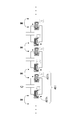
- FIG. 1 is a configuration diagram of a power supply system according to the first embodiment of the present invention.
- the power supply system 100 includes a power transmission device 200 and a power reception device 300.
- the front-rear direction is determined for each of the power transmission device 200 and the power reception device 300.
- the power transmission device 200 and the power reception device 300 are arranged at a distance, and the power reception device 300 side of the power transmission device 200 is the front side.
- the side farther from the power receiving device 300 in the power transmitting device 200 is the rear side.
- the power transmission device 200 side is defined as the front side.
- the side farther from the power transmission device 200 in the power reception device 300 is the rear side.
- the power transmission device 200 includes a power transmission coil unit 210 and a power feeding unit 280.
- the power transmission coil unit 210 includes a front coil unit 220, a rear coil unit 230, and a power feeding coil 240.
- the pre-stage coil unit 220 is composed of one resonance coil. This resonance coil is referred to as a front coil 221.
- the front coil 221 is a spring-type coil, and is disposed on the front side (that is, the power reception device 300 side) of the power supply coil 240.
- the rear coil unit 230 has two spring type coils, and is arranged behind the power supply coil 240 (that is, on the side far from the power receiving device 300).
- the first rear coil 231 and the second rear coil 232 are from the side closer to the feeding coil 240. That is, the feeding coil 240 is disposed so as to be sandwiched between the front coil 221 and the first rear coil 231.
- the front coil 221, the first rear coil 231 and the second rear coil 232 are arranged at a constant pitch.
- a structure configured by periodically arranging a plurality of resonance coils is referred to as a “coil periodic structure”.
- the axis of the front coil 221, the axis of the feeding coil 240, the axis of the first rear coil 231, and the axis of the second rear coil 232 are substantially coaxial, but the axes intersect each other.
- An angle may be attached as follows.
- the front coil 221, the first rear coil 231, and the second rear coil 232 are arranged at a substantially constant pitch. The arrangement pitch may be slightly deviated within the propagation range.
- the pre-stage coil 221, the first post-stage coil 231 and the second post-stage coil 232 have the same coil characteristics and the same resonance (resonance) frequency. That is, the resonance coils having different characteristics are not arranged, but a plurality of resonance coils having the same characteristics are arranged.
- the resonance frequency may be shifted within a range in which the electromagnetic wave can propagate.
- the resonance frequency varies due to manufacturing errors. The smaller the error is, the more desirable electromagnetic propagation characteristics can be obtained.
- the resonance frequency variation is about 10 kHz or less than the resonance frequency variation is about 100 kHz. Propagation characteristics can be obtained.
- Japanese Patent Application Laid-Open No. 2011-147271 only includes a plurality of resonance coils having different resonance frequencies so as to be compatible with a plurality of frequencies.
- Japanese Unexamined Patent Application Publication No. 2011-147271 discloses that a plurality of resonance coils are arranged as a transmission line as in the present embodiment, and that the transmission efficiency is improved by controlling the near magnetic field distribution. Not disclosed.
- the power feeding unit 280 includes a power source 281, a power application unit 282, and a frequency control unit 283.
- the power application unit 282 applies power to the feeding coil 240.
- the power application unit 282 causes an alternating current having a controlled frequency to flow through the feeding coil 240.
- the frequency control unit 283 controls the frequency of the current applied to the power feeding coil 240 by, for example, switching.
- the frequency control unit 283 may be provided with an adjusting unit for the user to manually adjust the frequency.
- the configuration of power reception device 300 is basically the same as that of power transmission device 200, and includes power reception coil unit 310 and power reception unit 380.
- the power receiving coil unit 310 includes a front coil unit 320, a rear coil unit 330, and a power receiving coil 340.
- the pre-stage coil unit 320 is composed of one resonance coil, and this is referred to as a pre-stage coil 321.
- the rear coil unit 330 includes a first rear coil 331 and a second rear coil 332.
- the power receiving coil 340 is disposed between the front coil 321 and the first rear coil 331.
- the power receiving unit 380 supplies the received power to the load 900 after rectifying the power received by the power receiving coil 340 or performing voltage conversion.
- FIG. 2 is a configuration diagram of a power supply system 10 as a background technique using an electromagnetic resonance phenomenon.
- a front coil 30 for power transmission is disposed in front of the power feeding coil 20, but no coil is disposed in the rear stage of the power feeding coil 20.
- the pre-stage coil 50 is arranged at the front stage of the power receiving coil 40, but the coil is not arranged at the rear stage of the power receiving coil 40. 2 is different from the configuration of the first embodiment in whether the power transmission coil unit 210 and the power reception coil unit 310 have a plurality of resonance coils.
- the power transmission efficiency is compared between the present embodiment of FIG. 1 and the background art of FIG.
- FIG. 3 is a result of measuring the power transmission efficiency by changing the distance between the first embodiment (FIG. 1) and the background art (FIG. 2).
- the horizontal axis is the distance [m]
- the vertical axis is the logarithm of the power transmission efficiency [%].
- the diameter of each coil was 20 cm, the height was 10 cm, and the number of turns was 19.
- the resonance frequency of each coil was adjusted to be around 8.64 MHz by cutting the copper wire at the coil end so that the variation was within 10 kHz. That is, the frequency of the power supplied to the power supply coils 20 and 240 was adjusted to 8.64 MHz.
- the power transmission efficiency of the first embodiment is increased when the distance exceeds 50 cm.
- the power transmission efficiency decreases as the distance increases.
- the power transmission efficiency does not decrease even when the distance increases, and is slightly increased depending on the viewpoint. Looks like. Since the diameter of one coil is 20 cm, it can be said that the present embodiment is more effective when the power transmission distance exceeds 2 to 3 times the coil diameter. Thus, according to this embodiment, it turns out that there exists an effect which can lengthen power transmission distance, keeping power transmission efficiency high.
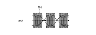
- electromagnetic propagation wave As a result, for example, when a plurality of resonance coils 401 are arranged as shown in FIG. 4, it is possible to determine what mode of electromagnetic wave is generated there.
- this wave is referred to as “electromagnetic propagation wave”. That is, the present inventors expressed the relationship between the frequency (f) and the wave number (k) of the electromagnetic propagation wave that can occur in the periodic structure of the coil as a dispersion curve as shown in FIG. d represents one cycle length of the periodic structure, and is, for example, a center-to-center distance between adjacent coils. Therefore, “wave number (k) ⁇ one cycle length (d)” which is the horizontal axis of the graph of FIG. 5 means a phase change per cycle length.
- the coil periodic structure can be treated as an electromagnetic wave propagation region, that is, a transmission line when this structure is regarded as a metamaterial. .
- the inventors have come up with a configuration in which an arbitrary electric field distribution is generated in the periodic structure (transmission line).
- a method of obtaining a dispersion curve of electromagnetic propagation waves generated there by treating a resonance coil periodic structure in which resonance coils 401 are periodically arranged as a metamaterial will be described.
- the resonance coil 401 a spring type coil is taken as an example.
- An arrangement structure in which a plurality of coils 401 are arranged coaxially as in the power transmission coil unit 210 in FIG. 1 is replaced with the equivalent circuit in FIG. 6.
- M is a mutual inductance between adjacent coils 401.
- the capacitance component C is explicitly extracted, and the resistance component is ignored.
- the black circle in a figure shows the polarity of winding.
- FIG. 7 the circuit of FIG. 6 can be equivalently converted as shown in FIG. In FIG. 7, one coil 401 is depicted as being divided into two coil components 401h and 401h. Therefore, the inductance of one coil component 401h is L / 2.
- circuit of FIG. 7 can perform equivalent conversion as shown in FIG. 8 while paying attention to the polarity of the coil.
- one unit (one unit) of this periodic structure can be redrawn in the equivalent circuit of FIG.
- one unit (one unit) of the periodic structure can be expressed by the T matrix as follows.
- d be the periodic interval (distance between the centers of the coils) of this periodic structure.
- the wave number in the traveling direction of the electromagnetic propagation wave traveling through the metamaterial is k x .
- k x ⁇ d represents the phase of the wave for each period, and the following equation is established.
- the dispersion curve when the coil periodic structure is a metamaterial has been obtained.
- an electromagnetic field is transmitted to the adjacent resonance coil, and the coil periodic structure becomes a transmission line for electromagnetic propagation waves.
- the transmission line loss is small, the electromagnetic field distribution on the transmission line is a so-called standing wave distribution.
- a standing wave can be generated in a transmission line with a coil periodic structure. Furthermore, if a wave that satisfies the resonance condition of the coil periodic structure is generated, the number of antinodes of the standing wave (electromagnetic propagation wave) can be controlled.
- the number of coils is n
- the coil interval is d
- phase X is 0 ⁇ X ⁇ ⁇
- m 0, 1,... N ⁇ 1.
- the frequency of the feed power for example, the frequency of the alternating current
- a standing wave of electromagnetic propagation waves can be generated in the coil periodic structure (see, for example, FIG. 4).
- the number of nodes is 0 and the number of bellies is 1.
- magnetic resonance generated in the power transmission coil unit 210 and the power reception coil unit 310 can be controlled using such a phenomenon.
- the power transmission coil unit 210 and the power reception coil unit 310 are configured by three coils.
- stable standing waves are generated in the three coils (221, 231, 232) of the power transmission coil unit 210, and when a magnetic field loop is illustrated, the front coil 221 and the power receiving coil of the power transmission coil unit 210 as illustrated in FIG.
- the optimum magnetic field resonance state differs from the example of FIG. Of course.
- a stable standing wave can be created by creating a resonance state in the power transmission coil unit 210 (or the power reception coil unit 310) constituted by a plurality of resonance coils, and the power transmission coil unit 210 can thereby generate a power reception coil unit 310. There will be no change in the efficiency of power transmission.
- FIGS. 15 and 16 are a measurement system explanatory diagram and measurement results showing this.
- the distance between the coil periodic structure (the power transmission coil unit 210 and the power reception coil unit 310) and the floor surface 800 is set to 20 cm or 60 cm.
- FIG. 16 shows the results of measuring the power transmission efficiency in the above two cases. From FIG. 16, it can be seen that when the distance from the floor 800 is set to 20 cm, the power transmission efficiency is improved at a certain distance from the floor 800, rather than from 60 cm.
- the floor surface 800 and the coil periodic structure may be skillfully used to improve power transmission efficiency.
- a material that reflects or shields electromagnetic waves such as a metal plate, may be skillfully used to improve power transmission efficiency.
- the power supply coil 240 (power reception coil 340) is disposed immediately behind the front coil 221 (321).
- the power feeding coil 240 power receiving coil 340
- the power feeding coil 240 may be disposed anywhere between the plurality of resonance coils arranged.
- a feeding coil (or a receiving coil) may be arranged between the second and third from the front (right) while seven or more coils are arranged.
- the front coil part (220) is composed of two resonance coils 221 and 222
- the rear coil part is composed of the third and subsequent coils.
- the impedance of the resonance coil may be variable. By making the impedance of the resonance coil variable, the dispersion curve can be shifted as shown in FIG.
- the dielectric constant or magnetic permeability of the coil core may be controlled, or a variable capacitance may be added to the resonance coil to change the capacitance value of the variable capacitance.
- an impedance control unit 284 is provided in the power feeding unit. As described above, if the coil impedance is variable on the power transmission coil unit 210 side, a desired resonance state can be created in the power transmission coil unit 210 with respect to the fixed frequency.
- the impedances of all the coils constituting the power transmission coil unit may be changed at the same time, or the impedances of the individual coils may be individually changed and adjusted. Good.
- the impedances of all the coils may be changed at the same time, or the impedances of the individual coils may be individually changed and adjusted.
- a spring type coil is exemplified as the resonance coil.
- the resonance coil for example, a planar spiral coil shown in FIG. 20A may be used.
- the planar spiral coil 501 has an advantage that it can be mounted on a printed circuit board. That is, one spiral coil 501 may be mounted on the front surface or the back surface of the printed board. Alternatively, planar spiral coils may be mounted on both sides of the printed board.
- the planar spiral coil 501 of FIG. 20A is mounted on the front side of the printed board.
- the coil 502 of FIG. 20B is mounted on the back surface of the printed board.
- 20B is a perspective view of the coil 501 mounted on the back surface of the printed circuit board from the front surface side.
- a continuous spiral shape can be formed as double-sided mounting by conducting conductor connection between the front side coil 501 and the back side coil 502 at the junction point 503.
- various types of spiral conductors can be mounted on the multilayer substrate by using the spiral conductors of the respective layers and the conductors connecting the layers.
- 20A and 20B exemplify a spiral coil having a rectangular shape and each side of the rectangle having a linear shape, it goes without saying that it may be a curved spiral.
- the spiral coil may be mounted on the high dielectric substrate.
- a spiral coil may be mounted on the magnetic material.
- the space between the power transmission device and the power reception device is generally air, but water, seawater, soil, or a wall may be provided between the power transmission device and the power reception device.
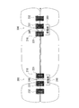
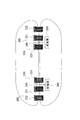
- a plurality of power transmission coil units may be two-dimensionally arranged. Further, for example, as shown in FIG. 21, a plurality of power transmission coil sections (or power reception coil sections) arranged two-dimensionally are sandwiched between two rigid boards 611 and 612, and the power transmission coil section (or power reception coil section) ) May be rigid so that it does not bend. Alternatively, the power transmission coil unit or the power reception coil unit may be flexibly bent by sandwiching the resonance coil between two sheets having flexibility.
- the term “periodic structure” is used to express that the power transmission coil unit (or the power receiving coil unit) is composed of a periodic structure including a plurality of resonance coils.
- the periodic structure should not be construed to be limited to an array structure with a strictly constant pitch.
- the period may not be strictly constant, and it is allowed that the arrangement pitch of the resonance coils is deviated within a range in which the power transmission coil unit (or power reception coil unit) can be handled as a metamaterial in view of the whole purpose of the present invention.
- the arrangement pitch of the resonance coils is designed in consideration of manufacturing restrictions, so that the arrangement period is allowed to deviate depending on the manufacturing conditions.
- Examples of the load that receives power supply from the power receiving device include various applied products such as various sensors, household appliances, portable terminals, and electric vehicles.
- one power transmission coil part was equipped with one coil periodic structure.
- one power receiving coil portion has one coil periodic structure. This is because the frequency of magnetic field resonance between the power transmission coil unit and the power reception coil unit is one, but both the power transmission coil unit and the power reception coil unit may have a plurality of coil periodic structures. For example, when a plurality of coil periodic structures are provided in one power transmission coil unit (or power receiving coil unit), a second coil periodic structure may be provided inside the first coil periodic structure. According to such a configuration, power can be transmitted at one frequency, and a signal can be transmitted at another frequency.
- DESCRIPTION OF SYMBOLS 100 Electric power supply system, 200 ... Power transmission apparatus, 210 ... Power transmission coil part, 220 ... Pre-stage coil part, 221 ... Pre-stage coil part, 230 ... Rear stage coil part, 231 ... 1st latter stage coil, 232 ... 2nd latter stage coil, 240 ... feeding coil, 280 ... feeding part, 281 ... power supply, 282 ... power application part, 283 ... frequency control part, 284: Impedance control unit, 300 ... Power receiving device, 310 ... Power receiving coil unit, 320 ... Pre-coil unit, 321 ... Pre-coil, 330 ... Post-coil unit, 331 ... First rear coil, 332 ...
Abstract
L'objet de l'invention est de résoudre le problème consistant à fournir, dans une alimentation électrique sans fil, un système d'alimentation électrique pouvant maintenir une efficacité de transmission de courant relativement élevée même lorsqu'une distance de transmission de courant est grande. Une unité bobine de transmission de courant (210) présente une pluralité de bobines de résonance (221) agencées de manière à former une structure périodique. Les bobines de résonance (221) forment une ligne de transmission pour une onde électromagnétique, et une onde stationnaire d'une onde à propagation électromagnétique se produit dans l'unité bobine de transmission de courant (210). De même, une unité bobine de réception de courant (310) présente une pluralité de bobines de résonance (321) agencées de manière à former une structure périodique. L'efficacité de transmission de courant est maintenue relativement élevée, même si la distance entre un dispositif de transmission de courant (200) et un dispositif de réception de courant (300) dépasse le double.
Applications Claiming Priority (2)
| Application Number | Priority Date | Filing Date | Title |
|---|---|---|---|
| JP2012-043772 | 2012-02-29 | ||
| JP2012043772 | 2012-02-29 |
Publications (1)
| Publication Number | Publication Date |
|---|---|
| WO2013128518A1 true WO2013128518A1 (fr) | 2013-09-06 |
Family
ID=49081783
Family Applications (1)
| Application Number | Title | Priority Date | Filing Date |
|---|---|---|---|
| PCT/JP2012/007312 WO2013128518A1 (fr) | 2012-02-29 | 2012-11-14 | Dispositif de transmission de courant, dispositif de réception de courant, système d'alimentation et dispositif électronique |
Country Status (2)
| Country | Link |
|---|---|
| JP (1) | JPWO2013128518A1 (fr) |
| WO (1) | WO2013128518A1 (fr) |
Cited By (1)
| Publication number | Priority date | Publication date | Assignee | Title |
|---|---|---|---|---|
| CN104953723A (zh) * | 2015-07-02 | 2015-09-30 | 中国科学院电工研究所 | 一种用于无线电能传输的装置 |
Citations (4)
| Publication number | Priority date | Publication date | Assignee | Title |
|---|---|---|---|---|
| JP2010130878A (ja) * | 2008-12-01 | 2010-06-10 | Toyota Industries Corp | 非接触電力伝送装置 |
| JP2011147271A (ja) * | 2010-01-14 | 2011-07-28 | Sony Corp | 給電装置、受電装置、およびワイヤレス給電システム |
| JP2011151989A (ja) * | 2010-01-22 | 2011-08-04 | Sony Corp | ワイヤレス給電装置およびワイヤレス給電システム |
| JP2011160634A (ja) * | 2010-02-04 | 2011-08-18 | Casio Computer Co Ltd | 電力伝送システム及び送電装置 |
-
2012
- 2012-11-14 WO PCT/JP2012/007312 patent/WO2013128518A1/fr active Application Filing
- 2012-11-14 JP JP2014501839A patent/JPWO2013128518A1/ja active Pending
Patent Citations (4)
| Publication number | Priority date | Publication date | Assignee | Title |
|---|---|---|---|---|
| JP2010130878A (ja) * | 2008-12-01 | 2010-06-10 | Toyota Industries Corp | 非接触電力伝送装置 |
| JP2011147271A (ja) * | 2010-01-14 | 2011-07-28 | Sony Corp | 給電装置、受電装置、およびワイヤレス給電システム |
| JP2011151989A (ja) * | 2010-01-22 | 2011-08-04 | Sony Corp | ワイヤレス給電装置およびワイヤレス給電システム |
| JP2011160634A (ja) * | 2010-02-04 | 2011-08-18 | Casio Computer Co Ltd | 電力伝送システム及び送電装置 |
Cited By (1)
| Publication number | Priority date | Publication date | Assignee | Title |
|---|---|---|---|---|
| CN104953723A (zh) * | 2015-07-02 | 2015-09-30 | 中国科学院电工研究所 | 一种用于无线电能传输的装置 |
Also Published As
| Publication number | Publication date |
|---|---|
| JPWO2013128518A1 (ja) | 2015-07-30 |
Similar Documents
| Publication | Publication Date | Title |
|---|---|---|
| US10158256B2 (en) | Contactless connector system tolerant of position displacement between transmitter coil and receiver coil and having high transmission efficiency | |
| US10957480B2 (en) | Large area power transmitter for wireless power transfer | |
| US9565794B2 (en) | Wireless power transmission system, power transmitting device, and power receiving device | |
| JP6467919B2 (ja) | 電力伝送装置及び電力伝送方法 | |
| JP2012182981A (ja) | エネルギーを無線で交換するシステムおよび方法 | |
| KR20120087568A (ko) | 무선 전력 전송 장치 및 방법 | |
| JP5981202B2 (ja) | 電力伝送システム | |
| US9887681B2 (en) | Power transmission system, transmission apparatus, receiving apparatus, and power transmission method | |
| CN107148710B (zh) | 使用堆叠谐振器的无线功率传输 | |
| CN106816297B (zh) | 无线电力传输装置、供电装置以及受电装置 | |
| JP6270219B2 (ja) | 電力供給装置 | |
| KR101140338B1 (ko) | 무선 전력 전송용 공진 코일 구조 | |
| KR101222137B1 (ko) | 자기공진유도 방식 지향성 무선 전력 전송 장치 | |
| JP2013099090A (ja) | 電磁波伝搬装置および電力伝送システム | |
| WO2013128518A1 (fr) | Dispositif de transmission de courant, dispositif de réception de courant, système d'alimentation et dispositif électronique | |
| JP2016076645A (ja) | 平面コイル | |
| JP5981203B2 (ja) | 電力伝送システム | |
| WO2013108325A1 (fr) | Système d'alimentation en énergie | |
| WO2018051936A1 (fr) | Dispositif d'alimentation électrique sans fil et procédé d'alimentation électrique sans fil | |
| WO2014030440A1 (fr) | Dispositif d'alimentation électrique | |
| Shi et al. | Parallel strips coupled split ring resonators for a desktop wireless charging system overcoming irregular route restrictions | |
| JP6760806B2 (ja) | 無線給電装置 | |
| JP2016059146A (ja) | 海水中給電システム | |
| JP5461277B2 (ja) | アンテナ装置、送電装置、受電装置および非接触電力伝送システム | |
| WO2013108324A1 (fr) | Système d'alimentation en énergie |
Legal Events
| Date | Code | Title | Description |
|---|---|---|---|
| 121 | Ep: the epo has been informed by wipo that ep was designated in this application |
Ref document number: 12870166 Country of ref document: EP Kind code of ref document: A1 |
|
| ENP | Entry into the national phase |
Ref document number: 2014501839 Country of ref document: JP Kind code of ref document: A |
|
| NENP | Non-entry into the national phase |
Ref country code: DE |
|
| 122 | Ep: pct application non-entry in european phase |
Ref document number: 12870166 Country of ref document: EP Kind code of ref document: A1 |