WO2013108325A1 - Système d'alimentation en énergie - Google Patents
Système d'alimentation en énergie Download PDFInfo
- Publication number
- WO2013108325A1 WO2013108325A1 PCT/JP2012/007394 JP2012007394W WO2013108325A1 WO 2013108325 A1 WO2013108325 A1 WO 2013108325A1 JP 2012007394 W JP2012007394 W JP 2012007394W WO 2013108325 A1 WO2013108325 A1 WO 2013108325A1
- Authority
- WO
- WIPO (PCT)
- Prior art keywords
- power
- coil
- power supply
- vibration
- unit
- Prior art date
Links
- 230000005540 biological transmission Effects 0.000 claims abstract description 87
- 230000005672 electromagnetic field Effects 0.000 claims abstract description 40
- 230000000737 periodic effect Effects 0.000 claims abstract description 38
- 230000008859 change Effects 0.000 claims abstract description 6
- 230000000644 propagated effect Effects 0.000 claims abstract description 6
- 230000003187 abdominal effect Effects 0.000 claims description 32
- 230000002238 attenuated effect Effects 0.000 claims description 7
- 230000009471 action Effects 0.000 claims description 4
- 230000010355 oscillation Effects 0.000 abstract 6
- 230000000694 effects Effects 0.000 abstract 1
- 230000002889 sympathetic effect Effects 0.000 abstract 1
- 238000009826 distribution Methods 0.000 description 18
- 239000006185 dispersion Substances 0.000 description 16
- 230000008878 coupling Effects 0.000 description 9
- 238000010168 coupling process Methods 0.000 description 9
- 238000005859 coupling reaction Methods 0.000 description 9
- 238000000034 method Methods 0.000 description 9
- 210000001015 abdomen Anatomy 0.000 description 7
- 230000005684 electric field Effects 0.000 description 7
- 239000004020 conductor Substances 0.000 description 6
- 238000010586 diagram Methods 0.000 description 6
- 230000007423 decrease Effects 0.000 description 5
- 238000011160 research Methods 0.000 description 5
- 238000005516 engineering process Methods 0.000 description 3
- 238000011156 evaluation Methods 0.000 description 3
- 230000004907 flux Effects 0.000 description 3
- 238000000926 separation method Methods 0.000 description 3
- 239000000758 substrate Substances 0.000 description 3
- 235000008694 Humulus lupulus Nutrition 0.000 description 2
- 238000004891 communication Methods 0.000 description 2
- 238000004519 manufacturing process Methods 0.000 description 2
- 230000004048 modification Effects 0.000 description 2
- 238000012986 modification Methods 0.000 description 2
- 238000004804 winding Methods 0.000 description 2
- 238000004458 analytical method Methods 0.000 description 1
- 230000008901 benefit Effects 0.000 description 1
- 239000003990 capacitor Substances 0.000 description 1
- 239000012141 concentrate Substances 0.000 description 1
- 239000000696 magnetic material Substances 0.000 description 1
- 230000007257 malfunction Effects 0.000 description 1
- 239000011159 matrix material Substances 0.000 description 1
- 238000005259 measurement Methods 0.000 description 1
- 230000005404 monopole Effects 0.000 description 1
- 230000035699 permeability Effects 0.000 description 1
- 238000010248 power generation Methods 0.000 description 1
- 239000013535 sea water Substances 0.000 description 1
- 238000005549 size reduction Methods 0.000 description 1
- 239000002689 soil Substances 0.000 description 1
- 239000002699 waste material Substances 0.000 description 1
- XLYOFNOQVPJJNP-UHFFFAOYSA-N water Substances O XLYOFNOQVPJJNP-UHFFFAOYSA-N 0.000 description 1
Images


Classifications
-
- H—ELECTRICITY
- H01—ELECTRIC ELEMENTS
- H01F—MAGNETS; INDUCTANCES; TRANSFORMERS; SELECTION OF MATERIALS FOR THEIR MAGNETIC PROPERTIES
- H01F38/00—Adaptations of transformers or inductances for specific applications or functions
- H01F38/14—Inductive couplings
-
- H—ELECTRICITY
- H02—GENERATION; CONVERSION OR DISTRIBUTION OF ELECTRIC POWER
- H02J—CIRCUIT ARRANGEMENTS OR SYSTEMS FOR SUPPLYING OR DISTRIBUTING ELECTRIC POWER; SYSTEMS FOR STORING ELECTRIC ENERGY
- H02J50/00—Circuit arrangements or systems for wireless supply or distribution of electric power
- H02J50/10—Circuit arrangements or systems for wireless supply or distribution of electric power using inductive coupling
- H02J50/12—Circuit arrangements or systems for wireless supply or distribution of electric power using inductive coupling of the resonant type
-
- H—ELECTRICITY
- H02—GENERATION; CONVERSION OR DISTRIBUTION OF ELECTRIC POWER
- H02J—CIRCUIT ARRANGEMENTS OR SYSTEMS FOR SUPPLYING OR DISTRIBUTING ELECTRIC POWER; SYSTEMS FOR STORING ELECTRIC ENERGY
- H02J50/00—Circuit arrangements or systems for wireless supply or distribution of electric power
- H02J50/40—Circuit arrangements or systems for wireless supply or distribution of electric power using two or more transmitting or receiving devices
- H02J50/402—Circuit arrangements or systems for wireless supply or distribution of electric power using two or more transmitting or receiving devices the two or more transmitting or the two or more receiving devices being integrated in the same unit, e.g. power mats with several coils or antennas with several sub-antennas
-
- H—ELECTRICITY
- H02—GENERATION; CONVERSION OR DISTRIBUTION OF ELECTRIC POWER
- H02J—CIRCUIT ARRANGEMENTS OR SYSTEMS FOR SUPPLYING OR DISTRIBUTING ELECTRIC POWER; SYSTEMS FOR STORING ELECTRIC ENERGY
- H02J50/00—Circuit arrangements or systems for wireless supply or distribution of electric power
- H02J50/90—Circuit arrangements or systems for wireless supply or distribution of electric power involving detection or optimisation of position, e.g. alignment
-
- H—ELECTRICITY
- H04—ELECTRIC COMMUNICATION TECHNIQUE
- H04B—TRANSMISSION
- H04B5/00—Near-field transmission systems, e.g. inductive or capacitive transmission systems
- H04B5/20—Near-field transmission systems, e.g. inductive or capacitive transmission systems characterised by the transmission technique; characterised by the transmission medium
- H04B5/24—Inductive coupling
-
- H—ELECTRICITY
- H04—ELECTRIC COMMUNICATION TECHNIQUE
- H04B—TRANSMISSION
- H04B5/00—Near-field transmission systems, e.g. inductive or capacitive transmission systems
- H04B5/70—Near-field transmission systems, e.g. inductive or capacitive transmission systems specially adapted for specific purposes
- H04B5/79—Near-field transmission systems, e.g. inductive or capacitive transmission systems specially adapted for specific purposes for data transfer in combination with power transfer
Definitions
- the present invention relates to a power supply system, and more specifically, to a system that supplies power to a power receiving device without contact with a power transmission line.
- the present invention relates to a power supply system that can selectively and efficiently supply power to a position of a desired power receiving apparatus in a state where the power transmitting apparatus and the power receiving apparatus are separated by a medium distance that is equal to or less than the wavelength of a transmission power wave.
- Japanese Patent Laid-Open No. 2008-66841 discloses a configuration in which an electromagnetic wave propagates in an electromagnetic wave transmission sheet and an electromagnetic field leaking from the sheet is supplied to a power receiving device (in addition, Japanese Patent Laid-Open No. 2007-281678). Issue gazette).
- Japanese Patent Application Laid-Open No. 2008-259392 discloses a power transmission method using a microwave beam. For example, solar power generation is performed on a sanitary orbit, and the energy is transmitted to the ground with a microwave beam. Then, the microwave is reconverted into electric power by the ground power receiving system.
- Kawahara is arranged in an area with some extent as shown in Fig. 27. Power is supplied to a plurality of electronic devices.
- the electronic device here includes, for example, a power transmission sheet, and the power transmission sheet can be used to supply power to a small electronic device.
- a plurality of coils are arranged in a plane on the wall and floor of the room. And it utilizes that the coils which adjoin in the direction orthogonal to a central axis also resonate. In other words, if power is supplied to one of the coils, the electric power hops to the adjacent coil. Electric power is propagated to adjacent coils, and electromagnetic fields are leaked from the coils into the room. Then, power can be supplied to a plurality of electronic devices arranged in a large area called a room. Thereby, it can be expected that operations such as wiring of the power supply line, charging, battery replacement and the like are unnecessary.
- JP 2008-66841 A JP 2007-281678 Japanese Patent Laid-Open No. 7-322534 US7825543B2 JP 2008-259392 A
- an object of the present invention is to provide a power supply system capable of selectively and efficiently supplying power to a desired power receiving device position in wireless power feeding.
- the power supply system of the present invention includes: A plurality of resonators are arranged in a one-dimensional or two-dimensional periodic structure, and power is propagated to the next resonator by resonance action, and electromagnetic fields are leaked to the surrounding area to transmit power wirelessly.
- a power transmission unit that performs A power supply unit that supplies power to one or more of the resonators of the power transmission unit;
- a vibration pattern setting unit that sets a vibration pattern of an electromagnetic field configured by repetition of a part that becomes an antinode of vibration and an electromagnetic field and a part that does not exist and becomes a node of vibration, and
- Each of the resonators can change its impedance to at least two states of open and short, and the impedance of the resonator at a position corresponding to a vibration node is opened.
- the power feeding unit feeds the coil corresponding to the antinode of vibration so that the amplitude is gradually attenuated while oscillating as the distance from the center is about the resonance body at the position facing the power receiving device to be fed.
- a plurality of resonators are arranged so as to form a one-dimensional or two-dimensional periodic structure, and power is propagated to an adjacent resonator by a resonance action,
- a power transmission unit that performs wireless power transmission by leaking an electromagnetic field; and
- a power supply unit that supplies power to one or a plurality of the resonators of the power transmission unit,
- the power transmission unit is configured to vibrate so as to form an electromagnetic field vibration pattern composed of a repetition of a part that becomes an antinode of vibration due to an electromagnetic field and a part that does not exist and becomes a node of vibration.
- the power feeding unit feeds the coil corresponding to the antinode of vibration so that the amplitude is gradually attenuated while oscillating as the distance from the center is about the resonance body at the position facing the power receiving device to be fed. It is characterized by performing.
- FIG. 5 is an equivalent circuit diagram of the circuit of FIG.
- FIG. 6 is an equivalent circuit diagram of a circuit in which a plurality of coils are arranged at a constant pitch.
- the equivalent circuit diagram of one unit of a periodic structure The figure which shows an example which arranged nine coils. The figure which shows the state which all the coils are vibrating with the same phase. The figure which shows the state which all the coils are vibrating with the reverse phase. The figure which shows a dispersion
- FIG. 10 is a diagram showing the relationship between the frequency and the vibration state of each coil in the fourth embodiment.
- FIG. 20 is a diagram showing another example of a vibration pattern in the fifth embodiment.
- FIG. 20 is a diagram showing another example of a vibration pattern in the fifth embodiment.
- FIGS. 1A and 1B An example of a power feeding system 100 that the present invention desires to realize is shown in FIGS. 1A and 1B.
- the power receiving device 120 is separated from the power transmission unit 110 by a certain distance.
- the separation distance is about several centimeters to several meters. That is, this separation distance is not such a close distance that magnetic coupling can be established between the primary coil and the secondary coil that are closely opposed to each other.
- the distance is not about a wavelength of an electromagnetic wave that allows the directional antenna to exhibit directivity, or a far away distance.
- the separation distance assumed by the present invention is a distance shorter than the wavelength of the electromagnetic wave.
- the power transmission unit 110 includes a plurality of resonators 111, and the plurality of resonators 111 are arranged two-dimensionally (planarly).
- a conductor coil is typical.
- the resonator is a spiral coil 112.
- the resonator 111 may be, for example, a dielectric resonator other than a conductor coil.
- the type of the dielectric resonator is not limited, and various shapes such as a rectangular shape and a cylindrical shape can be adopted.
- the power transmission unit 110 may be, for example, a room wall or a floor itself. That is, as an example, a plurality of resonators 111 (coils 112) are embedded in one surface of a floor or wall of a room and used as the power transmission unit 110.
- the power feeding unit 130 supplies power to one or more resonators 111.
- the resonator 111 is the coil 112
- an alternating current may be passed through the coil 112.
- an oscillating magnetic field may be applied to the coil 112.
- the electromagnetic field distribution of the leaked electromagnetic wave forms a peak only at a desired position of the power receiving device 120 and the intensity becomes weak at other places.
- FIG. 1A it is assumed that there are three power receiving apparatuses 120 to which power is supplied. In this case, it is desired that the electromagnetic field intensity peaks at the three power receiving devices 120 and the intensity decreases at other places. Or, in some cases, it is desirable to supply power to only one of the three power receiving devices 120, for example. For example, when it is desired to supply power only to the middle power receiving apparatus 120 as shown in FIG. 1B, the electric field is concentrated only on this one power receiving apparatus, and the electric field strength is weakened at other places.
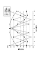
- electromagnetic propagation wave As a result, for example, when a coil as a resonator is arranged as shown in FIG. 2, it is possible to determine what mode wave is generated by electromagnetic field hopping.
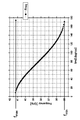
- this wave is referred to as “electromagnetic propagation wave”. That is, the present inventors expressed the relationship between the frequency (f) and the wave number (k) of the electromagnetic propagation wave that can occur in the periodic structure of the coil as a dispersion curve as shown in FIG. d represents one cycle length of the periodic structure, and is, for example, a center-to-center distance between adjacent coils. Therefore, “wave number (k) ⁇ one cycle length (d)” on the horizontal axis of the graph of FIG. 3 means a phase change per cycle length.
- the dispersion curve in FIG. 3 shows that at a frequency f between f max and f min , the coil periodic structure can be treated as an electromagnetic wave propagation region, that is, a transmission line when this structure is regarded as a metamaterial. .
- the inventors have come up with a configuration in which an arbitrary electric field distribution is generated in the periodic structure (transmission line).
- Theory for obtaining the dispersion curve of electromagnetic wave propagation A method of obtaining a dispersion curve of electromagnetic propagation waves generated there by treating a resonator periodic structure in which resonators are periodically arranged as a metamaterial will be described.
- a spring type coil is taken as an example of the resonator.
- the resonance frequency fres, inductance L, capacitance C, and resistance R of a single coil are obtained, and further, the coupling constant M when two coils are arranged adjacent to each other is obtained.
- the characteristics of a single coil can be calculated from the frequency dependence of impedance Z by providing an input port 113 in the coil 112 as shown in FIG. That is, the circuit in FIG. 4 is replaced with the equivalent circuit in FIG. 5 in which the capacitance component and the resistance component are extracted. Then, the frequency dependence of Re (Z) and Im (Z) is obtained by electromagnetic field analysis or actual measurement.
- the resonance frequency f res is obtained from the point where Im (Z). Using two points in the vicinity of the resonance frequency f res, the inductance L and the capacitance C are obtained by the following equations. Two points in the vicinity of the resonance frequency f res are defined as (f 1 , Im (Z 1 )) and (f 2 , Im (Z 2 )).
- the splitting of the resonance frequency is confirmed using a model in which two coils 112 and 112 are arranged.
- power is supplied to one coil 112 from the input port 113, and the power is hopped to the other coil 112, and the power of the other coil 112 is obtained from the output port 114.
- the splitting can be performed by changing the internal resistance of the input / output ports 113 and 114.
- the resonance frequency f res is split into a frequency f a and a frequency f b .
- the coupling constant k can be calculated from the two divided frequencies f a and f b by the following equation.
- the mutual inductance M is obtained from the coupling constant k and the inductance L by the following relational expression.
- FIG. 7 when a plurality of coils 112 are arranged horizontally at a constant pitch, an equivalent circuit thereof can be drawn as shown in FIG.
- one coil 112 is depicted as being divided into two coil components 112h and 112h. Therefore, the inductance of one coil component 112h is L / 2. In this case, the resistance R is ignored.
- one unit (one unit) of this periodic structure can be redrawn in the equivalent circuit of FIG.
- one unit (one unit) of the periodic structure can be expressed by the T matrix as follows.
- d be the periodic interval (distance between the centers of the coils) of this periodic structure.
- the periodic structure is a metamaterial
- the wave number in the traveling direction of the electromagnetic propagation wave traveling through the metamaterial is k x .
- k x ⁇ d represents the phase of the wave for each period, and the following equation is established.
- the frequency band (f min ⁇ f ⁇ f max ) of the wave (electromagnetic field) generated in the metamaterial is obtained. That is, the dispersion curve of FIG. 3 can be drawn in the frequency band (f min ⁇ f ⁇ f max ).
- the dispersion curve when the coil periodic structure is a metamaterial has been obtained.
- the electromagnetic field is transmitted by hopping, and the coil periodic structure becomes a transmission line for electromagnetic propagation waves.
- the transmission line loss is small, the electromagnetic field distribution on the transmission line is a so-called standing wave distribution.
- a coil periodic structure can be used as a transmission line, and a standing wave can be generated in the transmission line. Furthermore, if a wave that satisfies the resonance condition of the coil periodic structure is generated, the number of antinodes of the standing wave (electromagnetic propagation wave) can be controlled.
- the number of coils is n
- the coil interval is d
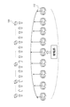
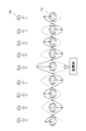
- FIG. 9 shows a case where nine coils are arranged in a line at a constant pitch and the middle coil is fed.
- the middle fifth coil is a coil that receives power from the power feeding section.
- the number of bellies is 9 (the number of nodes is 8).
- the coil periodic structure is used as the power transmission unit 110, and the number of beams (locations where the electromagnetic field strength is increased) can be controlled at a position at a short distance from the power transmission unit 110.
- the number of bellies there are two ways to control the number of bellies.
- One is a variable frequency system. For example, a pair of a phase and a frequency where a standing wave exists is obtained from the dispersion curve of FIG. 12A, and a frequency at which the antinode is a desired number as shown in FIG.
- the other is a variable impedance system. That is, the frequency is fixed, the impedance of the coil (resonator) is made variable, and the dispersion curve is shifted as shown in FIG.
- FIG. 14 shows a power supply system using a variable frequency system.
- the power supply system 200 includes a power transmission unit 210, a power feeding unit 220, and a power receiving device 280.
- the power transmission unit 210 is configured by a coil as a resonator, and a plurality of coils 211 are arranged so as to form a periodic structure.
- the power transmission unit 210 may be configured by a one-dimensional array of coils, but it goes without saying that the coils may be arranged in a plane to form a two-dimensional periodic structure, which may be used as a power transmission unit.
- the power feeding unit 220 includes a power source 221, a power application unit 222, a frequency control unit 223, and an adjustment unit 224.
- the power application unit 222 can selectively apply power to one or a plurality of coils 211 of the power transmission unit 210.
- an input port (not shown) may be provided in the winding of the coil 211, and current may be supplied from the input port (not shown).
- a switch (not shown) is provided in the wiring for wiring from the power application unit 222 toward each coil 211 and for selecting a coil for supplying power (current).
- an alternating magnetic field may be applied to the center of the coil by magnetic coupling.
- the frequency control unit 223 controls the frequency of the current or magnetic field applied to the coil by, for example, switching.
- Adjustment means 224 is attached to the frequency control unit 223 so that the user can manually adjust the frequency.
- the adjusting means 224 may be a user interface having input items that allow the user to directly operate the frequency value. Alternatively, the user may select the power receiving device 280 that is desired to be supplied with power.
- the adjusting unit 224 automatically calculates the frequency of the power to be applied based on the number and position of the selected power receiving devices 280, and outputs the calculated frequency value to the frequency control unit 223. Also good.
- electric power is applied to the coil 211 at a frequency adjusted so that a number of standing waves corresponding to the number and position of the power receiving devices 280 can be generated. That is, the frequency of the supplied power is controlled by frequency control by the frequency control unit 223.
- the coil to which power is applied is appropriately selected according to the shape of the standing wave. Again, the frequency is selected from the range of frequencies where the power transmission unit 210 can be handled as a metamaterial, that is, between f max and f min, and further adjusted to a phase X that satisfies the resonance state Is done.
- the antinodes of electromagnetic propagation waves can be created according to the desired position of the power receiving device 280, and the electromagnetic field leaking at other locations becomes weak. Thus, power can be efficiently supplied to the power receiving device 280.
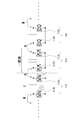
- FIG. 15 shows a power supply system using a variable impedance system.
- the power supply system 300 includes a power transmission unit 310, an impedance control unit 330, a power feeding unit 320, and a power receiving device 280.
- the power transmission unit 310 includes a coil 311 as a resonator, and a plurality of coils 311 are arranged so as to form a periodic structure.
- a variable impedance 312 is added to the coil 311.
- the impedance control unit 330 controls the impedance value of the variable impedance 312 of the coil 311. Specifically, the imaginary impedance part, that is, the reactance value is controlled.
- the impedance control unit 330 may be configured to individually control the impedance value of each coil, but here, the impedance values of the variable impedances 312 of all the coils 311 are the same at the same time so as to shift the dispersion curve. It shall be changed as follows.
- Adjustment means 331 is attached to the impedance control unit 330 so that the user can manually control the impedance of the coil 311.
- the adjusting means 331 may be a user interface having input items that allow the user to directly operate the impedance value.
- the user may select the power receiving device 280 that is desired to be supplied with power. Then, the adjusting unit 331 may obtain the impedance value of the coil based on the number and position of the selected power receiving devices 280, and output the calculated impedance value to the impedance control unit 330.
- the power feeding unit 320 includes a power source 321, a power application unit 322, and a frequency control unit 323.
- the configuration of the power application unit 322 is the same as that of the first embodiment.
- the frequency control unit 323 is provided to fix the frequency to a predetermined value between f max and f min so that the power transmission unit 310 can be handled as a metamaterial.
- FIG. 16 shows a power supply system using a variable impedance system.
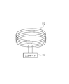
- the basic configuration of the third embodiment is the same as that of the second embodiment, but differs from the second embodiment in that the impedance of the coil 411 is changed by controlling the core (coil core) 412. .
- the winding of the coil 412 is disposed so as to surround the core (coil core) 412.
- the impedance control unit 430 moves the coil core 412 relative to the coil 411. This changes the magnetic flux or electrical flux through the coil 411, thereby changing the impedance of the coil 411.
- the configuration of the power feeding unit 320 is the same as that of the second embodiment, and power having a frequency fixed at a predetermined value between f max and f min is applied to the selected coil 411.
- the electromagnetic propagation wave generated in the power transmission unit is made to be a standing wave, and desired power reception is performed by controlling the number of antinodes of the standing wave. Efficient power can be supplied only to the device.
- the inventors of the present invention have developed the idea through intensive research, and have searched for a method for concentrating the beam more efficiently on a desired power receiving apparatus.
- a plane wave source near-field focusing plate
- an observation plane focal plane
- Electromagnetic propagation occurs from a plane wave source having such an electric field distribution.
- a plane wave source is referred to as a near-field focusing wave source.
- a specific observation plane focal plane
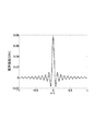
- an electric field distribution that is remarkably large only near the center as shown in FIG. 19 and rapidly attenuates in other regions is obtained.
- the observed electric field distribution is expressed as follows.
- the power supply system described with reference to FIG. 1 can also be realized.
- the electromagnetic field distribution of the plane wave source is expressed as shown in Equation 7, it is not limited to this shape. If the electromagnetic field distribution gradually attenuates from the center while vibrating, as shown in FIG. It is considered that an electromagnetic field distribution in which energy is concentrated at the center can be obtained.
- the problem to be solved here is how to realize the plane wave source (near-field focusing wave source). Therefore, the plane wave source (near-field focusing wave source) is realized by using the resonator periodic structure as a metamaterial.
- the power supply system 500 includes a power transmission unit 510, an impedance control unit 530, a power feeding unit 520, an adjustment unit 540, and a power receiving device 280.
- the power transmission unit 510 includes a coil 511 serving as a resonance body, and a variable resistor 512 is added to the coil 511. The resistance value of the variable resistor 512 of the coil 511 is individually controlled by the impedance control unit 530.
- the adjusting means 540 adjusts selection of a coil to be fed, frequency value of the feeding power, and impedance of each coil according to a user operation.
- the power feeding unit 520 applies a frequency (f max >f> f min ) within a range in which the resonant body periodic structure of the power transmission unit 510 can be handled as a metamaterial.
- the impedance control unit 530 sets the impedance of each coil so that the amplitude of the standing wave (electromagnetic propagation wave) is attenuated with the coil to which power is supplied as the center of vibration, and away from the center. For example, the transmission loss in the power transmission unit is increased to some extent, for example, the Q value is set to 100 or less.
- the adjusting means 540 adjusts the frequency and impedance so that the electromagnetic propagation wave becomes a standing wave and is attenuated as it moves away from the center. Then, as compared with the standing wave pattern shown in FIG. 12B, as shown in FIG. 21, a standing wave (electromagnetic hopping wave) whose amplitude attenuates as the distance from the center is obtained. In this way, the near-field focusing wave source can be realized by using the resonator periodic structure. As a result, it is possible to realize a power supply system that efficiently concentrates power feeding only on a desired power receiving device 280.
- a power supply system 600 includes a power transmission unit 610, an impedance control unit 630, a power feeding unit 620, an adjustment unit 640, a vibration pattern setting unit 650, and a power receiving device 280.
- the power transmission unit 610 includes a coil 611 serving as a resonance body, and a variable resistor 612 is incorporated in each coil 611.
- the variable resistor 612 can be switched between three states: open (high impedance), short (low impedance), and ON (intermediate impedance).
- Vibration pattern setting unit 650 sets an electromagnetic field vibration pattern in power transmission unit 610.
- the vibration pattern is composed of a repetition of a portion where an electromagnetic field exists and becomes an antinode of vibration, and a portion where no electromagnetic field exists and becomes a node of vibration. That is, the vibration pattern setting unit 650 sets a pattern of which coil 611 is a vibration antinode and which coil 611 is a vibration node.
- the coil 611 of the power transmission unit 610 is divided into a unit 613A composed of three coils and a single coil portion 613N sandwiched between the units 613A and 613A. Is shown.
- a unit 613A composed of three coils is used as a vibration antinode, and a coil (613N) between them is used as a vibration node.
- FIG. 23A and FIG. 23B are other examples of vibration patterns.
- FIG. 23A shows an example in which the coil 611 of the power transmission unit 610 is divided into a unit 614 composed of five coils and two coils sandwiched between the unit 614 and the unit 614.
- the unit that becomes the antinode of vibration may be composed of two coils, or may be composed of four or five or more coils. There may be two or more coils serving as vibration nodes.
- the coil that becomes the antinode of the vibration and the coil that becomes the node of the vibration may be alternately arranged one by one.
- a coil unit that becomes a vibration antinode is referred to as an abdominal unit
- a coil unit that becomes a vibration node is referred to as a node unit.
- the abdominal unit may be composed of one coil
- the node unit may be composed of one coil.
- the power application unit 622 of the power supply unit 620 supplies power to the abdominal unit 613A that is the antinode of vibration. At this time, the power application unit 622 does not supply power to the node unit 613N that becomes a node of vibration. Further, power is supplied so that adjacent abdominal units 613A are in opposite phases. Further, the magnitude of power can be controlled for each coil 611 to be fed.
- the impedance control unit 630 controls the resistance value of the variable resistor 612 of each coil 611.
- the resistance value of the coil 611 that is included in the same unit 613A as the coil 611 that receives power supply but does not receive power supply is set to low (short).
- the resistance value of the coil 611 of the node unit 613N, which is a node of vibration is set high (open).
- the adjusting means 640 adjusts the vibration pattern setting, the selection of the coil to be fed, the frequency value of the feeding power, and the impedance of each coil according to the user's operation.
- the vibration pattern setting unit 650 divides the coil of the power transmission unit 610 into an abdominal unit 613A and a node unit 613N. At this time, one abdominal unit 613A is placed directly under the power receiving device 280 to be fed. This abdominal unit 613A is the center of the near focusing wave source.
- the impedance control unit 630 turns on the impedance by using any one of the coils 611 in the abdominal unit 613A, preferably the middle coil 611 as a power feeding coil. Further, the resistance value of the coil 611 on both sides of the coil to be supplied with power is shorted (low). Further, the resistance value of the coil 611 of the node unit 613N is opened (high).
- the power supply unit 622 supplies power to the power supply coil.
- the abdomen unit 613A immediately below the power receiving device 280 becomes the center of vibration, and the power supplied to each abdomen unit is adjusted so that the amplitude of vibration decreases as the distance from the center decreases.
- the frequency of the power to be supplied is adjusted so that a standing wave is generated in one abdominal unit.
- a standing wave is generated by three coils.
- the three coils constituting one abdominal unit may be in phase (the number of nodes is zero).
- the abdominal unit 613A adjacent to each other is set in reverse phase. Thereby, the pattern of the near focusing wave source can be realized.
- FIG. 24 A sixth embodiment will be described. Although the basic configuration of the sixth embodiment is the same as that of the fifth embodiment, there is a difference in that only the abdominal unit is disposed and no resonator (coil) is disposed in the node portion and a gap is formed. As shown in FIG. 24, in the power supply system 700 of the sixth embodiment, only the coil that becomes the abdominal unit 713A is arranged in the power transmission unit 710, and a predetermined gap is provided between the adjacent abdominal unit. . The gap interval is designed so that electromagnetic hopping does not occur between the coils that sandwich the gap. And this gap becomes a wave node.
- the part that becomes the antinode and the part that becomes the node of the vibration are defined by the arrangement of the coils. Therefore, the vibration pattern setting unit 650 for setting the vibration pattern one by one is not necessary, and the coil arrangement structure is preset and stored as a vibration pattern in the adjusting means 740. In addition, a coil (power supply coil) to which power is applied by the power application unit 722 is also fixed in advance.
- an impedance control unit for controlling the impedance of each coil is basically unnecessary.
- an impedance control unit may be provided.
- the power supply unit 622 supplies power to the power supply coil.
- the abdomen unit 713A immediately below the power receiving device 280 becomes the center of vibration, and the power supplied to each abdomen unit is adjusted so that the amplitude of vibration decreases as the distance from the center decreases.
- electromagnetic hopping does not occur between adjacent abdominal units, and the amplitude and phase can be arbitrarily controlled by the power supplied to each abdominal unit 713A. it can.
- the dielectric constant or permeability of the coil core may be controlled, or a variable capacitance may be added to the coil to change the capacitance value of the variable capacitance.
- a spring type coil is exemplified as the resonator.
- a planar spiral coil shown in FIG. 26A may be used as the resonator.
- the planar spiral coil 201 has an advantage that it can be mounted on a conventional printed circuit board. That is, one spiral coil 201 may be mounted on the front surface or the back surface of the printed board. Alternatively, planar spiral coils may be mounted on both sides of the printed board.
- the planar spiral coil 201 of FIG. 26A is mounted on the front side of the printed board.
- the coil 202 in FIG. 26B is mounted on the back surface of the printed board.
- 26B is a perspective view of the coil 202 mounted on the back surface of the printed circuit board from the front surface side.
- a continuous spiral shape can be formed as double-sided mounting by conducting conductor connection between the front side coil 201 and the back side coil 202 at the junction 203.
- various types of spiral conductors can be mounted on the multilayer substrate by using the spiral conductors of the respective layers and the conductors connecting the layers.
- FIGS. 26A and 26B a spiral coil having a rectangular shape and each side of the rectangle being linear is illustrated, but it goes without saying that it may be a curved spiral.
- the spiral coil may be mounted on the high dielectric substrate.
- a spiral coil may be mounted on the magnetic material.
- the structure of the resonator is not limited to a coil, and may be, for example, a dielectric resonator, or a dipole antenna structure or a monopole antenna structure.
- the space between the power transmission unit and the power reception device is generally air, but water, seawater, soil, or a wall may be provided between the power transmission unit and the power reception device.
- the power transmission unit may be provided with rigidity so that the power transmission unit is not bent by sandwiching the resonance body (coil) of the power transmission unit between two rigid substrates.
- the power transmission unit may be bent flexibly by sandwiching the resonator (coil) of the power transmission unit between two sheets having flexibility.
- the vibration center of the near-focusing wave source is expressed as a coil that is located immediately below the power receiving device. This is because the power transmission unit is provided on the ceiling or side wall. In consideration of the case, the coil is located at a position facing the power receiving device to be fed. More precisely, the coil located at the foot of the perpendicular line from the power receiving device to be fed to the power transmission unit is used as the vibration center of the nearby focusing wave source.
- the term “periodic structure” is used, and the power transmission unit is expressed as a periodic structure including a plurality of resonators.
- the periodic structure should not be construed to be limited to an array structure with a strictly constant pitch. It does not have to be strictly a constant cycle, and it is allowed that the arrangement pitch of the resonators deviates within a range in which the power transmission unit can be handled as a metamaterial in view of the entire purpose of the present invention. Further, in the case of an actual product, the arrangement pitch of the resonators is designed in consideration of manufacturing restrictions, so that the arrangement period is allowed to deviate depending on the manufacturing conditions.
- DESCRIPTION OF SYMBOLS 100 ... Feed system, 110 ... Power transmission part, 111 ... Resonator, 112 ... Coil, 112h ... Coil component, 113 ... Input port, 114 ... Output port, 120 ..Power receiving device, 130 ... Power supply unit, 200 ... Power supply system, 201 ... Coil (front side coil), 202 ... Coil (back side coil), 203 ... Junction point, 210 ... Power transmission unit, 211 ... Coil, 220 ... Power feeding unit, 221 ... Power supply, 222 ... Power application unit, 223 ... Frequency control unit, 224 ... Adjustment means, 280 ..Power receiving device, 300 ... Power supply system, 310 ...
- Power transmission unit 311 ... Coil, 312 ... Variable impedance, 320 ... Power feeding unit, 321 ... Power source, 322 ... Power application unit, 323 ... Frequency control unit, 330 ... Impedance control unit, 331 ... Adjustment means, 410 ... Power transmission unit, 411 ... Coil, 412 ... Coil, 412 ... Coil core, 430 ... Impedance control unit, 500 ... Power supply system, 510 ... Power transmission unit, 511 ... Coil, 512 ... Variable resistance, 520 ... Feeding unit, 530 ..Impedance control unit, 540 ... Adjustment means, 600 ... Power supply system, 610 ... Power transmission unit, 611 ...
- Coil 612 ... Variable resistance, 613A ... Unit (abdominal unit) , 613N ... Node unit, 614 ... Unit, 620 ... Power feeding unit, 622 ... Power application unit, 630 ... Impedance control unit, 640 ... Adjustment means, 650 ... Vibration Pattern setting section.
Landscapes
- Engineering & Computer Science (AREA)
- Power Engineering (AREA)
- Computer Networks & Wireless Communication (AREA)
- Signal Processing (AREA)
- Electric Propulsion And Braking For Vehicles (AREA)
- Charge And Discharge Circuits For Batteries Or The Like (AREA)
Abstract
Le problème traité par la présente invention vise à proposer un système d'alimentation en énergie qui, lors d'une alimentation en énergie sans fil, peut efficacement fournir de l'énergie de manière sélective à la position d'un dispositif de réception de puissance souhaitée. Dans une unité de transmission d'énergie (610), une pluralité de corps de résonance (11) est disposée de manière à former une structure périodique 1D ou 2D, et l'énergie est transmise, au moyen d'une action de résonance sympathique, à des corps de résonance voisines (611). Une unité de réglage de motif d'oscillation (650) définit le motif d'oscillation d'un champ électromagnétique configuré à partir de la répétition d'une partie sur laquelle le champ électromagnétique est présent, ce qui est un anti-nœud d'oscillation, et d'une partie sur laquelle le champ électromagnétique n'est pas présent, ce qui est un nœud d'oscillation. Chaque corps de résonance (611) peut modifier son impédance entre au moins les deux états qui sont l'état ouvert et court et son impédance des corps de résonance (611) à des positions correspondant aux nœuds d'oscillation, et il est amené à être ouvert. Une unité d'alimentation en énergie (620) fournit du courant à des bobines (613a) correspondant à l'anti-nœud d'oscillation centré sur le corps de résonance à une position correspondant au dispositif de réception d'énergie (280) qui est le sujet d'alimentation en énergie, et l' amplitude de l'alimentation en énergie, tout en oscillant, s'atténue progressivement en fonction de la distance la séparant du centre.
Applications Claiming Priority (2)
| Application Number | Priority Date | Filing Date | Title |
|---|---|---|---|
| JP2012006929 | 2012-01-17 | ||
| JP2012-006929 | 2012-01-17 |
Publications (1)
| Publication Number | Publication Date |
|---|---|
| WO2013108325A1 true WO2013108325A1 (fr) | 2013-07-25 |
Family
ID=48798783
Family Applications (1)
| Application Number | Title | Priority Date | Filing Date |
|---|---|---|---|
| PCT/JP2012/007394 WO2013108325A1 (fr) | 2012-01-17 | 2012-11-16 | Système d'alimentation en énergie |
Country Status (2)
| Country | Link |
|---|---|
| JP (1) | JPWO2013108325A1 (fr) |
| WO (1) | WO2013108325A1 (fr) |
Cited By (3)
| Publication number | Priority date | Publication date | Assignee | Title |
|---|---|---|---|---|
| JP2015035935A (ja) * | 2013-08-09 | 2015-02-19 | 積水化学工業株式会社 | 給電システム、給電方法および建築部材 |
| WO2018229494A1 (fr) * | 2017-06-16 | 2018-12-20 | Metaboards Limited | Contrôle d'ondes magnéto-inductives |
| WO2020128520A1 (fr) * | 2018-12-20 | 2020-06-25 | Metaboards Limited | Localisation de charge |
Citations (3)
| Publication number | Priority date | Publication date | Assignee | Title |
|---|---|---|---|---|
| WO2008032746A1 (fr) * | 2006-09-12 | 2008-03-20 | The University Of Tokyo | Feuille d'alimentation électrique et circuit de connexion électrique |
| JP2010508008A (ja) * | 2006-10-26 | 2010-03-11 | コーニンクレッカ フィリップス エレクトロニクス エヌ ヴィ | 床の敷物及び誘導電力システム |
| JP2012075304A (ja) * | 2010-08-30 | 2012-04-12 | Univ Of Tokyo | 無線電力伝送装置 |
-
2012
- 2012-11-16 JP JP2013554095A patent/JPWO2013108325A1/ja active Pending
- 2012-11-16 WO PCT/JP2012/007394 patent/WO2013108325A1/fr active Application Filing
Patent Citations (3)
| Publication number | Priority date | Publication date | Assignee | Title |
|---|---|---|---|---|
| WO2008032746A1 (fr) * | 2006-09-12 | 2008-03-20 | The University Of Tokyo | Feuille d'alimentation électrique et circuit de connexion électrique |
| JP2010508008A (ja) * | 2006-10-26 | 2010-03-11 | コーニンクレッカ フィリップス エレクトロニクス エヌ ヴィ | 床の敷物及び誘導電力システム |
| JP2012075304A (ja) * | 2010-08-30 | 2012-04-12 | Univ Of Tokyo | 無線電力伝送装置 |
Cited By (4)
| Publication number | Priority date | Publication date | Assignee | Title |
|---|---|---|---|---|
| JP2015035935A (ja) * | 2013-08-09 | 2015-02-19 | 積水化学工業株式会社 | 給電システム、給電方法および建築部材 |
| WO2018229494A1 (fr) * | 2017-06-16 | 2018-12-20 | Metaboards Limited | Contrôle d'ondes magnéto-inductives |
| WO2020128520A1 (fr) * | 2018-12-20 | 2020-06-25 | Metaboards Limited | Localisation de charge |
| CN113196676A (zh) * | 2018-12-20 | 2021-07-30 | 元板有限公司 | 负载本地化 |
Also Published As
| Publication number | Publication date |
|---|---|
| JPWO2013108325A1 (ja) | 2015-05-11 |
Similar Documents
| Publication | Publication Date | Title |
|---|---|---|
| JP5698626B2 (ja) | ワイヤレス受電装置、ワイヤレス給電装置およびワイヤレス給電システム | |
| KR101167401B1 (ko) | 제로 굴절률을 갖는 메타 구조체를 이용한 무선 에너지 송수신 장치 | |
| JP5172050B2 (ja) | 無線電力伝送装置 | |
| US10566133B2 (en) | Apparatus and method for wireless power transfer | |
| JP2012182981A (ja) | エネルギーを無線で交換するシステムおよび方法 | |
| KR20130125735A (ko) | 3d 무방향성 무선 전력 전송 방법 및 장치 | |
| JP5667019B2 (ja) | 無線電力伝送装置およびその方法 | |
| JPWO2017188172A1 (ja) | 無線通信装置及びアンテナ装置 | |
| US10224750B2 (en) | Wireless power transmission apparatus | |
| JP6437954B2 (ja) | 無線給電方法 | |
| WO2013108325A1 (fr) | Système d'alimentation en énergie | |
| US20150365066A1 (en) | Power transmission system, transmission apparatus, receiving apparatus, and power transmission method | |
| US10291067B2 (en) | Computer modeling for resonant power transfer systems | |
| JP6270219B2 (ja) | 電力供給装置 | |
| JP5952662B2 (ja) | 無線電力伝送装置 | |
| JPWO2012046548A1 (ja) | サーフェイス通信装置 | |
| WO2013108324A1 (fr) | Système d'alimentation en énergie | |
| JP2013099090A (ja) | 電磁波伝搬装置および電力伝送システム | |
| Wang et al. | Analysis on wireless power transfer to moving devices based on array of resonators | |
| WO2013108321A1 (fr) | Système d' alimentation en énergie | |
| CN103703613A (zh) | 装置和方法 | |
| WO2014030440A1 (fr) | Dispositif d'alimentation électrique | |
| KR20220065553A (ko) | 무선 충전을 위한 저감 코일 및 저감 코일을 포함하는 전자파 저감 장치 | |
| JP2013247718A (ja) | 無線電力伝送装置 | |
| JP5721236B2 (ja) | 電磁界発生装置および電磁界発生方法 |
Legal Events
| Date | Code | Title | Description |
|---|---|---|---|
| 121 | Ep: the epo has been informed by wipo that ep was designated in this application |
Ref document number: 12865685 Country of ref document: EP Kind code of ref document: A1 |
|
| ENP | Entry into the national phase |
Ref document number: 2013554095 Country of ref document: JP Kind code of ref document: A |
|
| NENP | Non-entry into the national phase |
Ref country code: DE |
|
| 122 | Ep: pct application non-entry in european phase |
Ref document number: 12865685 Country of ref document: EP Kind code of ref document: A1 |