WO2013128518A1 - Power transmitting device, power receiving device, power supply system, and electronic device - Google Patents
Power transmitting device, power receiving device, power supply system, and electronic device Download PDFInfo
- Publication number
- WO2013128518A1 WO2013128518A1 PCT/JP2012/007312 JP2012007312W WO2013128518A1 WO 2013128518 A1 WO2013128518 A1 WO 2013128518A1 JP 2012007312 W JP2012007312 W JP 2012007312W WO 2013128518 A1 WO2013128518 A1 WO 2013128518A1
- Authority
- WO
- WIPO (PCT)
- Prior art keywords
- power
- coil
- power transmission
- resonance
- power receiving
- Prior art date
Links
Images


Classifications
-
- H—ELECTRICITY
- H02—GENERATION; CONVERSION OR DISTRIBUTION OF ELECTRIC POWER
- H02J—CIRCUIT ARRANGEMENTS OR SYSTEMS FOR SUPPLYING OR DISTRIBUTING ELECTRIC POWER; SYSTEMS FOR STORING ELECTRIC ENERGY
- H02J50/00—Circuit arrangements or systems for wireless supply or distribution of electric power
- H02J50/40—Circuit arrangements or systems for wireless supply or distribution of electric power using two or more transmitting or receiving devices
- H02J50/402—Circuit arrangements or systems for wireless supply or distribution of electric power using two or more transmitting or receiving devices the two or more transmitting or the two or more receiving devices being integrated in the same unit, e.g. power mats with several coils or antennas with several sub-antennas
-
- H—ELECTRICITY
- H02—GENERATION; CONVERSION OR DISTRIBUTION OF ELECTRIC POWER
- H02J—CIRCUIT ARRANGEMENTS OR SYSTEMS FOR SUPPLYING OR DISTRIBUTING ELECTRIC POWER; SYSTEMS FOR STORING ELECTRIC ENERGY
- H02J50/00—Circuit arrangements or systems for wireless supply or distribution of electric power
- H02J50/10—Circuit arrangements or systems for wireless supply or distribution of electric power using inductive coupling
- H02J50/12—Circuit arrangements or systems for wireless supply or distribution of electric power using inductive coupling of the resonant type
-
- H—ELECTRICITY
- H01—ELECTRIC ELEMENTS
- H01F—MAGNETS; INDUCTANCES; TRANSFORMERS; SELECTION OF MATERIALS FOR THEIR MAGNETIC PROPERTIES
- H01F38/00—Adaptations of transformers or inductances for specific applications or functions
- H01F38/14—Inductive couplings
Definitions
- the present invention relates to a power transmission / reception system, and more specifically, to a system for supplying power to a power receiving device in a contactless manner without going through a power transmission line.
- Patent Document 1 discloses a configuration in which an electromagnetic wave propagates in an electromagnetic wave transmission sheet and an electromagnetic field leaking from the sheet is supplied to a power receiving device (in addition, JP 2007-281678 (Patent Document 2)).
- Patent Document 3 discloses a power transmission method using a microwave beam. For example, solar power generation is performed on a sanitary orbit, and the energy is transmitted to the ground with a microwave beam. Then, the microwave is reconverted into electric power by the ground power receiving system.
- Patent Document 4 there is a method of transmitting electric power from a power source side primary coil to a load side secondary coil by electromagnetic induction. This is often used to charge small household electronic devices such as shavers and electric toothbrushes.
- Patent Documents 5 and 6 have an advantage that the power transmission distance can be extended as compared with the electromagnetic induction method. However, even the method of Patent Document 5 has a problem that the power transmission efficiency is extremely lowered when the power transmission distance exceeds about twice or three times the diameter of the power transmission coil.
- an object of the present invention is to provide a power transmission device, a power reception device, and a power supply system that can maintain a relatively high power transmission efficiency even when a power transmission distance is long in wireless power feeding.
- the power transmission device of the present invention is A power transmission coil unit that has a plurality of resonance coils arranged so as to form a one-dimensional periodic structure, and transmits power to the power reception device by magnetic field resonance with the power reception device; A power supply unit that supplies power to the power transmission coil unit, The power transmission coil section is used as a transmission path for electromagnetic propagation waves, and a standing wave of electromagnetic propagation waves is generated in the power transmission coil section.
- the power receiving device of the present invention is A plurality of resonance coils arranged so as to form a one-dimensional periodic structure, and a power receiving coil unit that receives power from the power transmission device by magnetic field resonance with the power transmission device; A power receiving unit that receives power from the power receiving coil unit, The power receiving coil portion serves as an electromagnetic propagation wave transmission path, and a standing wave of the electromagnetic propagation wave is generated in the power receiving coil portion due to magnetic field resonance with the power transmission device.
- a power supply system includes the power transmission device and the power reception device.
- the figure which shows the equivalent circuit of the circuit of FIG. The equivalent circuit diagram of one unit of a periodic structure.
- FIG. The figure which shows the state in which the standing wave has arisen in three resonance coils.
- FIG. The figure of the experimental result which shows the difference in the power transmission efficiency at the time of changing the distance from a floor surface.
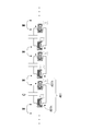
- FIG. 1 is a configuration diagram of a power supply system according to the first embodiment of the present invention.
- the power supply system 100 includes a power transmission device 200 and a power reception device 300.
- the front-rear direction is determined for each of the power transmission device 200 and the power reception device 300.
- the power transmission device 200 and the power reception device 300 are arranged at a distance, and the power reception device 300 side of the power transmission device 200 is the front side.
- the side farther from the power receiving device 300 in the power transmitting device 200 is the rear side.
- the power transmission device 200 side is defined as the front side.
- the side farther from the power transmission device 200 in the power reception device 300 is the rear side.
- the power transmission device 200 includes a power transmission coil unit 210 and a power feeding unit 280.
- the power transmission coil unit 210 includes a front coil unit 220, a rear coil unit 230, and a power feeding coil 240.
- the pre-stage coil unit 220 is composed of one resonance coil. This resonance coil is referred to as a front coil 221.
- the front coil 221 is a spring-type coil, and is disposed on the front side (that is, the power reception device 300 side) of the power supply coil 240.
- the rear coil unit 230 has two spring type coils, and is arranged behind the power supply coil 240 (that is, on the side far from the power receiving device 300).
- the first rear coil 231 and the second rear coil 232 are from the side closer to the feeding coil 240. That is, the feeding coil 240 is disposed so as to be sandwiched between the front coil 221 and the first rear coil 231.
- the front coil 221, the first rear coil 231 and the second rear coil 232 are arranged at a constant pitch.
- a structure configured by periodically arranging a plurality of resonance coils is referred to as a “coil periodic structure”.
- the axis of the front coil 221, the axis of the feeding coil 240, the axis of the first rear coil 231, and the axis of the second rear coil 232 are substantially coaxial, but the axes intersect each other.
- An angle may be attached as follows.
- the front coil 221, the first rear coil 231, and the second rear coil 232 are arranged at a substantially constant pitch. The arrangement pitch may be slightly deviated within the propagation range.
- the pre-stage coil 221, the first post-stage coil 231 and the second post-stage coil 232 have the same coil characteristics and the same resonance (resonance) frequency. That is, the resonance coils having different characteristics are not arranged, but a plurality of resonance coils having the same characteristics are arranged.
- the resonance frequency may be shifted within a range in which the electromagnetic wave can propagate.
- the resonance frequency varies due to manufacturing errors. The smaller the error is, the more desirable electromagnetic propagation characteristics can be obtained.
- the resonance frequency variation is about 10 kHz or less than the resonance frequency variation is about 100 kHz. Propagation characteristics can be obtained.
- Japanese Patent Application Laid-Open No. 2011-147271 only includes a plurality of resonance coils having different resonance frequencies so as to be compatible with a plurality of frequencies.
- Japanese Unexamined Patent Application Publication No. 2011-147271 discloses that a plurality of resonance coils are arranged as a transmission line as in the present embodiment, and that the transmission efficiency is improved by controlling the near magnetic field distribution. Not disclosed.
- the power feeding unit 280 includes a power source 281, a power application unit 282, and a frequency control unit 283.
- the power application unit 282 applies power to the feeding coil 240.
- the power application unit 282 causes an alternating current having a controlled frequency to flow through the feeding coil 240.
- the frequency control unit 283 controls the frequency of the current applied to the power feeding coil 240 by, for example, switching.
- the frequency control unit 283 may be provided with an adjusting unit for the user to manually adjust the frequency.
- the configuration of power reception device 300 is basically the same as that of power transmission device 200, and includes power reception coil unit 310 and power reception unit 380.
- the power receiving coil unit 310 includes a front coil unit 320, a rear coil unit 330, and a power receiving coil 340.
- the pre-stage coil unit 320 is composed of one resonance coil, and this is referred to as a pre-stage coil 321.
- the rear coil unit 330 includes a first rear coil 331 and a second rear coil 332.
- the power receiving coil 340 is disposed between the front coil 321 and the first rear coil 331.
- the power receiving unit 380 supplies the received power to the load 900 after rectifying the power received by the power receiving coil 340 or performing voltage conversion.
- FIG. 2 is a configuration diagram of a power supply system 10 as a background technique using an electromagnetic resonance phenomenon.
- a front coil 30 for power transmission is disposed in front of the power feeding coil 20, but no coil is disposed in the rear stage of the power feeding coil 20.
- the pre-stage coil 50 is arranged at the front stage of the power receiving coil 40, but the coil is not arranged at the rear stage of the power receiving coil 40. 2 is different from the configuration of the first embodiment in whether the power transmission coil unit 210 and the power reception coil unit 310 have a plurality of resonance coils.
- the power transmission efficiency is compared between the present embodiment of FIG. 1 and the background art of FIG.
- FIG. 3 is a result of measuring the power transmission efficiency by changing the distance between the first embodiment (FIG. 1) and the background art (FIG. 2).
- the horizontal axis is the distance [m]
- the vertical axis is the logarithm of the power transmission efficiency [%].
- the diameter of each coil was 20 cm, the height was 10 cm, and the number of turns was 19.
- the resonance frequency of each coil was adjusted to be around 8.64 MHz by cutting the copper wire at the coil end so that the variation was within 10 kHz. That is, the frequency of the power supplied to the power supply coils 20 and 240 was adjusted to 8.64 MHz.
- the power transmission efficiency of the first embodiment is increased when the distance exceeds 50 cm.
- the power transmission efficiency decreases as the distance increases.
- the power transmission efficiency does not decrease even when the distance increases, and is slightly increased depending on the viewpoint. Looks like. Since the diameter of one coil is 20 cm, it can be said that the present embodiment is more effective when the power transmission distance exceeds 2 to 3 times the coil diameter. Thus, according to this embodiment, it turns out that there exists an effect which can lengthen power transmission distance, keeping power transmission efficiency high.
- electromagnetic propagation wave As a result, for example, when a plurality of resonance coils 401 are arranged as shown in FIG. 4, it is possible to determine what mode of electromagnetic wave is generated there.
- this wave is referred to as “electromagnetic propagation wave”. That is, the present inventors expressed the relationship between the frequency (f) and the wave number (k) of the electromagnetic propagation wave that can occur in the periodic structure of the coil as a dispersion curve as shown in FIG. d represents one cycle length of the periodic structure, and is, for example, a center-to-center distance between adjacent coils. Therefore, “wave number (k) ⁇ one cycle length (d)” which is the horizontal axis of the graph of FIG. 5 means a phase change per cycle length.
- the coil periodic structure can be treated as an electromagnetic wave propagation region, that is, a transmission line when this structure is regarded as a metamaterial. .
- the inventors have come up with a configuration in which an arbitrary electric field distribution is generated in the periodic structure (transmission line).
- a method of obtaining a dispersion curve of electromagnetic propagation waves generated there by treating a resonance coil periodic structure in which resonance coils 401 are periodically arranged as a metamaterial will be described.
- the resonance coil 401 a spring type coil is taken as an example.
- An arrangement structure in which a plurality of coils 401 are arranged coaxially as in the power transmission coil unit 210 in FIG. 1 is replaced with the equivalent circuit in FIG. 6.
- M is a mutual inductance between adjacent coils 401.
- the capacitance component C is explicitly extracted, and the resistance component is ignored.
- the black circle in a figure shows the polarity of winding.
- FIG. 7 the circuit of FIG. 6 can be equivalently converted as shown in FIG. In FIG. 7, one coil 401 is depicted as being divided into two coil components 401h and 401h. Therefore, the inductance of one coil component 401h is L / 2.
- circuit of FIG. 7 can perform equivalent conversion as shown in FIG. 8 while paying attention to the polarity of the coil.
- one unit (one unit) of this periodic structure can be redrawn in the equivalent circuit of FIG.
- one unit (one unit) of the periodic structure can be expressed by the T matrix as follows.
- d be the periodic interval (distance between the centers of the coils) of this periodic structure.
- the wave number in the traveling direction of the electromagnetic propagation wave traveling through the metamaterial is k x .
- k x ⁇ d represents the phase of the wave for each period, and the following equation is established.
- the dispersion curve when the coil periodic structure is a metamaterial has been obtained.
- an electromagnetic field is transmitted to the adjacent resonance coil, and the coil periodic structure becomes a transmission line for electromagnetic propagation waves.
- the transmission line loss is small, the electromagnetic field distribution on the transmission line is a so-called standing wave distribution.
- a standing wave can be generated in a transmission line with a coil periodic structure. Furthermore, if a wave that satisfies the resonance condition of the coil periodic structure is generated, the number of antinodes of the standing wave (electromagnetic propagation wave) can be controlled.
- the number of coils is n
- the coil interval is d
- phase X is 0 ⁇ X ⁇ ⁇
- m 0, 1,... N ⁇ 1.
- the frequency of the feed power for example, the frequency of the alternating current
- a standing wave of electromagnetic propagation waves can be generated in the coil periodic structure (see, for example, FIG. 4).
- the number of nodes is 0 and the number of bellies is 1.
- magnetic resonance generated in the power transmission coil unit 210 and the power reception coil unit 310 can be controlled using such a phenomenon.
- the power transmission coil unit 210 and the power reception coil unit 310 are configured by three coils.
- stable standing waves are generated in the three coils (221, 231, 232) of the power transmission coil unit 210, and when a magnetic field loop is illustrated, the front coil 221 and the power receiving coil of the power transmission coil unit 210 as illustrated in FIG.
- the optimum magnetic field resonance state differs from the example of FIG. Of course.
- a stable standing wave can be created by creating a resonance state in the power transmission coil unit 210 (or the power reception coil unit 310) constituted by a plurality of resonance coils, and the power transmission coil unit 210 can thereby generate a power reception coil unit 310. There will be no change in the efficiency of power transmission.
- FIGS. 15 and 16 are a measurement system explanatory diagram and measurement results showing this.
- the distance between the coil periodic structure (the power transmission coil unit 210 and the power reception coil unit 310) and the floor surface 800 is set to 20 cm or 60 cm.
- FIG. 16 shows the results of measuring the power transmission efficiency in the above two cases. From FIG. 16, it can be seen that when the distance from the floor 800 is set to 20 cm, the power transmission efficiency is improved at a certain distance from the floor 800, rather than from 60 cm.
- the floor surface 800 and the coil periodic structure may be skillfully used to improve power transmission efficiency.
- a material that reflects or shields electromagnetic waves such as a metal plate, may be skillfully used to improve power transmission efficiency.
- the power supply coil 240 (power reception coil 340) is disposed immediately behind the front coil 221 (321).
- the power feeding coil 240 power receiving coil 340
- the power feeding coil 240 may be disposed anywhere between the plurality of resonance coils arranged.
- a feeding coil (or a receiving coil) may be arranged between the second and third from the front (right) while seven or more coils are arranged.
- the front coil part (220) is composed of two resonance coils 221 and 222
- the rear coil part is composed of the third and subsequent coils.
- the impedance of the resonance coil may be variable. By making the impedance of the resonance coil variable, the dispersion curve can be shifted as shown in FIG.
- the dielectric constant or magnetic permeability of the coil core may be controlled, or a variable capacitance may be added to the resonance coil to change the capacitance value of the variable capacitance.
- an impedance control unit 284 is provided in the power feeding unit. As described above, if the coil impedance is variable on the power transmission coil unit 210 side, a desired resonance state can be created in the power transmission coil unit 210 with respect to the fixed frequency.
- the impedances of all the coils constituting the power transmission coil unit may be changed at the same time, or the impedances of the individual coils may be individually changed and adjusted. Good.
- the impedances of all the coils may be changed at the same time, or the impedances of the individual coils may be individually changed and adjusted.
- a spring type coil is exemplified as the resonance coil.
- the resonance coil for example, a planar spiral coil shown in FIG. 20A may be used.
- the planar spiral coil 501 has an advantage that it can be mounted on a printed circuit board. That is, one spiral coil 501 may be mounted on the front surface or the back surface of the printed board. Alternatively, planar spiral coils may be mounted on both sides of the printed board.
- the planar spiral coil 501 of FIG. 20A is mounted on the front side of the printed board.
- the coil 502 of FIG. 20B is mounted on the back surface of the printed board.
- 20B is a perspective view of the coil 501 mounted on the back surface of the printed circuit board from the front surface side.
- a continuous spiral shape can be formed as double-sided mounting by conducting conductor connection between the front side coil 501 and the back side coil 502 at the junction point 503.
- various types of spiral conductors can be mounted on the multilayer substrate by using the spiral conductors of the respective layers and the conductors connecting the layers.
- 20A and 20B exemplify a spiral coil having a rectangular shape and each side of the rectangle having a linear shape, it goes without saying that it may be a curved spiral.
- the spiral coil may be mounted on the high dielectric substrate.
- a spiral coil may be mounted on the magnetic material.
- the space between the power transmission device and the power reception device is generally air, but water, seawater, soil, or a wall may be provided between the power transmission device and the power reception device.
- a plurality of power transmission coil units may be two-dimensionally arranged. Further, for example, as shown in FIG. 21, a plurality of power transmission coil sections (or power reception coil sections) arranged two-dimensionally are sandwiched between two rigid boards 611 and 612, and the power transmission coil section (or power reception coil section) ) May be rigid so that it does not bend. Alternatively, the power transmission coil unit or the power reception coil unit may be flexibly bent by sandwiching the resonance coil between two sheets having flexibility.
- the term “periodic structure” is used to express that the power transmission coil unit (or the power receiving coil unit) is composed of a periodic structure including a plurality of resonance coils.
- the periodic structure should not be construed to be limited to an array structure with a strictly constant pitch.
- the period may not be strictly constant, and it is allowed that the arrangement pitch of the resonance coils is deviated within a range in which the power transmission coil unit (or power reception coil unit) can be handled as a metamaterial in view of the whole purpose of the present invention.
- the arrangement pitch of the resonance coils is designed in consideration of manufacturing restrictions, so that the arrangement period is allowed to deviate depending on the manufacturing conditions.
- Examples of the load that receives power supply from the power receiving device include various applied products such as various sensors, household appliances, portable terminals, and electric vehicles.
- one power transmission coil part was equipped with one coil periodic structure.
- one power receiving coil portion has one coil periodic structure. This is because the frequency of magnetic field resonance between the power transmission coil unit and the power reception coil unit is one, but both the power transmission coil unit and the power reception coil unit may have a plurality of coil periodic structures. For example, when a plurality of coil periodic structures are provided in one power transmission coil unit (or power receiving coil unit), a second coil periodic structure may be provided inside the first coil periodic structure. According to such a configuration, power can be transmitted at one frequency, and a signal can be transmitted at another frequency.
- DESCRIPTION OF SYMBOLS 100 Electric power supply system, 200 ... Power transmission apparatus, 210 ... Power transmission coil part, 220 ... Pre-stage coil part, 221 ... Pre-stage coil part, 230 ... Rear stage coil part, 231 ... 1st latter stage coil, 232 ... 2nd latter stage coil, 240 ... feeding coil, 280 ... feeding part, 281 ... power supply, 282 ... power application part, 283 ... frequency control part, 284: Impedance control unit, 300 ... Power receiving device, 310 ... Power receiving coil unit, 320 ... Pre-coil unit, 321 ... Pre-coil, 330 ... Post-coil unit, 331 ... First rear coil, 332 ...
Abstract
The invention addresses the problem of providing, in wireless power supply, a power supply system capable of maintaining a relatively high power transmission efficiency even when a power transmission distance is long. A power transmitting coil unit (210) has a plurality of resonance coils (221) arranged so as to form a periodical structure. The resonance coils (221) form a transmission line for an electromagnetic wave, and a standing wave of an electromagnetic propagating wave occurs in the power transmitting coil unit (210). Similarly, a power receiving coil unit (310) has a plurality of resonance coils (321) arranged so as to form a periodical structure. The power transmission efficiency is maintained relatively high even if the distance between a power transmitting device (200) and a power receiving device (300) exceeds twice.
Description
本発明は、電力送受信システムに関し、具体的には、送電線を介さずに非接触で受電装置に電力を供給するシステムに関する。
The present invention relates to a power transmission / reception system, and more specifically, to a system for supplying power to a power receiving device in a contactless manner without going through a power transmission line.
離間した受電装置に対し無線で電力を供給する方法が知られている。
例えば、特開2008-66841号公報(特許文献1)では、電磁波伝送シートのなかを電磁波を伝搬させ、シートから漏出する電磁界を受電装置に供給するという構成が開示されている(他に、特開2007-281678号公報(特許文献2))。 A method of supplying power wirelessly to a separated power receiving apparatus is known.
For example, Japanese Patent Laid-Open No. 2008-66841 (Patent Document 1) discloses a configuration in which an electromagnetic wave propagates in an electromagnetic wave transmission sheet and an electromagnetic field leaking from the sheet is supplied to a power receiving device (in addition, JP 2007-281678 (Patent Document 2)).
あるいは、特開2008-259392号公報(特許文献3)には、マイクロ波ビームを利用した送電方法が開示されている。これは、例えば、衛生軌道上で太陽光発電を行い、そのエネルギーをマイクロ波ビームで地上に送る。そして、地上の受電システムでマイクロ波を電力に再変換するというものである。
Alternatively, Japanese Patent Laid-Open No. 2008-259392 (Patent Document 3) discloses a power transmission method using a microwave beam. For example, solar power generation is performed on a sanitary orbit, and the energy is transmitted to the ground with a microwave beam. Then, the microwave is reconverted into electric power by the ground power receiving system.
また、例えば、特開平7-322534号公報(特許文献4)にあるように、電源側の一次コイルから負荷側の二次コイルに電磁誘導で電力を伝送する方式がある。これは、家庭用の小型電子機器、例えば、シェーバーや電動歯ブラシなどの充電によく使用されている。
Further, for example, as disclosed in Japanese Patent Application Laid-Open No. 7-322534 (Patent Document 4), there is a method of transmitting electric power from a power source side primary coil to a load side secondary coil by electromagnetic induction. This is often used to charge small household electronic devices such as shavers and electric toothbrushes.
また、電磁誘導では給電元と給電先(受電側)とが極めて接近していなくてはならないが、この欠点を解消すべく電磁共鳴現象を利用した電力伝送も提案されている(特開2011―147271号公報(特許文献5)、US7825543B2(特許文献6))。
Further, in electromagnetic induction, the power supply source and the power supply destination (power receiving side) must be very close to each other, but power transmission using an electromagnetic resonance phenomenon has also been proposed in order to eliminate this drawback (Japanese Patent Laid-Open No. 2011-2011). No. 147271 (Patent Document 5), US7825543B2 (Patent Document 6)).
上記特許文献5、6のように電磁共鳴を利用する方法は、電磁誘導方式に比べれば送電距離を延ばせるという利点がある。
しかし、上記特許文献5の方法でも、送電距離が送電コイルの直径の2倍ないしは3倍程度を超えてくると、極端に送電効率が下がってしまうという問題があった。 The methods using electromagnetic resonance as in Patent Documents 5 and 6 have an advantage that the power transmission distance can be extended as compared with the electromagnetic induction method.
However, even the method ofPatent Document 5 has a problem that the power transmission efficiency is extremely lowered when the power transmission distance exceeds about twice or three times the diameter of the power transmission coil.
しかし、上記特許文献5の方法でも、送電距離が送電コイルの直径の2倍ないしは3倍程度を超えてくると、極端に送電効率が下がってしまうという問題があった。 The methods using electromagnetic resonance as in
However, even the method of
そこで、本発明の目的は、無線給電において、送電距離が長い場合でも比較的高い送電効率を維持できる送電装置、受電装置、および電力供給システムを提供することにある。
Therefore, an object of the present invention is to provide a power transmission device, a power reception device, and a power supply system that can maintain a relatively high power transmission efficiency even when a power transmission distance is long in wireless power feeding.
本発明の送電装置は、
一次元的に周期構造をなすように配列された複数の共鳴コイルを有し、受電装置と磁界共鳴することによって前記受電装置に電力を送電する送電コイル部と、
前記送電コイル部に電力を供給する給電部と、を備え、
前記送電コイル部を電磁伝搬波の伝送路とし、この送電コイル部に電磁伝搬波の定在波を発生させる
ことを特徴とする。 The power transmission device of the present invention is
A power transmission coil unit that has a plurality of resonance coils arranged so as to form a one-dimensional periodic structure, and transmits power to the power reception device by magnetic field resonance with the power reception device;
A power supply unit that supplies power to the power transmission coil unit,
The power transmission coil section is used as a transmission path for electromagnetic propagation waves, and a standing wave of electromagnetic propagation waves is generated in the power transmission coil section.
本発明の受電装置は、
一次元的に周期構造をなすように配列された複数の共鳴コイルを有し、送電装置と磁界共鳴することによって前記送電装置から電力を受電する受電コイル部と、
前記受電コイル部から電力を受電する受電部と、を備え、
前記受電コイル部が電磁伝搬波の伝送路となり、前記送電装置との磁界共鳴によってこの受電コイル部に電磁伝搬波の定在波が生じる
ことを特徴とする。 The power receiving device of the present invention is
A plurality of resonance coils arranged so as to form a one-dimensional periodic structure, and a power receiving coil unit that receives power from the power transmission device by magnetic field resonance with the power transmission device;
A power receiving unit that receives power from the power receiving coil unit,
The power receiving coil portion serves as an electromagnetic propagation wave transmission path, and a standing wave of the electromagnetic propagation wave is generated in the power receiving coil portion due to magnetic field resonance with the power transmission device.
本発明の電力供給システムは、前記送電装置と、前記受電装置と、を備えることを特徴とする。
A power supply system according to the present invention includes the power transmission device and the power reception device.
このような構成によれば、送電距離が比較的長くても送電効率を高く保つことができるという効果を奏することができる。
According to such a configuration, there is an effect that the power transmission efficiency can be kept high even if the power transmission distance is relatively long.
(第1実施形態)
図1は、本発明の第1実施形態に係る電力供給システムの構成図である。
電力供給システム100は、送電装置200と、受電装置300と、を備えている。
ここで、説明が分かりやすいように、送電装置200と受電装置300とのそれぞれに前後方向の向きを定める。
本明細書では、送電装置200と受電装置300とは距離を隔てて配置されているところ、送電装置200において受電装置300の側を前側とする。送電装置200において受電装置300から遠い側を後ろ側とする。
同様に、受電装置300において送電装置200の側を前側とする。受電装置300において送電装置200から遠い側を後ろ側とする。 (First embodiment)
FIG. 1 is a configuration diagram of a power supply system according to the first embodiment of the present invention.
Thepower supply system 100 includes a power transmission device 200 and a power reception device 300.
Here, for easy understanding, the front-rear direction is determined for each of thepower transmission device 200 and the power reception device 300.
In this specification, thepower transmission device 200 and the power reception device 300 are arranged at a distance, and the power reception device 300 side of the power transmission device 200 is the front side. The side farther from the power receiving device 300 in the power transmitting device 200 is the rear side.
Similarly, in thepower receiving device 300, the power transmission device 200 side is defined as the front side. The side farther from the power transmission device 200 in the power reception device 300 is the rear side.
図1は、本発明の第1実施形態に係る電力供給システムの構成図である。
電力供給システム100は、送電装置200と、受電装置300と、を備えている。
ここで、説明が分かりやすいように、送電装置200と受電装置300とのそれぞれに前後方向の向きを定める。
本明細書では、送電装置200と受電装置300とは距離を隔てて配置されているところ、送電装置200において受電装置300の側を前側とする。送電装置200において受電装置300から遠い側を後ろ側とする。
同様に、受電装置300において送電装置200の側を前側とする。受電装置300において送電装置200から遠い側を後ろ側とする。 (First embodiment)
FIG. 1 is a configuration diagram of a power supply system according to the first embodiment of the present invention.
The
Here, for easy understanding, the front-rear direction is determined for each of the
In this specification, the
Similarly, in the
送電装置200は、送電コイル部210と、給電部280と、を備える。
送電コイル部210は、前段コイル部220と、後段コイル部230と、給電コイル240と、を備えている。
前段コイル部220は一つの共鳴コイルで構成されている。この共鳴コイルを前段コイル221とする。前段コイル221は、スプリング型のコイルであって、給電コイル240よりも前側(すなわち受電装置300側)に配置されている。
後段コイル部230は、二つのスプリング型コイルを有し、給電コイル240よりも後ろ側(すなわち受電装置300から遠い側)に配置されている。
ここでは、給電コイル240に近い方から、第1後段コイル231、第2後段コイル232、とする。すなわち、給電コイル240は、前段コイル221と第1後段コイル231との間に挟まれるように配置されている。 Thepower transmission device 200 includes a power transmission coil unit 210 and a power feeding unit 280.
The powertransmission coil unit 210 includes a front coil unit 220, a rear coil unit 230, and a power feeding coil 240.
Thepre-stage coil unit 220 is composed of one resonance coil. This resonance coil is referred to as a front coil 221. The front coil 221 is a spring-type coil, and is disposed on the front side (that is, the power reception device 300 side) of the power supply coil 240.
Therear coil unit 230 has two spring type coils, and is arranged behind the power supply coil 240 (that is, on the side far from the power receiving device 300).
Here, it is assumed that the firstrear coil 231 and the second rear coil 232 are from the side closer to the feeding coil 240. That is, the feeding coil 240 is disposed so as to be sandwiched between the front coil 221 and the first rear coil 231.
送電コイル部210は、前段コイル部220と、後段コイル部230と、給電コイル240と、を備えている。
前段コイル部220は一つの共鳴コイルで構成されている。この共鳴コイルを前段コイル221とする。前段コイル221は、スプリング型のコイルであって、給電コイル240よりも前側(すなわち受電装置300側)に配置されている。
後段コイル部230は、二つのスプリング型コイルを有し、給電コイル240よりも後ろ側(すなわち受電装置300から遠い側)に配置されている。
ここでは、給電コイル240に近い方から、第1後段コイル231、第2後段コイル232、とする。すなわち、給電コイル240は、前段コイル221と第1後段コイル231との間に挟まれるように配置されている。 The
The power
The
The
Here, it is assumed that the first
前段コイル221、第1後段コイル231および第2後段コイル232は、一定ピッチで配列されている。
このように複数の共鳴コイルが周期配列されることで構成される構造を本明細書では、「コイル周期構造」と称する。 Thefront coil 221, the first rear coil 231 and the second rear coil 232 are arranged at a constant pitch.
In this specification, a structure configured by periodically arranging a plurality of resonance coils is referred to as a “coil periodic structure”.
このように複数の共鳴コイルが周期配列されることで構成される構造を本明細書では、「コイル周期構造」と称する。 The
In this specification, a structure configured by periodically arranging a plurality of resonance coils is referred to as a “coil periodic structure”.
図1においては、前段コイル221の軸と、給電コイル240の軸と、第1後段コイル231の軸と、第2後段コイル232の軸と、はほぼ同軸であるが、互いの軸線が交差するように角度がついていてもよい。
図1においては、前段コイル221と、第1後段コイル231と、第2後段コイル232と、はほぼ一定のピッチで配置されているが、後の説明で明らかになるように、電磁伝搬波を伝搬できる範囲で配列ピッチが多少ずれていてもよい。
前段コイル221と、第1後段コイル231と、第2後段コイル232と、は、コイル特性としては同じであり、共鳴(共振)周波数も同じになる。すなわち、異なる特性の共鳴コイルを並べているのではなく、同じ特性をもつ複数の共鳴コイルを配列している、ということである。 In FIG. 1, the axis of thefront coil 221, the axis of the feeding coil 240, the axis of the first rear coil 231, and the axis of the second rear coil 232 are substantially coaxial, but the axes intersect each other. An angle may be attached as follows.
In FIG. 1, thefront coil 221, the first rear coil 231, and the second rear coil 232 are arranged at a substantially constant pitch. The arrangement pitch may be slightly deviated within the propagation range.
Thepre-stage coil 221, the first post-stage coil 231 and the second post-stage coil 232 have the same coil characteristics and the same resonance (resonance) frequency. That is, the resonance coils having different characteristics are not arranged, but a plurality of resonance coils having the same characteristics are arranged.
図1においては、前段コイル221と、第1後段コイル231と、第2後段コイル232と、はほぼ一定のピッチで配置されているが、後の説明で明らかになるように、電磁伝搬波を伝搬できる範囲で配列ピッチが多少ずれていてもよい。
前段コイル221と、第1後段コイル231と、第2後段コイル232と、は、コイル特性としては同じであり、共鳴(共振)周波数も同じになる。すなわち、異なる特性の共鳴コイルを並べているのではなく、同じ特性をもつ複数の共鳴コイルを配列している、ということである。 In FIG. 1, the axis of the
In FIG. 1, the
The
ただし、同じコイル特性といっても、電磁伝搬波を伝搬できる範囲で共鳴周波数がずれていても良い。例えば、同じ特性を持つコイルでも、厳密には共鳴周波数は製造誤差によるばらつきがある。
なお、誤差が小さいほど、望ましい電磁伝搬特性を得ることができる。例えば、8.6MHz近辺に共鳴周波数を有する複数のコイルを使用する場合、共鳴周波数のバラツキが100kHz程度であるよりも、共鳴周波数のバラツキが10kHz程度かそれ以内に収まっている方が、望ましい電磁伝搬特性を得ることができる。 However, even if the coil characteristics are the same, the resonance frequency may be shifted within a range in which the electromagnetic wave can propagate. For example, even in a coil having the same characteristics, strictly speaking, the resonance frequency varies due to manufacturing errors.
The smaller the error is, the more desirable electromagnetic propagation characteristics can be obtained. For example, when using a plurality of coils having a resonance frequency in the vicinity of 8.6 MHz, it is preferable that the resonance frequency variation is about 10 kHz or less than the resonance frequency variation is about 100 kHz. Propagation characteristics can be obtained.
この点、特開2011―147271号公報では、複数の周波数に対応可能なように共鳴周波数が異なる複数の共鳴コイルを備えるだけである。
本実施形態のごとく複数の共鳴コイルを配列してこれを伝送線路とすることや、近傍磁界分布を制御して伝送効率を向上させようとすることについては、特開2011―147271号公報には開示されていない。 In this regard, Japanese Patent Application Laid-Open No. 2011-147271 only includes a plurality of resonance coils having different resonance frequencies so as to be compatible with a plurality of frequencies.
Japanese Unexamined Patent Application Publication No. 2011-147271 discloses that a plurality of resonance coils are arranged as a transmission line as in the present embodiment, and that the transmission efficiency is improved by controlling the near magnetic field distribution. Not disclosed.
給電部280は、電源281と、電力印加部282と、周波数制御部283と、を備える。
電力印加部282は、給電コイル240に電力を印加する。
ここでは、電力印加部282は、制御された周波数の交流電流を給電コイル240に流す。
周波数制御部283は、給電コイル240に印加する電流の周波数を例えばスイッチングなどによって制御する。
明示的に図示しないが、周波数制御部283には、ユーザが手動で周波数を調整するための調整手段が付設されていてもよい。 Thepower feeding unit 280 includes a power source 281, a power application unit 282, and a frequency control unit 283.
Thepower application unit 282 applies power to the feeding coil 240.
Here, thepower application unit 282 causes an alternating current having a controlled frequency to flow through the feeding coil 240.
Thefrequency control unit 283 controls the frequency of the current applied to the power feeding coil 240 by, for example, switching.
Although not explicitly shown, thefrequency control unit 283 may be provided with an adjusting unit for the user to manually adjust the frequency.
電力印加部282は、給電コイル240に電力を印加する。
ここでは、電力印加部282は、制御された周波数の交流電流を給電コイル240に流す。
周波数制御部283は、給電コイル240に印加する電流の周波数を例えばスイッチングなどによって制御する。
明示的に図示しないが、周波数制御部283には、ユーザが手動で周波数を調整するための調整手段が付設されていてもよい。 The
The
Here, the
The
Although not explicitly shown, the
受電装置300の構成は、基本的には送電装置200と同じであり、受電コイル部310と、受電部380と、を備える。
受電コイル部310は、前段コイル部320と、後段コイル部330と、受電コイル340と、を備える。
前段コイル部320は、一つの共鳴コイルで構成され、これを前段コイル321と称する。
後段コイル部330は、第1後段コイル331と、第2後段コイル332と、を有する。
前段コイル321と第1後段コイル331との間に受電コイル340が挟まれるように配置されている。
受電部380は、受電コイル340で受電した電力を整流したり、電圧変換するなどの処理をした後、受電した電力を負荷900に供給する。 The configuration ofpower reception device 300 is basically the same as that of power transmission device 200, and includes power reception coil unit 310 and power reception unit 380.
The powerreceiving coil unit 310 includes a front coil unit 320, a rear coil unit 330, and a power receiving coil 340.
Thepre-stage coil unit 320 is composed of one resonance coil, and this is referred to as a pre-stage coil 321.
Therear coil unit 330 includes a first rear coil 331 and a second rear coil 332.
Thepower receiving coil 340 is disposed between the front coil 321 and the first rear coil 331.
Thepower receiving unit 380 supplies the received power to the load 900 after rectifying the power received by the power receiving coil 340 or performing voltage conversion.
受電コイル部310は、前段コイル部320と、後段コイル部330と、受電コイル340と、を備える。
前段コイル部320は、一つの共鳴コイルで構成され、これを前段コイル321と称する。
後段コイル部330は、第1後段コイル331と、第2後段コイル332と、を有する。
前段コイル321と第1後段コイル331との間に受電コイル340が挟まれるように配置されている。
受電部380は、受電コイル340で受電した電力を整流したり、電圧変換するなどの処理をした後、受電した電力を負荷900に供給する。 The configuration of
The power
The
The
The
The
このような構成において、電力印加部282から給電コイル240に電力を印加すると、送電コイル部210から電磁波が送電される。
送電された電磁波を受電コイル部310で受信し、この電力を受電コイル340から取り出す。 In such a configuration, when power is applied from thepower application unit 282 to the power supply coil 240, electromagnetic waves are transmitted from the power transmission coil unit 210.
The received electromagnetic wave is received by the receivingcoil unit 310 and the electric power is taken out from the receiving coil 340.
送電された電磁波を受電コイル部310で受信し、この電力を受電コイル340から取り出す。 In such a configuration, when power is applied from the
The received electromagnetic wave is received by the receiving
本実施形態の構成を背景技術と対比する。
図2は、電磁共鳴現象を利用した背景技術としての電力供給システム10の構成図である。
給電コイル20の前段に送電用の前段コイル30が配置されているが、給電コイル20の後段にはコイルが配置されていない。
同様に、受電コイル40の前段に前段コイル50が配置されているが、受電コイル40の後段にはコイルが配置されていない。
図2の背景技術を本第1実施形態の構成と比べると、送電コイル部210および受電コイル部310が複数の共鳴コイルを有するか否かに違いがある。 The configuration of the present embodiment is compared with the background art.
FIG. 2 is a configuration diagram of apower supply system 10 as a background technique using an electromagnetic resonance phenomenon.
Afront coil 30 for power transmission is disposed in front of the power feeding coil 20, but no coil is disposed in the rear stage of the power feeding coil 20.
Similarly, thepre-stage coil 50 is arranged at the front stage of the power receiving coil 40, but the coil is not arranged at the rear stage of the power receiving coil 40.
2 is different from the configuration of the first embodiment in whether the powertransmission coil unit 210 and the power reception coil unit 310 have a plurality of resonance coils.
図2は、電磁共鳴現象を利用した背景技術としての電力供給システム10の構成図である。
給電コイル20の前段に送電用の前段コイル30が配置されているが、給電コイル20の後段にはコイルが配置されていない。
同様に、受電コイル40の前段に前段コイル50が配置されているが、受電コイル40の後段にはコイルが配置されていない。
図2の背景技術を本第1実施形態の構成と比べると、送電コイル部210および受電コイル部310が複数の共鳴コイルを有するか否かに違いがある。 The configuration of the present embodiment is compared with the background art.
FIG. 2 is a configuration diagram of a
A
Similarly, the
2 is different from the configuration of the first embodiment in whether the power
図1の本実施形態と図2の背景技術とで送電効率を比較する。
図3は、第1実施形態(図1)と背景技術(図2)とで、距離を変えて送電効率を測定した結果である。
図3のグラフにおいて、横軸は距離[m]であり、縦軸は送電効率[%]の対数である。
なお、各コイルの直径を20cm、高さを10cm、巻き数を19とした。
尚、各コイルの共振周波数は8.64MHz近辺で、バラツキが10kHz以内となるようにコイル端部の銅線を切断して調整した。
すなわち、給電コイル20、240に給電する電力の周波数を8.64MHzに調整した。 The power transmission efficiency is compared between the present embodiment of FIG. 1 and the background art of FIG.
FIG. 3 is a result of measuring the power transmission efficiency by changing the distance between the first embodiment (FIG. 1) and the background art (FIG. 2).
In the graph of FIG. 3, the horizontal axis is the distance [m], and the vertical axis is the logarithm of the power transmission efficiency [%].
The diameter of each coil was 20 cm, the height was 10 cm, and the number of turns was 19.
The resonance frequency of each coil was adjusted to be around 8.64 MHz by cutting the copper wire at the coil end so that the variation was within 10 kHz.
That is, the frequency of the power supplied to the power supply coils 20 and 240 was adjusted to 8.64 MHz.
図3を見ると、距離が50cmあたりまでは第1実施形態と背景技術とで送電効率にほとんど差がないか、むしろ背景技術の送電効率の方が高い。しかし、距離が50cmを超えたあたりから第1実施形態の送電効率が高くなる。そして、背景技術では、距離が長くなるほど送電効率は下がっていくのに対し、本第1実施形態の構成によれば距離が長くなっても送電効率が落ちず、見方によってはやや上昇しているようにも見える。
一のコイルの直径が20cmであることから、本実施形態は、送電距離がコイル直径の2倍から3倍を超える距離になったときにより効果を発揮するといえる。
このように、本実施形態によれば、送電効率を高く保ったまま送電距離を長くできる効果があることがわかる。 Referring to FIG. 3, until the distance is around 50 cm, there is almost no difference in power transmission efficiency between the first embodiment and the background technology, or rather, the power transmission efficiency of the background technology is higher. However, the power transmission efficiency of the first embodiment is increased when the distance exceeds 50 cm. In the background art, the power transmission efficiency decreases as the distance increases. However, according to the configuration of the first embodiment, the power transmission efficiency does not decrease even when the distance increases, and is slightly increased depending on the viewpoint. Looks like.
Since the diameter of one coil is 20 cm, it can be said that the present embodiment is more effective when the power transmission distance exceeds 2 to 3 times the coil diameter.
Thus, according to this embodiment, it turns out that there exists an effect which can lengthen power transmission distance, keeping power transmission efficiency high.
(原理説明)
上記のように本実施形態の作用効果が生じる理由は必ずしも定かではないが、本発明者らの着想を以下に簡単に説明する。
なお、仮に現時点での原理説明が誤りを含んでいたとしても、本発明の構成はもちろん、作用、効果が否定されるものではない。
本発明者らは、鋭意研究の末、複数の共鳴コイルを配列して周期構造となし、これを電磁界の伝送線路とみなすことに着想した。さらに、この周期構造を特定の周波数帯域で共鳴させたとき、この構造自体がメタマテリアルとして扱えることに着想した。そこで、この周期構造(伝送線路)に生じる電磁界分布を解析的に取り扱う方法を追求し、これをなし得た。つまり、共鳴コイルの周期構造に波のどのような伝搬モードが生じるかを解析的に求める方法を開発した。 (Principle explanation)
The reason why the effects of the present embodiment occur as described above is not necessarily clear, but the idea of the present inventors will be briefly described below.
Even if the current explanation of the principle includes an error, the operation and effect are not denied as well as the configuration of the present invention.
As a result of diligent research, the present inventors have conceived that a plurality of resonance coils are arranged to form a periodic structure, which is regarded as an electromagnetic field transmission line. Furthermore, when this periodic structure was resonated in a specific frequency band, the idea was that this structure itself could be treated as a metamaterial. Therefore, a method for analytically handling the electromagnetic field distribution generated in the periodic structure (transmission line) was pursued, and this could be achieved. In other words, a method has been developed to analytically determine what wave propagation mode occurs in the periodic structure of the resonant coil.
これによって、例えば、図4のように複数の共鳴コイル401を配列した時に、そこにどのようなモードの電磁波が発生するかを求めることができるようになった。
以後、この波を"電磁伝搬波"と称することにする。
すなわち、本発明者らは、コイルの周期構造に発生しうる電磁伝搬波の周波数(f)と波数(k)との関係を図5のような分散曲線として表した。
dは、周期構造の一周期長を表し、例えば、隣接するコイル同士の中心間距離である。したがって、図5のグラフの横軸である「波数(k)×一周期長(d)」は、一周期長あたりの位相変化を意味する。 As a result, for example, when a plurality of resonance coils 401 are arranged as shown in FIG. 4, it is possible to determine what mode of electromagnetic wave is generated there.
Hereinafter, this wave is referred to as “electromagnetic propagation wave”.
That is, the present inventors expressed the relationship between the frequency (f) and the wave number (k) of the electromagnetic propagation wave that can occur in the periodic structure of the coil as a dispersion curve as shown in FIG.
d represents one cycle length of the periodic structure, and is, for example, a center-to-center distance between adjacent coils. Therefore, “wave number (k) × one cycle length (d)” which is the horizontal axis of the graph of FIG. 5 means a phase change per cycle length.
図5の分散曲線で、fmaxとfminとの間の周波数fにおいて、コイル周期構造は、この構造をメタマテリアルとみたてた場合の電磁波の伝播領域、すなわち伝送線路として扱えるということがわかる。そして、この周期構造(伝送線路)に随意の電界分布を生じさせる構成に想到した。
In the dispersion curve of FIG. 5, at a frequency f between f max and f min , it can be seen that the coil periodic structure can be treated as an electromagnetic wave propagation region, that is, a transmission line when this structure is regarded as a metamaterial. . The inventors have come up with a configuration in which an arbitrary electric field distribution is generated in the periodic structure (transmission line).
(電磁伝搬波の分散曲線を求める理論)
共鳴コイル401を周期的に配列した共鳴コイル周期構造をメタマテリアルとして扱い、そこに生じる電磁伝搬波の分散曲線を求める方法を説明する。
ここでは、共鳴コイル401としては、スプリング型コイルを例にする。
図1の送電コイル部210のように、同軸に複数のコイル401が並んだ配列構造を図6の等価回路に置き換える。
ここで、Mは隣接するコイル401同士の相互インダクタンスである。
また、容量成分Cを明示的に取り出し、抵抗成分は無視している。
また、図中の黒丸は、巻線の極性を示す。 (Theory for obtaining the dispersion curve of electromagnetic wave propagation)
A method of obtaining a dispersion curve of electromagnetic propagation waves generated there by treating a resonance coil periodic structure in which resonance coils 401 are periodically arranged as a metamaterial will be described.
Here, as theresonance coil 401, a spring type coil is taken as an example.
An arrangement structure in which a plurality ofcoils 401 are arranged coaxially as in the power transmission coil unit 210 in FIG. 1 is replaced with the equivalent circuit in FIG. 6.
Here, M is a mutual inductance betweenadjacent coils 401.
In addition, the capacitance component C is explicitly extracted, and the resistance component is ignored.
Moreover, the black circle in a figure shows the polarity of winding.
共鳴コイル401を周期的に配列した共鳴コイル周期構造をメタマテリアルとして扱い、そこに生じる電磁伝搬波の分散曲線を求める方法を説明する。
ここでは、共鳴コイル401としては、スプリング型コイルを例にする。
図1の送電コイル部210のように、同軸に複数のコイル401が並んだ配列構造を図6の等価回路に置き換える。
ここで、Mは隣接するコイル401同士の相互インダクタンスである。
また、容量成分Cを明示的に取り出し、抵抗成分は無視している。
また、図中の黒丸は、巻線の極性を示す。 (Theory for obtaining the dispersion curve of electromagnetic wave propagation)
A method of obtaining a dispersion curve of electromagnetic propagation waves generated there by treating a resonance coil periodic structure in which resonance coils 401 are periodically arranged as a metamaterial will be described.
Here, as the
An arrangement structure in which a plurality of
Here, M is a mutual inductance between
In addition, the capacitance component C is explicitly extracted, and the resistance component is ignored.
Moreover, the black circle in a figure shows the polarity of winding.
さらに、図6の回路は図7のように等価変換できる。
図7では、一つのコイル401を二つのコイル成分401h、401hに分けたように描いている。
従って、一方のコイル成分401hのインダクタンスはL/2である。 Further, the circuit of FIG. 6 can be equivalently converted as shown in FIG.
In FIG. 7, onecoil 401 is depicted as being divided into two coil components 401h and 401h.
Therefore, the inductance of onecoil component 401h is L / 2.
図7では、一つのコイル401を二つのコイル成分401h、401hに分けたように描いている。
従って、一方のコイル成分401hのインダクタンスはL/2である。 Further, the circuit of FIG. 6 can be equivalently converted as shown in FIG.
In FIG. 7, one
Therefore, the inductance of one
さらに、図7の回路は、コイルの極性に注意しつつ、図8のように等価変換できる。
Furthermore, the circuit of FIG. 7 can perform equivalent conversion as shown in FIG. 8 while paying attention to the polarity of the coil.
さらに、この周期構造の一単位(一ユニット)は、図9の等価回路に描き直すことができる。
Furthermore, one unit (one unit) of this periodic structure can be redrawn in the equivalent circuit of FIG.
すると、周期構造の一単位(一ユニット)を、Tマトリクスによって次のように表すことができる。
Then, one unit (one unit) of the periodic structure can be expressed by the T matrix as follows.

この周期構造の周期間隔(コイルの中心間距離)をdとする。
また、周期構造をメタマテリアルとしたとき、このメタマテリアルを進行する電磁伝搬波の進行方向の波数をkxとする。
すると、kx×dは、一周期ごとの波の位相を表し、次の式が成立する。 Let d be the periodic interval (distance between the centers of the coils) of this periodic structure.
Further, when the periodic structure is a metamaterial, the wave number in the traveling direction of the electromagnetic propagation wave traveling through the metamaterial is k x .
Then, k x × d represents the phase of the wave for each period, and the following equation is established.

上記の式を用いて、位相(kx×d)と周波数f(=ω/2π)との関係をプロットすることにより分散関係が求まる。
これにより、メタマテリアルに生じる(電磁界の)波の周波数帯域(fmin<f<fmax)が求まる。すなわち、周波数帯域(fmin<f<fmax)において図3の分散曲線を描くことができる。 Using the above equation, the dispersion relationship can be obtained by plotting the relationship between the phase (k x × d) and the frequency f (= ω / 2π).
Thereby, the frequency band (f min <f <f max ) of the wave (electromagnetic field) generated in the metamaterial is obtained. That is, the dispersion curve of FIG. 3 can be drawn in the frequency band (f min <f <f max ).
ここまででコイル周期構造をメタマテリアルとした場合の分散曲線が求められた。
このコイル周期構造になんらかの給電を行った場合、電磁界が隣接する共鳴コイルに伝わっていき、コイル周期構造が電磁伝搬波の伝送線路となる。さらに、伝送線路の損失が小さければ、伝送線路上の電磁界分布は、いわゆる定在波分布となる。 So far, the dispersion curve when the coil periodic structure is a metamaterial has been obtained.
When any power is supplied to this coil periodic structure, an electromagnetic field is transmitted to the adjacent resonance coil, and the coil periodic structure becomes a transmission line for electromagnetic propagation waves. Furthermore, if the transmission line loss is small, the electromagnetic field distribution on the transmission line is a so-called standing wave distribution.
コイル周期構造を伝送線路とし、これに定在波を発生させることができることがわかった。さらに、コイル周期構造の共振条件を満たすような波を発生させれば、定在波(電磁伝搬波)の腹の数をコントロールできることになる。
コイル数をn、コイル間隔をd、隣接コイル間の位相(分散曲線におけるある周波数fに対する位相)をX(=kx×d)[radian]とする。
共振条件を満たすとすると次の式が成立することになる。 It turned out that a standing wave can be generated in a transmission line with a coil periodic structure. Furthermore, if a wave that satisfies the resonance condition of the coil periodic structure is generated, the number of antinodes of the standing wave (electromagnetic propagation wave) can be controlled.
The number of coils is n, the coil interval is d, and the phase between adjacent coils (phase with respect to a certain frequency f in the dispersion curve) is X (= kx × d) [radian].
If the resonance condition is satisfied, the following equation is established.
(n-1)X=mπ (mは整数)
(N-1) X = mπ (m is an integer)
ここで、位相Xは、0≦X≦πであるので、上記式を満たすmは、m=0、1、・・・・n-1、のn個である。
例えば、コイルの個数が9個である場合(n=9)、m=0、1、・・・8、の9個の共振状態を満たす位相Xがあることになる。
給電電力の周波数(例えば交流電流の周波数)を制御して共振状態とすることにより、コイル周期構造に電磁伝搬波の定在波を発生させることができる(例えば図4参照)。 Here, since the phase X is 0 ≦ X ≦ π, m satisfying the above equation is n, m = 0, 1,... N−1.
For example, when the number of coils is nine (n = 9), there are phases X that satisfy nine resonance states of m = 0, 1,.
By controlling the frequency of the feed power (for example, the frequency of the alternating current) to achieve a resonance state, a standing wave of electromagnetic propagation waves can be generated in the coil periodic structure (see, for example, FIG. 4).
なお、m=0とは、図10のように、すべてのコイルが同相であるということであり、磁界ベクトルがすべてのコイルで同位相になっているということである。
この場合、節の数は0、腹の数は1である。 Note that m = 0 means that all coils are in phase as shown in FIG. 10, and that the magnetic field vector is in phase with all coils.
In this case, the number of nodes is 0 and the number of bellies is 1.
この場合、節の数は0、腹の数は1である。 Note that m = 0 means that all coils are in phase as shown in FIG. 10, and that the magnetic field vector is in phase with all coils.
In this case, the number of nodes is 0 and the number of bellies is 1.
また、例えば、m=1とは、節の数が1、腹の数が2、ということである。
n=3の場合でいうと、図11のように、磁界ベクトルは両端のコイルで互いに逆向きになっており、中央は節になる。 For example, m = 1 means that the number of nodes is 1 and the number of antinodes is 2.
In the case of n = 3, as shown in FIG. 11, the magnetic field vectors are opposite to each other in the coils at both ends, and the center is a node.
n=3の場合でいうと、図11のように、磁界ベクトルは両端のコイルで互いに逆向きになっており、中央は節になる。 For example, m = 1 means that the number of nodes is 1 and the number of antinodes is 2.
In the case of n = 3, as shown in FIG. 11, the magnetic field vectors are opposite to each other in the coils at both ends, and the center is a node.
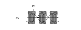
また、例えば、m=2とは、節の数が2、腹の数が3、ということである。
n=3の場合でいうと、図12のように、磁界ベクトルは一周期ごとに180°ずれる。 For example, m = 2 means that the number of nodes is 2 and the number of bellies is 3.
In the case of n = 3, as shown in FIG. 12, the magnetic field vector is shifted by 180 ° for each period.
n=3の場合でいうと、図12のように、磁界ベクトルは一周期ごとに180°ずれる。 For example, m = 2 means that the number of nodes is 2 and the number of bellies is 3.
In the case of n = 3, as shown in FIG. 12, the magnetic field vector is shifted by 180 ° for each period.
このような現象を利用し、送電コイル部210と受電コイル部310とに生じる磁界共鳴を制御することができると考えられる。
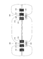
図13のように、送電コイル部210も受電コイル部310も3つのコイルで構成するとする。
そして、m=1の共振モードを選択するように給電コイル240に印加する電流の周波数を選択するとする。すると、送電コイル部210の3つのコイル(221、231、232)には安定した定在波が発生し、磁界ループを図示すると、図13のように送電コイル部210の前段コイル221と受電コイル部310の前段コイル321とで一つの磁界ループを共有し(共振し)、それぞれの後段コイル部230、330でそれぞれの磁界ループを作るようにできる。
このことは、複数の共鳴コイルを配置することによって近傍の磁界を制御したと捉えることができる。
その結果として、送電コイル部210から受電コイル部310への送電効率を背景技術よりも高めることができる。 It is considered that magnetic resonance generated in the powertransmission coil unit 210 and the power reception coil unit 310 can be controlled using such a phenomenon.
As shown in FIG. 13, it is assumed that the powertransmission coil unit 210 and the power reception coil unit 310 are configured by three coils.
Then, it is assumed that the frequency of the current applied to thefeeding coil 240 is selected so as to select the resonance mode of m = 1. Then, stable standing waves are generated in the three coils (221, 231, 232) of the power transmission coil unit 210, and when a magnetic field loop is illustrated, the front coil 221 and the power receiving coil of the power transmission coil unit 210 as illustrated in FIG. It is possible to share (resonate) one magnetic field loop with the pre-stage coil 321 of the part 310 and to make the respective magnetic field loops with the respective post-stage coil parts 230 and 330.
This can be regarded as controlling a nearby magnetic field by arranging a plurality of resonance coils.
As a result, the power transmission efficiency from the powertransmission coil unit 210 to the power reception coil unit 310 can be increased as compared with the background art.
図13のように、送電コイル部210も受電コイル部310も3つのコイルで構成するとする。
そして、m=1の共振モードを選択するように給電コイル240に印加する電流の周波数を選択するとする。すると、送電コイル部210の3つのコイル(221、231、232)には安定した定在波が発生し、磁界ループを図示すると、図13のように送電コイル部210の前段コイル221と受電コイル部310の前段コイル321とで一つの磁界ループを共有し(共振し)、それぞれの後段コイル部230、330でそれぞれの磁界ループを作るようにできる。
このことは、複数の共鳴コイルを配置することによって近傍の磁界を制御したと捉えることができる。
その結果として、送電コイル部210から受電コイル部310への送電効率を背景技術よりも高めることができる。 It is considered that magnetic resonance generated in the power
As shown in FIG. 13, it is assumed that the power
Then, it is assumed that the frequency of the current applied to the
This can be regarded as controlling a nearby magnetic field by arranging a plurality of resonance coils.
As a result, the power transmission efficiency from the power
一方、送電コイル部210も受電コイル部310も3つの共鳴コイルで構成し、単純に、送電コイル部210と受電コイル部310とを近づけ過ぎると、6つの共鳴コイルによる定在波が生じ、結果として6個の共振状態が生じる。
そのため、先にあげた、3つの共鳴コイルにおけるm=1の共振モードが綺麗に生じなくなる。
この場合、必ずしも送電効率を高める構成ではなくなる。
送電コイル部210と受電コイル部310を離していき、各々のコイル部が独立した電磁伝搬構造と見なせる距離になると、3つの共鳴コイルにおけるm=1の共振モードが明らかに生じ、その結果、送電効率が向上する。 On the other hand, both the powertransmission coil unit 210 and the power reception coil unit 310 are configured by three resonance coils. If the power transmission coil unit 210 and the power reception coil unit 310 are simply brought too close to each other, standing waves are generated by the six resonance coils. As a result, six resonance states occur.
Therefore, the above-described resonance mode of m = 1 in the three resonance coils does not occur neatly.
In this case, it is not necessarily the structure which improves power transmission efficiency.
When the powertransmission coil unit 210 and the power reception coil unit 310 are separated from each other and each coil unit reaches a distance that can be regarded as an independent electromagnetic propagation structure, a resonance mode of m = 1 in the three resonance coils is apparently generated. Efficiency is improved.
そのため、先にあげた、3つの共鳴コイルにおけるm=1の共振モードが綺麗に生じなくなる。
この場合、必ずしも送電効率を高める構成ではなくなる。
送電コイル部210と受電コイル部310を離していき、各々のコイル部が独立した電磁伝搬構造と見なせる距離になると、3つの共鳴コイルにおけるm=1の共振モードが明らかに生じ、その結果、送電効率が向上する。 On the other hand, both the power
Therefore, the above-described resonance mode of m = 1 in the three resonance coils does not occur neatly.
In this case, it is not necessarily the structure which improves power transmission efficiency.
When the power
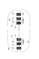
図14のように送受電コイル部210、310をそれぞれ3つの共鳴コイルで構成した場合、送受電コイルともに、3つの共鳴コイルにおけるm=0の共振状態が発生し、すべてのコイルが同位相で電力伝送が行われる磁界共鳴が生じる周波数もある。
しかし、実験によると、先にあげたm=1の共振モードほどの効果は得られていない。 As shown in FIG. 14, when the power transmitting / receiving coil sections 210 and 310 are each constituted by three resonance coils, resonance states of m = 0 in the three resonance coils are generated in both the power transmission / reception coils, and all the coils have the same phase. There is also a frequency at which magnetic field resonance in which power is transmitted occurs.
However, according to the experiment, the effect as the resonance mode of m = 1 mentioned above is not obtained.
しかし、実験によると、先にあげたm=1の共振モードほどの効果は得られていない。 As shown in FIG. 14, when the power transmitting / receiving
However, according to the experiment, the effect as the resonance mode of m = 1 mentioned above is not obtained.
なお、共鳴コイルの数や共鳴コイルの特性が変更されたり、送電コイル部210と受電コイル部310との距離が変わってきたりすれば、最適な磁界共鳴状態が図13の例とは違ってくるのはもちろんである。
しかし、複数の共鳴コイルによって構成される送電コイル部210(または受電コイル部310)に共振状態を作ることで安定した定在波を作り出せること、および、これによって送電コイル部210から受電コイル部310への送電効率を高められることは変わりがない。 If the number of resonance coils and the characteristics of the resonance coils are changed or the distance between the powertransmission coil unit 210 and the power reception coil unit 310 is changed, the optimum magnetic field resonance state differs from the example of FIG. Of course.
However, a stable standing wave can be created by creating a resonance state in the power transmission coil unit 210 (or the power reception coil unit 310) constituted by a plurality of resonance coils, and the powertransmission coil unit 210 can thereby generate a power reception coil unit 310. There will be no change in the efficiency of power transmission.
しかし、複数の共鳴コイルによって構成される送電コイル部210(または受電コイル部310)に共振状態を作ることで安定した定在波を作り出せること、および、これによって送電コイル部210から受電コイル部310への送電効率を高められることは変わりがない。 If the number of resonance coils and the characteristics of the resonance coils are changed or the distance between the power
However, a stable standing wave can be created by creating a resonance state in the power transmission coil unit 210 (or the power reception coil unit 310) constituted by a plurality of resonance coils, and the power
(変形例1)
上記第1実施形態の構成と床面との距離を適切に調整することにより、送電効率のさらなる向上を図ることができる。
図15、図16はそのことを示す測定系説明図と測定結果である。
図15に示すように、コイル周期構造(送電コイル部210、受電コイル部310)と床面800との距離を20cm、もしくは、60cmとする。
図16は、上記二つの場合で送電効率を測定した結果である。
図16より、床面800からの距離を60cmとするよりも、床面800との距離を20cmとした方が、送電距離がある程度離れたところで送電効率が向上していることがわかる。
すなわち、床面800とコイル周期構造(送電コイル部210、受電コイル部310)との距離を巧みに利用することにより、送電効率のさらなる向上を望める。
さらに、床面に限らず、金属板など、電磁波を反射させるか遮蔽する物質を送電効率の向上に巧みに利用してもよい。 (Modification 1)
By appropriately adjusting the distance between the configuration of the first embodiment and the floor surface, it is possible to further improve the power transmission efficiency.
FIGS. 15 and 16 are a measurement system explanatory diagram and measurement results showing this.
As shown in FIG. 15, the distance between the coil periodic structure (the powertransmission coil unit 210 and the power reception coil unit 310) and the floor surface 800 is set to 20 cm or 60 cm.
FIG. 16 shows the results of measuring the power transmission efficiency in the above two cases.
From FIG. 16, it can be seen that when the distance from thefloor 800 is set to 20 cm, the power transmission efficiency is improved at a certain distance from the floor 800, rather than from 60 cm.
That is, it is possible to further improve power transmission efficiency by skillfully utilizing the distance between thefloor surface 800 and the coil periodic structure (the power transmission coil unit 210 and the power reception coil unit 310).
Furthermore, not only the floor surface but also a material that reflects or shields electromagnetic waves, such as a metal plate, may be skillfully used to improve power transmission efficiency.
上記第1実施形態の構成と床面との距離を適切に調整することにより、送電効率のさらなる向上を図ることができる。
図15、図16はそのことを示す測定系説明図と測定結果である。
図15に示すように、コイル周期構造(送電コイル部210、受電コイル部310)と床面800との距離を20cm、もしくは、60cmとする。
図16は、上記二つの場合で送電効率を測定した結果である。
図16より、床面800からの距離を60cmとするよりも、床面800との距離を20cmとした方が、送電距離がある程度離れたところで送電効率が向上していることがわかる。
すなわち、床面800とコイル周期構造(送電コイル部210、受電コイル部310)との距離を巧みに利用することにより、送電効率のさらなる向上を望める。
さらに、床面に限らず、金属板など、電磁波を反射させるか遮蔽する物質を送電効率の向上に巧みに利用してもよい。 (Modification 1)
By appropriately adjusting the distance between the configuration of the first embodiment and the floor surface, it is possible to further improve the power transmission efficiency.
FIGS. 15 and 16 are a measurement system explanatory diagram and measurement results showing this.
As shown in FIG. 15, the distance between the coil periodic structure (the power
FIG. 16 shows the results of measuring the power transmission efficiency in the above two cases.
From FIG. 16, it can be seen that when the distance from the
That is, it is possible to further improve power transmission efficiency by skillfully utilizing the distance between the
Furthermore, not only the floor surface but also a material that reflects or shields electromagnetic waves, such as a metal plate, may be skillfully used to improve power transmission efficiency.
(変形例2)
上記第1実施形態においては、送電コイル部210および受電コイル部310は、それぞれ3つの共鳴コイルで構成されている場合を例示した。
これに対し、例えば、送電コイル部210を構成する共鳴コイルの数を4つ、5つなど、増やしてもよい。
同じように、受電コイル部を構成する共鳴コイルの数を4つ、5つなど、増やしてもよい。 (Modification 2)
In the said 1st Embodiment, the case where the powertransmission coil part 210 and the receiving coil part 310 were each comprised by the three resonance coils was illustrated.
On the other hand, you may increase the number of the resonance coils which comprise the powertransmission coil part 210, such as four and five, for example.
Similarly, you may increase the number of resonance coils which comprise a receiving coil part, such as four and five.
上記第1実施形態においては、送電コイル部210および受電コイル部310は、それぞれ3つの共鳴コイルで構成されている場合を例示した。
これに対し、例えば、送電コイル部210を構成する共鳴コイルの数を4つ、5つなど、増やしてもよい。
同じように、受電コイル部を構成する共鳴コイルの数を4つ、5つなど、増やしてもよい。 (Modification 2)
In the said 1st Embodiment, the case where the power
On the other hand, you may increase the number of the resonance coils which comprise the power
Similarly, you may increase the number of resonance coils which comprise a receiving coil part, such as four and five.
(変形例3)
上記実施形態においては、送電コイル部210においても受電コイル部310においても、給電コイル240(受電コイル340)は前段コイル221(321)のすぐ後ろに配置されていた。
これに対し、給電コイル240(受電コイル340)は、複数並ぶ共鳴コイルの間のどこに配置されていてもよい。
例えば、図17のように7つ以上のコイルが並ぶなかで、前(右)から二つ目と三つ目との間に給電コイル(または受電コイル)を配置してもよい。
この場合、前段コイル部(220)が二つの共鳴コイル221、222で構成され、後段コイル部が3番目以降のコイルで構成されている、と解釈してもよい。 (Modification 3)
In the above embodiment, in both the powertransmission coil unit 210 and the power reception coil unit 310, the power supply coil 240 (power reception coil 340) is disposed immediately behind the front coil 221 (321).
On the other hand, the power feeding coil 240 (power receiving coil 340) may be disposed anywhere between the plurality of resonance coils arranged.
For example, as shown in FIG. 17, a feeding coil (or a receiving coil) may be arranged between the second and third from the front (right) while seven or more coils are arranged.
In this case, it may be interpreted that the front coil part (220) is composed of two resonance coils 221 and 222, and the rear coil part is composed of the third and subsequent coils.
上記実施形態においては、送電コイル部210においても受電コイル部310においても、給電コイル240(受電コイル340)は前段コイル221(321)のすぐ後ろに配置されていた。
これに対し、給電コイル240(受電コイル340)は、複数並ぶ共鳴コイルの間のどこに配置されていてもよい。
例えば、図17のように7つ以上のコイルが並ぶなかで、前(右)から二つ目と三つ目との間に給電コイル(または受電コイル)を配置してもよい。
この場合、前段コイル部(220)が二つの共鳴コイル221、222で構成され、後段コイル部が3番目以降のコイルで構成されている、と解釈してもよい。 (Modification 3)
In the above embodiment, in both the power
On the other hand, the power feeding coil 240 (power receiving coil 340) may be disposed anywhere between the plurality of resonance coils arranged.
For example, as shown in FIG. 17, a feeding coil (or a receiving coil) may be arranged between the second and third from the front (right) while seven or more coils are arranged.
In this case, it may be interpreted that the front coil part (220) is composed of two
(変形例4)
共鳴コイルのインピーダンスが可変であってもよい。
共鳴コイルのインピーダンスを可変にすることにより、図18のように分散曲線をシフトさせることができる。
共鳴コイルのインピーダンスを制御するにあたっては、コイルコアの誘電率または透磁率を制御してもよく、共鳴コイルに可変容量を付加して可変容量の容量値を変化させてもよい。
図19に示すように、給電部にインピーダンス制御部284を設けておく。
このように送電コイル部210の側でコイルインピーダンスを可変とすれば、固定された周波数に対して送電コイル部210に所望の共振状態を作ることができる。
また、図示しないが、受電コイル部310の側でコイルインピーダンスを可変とすれば、受信する周波数に対して受電コイル部310に所望の共振状態を作ることができる。
コイルインピーダンスを変化させるにあたっては、送電コイル部を構成するすべてのコイルのインピーダンスを一斉に同じように変化させてもよく、あるいは、個々のコイルのインピーダンスを個別に変更調整できるようになっていてもよい。
同じように、受電装置についても、すべてのコイルのインピーダンスを一斉に変更してもよく、あるいは、個々のコイルのインピーダンスを個別に変更調整できるようになっていても良い。 (Modification 4)
The impedance of the resonance coil may be variable.
By making the impedance of the resonance coil variable, the dispersion curve can be shifted as shown in FIG.
In controlling the impedance of the resonance coil, the dielectric constant or magnetic permeability of the coil core may be controlled, or a variable capacitance may be added to the resonance coil to change the capacitance value of the variable capacitance.
As shown in FIG. 19, animpedance control unit 284 is provided in the power feeding unit.
As described above, if the coil impedance is variable on the powertransmission coil unit 210 side, a desired resonance state can be created in the power transmission coil unit 210 with respect to the fixed frequency.
Although not shown, if the coil impedance is variable on the power receivingcoil unit 310 side, a desired resonance state can be created in the power receiving coil unit 310 with respect to the received frequency.
When changing the coil impedance, the impedances of all the coils constituting the power transmission coil unit may be changed at the same time, or the impedances of the individual coils may be individually changed and adjusted. Good.
Similarly, with respect to the power receiving apparatus, the impedances of all the coils may be changed at the same time, or the impedances of the individual coils may be individually changed and adjusted.
共鳴コイルのインピーダンスが可変であってもよい。
共鳴コイルのインピーダンスを可変にすることにより、図18のように分散曲線をシフトさせることができる。
共鳴コイルのインピーダンスを制御するにあたっては、コイルコアの誘電率または透磁率を制御してもよく、共鳴コイルに可変容量を付加して可変容量の容量値を変化させてもよい。
図19に示すように、給電部にインピーダンス制御部284を設けておく。
このように送電コイル部210の側でコイルインピーダンスを可変とすれば、固定された周波数に対して送電コイル部210に所望の共振状態を作ることができる。
また、図示しないが、受電コイル部310の側でコイルインピーダンスを可変とすれば、受信する周波数に対して受電コイル部310に所望の共振状態を作ることができる。
コイルインピーダンスを変化させるにあたっては、送電コイル部を構成するすべてのコイルのインピーダンスを一斉に同じように変化させてもよく、あるいは、個々のコイルのインピーダンスを個別に変更調整できるようになっていてもよい。
同じように、受電装置についても、すべてのコイルのインピーダンスを一斉に変更してもよく、あるいは、個々のコイルのインピーダンスを個別に変更調整できるようになっていても良い。 (Modification 4)
The impedance of the resonance coil may be variable.
By making the impedance of the resonance coil variable, the dispersion curve can be shifted as shown in FIG.
In controlling the impedance of the resonance coil, the dielectric constant or magnetic permeability of the coil core may be controlled, or a variable capacitance may be added to the resonance coil to change the capacitance value of the variable capacitance.
As shown in FIG. 19, an
As described above, if the coil impedance is variable on the power
Although not shown, if the coil impedance is variable on the power receiving
When changing the coil impedance, the impedances of all the coils constituting the power transmission coil unit may be changed at the same time, or the impedances of the individual coils may be individually changed and adjusted. Good.
Similarly, with respect to the power receiving apparatus, the impedances of all the coils may be changed at the same time, or the impedances of the individual coils may be individually changed and adjusted.
(変形例5)
上記実施形態においては、共鳴コイルとしてスプリング型のコイルを例示した。
共鳴コイルとしては、例えば、図20Aに示す平面スパイラル状のコイルを用いてもよい。
平面スパイラル状のコイル501は、プリント回路基板に実装できるという利点がある。
すなわち、プリント基板のおもて面または裏面にスパイラルコイル501を一つ実装しておいてもよい。
または、平面スパイラル状のコイルをプリント基板の両面に実装してもよい。
例えば、図20Aの平面スパイラル状のコイル501をプリント基板の表側に実装する。
そして、図20Bのコイル502をプリント基板の裏面に実装する。
図20Bは、プリント基板の裏面に実装されるコイル501を表面側から透視したものである。
このとき、接合点503で表面側コイル501と裏面側コイル502とを導体接続することにより、両面実装として一続きのスパイラル形状を構成することができる。
ここでは表面実装と両面実装との場合を説明したが、多層基板においても各々の層のスパイラル導体と層間を接続する導体とにより、多層基板上で様々なスパイラル導体実装が可能となる。
また、図20A、図20Bでは、矩形であって矩形の各辺が直線的形状であるスパイラルコイルを例示したが、曲線のスパイラルであっても良いことは言うまでもない。 (Modification 5)
In the above embodiment, a spring type coil is exemplified as the resonance coil.
As the resonance coil, for example, a planar spiral coil shown in FIG. 20A may be used.
Theplanar spiral coil 501 has an advantage that it can be mounted on a printed circuit board.
That is, onespiral coil 501 may be mounted on the front surface or the back surface of the printed board.
Alternatively, planar spiral coils may be mounted on both sides of the printed board.
For example, theplanar spiral coil 501 of FIG. 20A is mounted on the front side of the printed board.
Then, thecoil 502 of FIG. 20B is mounted on the back surface of the printed board.
FIG. 20B is a perspective view of thecoil 501 mounted on the back surface of the printed circuit board from the front surface side.
At this time, a continuous spiral shape can be formed as double-sided mounting by conducting conductor connection between thefront side coil 501 and the back side coil 502 at the junction point 503.
Although the case of surface mounting and double-sided mounting has been described here, various types of spiral conductors can be mounted on the multilayer substrate by using the spiral conductors of the respective layers and the conductors connecting the layers.
20A and 20B exemplify a spiral coil having a rectangular shape and each side of the rectangle having a linear shape, it goes without saying that it may be a curved spiral.
上記実施形態においては、共鳴コイルとしてスプリング型のコイルを例示した。
共鳴コイルとしては、例えば、図20Aに示す平面スパイラル状のコイルを用いてもよい。
平面スパイラル状のコイル501は、プリント回路基板に実装できるという利点がある。
すなわち、プリント基板のおもて面または裏面にスパイラルコイル501を一つ実装しておいてもよい。
または、平面スパイラル状のコイルをプリント基板の両面に実装してもよい。
例えば、図20Aの平面スパイラル状のコイル501をプリント基板の表側に実装する。
そして、図20Bのコイル502をプリント基板の裏面に実装する。
図20Bは、プリント基板の裏面に実装されるコイル501を表面側から透視したものである。
このとき、接合点503で表面側コイル501と裏面側コイル502とを導体接続することにより、両面実装として一続きのスパイラル形状を構成することができる。
ここでは表面実装と両面実装との場合を説明したが、多層基板においても各々の層のスパイラル導体と層間を接続する導体とにより、多層基板上で様々なスパイラル導体実装が可能となる。
また、図20A、図20Bでは、矩形であって矩形の各辺が直線的形状であるスパイラルコイルを例示したが、曲線のスパイラルであっても良いことは言うまでもない。 (Modification 5)
In the above embodiment, a spring type coil is exemplified as the resonance coil.
As the resonance coil, for example, a planar spiral coil shown in FIG. 20A may be used.
The
That is, one
Alternatively, planar spiral coils may be mounted on both sides of the printed board.
For example, the
Then, the
FIG. 20B is a perspective view of the
At this time, a continuous spiral shape can be formed as double-sided mounting by conducting conductor connection between the
Although the case of surface mounting and double-sided mounting has been described here, various types of spiral conductors can be mounted on the multilayer substrate by using the spiral conductors of the respective layers and the conductors connecting the layers.
20A and 20B exemplify a spiral coil having a rectangular shape and each side of the rectangle having a linear shape, it goes without saying that it may be a curved spiral.
また、スパイラル状コイルが高誘電体基板に実装されていてもよい。
または、スパイラル状コイルが磁性体上に実装されていてもよい。
これにより、磁束密度を高め、共鳴体(コイル)の小型化を図ることができる。 Moreover, the spiral coil may be mounted on the high dielectric substrate.
Alternatively, a spiral coil may be mounted on the magnetic material.
Thereby, magnetic flux density can be raised and size reduction of a resonance body (coil) can be achieved.
送電装置と受電装置との間は一般的には空気であるが、送電装置と受電装置との間に、水、海水、土、壁があってもよい。
The space between the power transmission device and the power reception device is generally air, but water, seawater, soil, or a wall may be provided between the power transmission device and the power reception device.
複数の送電コイル部(または受電コイル部)を2次元的に配列してもよい。
さらに、例えば図21に示すように、2次元的に配列した複数の送電コイル部(または受電コイル部)を剛性を有する二枚の基板611、612で挟んで、送電コイル部(または受電コイル部)が曲がらないように剛性を持たせてもよい。
または、柔軟性を有する二枚のシートで共鳴コイルを挟んで、送電コイル部または受電コイル部が柔軟に曲がるようにしておいてもよい。 A plurality of power transmission coil units (or power reception coil units) may be two-dimensionally arranged.
Further, for example, as shown in FIG. 21, a plurality of power transmission coil sections (or power reception coil sections) arranged two-dimensionally are sandwiched between two rigid boards 611 and 612, and the power transmission coil section (or power reception coil section) ) May be rigid so that it does not bend.
Alternatively, the power transmission coil unit or the power reception coil unit may be flexibly bent by sandwiching the resonance coil between two sheets having flexibility.
さらに、例えば図21に示すように、2次元的に配列した複数の送電コイル部(または受電コイル部)を剛性を有する二枚の基板611、612で挟んで、送電コイル部(または受電コイル部)が曲がらないように剛性を持たせてもよい。
または、柔軟性を有する二枚のシートで共鳴コイルを挟んで、送電コイル部または受電コイル部が柔軟に曲がるようにしておいてもよい。 A plurality of power transmission coil units (or power reception coil units) may be two-dimensionally arranged.
Further, for example, as shown in FIG. 21, a plurality of power transmission coil sections (or power reception coil sections) arranged two-dimensionally are sandwiched between two
Alternatively, the power transmission coil unit or the power reception coil unit may be flexibly bent by sandwiching the resonance coil between two sheets having flexibility.
本明細書において"周期構造"の用語を用い、送電コイル部(または受電コイル部)が複数の共鳴コイルによる周期構造で構成されている、と表現した。
ここで、周期構造とは、厳密な一定ピッチの配列構造だけに限定解釈されるべきではない。
厳密に一定周期でなくてもよく、本発明の全趣旨からみて送電コイル部(または受電コイル部)をメタマテリアルとして扱える範囲で共鳴コイルの配列ピッチがずれることは許容される。
また、実際の製品とする場合にあっては、製造上の制約も考慮したうえで共鳴コイルの配列ピッチが設計されるので、製造条件に応じて配列周期がずれることは許容される。 In this specification, the term “periodic structure” is used to express that the power transmission coil unit (or the power receiving coil unit) is composed of a periodic structure including a plurality of resonance coils.
Here, the periodic structure should not be construed to be limited to an array structure with a strictly constant pitch.
The period may not be strictly constant, and it is allowed that the arrangement pitch of the resonance coils is deviated within a range in which the power transmission coil unit (or power reception coil unit) can be handled as a metamaterial in view of the whole purpose of the present invention.
Further, in the case of an actual product, the arrangement pitch of the resonance coils is designed in consideration of manufacturing restrictions, so that the arrangement period is allowed to deviate depending on the manufacturing conditions.
受電装置から電力の供給を受ける負荷としては、各種のセンサ、家庭用の電化製品、携帯端末、電気自動車、など、様々な応用製品が挙げられる。
Examples of the load that receives power supply from the power receiving device include various applied products such as various sensors, household appliances, portable terminals, and electric vehicles.
上記実施形態において、一つの送電コイル部は一つのコイル周期構造を備えていた。
同様に、一つの受電コイル部は一つのコイル周期構造を備えていた。
これは、送電コイル部と受電コイル部とで磁界共鳴する周波数が一つであったためであるが、送電コイル部も受電コイル部もそれぞれ複数のコイル周期構造を備えていてもよい。
例えば、一つの送電コイル部(または受電コイル部)に複数のコイル周期構造を持たせるにあたっては、第1コイル周期構造の内側に第2コイル周期構造を設けるようにしてもよい。
このような構成によれば、一の周波数で電力を電送し、他の周波数で信号を電送することができる。 In the said embodiment, one power transmission coil part was equipped with one coil periodic structure.
Similarly, one power receiving coil portion has one coil periodic structure.
This is because the frequency of magnetic field resonance between the power transmission coil unit and the power reception coil unit is one, but both the power transmission coil unit and the power reception coil unit may have a plurality of coil periodic structures.
For example, when a plurality of coil periodic structures are provided in one power transmission coil unit (or power receiving coil unit), a second coil periodic structure may be provided inside the first coil periodic structure.
According to such a configuration, power can be transmitted at one frequency, and a signal can be transmitted at another frequency.
なお、本発明は上記実施形態に限られるものではなく、趣旨を逸脱しない範囲で適宜変更することができる。
Note that the present invention is not limited to the above-described embodiment, and can be appropriately changed without departing from the spirit of the present invention.
以上、実施の形態を参照して本願発明を説明したが、本願発明は上記によって限定されるものではない。本願発明の構成や詳細には、発明のスコープ内で当業者が理解し得る様々な変更をすることができる。
The present invention has been described above with reference to the embodiment, but the present invention is not limited to the above. Various changes that can be understood by those skilled in the art can be made to the configuration and details of the present invention within the scope of the invention.
この出願は、2012年2月29日に出願された日本出願特願2012-043772を基礎とする優先権を主張し、その開示の全てをここに取り込む。
This application claims priority based on Japanese Patent Application No. 2012-043772 filed on February 29, 2012, the entire disclosure of which is incorporated herein.
100・・・電力供給システム、200・・・送電装置、210・・・送電コイル部、220・・・前段コイル部、221・・・前段コイル、230・・・後段コイル部、231・・・第1後段コイル、232・・・第2後段コイル、240・・・給電コイル、280・・・給電部、281・・・電源、282・・・電力印加部、283・・・周波数制御部、284・・・インピーダンス制御部、300・・・受電装置、310・・・受電コイル部、320・・・前段コイル部、321・・・前段コイル、330・・・後段コイル部、331・・・第1後段コイル、332・・・第2後段コイル、340・・・受電コイル、380・・・受電部、401・・・共鳴コイル、401・・・コイル、401h・・・コイル成分、501・・・コイル、502・・・コイル、503・・・接合点、611・・・基板、900・・・負荷。
DESCRIPTION OF SYMBOLS 100 ... Electric power supply system, 200 ... Power transmission apparatus, 210 ... Power transmission coil part, 220 ... Pre-stage coil part, 221 ... Pre-stage coil part, 230 ... Rear stage coil part, 231 ... 1st latter stage coil, 232 ... 2nd latter stage coil, 240 ... feeding coil, 280 ... feeding part, 281 ... power supply, 282 ... power application part, 283 ... frequency control part, 284: Impedance control unit, 300 ... Power receiving device, 310 ... Power receiving coil unit, 320 ... Pre-coil unit, 321 ... Pre-coil, 330 ... Post-coil unit, 331 ... First rear coil, 332 ... Second rear coil, 340 ... Power receiving coil, 380 ... Power receiving unit, 401 ... Resonance coil, 401 ... Coil, 401h ... Coil component, 501 ··coil 502 ... coil, 503 ... junction, 611 ... substrate, 900 ... load.
Claims (18)
- 一次元的に周期構造をなすように配列された複数の共鳴コイルを有し、受電装置と磁界共鳴することによって前記受電装置に電力を送電する送電コイル部と、
前記送電コイル部に電力を供給する給電手段と、を備え、
前記送電コイル部を電磁伝搬波の伝送路とし、この送電コイル手段に電磁伝搬波の定在波を発生させる
ことを特徴とする送電装置。 A power transmission coil unit that has a plurality of resonance coils arranged so as to form a one-dimensional periodic structure, and transmits power to the power reception device by magnetic field resonance with the power reception device;
Power supply means for supplying power to the power transmission coil unit,
The power transmission coil unit is used as a transmission path for electromagnetic propagation waves, and a standing wave of electromagnetic propagation waves is generated in the power transmission coil means. - 請求項1に記載の送電装置において、
前記送電コイル部は、さらに、前記給電手段から給電を受ける給電用ループコイルを有し、
前記給電用ループコイルは、前記共鳴コイル同士の隙間に介在配置されている
ことを特徴とする送電装置。 The power transmission device according to claim 1,
The power transmission coil unit further includes a power supply loop coil that receives power from the power feeding means,
The power feeding device, wherein the power feeding loop coil is disposed in a gap between the resonance coils. - 請求項2に記載の送電装置において、
前記給電用ループコイルは、前記受電装置に最も近い位置にある共鳴コイルと、前記受電装置に二番目に近い位置にある共鳴コイルと、の間に配置されている
ことを特徴とする送電装置。 The power transmission device according to claim 2,
The power feeding device, wherein the power feeding loop coil is disposed between a resonance coil located closest to the power receiving device and a resonance coil located second closest to the power receiving device. - 請求項1から請求項3のいずれかに記載の送電装置において、
前記共鳴コイルの数は3である
ことを特徴とする送電装置。 The power transmission device according to any one of claims 1 to 3,
The number of the resonance coils is three. - 請求項1から請求項4のいずれかに記載の送電装置において、
前記複数の共鳴コイルは、同軸になるように配置されている
ことを特徴とする送電装置。 In the power transmission device according to any one of claims 1 to 4,
The plurality of resonance coils are arranged so as to be coaxial. - 請求項1から請求項5のいずれかに記載の送電装置において、
前記送電コイル部の近傍に電磁波遮蔽物質を配置した
ことを特徴とする送電装置。 In the power transmission device according to any one of claims 1 to 5,
An electromagnetic wave shielding material is disposed in the vicinity of the power transmission coil unit. - 請求項1から請求項6のいずれかに記載の送電装置において、
前記複数の共鳴コイルのうちの一つ以上は、インピーダンスが可変である
ことを特徴とする送電装置。 In the power transmission device according to any one of claims 1 to 6,
One or more of the plurality of resonance coils have variable impedance. - 一次元的に周期構造をなすように配列された複数の共鳴コイルを有し、送電装置と磁界共鳴することによって前記送電装置から電力を受電する受電コイル部と、
前記受電コイル部から電力を受電する受電手段と、を備え、
前記受電コイル部が電磁伝搬波の伝送路となり、前記送電装置との磁界共鳴によってこの受電コイル部に電磁伝搬波の定在波が生じる
ことを特徴とする受電装置。 A plurality of resonance coils arranged so as to form a one-dimensional periodic structure, and a power receiving coil unit that receives power from the power transmission device by magnetic field resonance with the power transmission device;
Power receiving means for receiving power from the power receiving coil unit,
The power receiving device, wherein the power receiving coil portion serves as an electromagnetic propagation wave transmission path, and a standing wave of the electromagnetic propagating wave is generated in the power receiving coil portion by magnetic field resonance with the power transmitting device. - 請求項8に記載の受電装置において、
前記受電コイル部は、さらに、受電用ループコイルを有し、
前記受電用ループコイルは、前記共鳴コイル同士の隙間に介在配置されている
ことを特徴とする受電装置。 The power receiving device according to claim 8, wherein
The power receiving coil portion further includes a power receiving loop coil,
The power receiving loop coil, wherein the power receiving loop coil is disposed in a gap between the resonance coils. - 請求項9に記載の受電装置において、
前記受電用ループコイルは、前記送電装置に最も近い位置にある共鳴コイルと、前記送電装置に二番目に近い位置にある共鳴コイルと、の間に配置されている
ことを特徴とする受電装置。 The power receiving device according to claim 9,
The power receiving loop coil is disposed between a resonance coil located closest to the power transmission device and a resonance coil located second closest to the power transmission device. - 請求項8から請求項10のいずれかに記載の受電装置において、
前記共鳴コイルの数は3である
ことを特徴とする受電装置。 The power receiving device according to any one of claims 8 to 10,
The number of the resonance coils is three. - 請求項8から請求項11のいずれかに記載の受電装置において、
前記複数の共鳴コイルは、同軸になるように配置されている
ことを特徴とする受電装置。 The power receiving device according to any one of claims 8 to 11,
The plurality of resonance coils are arranged so as to be coaxial with each other. - 請求項8から請求項12のいずれかに記載の受電装置において、
前記受電コイル部の近傍に電磁遮蔽物質を配置した
ことを特徴とする受電装置。 The power receiving device according to any one of claims 8 to 12,
A power receiving device, wherein an electromagnetic shielding material is disposed in the vicinity of the power receiving coil section. - 請求項8から請求項13のいずれかに記載の受電装置において、
前記複数の共鳴コイルのうちの一つ以上は、インピーダンスが可変である
ことを特徴とする受電装置。 The power receiving device according to any one of claims 8 to 13,
One or more of the plurality of resonance coils have variable impedance. - 請求項1から請求項7のいずれかに記載の送電装置と、
請求項8から請求項14のいずれかに記載の受電装置と、を備えた電力供給システム。 A power transmission device according to any one of claims 1 to 7,
A power supply system comprising: the power receiving device according to any one of claims 8 to 14. - 請求項15に記載の電力供給システムにおいて、
前記送電装置と前記受電装置との距離は、前記共鳴コイルの直径の2倍以上である
ことを特徴とする電力供給システム。 The power supply system according to claim 15, wherein
A distance between the power transmission device and the power reception device is at least twice the diameter of the resonance coil. - 請求項1から請求項7のいずれかに記載の送電装置を備える電子機器。 An electronic device comprising the power transmission device according to any one of claims 1 to 7.
- 請求項8から請求項14のいずれかに記載の受電装置を備えた電子機器。 An electronic device comprising the power receiving device according to any one of claims 8 to 14.
Applications Claiming Priority (2)
| Application Number | Priority Date | Filing Date | Title |
|---|---|---|---|
| JP2012-043772 | 2012-02-29 | ||
| JP2012043772 | 2012-02-29 |
Publications (1)
| Publication Number | Publication Date |
|---|---|
| WO2013128518A1 true WO2013128518A1 (en) | 2013-09-06 |
Family
ID=49081783
Family Applications (1)
| Application Number | Title | Priority Date | Filing Date |
|---|---|---|---|
| PCT/JP2012/007312 WO2013128518A1 (en) | 2012-02-29 | 2012-11-14 | Power transmitting device, power receiving device, power supply system, and electronic device |
Country Status (2)
| Country | Link |
|---|---|
| JP (1) | JPWO2013128518A1 (en) |
| WO (1) | WO2013128518A1 (en) |
Cited By (1)
| Publication number | Priority date | Publication date | Assignee | Title |
|---|---|---|---|---|
| CN104953723A (en) * | 2015-07-02 | 2015-09-30 | 中国科学院电工研究所 | Device for wireless power transmission |
Citations (4)
| Publication number | Priority date | Publication date | Assignee | Title |
|---|---|---|---|---|
| JP2010130878A (en) * | 2008-12-01 | 2010-06-10 | Toyota Industries Corp | Contactless power transmission system |
| JP2011147271A (en) * | 2010-01-14 | 2011-07-28 | Sony Corp | Power supply device, power receiving device, and wireless power supply system |
| JP2011151989A (en) * | 2010-01-22 | 2011-08-04 | Sony Corp | Wireless power feed device and wireless power feed system |
| JP2011160634A (en) * | 2010-02-04 | 2011-08-18 | Casio Computer Co Ltd | Power transmission system and power transmission device |
-
2012
- 2012-11-14 WO PCT/JP2012/007312 patent/WO2013128518A1/en active Application Filing
- 2012-11-14 JP JP2014501839A patent/JPWO2013128518A1/en active Pending
Patent Citations (4)
| Publication number | Priority date | Publication date | Assignee | Title |
|---|---|---|---|---|
| JP2010130878A (en) * | 2008-12-01 | 2010-06-10 | Toyota Industries Corp | Contactless power transmission system |
| JP2011147271A (en) * | 2010-01-14 | 2011-07-28 | Sony Corp | Power supply device, power receiving device, and wireless power supply system |
| JP2011151989A (en) * | 2010-01-22 | 2011-08-04 | Sony Corp | Wireless power feed device and wireless power feed system |
| JP2011160634A (en) * | 2010-02-04 | 2011-08-18 | Casio Computer Co Ltd | Power transmission system and power transmission device |
Cited By (1)
| Publication number | Priority date | Publication date | Assignee | Title |
|---|---|---|---|---|
| CN104953723A (en) * | 2015-07-02 | 2015-09-30 | 中国科学院电工研究所 | Device for wireless power transmission |
Also Published As
| Publication number | Publication date |
|---|---|
| JPWO2013128518A1 (en) | 2015-07-30 |
Similar Documents
| Publication | Publication Date | Title |
|---|---|---|
| US10158256B2 (en) | Contactless connector system tolerant of position displacement between transmitter coil and receiver coil and having high transmission efficiency | |
| US10957480B2 (en) | Large area power transmitter for wireless power transfer | |
| US9565794B2 (en) | Wireless power transmission system, power transmitting device, and power receiving device | |
| JP6467919B2 (en) | Power transmission device and power transmission method | |
| JP2012182981A (en) | Wireless energy exchange system and method | |
| KR20120087568A (en) | Apparatus and method for wireless power transmission | |
| JP5981202B2 (en) | Power transmission system | |
| US9887681B2 (en) | Power transmission system, transmission apparatus, receiving apparatus, and power transmission method | |
| CN107148710B (en) | Wireless power transfer using stacked resonators | |
| CN106816297B (en) | Wireless power transmission device, power supply device, and power receiving device | |
| JP6270219B2 (en) | Power supply | |
| KR101140338B1 (en) | Resonant coil structure for wireless power transfer | |
| KR101222137B1 (en) | Directional wireless power transmission apparatus using magnetic resonance induction | |
| JP2013099090A (en) | Electromagnetic wave propagation device and power transmission system | |
| WO2013128518A1 (en) | Power transmitting device, power receiving device, power supply system, and electronic device | |
| JP2016076645A (en) | Planar coil | |
| JP5981203B2 (en) | Power transmission system | |
| WO2013108325A1 (en) | Power supply system | |
| WO2018051936A1 (en) | Wireless power supply device and wireless power supply method | |
| WO2014030440A1 (en) | Power supply device | |
| Shi et al. | Parallel strips coupled split ring resonators for a desktop wireless charging system overcoming irregular route restrictions | |
| JP6760806B2 (en) | Wireless power supply | |
| JP2016059146A (en) | Under seawater power supply system | |
| JP5461277B2 (en) | Antenna device, power transmission device, power reception device, and non-contact power transmission system | |
| WO2013108324A1 (en) | Power supply system |
Legal Events
| Date | Code | Title | Description |
|---|---|---|---|
| 121 | Ep: the epo has been informed by wipo that ep was designated in this application |
Ref document number: 12870166 Country of ref document: EP Kind code of ref document: A1 |
|
| ENP | Entry into the national phase |
Ref document number: 2014501839 Country of ref document: JP Kind code of ref document: A |
|
| NENP | Non-entry into the national phase |
Ref country code: DE |
|
| 122 | Ep: pct application non-entry in european phase |
Ref document number: 12870166 Country of ref document: EP Kind code of ref document: A1 |