WO2013125481A1 - 電動リベッター - Google Patents
電動リベッター Download PDFInfo
- Publication number
- WO2013125481A1 WO2013125481A1 PCT/JP2013/053850 JP2013053850W WO2013125481A1 WO 2013125481 A1 WO2013125481 A1 WO 2013125481A1 JP 2013053850 W JP2013053850 W JP 2013053850W WO 2013125481 A1 WO2013125481 A1 WO 2013125481A1
- Authority
- WO
- WIPO (PCT)
- Prior art keywords
- jaw
- pin
- drive
- electric motor
- unit
- Prior art date
Links
Images


Classifications
-
- B—PERFORMING OPERATIONS; TRANSPORTING
- B21—MECHANICAL METAL-WORKING WITHOUT ESSENTIALLY REMOVING MATERIAL; PUNCHING METAL
- B21J—FORGING; HAMMERING; PRESSING METAL; RIVETING; FORGE FURNACES
- B21J15/00—Riveting
- B21J15/10—Riveting machines
- B21J15/30—Particular elements, e.g. supports; Suspension equipment specially adapted for portable riveters
- B21J15/32—Devices for inserting or holding rivets in position with or without feeding arrangements
- B21J15/326—Broken-off mandrel collection
-
- B—PERFORMING OPERATIONS; TRANSPORTING
- B21—MECHANICAL METAL-WORKING WITHOUT ESSENTIALLY REMOVING MATERIAL; PUNCHING METAL
- B21J—FORGING; HAMMERING; PRESSING METAL; RIVETING; FORGE FURNACES
- B21J15/00—Riveting
- B21J15/02—Riveting procedures
- B21J15/04—Riveting hollow rivets mechanically
- B21J15/043—Riveting hollow rivets mechanically by pulling a mandrel
-
- B—PERFORMING OPERATIONS; TRANSPORTING
- B21—MECHANICAL METAL-WORKING WITHOUT ESSENTIALLY REMOVING MATERIAL; PUNCHING METAL
- B21J—FORGING; HAMMERING; PRESSING METAL; RIVETING; FORGE FURNACES
- B21J15/00—Riveting
- B21J15/10—Riveting machines
- B21J15/105—Portable riveters
-
- B—PERFORMING OPERATIONS; TRANSPORTING
- B21—MECHANICAL METAL-WORKING WITHOUT ESSENTIALLY REMOVING MATERIAL; PUNCHING METAL
- B21J—FORGING; HAMMERING; PRESSING METAL; RIVETING; FORGE FURNACES
- B21J15/00—Riveting
- B21J15/10—Riveting machines
- B21J15/16—Drives for riveting machines; Transmission means therefor
- B21J15/26—Drives for riveting machines; Transmission means therefor operated by rotary drive, e.g. by electric motor
-
- Y—GENERAL TAGGING OF NEW TECHNOLOGICAL DEVELOPMENTS; GENERAL TAGGING OF CROSS-SECTIONAL TECHNOLOGIES SPANNING OVER SEVERAL SECTIONS OF THE IPC; TECHNICAL SUBJECTS COVERED BY FORMER USPC CROSS-REFERENCE ART COLLECTIONS [XRACs] AND DIGESTS
- Y10—TECHNICAL SUBJECTS COVERED BY FORMER USPC
- Y10T—TECHNICAL SUBJECTS COVERED BY FORMER US CLASSIFICATION
- Y10T29/00—Metal working
- Y10T29/53—Means to assemble or disassemble
- Y10T29/53709—Overedge assembling means
- Y10T29/53717—Annular work
- Y10T29/53726—Annular work with second workpiece inside annular work one workpiece moved to shape the other
- Y10T29/5373—Annular work with second workpiece inside annular work one workpiece moved to shape the other comprising driver for snap-off-mandrel fastener; e.g., Pop [TM] riveter
- Y10T29/53752—Annular work with second workpiece inside annular work one workpiece moved to shape the other comprising driver for snap-off-mandrel fastener; e.g., Pop [TM] riveter having rotary drive mechanism
Definitions
- the present invention relates to an electric riveter used when riveting two or more members.
- an electric riveter used for riveting two or more members, one using electric power as a power source (hereinafter referred to as an electric riveter) has been provided.
- an electric riveter includes an operating portion for pulling out a pulling pin inserted through the rivet, a driving portion for driving the operating portion, and a housing that houses the operating portion and the driving portion.
- the operating portion is a cylindrical cover portion having a distal end portion and a proximal end portion, and a cylindrical jaw case having a cover portion whose proximal end portion is connected to the housing, and a distal end portion and a proximal end portion.
- a jaw case that is concentrically mounted in the cover part and is movable along the center of the cover part, and a nozzle provided at the tip of the cover part, and is formed with a rivet insertion hole that is concentric with the jaw case.
- a jaw that is built in the tip of the jaw case and that is configured to be able to hold the extraction pin. As a result, the pulling pin inserted into the rivet shaft insertion hole reaches the jaw in the cover portion (jaw case).
- the drive unit includes an electric motor having an output shaft and a drive transmission mechanism that transmits the driving force of the electric motor to the operating unit.
- the drive part transmission mechanism includes a feed screw mechanism that moves the jaw case within the cover part.
- the feed screw mechanism includes a female screw member and a male screw member concentrically screwed with the female screw member.
- Either one of the female screw member and the male screw member of the feed screw mechanism is directly or indirectly connected to the base end portion of the jaw case. Then, either the female screw member or the male screw member of the drive transmission mechanism is connected directly or indirectly concentrically with the output shaft of the electric motor.
- either the female screw member or the male screw member is rotated by receiving the drive of the electric motor. Then, either the female screw member or the male screw member moves in the direction in which the center line of the male screw member extends. Therefore, the jaw case moves in the same direction as either the female screw member or the male screw member by driving the electric motor.
- the jaw housed in the jaw case also moves in the same direction as either the female screw member or the male screw member.
- the housing is a handle housing portion having a first end portion and a second end portion opposite to the first end portion, and a drive housing portion in which the drive portion is housed, and is connected to the first end portion of the handle portion.
- Drive accommodating portion The handle portion is formed such that a center line extending from the first end portion toward the second end portion (or from the second end portion to the first end portion) serves as a gripping center when the operator grips. Yes.
- the handle portion is provided with a trigger switch for switching between power supply to the electric motor and its stop. The trigger switch is disposed within a range that the operator holds in the handle portion.
- the drive accommodating portion of the housing has a feed screw mechanism (female screw member and male screw) so that the shaft centers of the female screw member and the male screw member extend in a direction intersecting with the direction in which the center line (grip center) of the handle portion extends. Member).
- An electric motor is also accommodated in the drive accommodating portion of the housing so that the drive can be transmitted to the feed screw mechanism.
- the base end portion of the cover portion is connected to the drive accommodating portion of the housing so as to be concentric with the accommodated feed screw mechanism. That is, the drive housing portion has a first end portion and a second end portion on the opposite side of the first end portion in a direction intersecting with the direction in which the center line (grip center) of the handle portion extends. And the base end part of the cover part is connected with the 1st end part of the drive accommodating part so that it may become concentric with the accommodated feed screw mechanism.
- the extraction pin collection unit includes a pin collection path having a first opening end and a second opening end opposite to the first opening end, and a collection tank that houses the extraction pin.
- the pin collection path is concentric or substantially concentric with the jaw case and the feed screw mechanism. That is, the pin collection path passes through the male screw member of the feed screw mechanism so as to pass through the center of the jaw case and the feed screw mechanism. And the pin collection
- the electric motor is disposed between the feed screw mechanism of the drive unit and the gripping position of the handle unit in order to open the second opening end of the pin recovery path. That is, in this type of electric riveter, the second opening end of the pin recovery path cannot be opened if the operating portion (feed screw mechanism) and the electric motor are arranged in the same row. Therefore, the electric motor of this type of electric riveter is disposed so that the output shaft is parallel to the feed screw mechanism and is positioned between the feed screw mechanism and the gripping position of the handle portion in the direction in which the gripping center extends. .
- the drive unit of the electric riveter having the above-described configuration further includes a gear mechanism that transmits the driving force of the electric motor to the female screw member.
- the gear mechanism includes a first gear connected to the output shaft of the electric motor, and a second gear attached to either the female screw member or the male screw member. The first gear and the second gear mesh with each other directly or with an intermediate gear.
- the base end portion of the jaw case is connected to the male screw member of the feed screw mechanism.
- the electric riveter having the above-described configuration is configured such that the driving force of the electric motor is transmitted to either the female screw member or the male screw member via the gear mechanism.
- the electric motor is disposed between the feed screw mechanism of the drive unit and the gripping position of the handle unit in order to collect the extraction pin extracted from the rivet.
- the position held by the operator when the rivet is caulked (the area where the trigger switch exists in the handle portion) and the position where the extraction pin is inserted (position of the nozzle)
- the interval is wide. That is, in the electric riveter having the above-described configuration, the gripping position of the handle portion and the insertion position of the extraction pin are separated by the intervention of the electric motor. Therefore, in the electric riveter having the above-described configuration, there is a problem that it is difficult to access a nozzle (a rivet in which a drawing pin is inserted into a rivet insertion hole) at a position to be a fastening target of a member to be rivet-tightened. .
- an object of the present invention is to provide an electric riveter capable of improving the operability while allowing the extraction pin to be extracted when the rivet is caulked to be collected.
- An electric riveter includes an operating part for pulling out a pulling pin inserted into a rivet, a driving part for driving the operating part, a housing that houses each of the operating part and the driving part, and pulling from the rivet.
- a pull-out pin collecting portion for collecting the extracted pull-out pin, and the actuating portion includes a cylindrical cover portion having a distal end portion and a proximal end portion, and a cylindrical jaw having a distal end portion and a proximal end portion
- a case which is concentrically mounted on the cover part and is movable along the direction in which the center line of the cover part extends, and a nozzle provided at the tip of the cover part, and is concentric with the jaw case.
- a drive transmission mechanism that transmits a driving force to the operating portion and moves the jaw case the housing includes a handle portion having a first end portion and a second end portion on the opposite side of the first end portion; And a drive housing portion connected to the first end portion of the handle portion, and the base end portion of the cover portion intersects the grip center of the handle portion.
- the extraction pin collection unit is connected to the drive accommodation unit so as to extend in the direction, and the extraction pin collection unit includes a pin collection path having a first opening end and a second opening end opposite to the first opening end, and a collection unit that accommodates the extraction pin.
- a pin recovery path the first opening end is opened in the jaw while the second opening end is communicated with the internal space of the recovery tank, and the electric motor of the drive unit is arranged in a circumferential direction around the pin recovery path. Thus, it is arranged at a position shifted from the grip center of the handle portion.
- the recovery tank is configured to be detachable from the drive housing portion, and is driven so that the second opening end of the pin recovery path is located above the center portion of the internal space of the recovery tank. It is preferable that it is attached to a storage part.
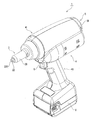
- FIG. 1 is a perspective view of an electric riveter according to an embodiment of the present invention.
- FIG. 2 is a front view of the electric riveter according to the embodiment.
- FIG. 3 is a left side view of the electric riveter according to the embodiment.
- FIG. 4 is a cross-sectional view of the electric riveter according to the embodiment, which is a cross-sectional view taken along line AA of FIG. 5 is a cross-sectional view of the electric riveter according to the embodiment, which is a cross-sectional view taken along the line BB of FIG. 6 is a cross-sectional view of the electric riveter according to the embodiment, which is a cross-sectional view taken along the line CC of FIG.
- the electric riveter pulls out a shaft-shaped pulling pin inserted from the other end side toward one end side with respect to a cylindrical rivet having a large-diameter collar portion formed at one end portion, and the rivet Used to crimp the other end of
- the electric riveter includes an operating unit 2 for pulling out a pulling pin inserted into the rivet, and a driving unit 3 for driving the operating unit 2 (FIG. 4, And a housing 4 in which each of the operating unit 2 and the driving unit 3 is housed.
- the electric riveter 1 includes a drawing pin collection unit 5 for collecting the drawing pin pulled out from the rivet (see FIGS. 3 and 4).
- the housing 4 includes a handle portion 40 having a first end portion and a second end portion on the opposite side of the first end portion, and a drive accommodating portion for accommodating the drive portion 3. 41, and a drive accommodating portion 41 connected to the first end portion of the handle portion 40.
- the operating portion 2 is a cylindrical cover portion 20 having a distal end portion and a proximal end portion, and a tubular cover whose proximal end portion is coupled to the housing 4.
- a cylindrical jaw case 21 having a portion 20, a distal end portion and a proximal end portion, concentrically housed in the cover portion 20, and movable along the center line of the cover portion 20, and a cover
- a nozzle 22 provided at the distal end of the portion 20, which is formed with a rivet insertion hole 220 concentric with the jaw case 21, and a jaw 23 provided in the distal end of the jaw case 21, And a jaw 23 configured to be able to sandwich a pin.
- the operating unit 2 is a cylindrical jaw biasing body 24 having a first end and a second end opposite to the first end, and the first end is A jaw biasing body 24 abutted on the jaw 23 and a biasing spring 25 for biasing the second end of the jaw biasing body 24 toward the jaw 23 are further provided.
- the base end portion of the cover portion 20 is connected to the drive housing portion 41 so that the cover portion 20 extends in a direction intersecting with the gripping center of the handle portion 40.
- the jaw case 21 is concentric with the cover part 20 as described above. Therefore, the jaw case 21 moves along the direction in which the center line (grip center) of the cover portion 20 extends while the outer peripheral surface is guided by the inner peripheral surface of the cover portion 20. That is, the jaw case 21 moves in a direction intersecting with the center line of the handle portion 40.
- the inner peripheral surface of the tip portion of the jaw case 21 (the portion located on the tip portion side of the cover portion 20) is configured with a tapered surface that is tapered toward the opening on the tip portion side. Furthermore, the jaw case 21 is concentrically connected to a male screw member 310b (to be described later) of the drive unit 3 at the base end.
- the rivet shaft insertion hole 220 of the nozzle 22 is continuous inside the jaw 23.
- the extraction pin inserted through the rivet shaft insertion hole 220 of the nozzle 22 reaches the jaw 23.
- the nozzle 22 further includes a jaw contact portion 221 that protrudes into the cover portion 20 and is configured to be able to contact the tip end portion of the jaw 23.
- the jaw 23 is provided such that a through hole 230 set to a diameter slightly smaller than the outer diameter of the extraction pin is concentric with the cover portion 20.
- the jaw 23 includes a plurality of divided bodies 231 and 231 obtained by dividing the truncated cone along the direction in which the center line of the cover portion 20 extends (in this embodiment, divided into two).
- the jaw 23 is housed in the jaw case 21 as described above. Therefore, each of the pair of divided bodies 231 and 231 constituting the jaw 23 moves along the direction in which the center line of the cover portion 20 extends while the outer peripheral surface is guided by the inner peripheral surface of the jaw case 21. Therefore, the jaw 23 is configured such that the adjacent divided bodies 231 and 231 come into contact with each other as the jaw 23 moves along the direction in which the center line of the cover portion 20 extends.
- the jaw biasing body 24 is disposed in the jaw case 21 so as to be concentric with the jaw 23. Therefore, the jaw biasing body 24 is disposed so as to be concentric with the jaw case 21 and the cover portion 20.
- the space inside the jaw urging body 24 is continuous with the through hole 230 of the jaw 23. Further, the jaw biasing body 24 is configured to be movable along the direction in which the center line of the cover portion 20 extends.
- a coil spring is employed as the urging spring 25, and is provided between a male screw member 310b of the drive unit 3 and a jaw urging body 24 described later. Therefore, when the jaw case 21 moves to one side (the side where the drive unit 3 is disposed) in the direction in which the center line of the cover portion 20 extends, the jaw 23 is positioned relative to the jaw case 21 by the biasing of the biasing spring 25. However, the pair of divided bodies 231 and 231 approach each other and pinch the extraction pin while changing to the tip side of the jaw case 21. Further, when the jaw case 21 moves to the other side in the direction in which the center line of the cover portion 20 extends (opposite the side where the driving portion 3 is disposed), the jaw 23 contacts the jaw contact portion 221 of the nozzle 22. As a result, the position relative to the jaw case 21 changes toward the base end side of the jaw case 21 and is separated from each other to release the pinching of the extraction pin.
- the drive unit 3 includes an electric motor 30 having an output shaft 300, a drive transmission mechanism 31 that transmits the driving force of the electric motor 30 to the operating unit 2, and moves the jaw case 21. It has.
- the electric motor 30 is driven by power supplied from a power source V provided at the second end of the handle portion 40. Further, when the electric motor 30 is driven, the output shaft 300 is configured to rotate around its own axis (see FIG. 5).
- the electric motor 30 is arranged so that the output shaft 300 is parallel to the feed screw mechanism 310.
- the electric motor 30 is disposed at a position shifted from the grip center of the handle portion 40 in the circumferential direction around the center line of the cover portion 20 (in the circumferential direction around the pin collection path described later). That is, the electric motor 30 is disposed at a position shifted from between the gripping position of the handle portion 40 and the feed screw mechanism 310 of the drive portion 3 in the circumferential direction around the center line of the cover portion 20. More specifically, the electric motor 30 is within a range of 1 to 90 degrees, more preferably 25 to 45 degrees from the position of the grip center of the handle section 40 in the circumferential direction around the center line of the cover section 20. It is arranged at the position displaced by. In the present embodiment, the electric motor 30 is disposed at a position displaced by 36 degrees from the position of the grip center of the handle portion 40 in the circumferential direction around the center line of the cover portion 20.
- the drive transmission mechanism 31 includes a feed screw mechanism 310 that moves the jaw case 21 within the cover portion 20 (see FIG. 4).
- the feed screw mechanism 310 includes a cylindrical female screw member 310a and a male screw member 310b that is concentrically screwed with the female screw member 310a.
- the female screw member 310a has a screw hole formed in the inner periphery.
- the female screw member 310 a is indirectly connected to the output shaft 300 of the electric motor 30.
- the male screw member 310b is long in one direction.
- the male screw member 310b has a first end in the longitudinal direction and a second end opposite to the first end.
- the first end portion of the male screw member 310 b is directly concentrically connected to the proximal end portion of the jaw case 21.
- a male screw portion is formed at the center of the male screw member 310b in the longitudinal direction.
- the male screw member 310b is provided with a communication hole 310c that extends straight from the first end to the second end.
- the drive transmission mechanism 31 is configured such that the male screw member 310b moves along the direction in which the center line of the male screw member 310b extends as the female screw member 310a rotates.
- a spiral groove is formed on the inner peripheral surface of the female screw member 310a, and a spiral groove is formed on the outer peripheral surface at the center in the longitudinal direction of the male screw member 310b.
- a plurality of ball members are arranged between the groove of the female screw member 310a and the groove of the male screw member 310b. That is, the feed screw mechanism 310 is configured by a ball screw in which a male screw member 310b is screwed to a female screw member 310a via a ball.
- the drive unit 3 includes a gear mechanism 311 that transmits the driving force of the electric motor 30 to the female screw member 310a.
- the drive unit 3 further includes a planetary gear mechanism 312 that transmits the drive of the electric motor 30 to the gear mechanism 311.
- the gear mechanism 311 includes a first gear 311a connected to a planetary gear mechanism 312 (a support plate described later) (see FIG. 6), and a second gear 311b attached to the female screw member 310a.
- the second gear 311b is provided on the outer periphery of the female screw member 310a, and is formed concentrically with the female screw member 310a.
- the first gear 311a and the second gear 311b are directly meshed with each other.
- the planetary gear mechanism 312 includes a sun gear 312 a concentrically connected to the output shaft 300 of the electric motor 30 and a plurality of planetary gears 312 b, 312 b.
- a sun gear 312 a concentrically connected to the output shaft 300 of the electric motor 30 and a plurality of planetary gears 312 b, 312 b.
- three planetary gears 312b, 312b,..., An internal gear 312c surrounding the plurality of planetary gears 312b, 312b,. are provided with a support plate (not shown) that rotatably supports each of.
- the support plate is formed in a disc shape.
- a first gear 311a is concentrically connected to one surface of the support plate.
- a plurality of planetary gears 312b, 312b,... are arranged on the other surface of the support plate at predetermined intervals in the circumferential direction around the center of the support plate.
- the support plate is arranged concentrically with the sun gear 312a by engaging the plurality of planetary gears 312b, 312b... And the sun gear 312a.
- the sun gear 312a (the output shaft 300 of the electric motor 30) and the first gear 311a are arranged concentrically.
- each of the planetary gears 312b, 312b,... rotates around its own axis, while the output shaft 300 (sun gear) of the electric motor 30 rotates. 312a) Move around.
- the support plate rotates concentrically with the output shaft 300 of the electric motor 30.
- the first gear 311a rotates together with the support plate to rotate the female screw member 310a.
- the plurality of planetary gears 312b, 312b,... Can rotate the first gear 311a with a large torque.
- the base end portion of the cover portion 20 is connected to the drive accommodating portion 41 of the housing 4 so as to be concentric with the accommodated feed screw mechanism 310. That is, the drive accommodating portion 41 has a first end portion and a second end portion on the opposite side of the first end portion in a direction intersecting with the direction in which the center line (grip center) of the handle portion 40 extends. And the base end part of the said cover part 20 is connected with the 1st one end part of the drive accommodating part 41 so that the cover part 20 may become concentric with the feed screw mechanism 310.
- the extraction pin collection unit 5 includes a pin collection path 50 having a first opening end and a second opening end opposite to the first opening end, and a collection tank 51 that accommodates the extraction pin.
- the extraction pin collection unit 5 further includes a collection pipe 52 that is long in one direction and that constitutes a pin collection path.
- the pin collection path 50 is configured to be elongated along the direction in which the center line of the cover portion 20 extends. And the pin collection
- the pin collection path 50 includes the through hole 230 of the jaw 23, the inside of the jaw urging body 24 (the inside of the urging spring 25), the communication hole 310c of the male screw member 310b, and the extraction pin collecting portion 5.
- Each of the insides of the recovery pipe 52 is formed.
- the collection tank 51 is configured to be attachable to and detachable from the drive housing portion 41. Further, the recovery tank 51 is attached to the drive accommodating portion 41 so that the second opening end of the pin recovery path 50 is positioned above the center portion of the internal space D. In addition, the collection tank 51 is formed in a bottomed cylindrical shape, and the opening side is configured to be detachable from the second end portion of the drive accommodating portion 41 of the housing 4.
- the collection tank 51 is arranged at a position shifted from the gripping center of the handle portion 40 in the circumferential direction around the center line of the cover portion 20 and at a position facing the electric motor 30. That is, the collection tank 51 is disposed at a position that is substantially symmetric with the electric motor 30 with respect to the center line of the handle portion 40 as seen from the direction in which the center line of the cover portion 20 extends.
- the recovery pipe 52 has a first end in the longitudinal direction and a second end opposite to the first end. Moreover, the 1st end part of the collection
- recovery pipe 52 is connected concentrically with the 2nd end part in the longitudinal direction of the external thread member 310b. The second end of the recovery pipe 52 is configured to extend to the outside of the drive housing unit 40. That is, the recovery pipe 52 is inserted into the drive housing portion 41.
- the electric riveter 1 further includes a trigger switch 6 provided on the first end portion side of the handle portion 40.
- the trigger switch 6 is configured to be switchable between a state where power is supplied from the power source V to the electric motor 30 and a state where power supply from the power source V to the electric motor 30 is stopped by switching between ON and OFF. ing.
- the electric riveter 1 according to the present embodiment is as described above. Next, the operation of the electric riveter 1 having the above-described configuration will be described.
- the position of the rivet shaft insertion hole 220 of the nozzle 22 corresponds to the position of the extraction pin inserted into the rivet so that the extraction pin inserted through the rivet is inserted into the rivet shaft insertion hole 220 of the nozzle 22. Work is done. In the electric riveter 1, when the extraction pin is inserted into the rivet shaft insertion hole 220 of the nozzle 22, the extraction pin reaches the through hole 230 of the jaw 23.
- the jaw case 21 moves from the distal end side of the cover portion 30 to the proximal end side of the cover portion 30 along the direction in which the center line of the cover portion 20 extends in conjunction with the male screw member 310b. Moving. In such a state, the jaw 23 is in a state of being urged by the distal end portion of the cover portion 20. Therefore, the jaw case 21 starts to move together with the jaw case 21 after moving by a predetermined amount.
- the urging force of the urging spring 25 changes the position with respect to the jaw 23 toward the tip end side of the jaw case 21 so that the extraction pin is clamped.
- the jaw 23 clamps the pull-out pin, and from the distal end side of the cover portion 30 to the proximal end side of the cover portion 30 along the direction in which the center line of the cover portion 20 extends. Move (pulled). Then, after the jaw 23 holding the extraction pin starts to be pulled, the extraction pin is pulled out from the rivet (the rivet is caulked).
- the jaw 23 when the jaw 23 returns to the front end side of the cover portion 30 (when the jaw 23 returns to the origin position where the extraction pin can be clamped), the jaw 23 comes into contact with the nozzle 22 and holds the extraction pin extracted from the rivet. To release. Then, the extraction pin extracted from the rivet is guided to the pin recovery path 50 and accommodated in the internal space D of the recovery tank 51.
- the electric motor 30 is disposed at a position shifted from the gripping center of the handle portion 40 in the circumferential direction around the direction in which the center line of the cover portion 20 extends. For this reason, the electric motor 30 is not interposed between the grip position of the handle portion 40 and the feed screw mechanism 310 of the drive portion 3. For this reason, the gripping position of the handle portion 40 and the position where the extraction pin is inserted (position of the rivet shaft insertion hole 220 of the nozzle 22) are close to each other.
- the nozzle 22 (a rivet having a drawing pin inserted into the rivet insertion hole 220) at a position to be a fastening target of a member to be rivet fastened. Therefore, it is possible to obtain an excellent effect that operability can be improved while making it possible to collect the extraction pin that is extracted when the rivet is caulked.
- the electric motor 30 and the collection tank 51 are arranged at positions that are substantially symmetrical with respect to the center line of the handle portion 40, and the first gear 311a is a planetary gear. It is connected to the output shaft 300 of the electric motor 30 via a gear mechanism 312.
- the speed reduction mechanism in the drive housing portion 41 is the planetary gear mechanism 312
- the space in the drive housing portion 41 occupied by the principle mechanism is reduced. Therefore, the dimension in the direction in which the pin collection path 50 extends can be shortened.
- the extraction pin can be efficiently extracted from the rivet. Therefore, the gripping position of the handle portion 40 and the position where the pull-out pin is inserted are closer to each other, and the operability can be further improved.
- the recovery tank 51 is attached to the drive accommodating portion 41 so that the other end portion of the recovery pipe 52 is positioned above the center portion of the internal space D of the recovery tank 51, the internal space D of the recovery tank It is possible to prevent the withdrawal pin collected inside from blocking the other end side of the collection pipe 52. Therefore, riveting can be continuously performed without frequently performing the work of discarding the pull-out pins. Therefore, the collection tank 51 can be detached from the drive housing portion 41 and the extraction pin accommodated in the internal space D of the collection tank can be discarded.
- the electric motor 30 is disposed at a position where the electric motor 30 is displaced by 36 degrees from the position of the gripping center of the handle portion 40 in the circumferential direction around the center line of the cover portion 20, but is not limited thereto. It is not something.
- the jaw 23 was comprised by the two division bodies 231,231, it is not limited to this,
- the jaw 23 is comprised by three or more division bodies 231,231 .... It may be configured.
- the feed screw mechanism 310 has the male screw member 310 b concentrically connected to the jaw case 21, but is not limited thereto.
- the female screw member 310 a is connected to the jaw case 21. It can also be connected concentrically.
- the male screw member 310 b needs to be directly or indirectly connected to the output shaft 300 of the electric motor 30.
- the 1st gearwheel 311a and the 2nd gearwheel 311b were meshing directly, it is not limited to this,
- the 1st gearwheel 311a and the 2nd gearwheel 311b May be engaged via an intermediate gear.
- the feed screw mechanism 310 was comprised with the ball screw by which the external thread member 310b was screwed together by the internal thread member 310a via the ball
- the female screw member 311a and the male screw member 310b may be directly screwed together.
- the gear mechanism 311 is connected to the output shaft 300 of the electric motor 30 via the planetary gear mechanism 312, but the present invention is not limited to this.
- the gear mechanism 311 is an electric motor. It may be directly connected to the 30 output shafts 300.
- Feed screw mechanism 310a ... Female screw member, 310b ... Male screw member, 310c ... Communication hole, 311 ... gear mechanism, 311a ... first gear, 311b ... second gear, 312 ... planetary gear mechanism, 312a ... sun gear, 312b ... planetary gear, 312c ... internal gear, D ... recovery The internal space of the tank, V ... power
Abstract
リベットから引抜ピンを引き抜く作動部を駆動する駆動部を内装するハウジングと、引抜ピンを回収する引抜ピン回収部とを備え、作動部は、基端部がハウジングに連結されるカバー部と、カバー部の先端部に設けられるノズルと、カバー部内のジョーとを備え、駆動部は、作動部を駆動させる電動モータを備え、ハウジングは、棒状のハンドル部に接続される駆動収容部を有し、電動モータは、カバー部の中心線に沿って延びる軸線回りでハンドル部の把持中心からずれた位置に配置される。
Description
本発明は、二つ以上の部材をリベット締めする際に用いられる電動リベッターに関する。
従来から、二つ以上の部材をリベット締めする際に用いられるリベッターとして、電力を動力源とするもの(以下、電動リベッターという)が提供されている。かかる電動リベッターは、リベットに挿通された引抜ピンを引き抜くための作動部と、作動部を駆動するための駆動部と、作動部及び駆動部を内装するハウジングとを備える。
作動部は、先端部と基端部とを有する筒状のカバー部であって、基端部がハウジングに連結されるカバー部と、先端部と基端部とを有する筒状のジョーケースであって、カバー部に同心で内装され、カバー部の中心に沿って移動可能なジョーケースと、カバー部の先端部に設けられるノズルであって、ジョーケースと同心をなすリベット挿通穴の形成されたノズルと、ジョーケースの先端部に内装されるジョーであって、引抜ピンを挟持可能に構成されたジョーとを備える。これにより、作動部は、リベット軸挿通孔に挿通された引抜ピンがカバー部(ジョーケース)内のジョーに到達するようになっている。
駆動部は、出力軸を有する電動モータと、電動モータの駆動力を作動部に伝達する駆動伝達機構とを備える。駆動部伝達機構は、ジョーケースをカバー部内で移動させる送りネジ機構を備える。送りネジ機構は、雌ネジ部材と、雌ネジ部材に対して同心で螺合される雄ネジ部材とを備える。
送りネジ機構の雌ネジ部材又は雄ネジ部材の何れか一方は、ジョーケースの基端部に直接的又は間接的に連結される。そして、駆動伝達機構の雌ネジ部材又は雄ネジ部材の何れか他方は、電動モータの出力軸に対して同心をなして直接的又は間接的に連結される。これにより、駆動伝達機構では、雌ネジ部材又は雄ネジ部材の何れか他方が電動モータの駆動を受けて回転する。そして、雌ネジ部材又は雄ネジ部材の何れか一方が雄ネジ部材の中心線の延びる方向に移動する。従って、ジョーケースは、電動モータの駆動により、雌ネジ部材又は雄ネジ部材の何れか一方と同方向に移動するようになっている。また、ジョーケースに内装されたジョーも同様に、雌ネジ部材又は雄ネジ部材の何れか一方と同方向に移動するようになっている。
ハウジングは、第一端部と該第一端部の反対側の第二端部とを有するハンドル部と、駆動部が収容される駆動収容部であって、ハンドル部の第一端部に接続された駆動収容部とを有する。ハンドル部は、第一端部から第二端部(又は、第二端部から第一端部)に向けて延びる中心線が、作業者が把持する際の把持中心となるように形成されている。ハンドル部には、電動モータに対する電力供給とその停止とを切り替えるためのトリガースイッチが設けられている。トリガースイッチは、ハンドル部における作業者が把持する範囲内に配置されている。
ハウジングの駆動収容部には、雌ネジ部材及び雄ネジ部材の軸心がハンドル部の中心線(把持中心)の延びる方向と交差する方向に延びるように、送りネジ機構(雌ネジ部材及び雄ネジ部材)が収容される。また、ハウジングの駆動収容部には、送りネジ機構に駆動を伝達できるように電動モータも収容される。
そして、ハウジングの駆動収容部には、収容した送りネジ機構と同心になるようにカバー部の基端部が連結されている。すなわち、駆動収容部は、ハンドル部の中心線(把持中心)の延びる方向と交差する方向に第一端部と該第一端部の反対側の第二端部とを有する。そして、カバー部の基端部は、収容した送りネジ機構と同心になるように、駆動収容部の第一端部に連結されている。
この種の電動リベッターでは、リベットをかしめるにあたり、作業者がリベットに挿通された引抜ピンをリベット軸挿通孔に挿通した上でトリガースイッチを操作する。これにより、送りネジ機構が電動モータから駆動を受ける。そして、引抜ピンを挟持したジョーがカバー部の先端部側からカバー部の基端部側に移動する。これに伴い、リベットがかしめられ、該リベットから引抜ピンが引き抜かれる(特許文献1参照)。
ところで、リベットをかしめる度に、該リベットから引き抜かれた引抜ピンを手作業で取り出す作業は煩雑であるとして、リベットから引き抜かれた引抜ピンを連続的に回収する引抜ピン回収部を備えた電動リベッターが提供されている(特許文献2参照)。かかる電動リベッターにおいて、引抜ピン回収部は、第一開口端とその反対側の第二開口端とを有するピン回収経路と、引抜ピンを収容する回収タンクとを備える。
ピン回収経路は、ジョーケース及び送りネジ機構と同心又は略同心をなしている。すなわち、ピン回収経路は、ジョーケース及び送りネジ機構の中心を通るように、送りネジ機構の雄ネジ部材を貫通している。そして、ピン回収経路は、第一開口端をジョー内で開放させ、第二開口端を駆動収容部の第二端部内で開放させている。これに伴い、回収タンクは、駆動収容部の第二端部に連結され、回収タンクの内部空間をピン回収経路の第二開口端と連通させている。
これに伴い、この種の電動リベッターは、ピン回収経路の第二開口端を開放させるために、電動モータが駆動部の送りネジ機構とハンドル部の把持位置との間に配置されている。すなわち、この種の電動リベッターでは、作動部(送りネジ機構)と電動モータを同列に配置するとピン回収路の第二開口端を開放させることができない。そのため、この種の電動リベッターの電動モータは、出力軸が送りネジ機構と平行になり且つ把持中心の伸びる方向における送りネジ機構とハンドル部の把持位置との間に位置するように配置されている。
また、上記構成の電動リベッターの駆動部は、電動モータの駆動力を雌ネジ部材に伝達する歯車機構をさらに備えている。歯車機構は、電動モータの出力軸に連結される第一歯車と、雌ネジ部材又は雄ネジ部材の何れか他方に取り付けられる第二歯車とを備える。なお、第一歯車と第二歯車とは、直接噛合するか中間歯車を介して噛合する。
そして、上記構成の電動リベッターでは、ジョーケースの基端部が送りネジ機構の雄ネジ部材に連結されている。これにより、上記構成の電動リベッターは、電動モータの駆動力が歯車機構を介して雌ネジ部材又は雄ネジ部材の何れか一方に伝達されるように構成されている。
そのため、電動モータに連動して雌ネジ部材又は雄ネジ部材の何れか他方が回転すると、雌ネジ部材又は雄ネジ部材の何れか一方とともにジョーが移動する。これにより、リベットがかしめられた上で、該リベットから引抜ピンが引き抜かれる。そして、ジョーが引抜ピンの挟持を解除すると、該引抜ピンがピン回収経路を通って回収タンクに回収される。従って、上記構成の電動リベッターでは、リベットをかしめる度に、引抜ピンを取り出す作業を行うことなく、複数のリベットを連続してかしめることができるとされている。
ところで、上記構成の電動リベッターは、上述のように、リベットから引き抜かれた引抜ピンを回収すべく、電動モータが駆動部の送りネジ機構とハンドル部の把持位置との間に配置されている。
これに伴い、上記構成の電動リベッターでは、リベットをかしめる際に作業者が把持する位置(ハンドル部におけるトリガースイッチの存在する領域)と、引抜ピンが挿通される位置(ノズルの位置)との間隔が広くなっている。すなわち、上記構成の電動リベッターでは、電動モータの介在により、ハンドル部の把持位置と引抜ピンの挿通位置とが離れた位置になる。そのため、上記構成の電動リベッターでは、リベット締めの対象となる部材の締結対象となる位置に、ノズル(リベット挿通孔に引抜ピンを挿通させたリベット)をアクセスさせることが困難であるという問題がある。
そこで、本発明は、斯かる実情に鑑み、リベットをかしめる際に引き抜かれる引抜ピンを回収可能とした上で、操作性を向上させることのできる電動リベッターを提供することを課題とする。
本発明に係る電動リベッターは、リベットに挿通された引抜ピンを引き抜くための作動部と、作動部を駆動するための駆動部と、作動部及び駆動部のそれぞれを内装するハウジングと、リベットから引き抜かれた引抜ピンを回収するための引抜ピン回収部とを備え、 作動部は、先端部と基端部とを有する筒状のカバー部と、先端部と基端部とを有する筒状のジョーケースであって、カバー部に同心で内装され、カバー部の中心線の延びる方向に沿って移動可能なジョーケースと、カバー部の先端部に設けられるノズルであって、ジョーケースと同心をなすリベット挿通穴の形成されたノズルと、ジョーケースの先端部に内装されるジョーであって、引抜ピンを挟持可能に構成されたジョーとを備え、駆動部は、電動モータと、電動モータの駆動力を作動部に伝達し、ジョーケースを移動させる駆動伝達機構とを備え、ハウジングは、第一端部と該第一端部の反対側の第二端部とを有するハンドル部と、駆動部を収容する駆動収容部であって、ハンドル部の第一端部に接続された駆動収容部とを有し、カバー部の基端部は、当該カバー部がハンドル部の把持中心と交差する方向に延びるように駆動収容部に連結され、引抜ピン回収部は、第一開口端と該第一開口端の反対側の第二開口端とを有するピン回収経路と、引抜ピンを収容する回収タンクとを備え、ピン回収経路は、第一開口端をジョー内で開放させる一方で第二開口端を回収タンクの内部空間に連通させ、駆動部の電動モータは、ピン回収経路回りの周方向でハンドル部の把持中心からずれた位置に配置される。
また、本発明の一態様として、回収タンクは、駆動収容部に着脱可能に構成され、ピン回収経路の第二開口端が該回収タンクの内部空間の中心部よりも上方側に位置するよう駆動収容部に取り付けられることが好ましい。
以下、本発明の一実施形態に係る電動リベッターについて、添付図面を参照しつつ説明を行う。
本実施形態に係る電動リベッターは、一端部に大径の鍔部が形成された筒状のリベットに対して他端側から一端側に向けて挿通された軸状の引抜ピンを引き抜いて前記リベットの他端部をかしめるために用いられる。
本実施形態に係る電動リベッターは、図1から図5に示す如く、リベットに挿通された引抜ピンを引き抜くための作動部2と、作動部2を駆動するための駆動部3と(図4、及び図5参照)、作動部2と駆動部3とのそれぞれを内装するハウジング4とを備えている。また、電動リベッター1は、リベットから引き抜かれた引抜ピンを回収するための引抜ピン回収部5を備えている(図3、及び図4参照)。
そして、本実施形態に係る電動リベッター1においてハウジング4は、第一端部と該第一端部の反対側の第二端部とを有するハンドル部40と、駆動部3を収容する駆動収容部41であって、ハンドル部40の第一端部に接続された駆動収容部41とを備えている。
具体的に説明すると、作動部2は、図4に示す如く、先端部と基端部とを有する筒状のカバー部20であって、基端部がハウジング4に連結される筒状のカバー部20と、先端部と基端部とを有する筒状のジョーケース21であって、カバー部20に同心で内装され、カバー部20の中心線に沿って移動可能なジョーケース21と、カバー部20の先端部に設けられるノズル22であって、ジョーケース21と同心をなすリベット挿通孔220の形成されたノズル22と、ジョーケース21の先端部に内装されるジョー23であって、引抜ピンを挟持可能に構成されたジョー23とを備えている。また、本実施形態に係る作動部2は、第一端部と該第一端部の反対側の第二端部とを有する筒状のジョー付勢体24であって、第一端部をジョー23に当接させたジョー付勢体24と、該ジョー付勢体24の第二端部をジョー23に向けて付勢する付勢バネ25とをさらに備えている。
カバー部20の基端部は、当該カバー部20がハンドル部40の把持中心と交差する方向に延びるように駆動収容部41に連結されている。
ジョーケース21は、上述のように、カバー部20と同心で内装されている。そのため、ジョーケース21は、外周面がカバー部20の内周面に案内されつつ、カバー部20の中心線(把持中心)が延びる方向に沿って移動するようになっている。すなわち、ジョーケース21は、ハンドル部40の中心線と交差する方向に移動するようになっている。
また、ジョーケース21の先端部(カバー部20の先端部側に位置する部分)の内周面は、先端部側の開口に向けて先細りしたテーパー面で構成されている。さらに、ジョーケース21は、基端部が駆動部3の後述する雄ネジ部材310bと同心で連結されている。
ノズル22のリベット軸挿通孔220は、ジョー23の内部に連続している。これにより、電動リベッター1は、ノズル22のリベット軸挿通孔220に挿通された引抜ピンがジョー23に到達するようになっている。そして、ノズル22は、カバー部20の内部に突出してジョー23の先端部と当接可能に構成されるジョー当接部221をさらに備えている。
ジョー23は、引抜ピンの外径よりもやや小さな径に設定された貫通孔230がカバー部20と同心となるように設けられている。また、ジョー23は、截頭円錐体をカバー部20の中心線の延びる方向に沿って分割(本実施形態では、二分割)した複数の分割体231,231で構成されている。
ジョー23は、上述のように、ジョーケース21に内装されている。そのため、ジョー23を構成する一対の分割体231,231のそれぞれは、外周面がジョーケース21の内周面に案内されつつカバー部20の中心線の延びる方向に沿って移動することになる。そのため、ジョー23は、カバー部20の中心線の延びる方向に沿って移動するに伴い、隣り合う分割体231,231同士が接離するように構成されている。
ジョー付勢体24は、ジョー23と同心となるようにジョーケース21内に配置されている。そのため、ジョー付勢体24は、ジョーケース21、及びカバー部20とも同心となるように配置されている。また、ジョー付勢体24の内部の空間は、ジョー23の貫通孔230と連続している。さらに、ジョー付勢体24は、カバー部20の中心線の延びる方向に沿って移動可能に構成されている。
付勢バネ25には、コイルバネが採用されており、後述する駆動部3の雄ネジ部材310bとジョー付勢体24との間に設けられている。そのため、ジョー23は、ジョーケース21がカバー部20の中心線の延びる方向における一方側(駆動部3が配置されている側)に移動すると、付勢バネ25の付勢によってジョーケース21に対する位置が該ジョーケース21の先端側に変化しつつ、一対の分割体231,231のそれぞれが互いに接近して引抜ピンを挟持するようになっている。また、ジョー23は、ジョーケース21がカバー部20の中心線の延びる方向における他方側(駆動部3が配置されている側の反対側)に移動すると、ノズル22のジョー当接部221と接触することによって、ジョーケース21に対する位置が該ジョーケース21の基端側に変化しつつ互いに離間して引抜ピンの挟持を解除するようになっている。
駆動部3は、図4、及び図5に示す如く、出力軸300を有する電動モータ30と、電動モータ30の駆動力を作動部2に伝達し、ジョーケース21を移動させる駆動伝達機構31とを備えている。電動モータ30は、ハンドル部40の第二端部に設けられた電源Vから電力が供給されて駆動する。また、電動モータ30は、駆動すると、出力軸300が自身の軸心を中心として回転するように構成されている(図5参照)。そして、電動モータ30は、出力軸300が送りネジ機構310と平行になるように配置されている。
電動モータ30は、カバー部20の中心線回りの周方向で(後述するピン回収経路回りの周方向で)ハンドル部40の把持中心からずれた位置に配置されている。すなわち、電動モータ30は、カバー部20の中心線回りの周方向でハンドル部40の把持位置と駆動部3の送りネジ機構310との間からずれた位置に配置されている。より具体的に説明すると、電動モータ30は、カバー部20の中心線回りの周方向でハンドル部40の把持中心の位置から1度から90度、より好ましくは、25度から45度の範囲内で変位した位置に配置されている。本実施形態では、電動モータ30がカバー部20の中心線回りの周方向でハンドル部40の把持中心の位置から36度変位した位置に配置されている。
駆動伝達機構31は、ジョーケース21をカバー部20内で移動させる送りネジ機構310を備えている(図4参照)。送りネジ機構310は、筒状をなす雌ネジ部材310aと、雌ネジ部材310aに対して同心で螺合される雄ネジ部材310bとを備えている。
雌ネジ部材310aは、内周部にネジ孔が形成されている。また、雌ネジ部材310aは、電動モータ30の出力軸300に対して間接的に連結されている。
雄ネジ部材310bは、一方向に長手をなしている。また、雄ネジ部材310bは、長手方向における第一端部と該第一端部の反対側の第二端部とを有する。雄ネジ部材310bの第一端部は、ジョーケース21の基端部に同心で直接的に連結されている。そして、雄ネジ部材310bの長手方向における中央部には、雄ネジ部が形成されている。さらに、雄ネジ部材310bは、第一端部から第二端部に亘って真っ直ぐに延びる連通孔310cが設けられている。
これにより、駆動伝達機構31は、雌ネジ部材310aが回転することで、雄ネジ部材310bが当該雄ネジ部材310bの中心線の延びる方向に沿って移動するようになっている。
図4に示す如く、雌ネジ部材310aの内周面には、螺旋状の溝が形成され、雄ネジ部材310bの長手方向の中央部における外周面には、螺旋状の溝が形成されている。そして、雌ネジ部材310aの溝と雄ネジ部材310bの溝との間には、複数のボール部材(図示しない)が配置されている。すなわち、送りネジ機構310は、ボールを介して雌ネジ部材310aに雄ネジ部材310bが螺合されたボールネジで構成されている。
これに伴い、駆動部3は、電動モータ30の駆動力を雌ネジ部材310aに伝達する歯車機構311を備えている。本実施形態において、駆動部3は、電動モータ30の駆動を歯車機構311に伝達する遊星歯車機構312をさらに備える。
歯車機構311は、図5に示す如く、遊星歯車機構312(後述する支持プレート)に連結される第一歯車311aと(図6参照)、雌ネジ部材310aに取り付けられる第二歯車311bとを備える。第二歯車311bは、雌ネジ部材310aの外周上に設けられ、雌ネジ部材310aと同心で一体的に形成されている。なお、本実施形態において、第一歯車311aと第二歯車311bとは、直接噛合している。
遊星歯車機構312は、図6に示す如く、電動モータ30の出力軸300に対して同心で連結される太陽歯車312aと、太陽歯車312aに直接噛合する複数の遊星歯車312b,312b…(本実施形態では、三つの遊星歯車312b,312b…)と、複数の遊星歯車312b,312b…を取り囲み、且つ複数の遊星歯車312b,312b…と直接噛合する内歯車312cと、複数の遊星歯車312b,312b…のそれぞれを回転自在に軸支する支持プレート(図示しない)とを備えている。
支持プレートは、円板状に形成されている。支持プレートの一方側の面には、第一歯車311aが同心で連結されている。その一方で、支持プレートの他方側の面には、複数の遊星歯車312b,312b…が当該支持プレートの中心周りで周方向に所定の間隔をあけて配置されている。そして、支持プレートは、複数の遊星歯車312b,312b…と太陽歯車312aとが係合することによって、太陽歯車312aと同心で配置されている。これにより、太陽歯車312a(電動モータ30の出力軸300)と、第一歯車311aとが同心で配置されている。
遊星歯車機構312は、電動モータ30の駆動を受けて太陽歯車312aが回転すると、遊星歯車312b,312b…のそれぞれが自身の軸心周りで回転しつつ、電動モータ30の出力軸300(太陽歯車312a)周りで移動する。これに伴い、支持プレートが電動モータ30の出力軸300と同心で回転する。従って、第一歯車311aが支持プレートと一緒に回転し、雌ネジ部材310aを回転させる。これにより、複数の遊星歯車312b,312b…は、大きなトルクで第一歯車311aを回転させることができる。
ハウジング4の駆動収容部41には、収容した送りネジ機構310と同心になるようにカバー部20の基端部が連結されている。すなわち、駆動収容部41は、ハンドル部40の中心線(把持中心)の延びる方向と交差する方向に第一端部と該第一端部の反対側の第二端部とを有する。そして、駆動収容部41の第一端部には、カバー部20が送りネジ機構310と同心になるように、当該カバー部20の基端部が連結されている。
引抜ピン回収部5は、第一開口端と該第一開口端の反対側の第二開口端とを有するピン回収経路50と、引抜ピンを収容する回収タンク51とを備えている。また、引抜ピン回収部5は、一方向に長手をなす回収パイプ52であって、ピン回収経路の一構成となる回収パイプ52をさらに備えている。
ピン回収経路50は、カバー部20の中心線の延びる方向に沿って長手をなすように構成されている。そして、ピン回収経路50は、第一開口端をジョー23内で開放させる一方で第二開口端を回収タンク51の内部空間Dに連通させている。
具体的に説明すると、ピン回収経路50は、ジョー23の貫通孔230、ジョー付勢体24の内部(付勢バネ25の内部)、雄ネジ部材310bの連通孔310c、引抜ピン回収部5の回収パイプ52の内部のそれぞれによって形成されている。
回収タンク51は、駆動収容部41に着脱可能に構成されている。また、回収タンク51は、ピン回収経路50の第二開口端が内部空間Dの中心部よりも上方側に位置するように駆動収容部41に取り付けられる。また、回収タンク51は、有底筒状に形成され、開口部側がハウジング4の駆動収容部41の第二端部に対して着脱可能に構成されている。
そして、回収タンク51は、カバー部20の中心線回りの周方向でハンドル部40の把持中心からずれた位置で、且つ電動モータ30を躱した位置に配置されている。すなわち、回収タンク51は、カバー部20の中心線の延びる方向から見て、ハンドル部40の中心線を境として電動モータ30と略対称となる位置に配置されている。
回収パイプ52は、長手方向における第一端部と該第一端部の反対側の第二端部とを有する。また、回収パイプ52の第一端部は、雄ネジ部材310bの長手方向における第二端部と同心で連結されている。そして、回収パイプ52の第二端部は、駆動収容部40の外部に延出するように構成されている。すなわち、回収パイプ52は、駆動収容部41に挿通された状態になっている。
電動リベッター1は、ハンドル部40の第一端部側に設けられたトリガースイッチ6をさらに備えている。トリガースイッチ6は、ON-OFFの切り換えによって、電源Vから電動モータ30に電力供給している状態と、電源Vから電動モータ30への電力供給を停止している状態とに切り替え可能に構成されている。
本実施形態に係る電動リベッター1は、以上の通りであり、続いて、上記構成の電動リベッター1の作動について説明する。
電動リベッター1では、リベットに挿通された引抜ピンをノズル22のリベット軸挿通孔220に挿入すべく、ノズル22のリベット軸挿通孔220の位置とリベットに挿通された引抜ピンの位置とを対応させる作業が行われる。そして、電動リベッター1では、ノズル22のリベット軸挿通孔220に引抜ピンが挿通されると、該引抜ピンがジョー23の貫通孔230に到達する。
このような状態において、作業者によってトリガースイッチ6が操作されると、電動モータ30に電力が供給され、電動モータ30の出力軸300が回転する。そして、電動モータ30の出力軸300に連動して、遊星歯車機構312、歯車機構311、雄ネジ部材310bが作動する。これにより、雄ネジ部材310bがカバー部20の中心線の延びる方向の延びる方向における一方側に移動する。
雄ネジ部材310bが移動し始めると、雄ネジ部材310bに連動してジョーケース21がカバー部20の中心線の延びる方向に沿ってカバー部30の先端部側からカバー部30の基端側に移動する。このような状態において、ジョー23は、カバー部20の先端部に付勢された状態になっている。そのため、ジョーケース21が所定量移動した後にジョーケース21とともに移動し始める。
すなわち、ジョーケース21が所定量移動すると付勢バネ25の付勢によって、ジョー23に対する位置がジョーケース21の先端部側に変化して引抜ピンを挟持する。そして、引き続きジョーケース21が移動することによって、ジョー23が引抜ピンを挟持しつつ、カバー部20の中心線の延びる方向に沿ってカバー部30の先端部側からカバー部30の基端側に移動する(引き操作される)。そして、引抜ピンを挟持したジョー23が引き操作され始めてから、該引抜ピンがリベットから引き抜かれる(リベットがかしめられる)。
さらに、ジョー23がカバー部30の先端部側に戻ると(引抜ピンを挟持し得る原点位置に復帰すると)、該ジョー23は、ノズル22と接触してリベットから引き抜かれた引抜ピンに対する挟持を解除する。そして、リベットから引き抜かれた引抜ピンがピン回収経路50に導かれて回収タンク51の内部空間Dに収容される。
以上のように、本実施形態に係る電動リベッター1によれば、電動モータ30がカバー部20の中心線の延びる方向回りの周方向でハンドル部40の把持中心からずれた位置に配置されているため、ハンドル部40の把持位置と駆動部3の送りネジ機構310との間に電動モータ30が介在していない。そのため、ハンドル部40の把持位置と引抜ピンの挿通される位置(ノズル22のリベット軸挿通孔220の位置)とが接近した配置となる。そのため、リベット締めの対象となる部材の締結対象となる位置に、ノズル22(リベット挿通孔220に引抜ピンを挿通させたリベット)を容易にアクセスさせることがきる。従って、リベットをかしめる際に引き抜かれる引抜ピンを回収可能とした上で、操作性を向上させることができるという優れた効果を奏し得る。
また、カバー部20の中心線の延びる方向から見て、電動モータ30と回収タンク51とがハンドル部40の中心線を境として略対称となる位置に配置され、さらに、第一歯車311aが遊星歯車機構312を介して電動モータ30の出力軸300に連結されている。このように、駆動収容部41内の減速機構が遊星歯車機構312であるため、当該原則機構が占有する駆動収容部41内のスペースが小さくなる。従って、ピン回収経路50が延びる方向における寸法を短くすることができる。さらに言えば、小型でありながら作動部2に大きなトルクを作用させることができるため、効率よくリベットから引抜ピンを引き抜くことができる。従って、ハンドル部40の把持位置と引抜ピンの挿通される位置とがさらに接近した配置となり、より操作性を向上させることができる。
さらに、回収タンク51は、該回収タンク51の内部空間Dの中心部よりも上部側に回収パイプ52の他端部が位置するように駆動収容部41に取り付けられるため、回収タンクの内部空間D内に回収された引抜ピンが回収パイプ52の他端部側を閉塞することを防止できる。従って、引抜ピンを廃棄する作業を頻繁に行うことなく、リベット締めを連続して行うことができる。そのため、回収タンク51を駆動収容部41から取り外して、回収タンクの内部空間Dに収容された引抜ピンを廃棄することもできる。
なお、本発明に係る電動リベッターは、上記実施形態に限定されるものではなく、本発明の要旨を逸脱しない範囲内において種々変更を加え得ることは勿論である。
上記実施形態において、電動モータ30は、電動モータ30がカバー部20の中心線回りの周方向でハンドル部40の把持中心の位置から36度変位した位置に配置されていたが、これに限定されるものではない。
また、上記実施形態において、ジョー23は、二つの分割体231,231によって構成されていたが、これに限定されるものではなく、例えば、三つ以上の分割体231,231…によってジョー23を構成してもよい。
また、上記実施形態において、送りネジ機構310は、雄ネジ部材310bがジョーケース21と同心で連結されていたが、これに限定されるものではなく、例えば、雌ネジ部材310aをジョーケース21と同心で連結することもできる。なお、このようにする場合、雄ネジ部材310bが電動モータ30の出力軸300に直接的又は間接的に連結される必要がある。
また、上記実施形態において、第一歯車311aと第二歯車311bとは、直接噛合するようになっていたが、これに限定されるものではなく、例えば、第一歯車311aと第二歯車311bとが中間歯車を介して噛合するようにしてもよい。
また、上記実施形態において、送りネジ機構310は、ボールを介して雌ネジ部材310aに雄ネジ部材310bが螺合されたボールネジで構成されていたが、これに限定されるものではなく、例えば、雌ネジ部材311aと雄ネジ部材310bとを直接螺合させてもよい。
また、上記実施形態において、歯車機構311は、遊星歯車機構312を介して電動モータ30の出力軸300に連結されていたが、これに限定されるものなく、例えば、歯車機構311は、電動モータ30の出力軸300に直接連結されていてもよい。
1…電動リベッター、2…作動部、3…駆動部、4…ハウジング、5…引抜ピン回収部、6…トリガースイッチ、20…カバー部20…ジョーケース、22…ノズル、23…ジョー、24…ジョー付勢体、25…付勢バネ、30…電動モータ、31…駆動伝達機構、40…ハンドル部、41…駆動収容部、50…ピン回収経路、51…回収パイプ、52…回収タンク、220…リベット軸挿通孔、221…ジョー当接部、230…貫通孔、231,231…分割体、300…出力軸、310…送りネジ機構、310a…雌ネジ部材、310b…雄ネジ部材、310c…連通孔、311…歯車機構、311a…第一歯車、311b…第二歯車、312…遊星歯車機構、312a…太陽歯車、312b…遊星歯車、312c…内歯車、D…回収タンクの内部空間、V…電源
Claims (2)
- リベットに挿通された引抜ピンを引き抜くための作動部と、
作動部を駆動するための駆動部と、
作動部及び駆動部のそれぞれを内装するハウジングと、
リベットから引き抜かれた引抜ピンを回収するための引抜ピン回収部とを備え、
作動部は、
先端部と基端部とを有する筒状のカバー部と、
先端部と基端部とを有する筒状のジョーケースであって、カバー部に同心で内装され、カバー部の中心線の延びる方向に沿って移動可能なジョーケースと、
カバー部の先端部に設けられるノズルであって、ジョーケースと同心をなすリベット挿通穴の形成されたノズルと、
ジョーケースの先端部に内装されるジョーであって、引抜ピンを挟持可能に構成されたジョーとを備え、
駆動部は、
電動モータと、
電動モータの駆動力を作動部に伝達し、ジョーケースを移動させる駆動伝達機構とを備え、
ハウジングは、
第一端部と該第一端部の反対側の第二端部とを有するハンドル部と、
駆動部を収容する駆動収容部であって、ハンドル部の第一端部に接続された駆動収容部とを有し、
カバー部の基端部は、当該カバー部がハンドル部の把持中心と交差する方向に延びるように駆動収容部に連結され、
引抜ピン回収部は、
第一開口端と該第一開口端の反対側の第二開口端とを有するピン回収経路と、
引抜ピンを収容する回収タンクとを備え、
ピン回収経路は、
第一開口端をジョー内で開放させる一方で第二開口端を回収タンクの内部空間に連通させ、
駆動部の電動モータは、ピン回収経路回りの周方向でハンドル部の把持中心からずれた位置に配置される電動リベッター。 - 回収タンクは、駆動収容部に着脱可能に構成され、ピン回収経路の第二開口端が該回収タンクの内部空間の中心部よりも上方側に位置するよう駆動収容部に取り付けられることを特徴とする請求項1に記載の電動リベッター。
Priority Applications (4)
| Application Number | Priority Date | Filing Date | Title |
|---|---|---|---|
| EP13752025.0A EP2818261B1 (en) | 2012-02-23 | 2013-02-18 | Electric riveter |
| CN201380004372.5A CN104010746B (zh) | 2012-02-23 | 2013-02-18 | 电动铆钉机 |
| US14/379,633 US9180510B2 (en) | 2012-02-23 | 2013-02-18 | Electric riveter |
| HK14113017.6A HK1199422A1 (zh) | 2012-02-23 | 2014-12-29 | 電動鉚釘機 |
Applications Claiming Priority (2)
| Application Number | Priority Date | Filing Date | Title |
|---|---|---|---|
| JP2012037594A JP5674691B2 (ja) | 2012-02-23 | 2012-02-23 | 電動リベッター |
| JP2012-037594 | 2012-02-23 |
Publications (1)
| Publication Number | Publication Date |
|---|---|
| WO2013125481A1 true WO2013125481A1 (ja) | 2013-08-29 |
Family
ID=49005666
Family Applications (1)
| Application Number | Title | Priority Date | Filing Date |
|---|---|---|---|
| PCT/JP2013/053850 WO2013125481A1 (ja) | 2012-02-23 | 2013-02-18 | 電動リベッター |
Country Status (7)
| Country | Link |
|---|---|
| US (1) | US9180510B2 (ja) |
| EP (1) | EP2818261B1 (ja) |
| JP (1) | JP5674691B2 (ja) |
| CN (1) | CN104010746B (ja) |
| HK (1) | HK1199422A1 (ja) |
| TW (1) | TWI594821B (ja) |
| WO (1) | WO2013125481A1 (ja) |
Cited By (1)
| Publication number | Priority date | Publication date | Assignee | Title |
|---|---|---|---|---|
| US20150040373A1 (en) * | 2013-08-09 | 2015-02-12 | Tranmax Machinery Co., Ltd. | Electric riveter capable of rivet pre-pulling and operation method for the same |
Families Citing this family (13)
| Publication number | Priority date | Publication date | Assignee | Title |
|---|---|---|---|---|
| US9968988B2 (en) * | 2012-05-31 | 2018-05-15 | Newfrey Llc | Blind rivet fastening device |
| CN105397015B (zh) * | 2015-12-31 | 2017-08-25 | 无锡贝斯特精机股份有限公司 | 接钉送钉装置 |
| CN105618659B (zh) * | 2016-02-24 | 2017-12-05 | 浙江大学 | 一种自动钻铆机的插钉压铆单元 |
| CN105665605B (zh) * | 2016-02-24 | 2018-01-09 | 浙江大学 | 一种用于飞机壁板卧式自动钻铆机的镦紧头 |
| DE102016224555A1 (de) * | 2016-12-09 | 2018-06-14 | Robert Bosch Gmbh | Vorrats- oder Auffangbehälter für ein Arbeitsgerät und Arbeitsgerät |
| JP6768999B2 (ja) * | 2017-06-19 | 2020-10-14 | 株式会社マキタ | 締結工具 |
| JP6822904B2 (ja) * | 2017-06-19 | 2021-01-27 | 株式会社マキタ | 締結工具 |
| JP6768998B2 (ja) | 2017-06-19 | 2020-10-14 | 株式会社マキタ | 締結工具 |
| WO2018235641A1 (ja) | 2017-06-19 | 2018-12-27 | 株式会社マキタ | 締結工具 |
| TWI678245B (zh) * | 2018-02-26 | 2019-12-01 | 林旺寬 | 中空壁虎拉帽機 |
| JP7422508B2 (ja) * | 2019-09-06 | 2024-01-26 | 株式会社マキタ | 締結工具 |
| US11396038B2 (en) * | 2019-09-06 | 2022-07-26 | Makita Corporation | Fastening tool |
| WO2021247876A1 (en) * | 2020-06-03 | 2021-12-09 | Milwaukee Electric Tool Corporation | Rivet setting tool |
Citations (5)
| Publication number | Priority date | Publication date | Assignee | Title |
|---|---|---|---|---|
| JPH05200476A (ja) | 1991-08-12 | 1993-08-10 | Gesipa Blindniettechnik Gmbh | ブラインドリベット打ち機 |
| JP2001150364A (ja) * | 1999-11-26 | 2001-06-05 | Hitachi Koki Co Ltd | 電動工具 |
| JP2003112230A (ja) | 2001-10-05 | 2003-04-15 | Lobtex Co Ltd | リベッター |
| JP2003311363A (ja) * | 2002-04-25 | 2003-11-05 | Makita Corp | リベット締結具 |
| US20110271504A1 (en) * | 2008-02-21 | 2011-11-10 | Ober S.P.A. | Electro-Hydraulic Device With An Electronic Control For Deforming Fastening Elements |
Family Cites Families (19)
| Publication number | Priority date | Publication date | Assignee | Title |
|---|---|---|---|---|
| DE3125838A1 (de) | 1981-07-01 | 1983-01-27 | Manfred 6200 Wiesbaden Schwab | Blindnietgeraet mit nietstiftfoerderung |
| JPS59153538A (ja) | 1983-02-21 | 1984-09-01 | Katsuyuki Totsu | 電動リベツト工具 |
| JPS6117250U (ja) * | 1984-06-29 | 1986-01-31 | 西岡 敏子 | リベツタ− |
| US4807498A (en) * | 1986-10-21 | 1989-02-28 | Sps Technologies, Inc. | Blind fastener installation tool and modified fastener |
| US4796794A (en) * | 1987-06-12 | 1989-01-10 | Illinois Tool Works, Inc. | Collection device for a rivet gun |
| JPH0586745A (ja) | 1991-06-14 | 1993-04-06 | Mitsui Constr Co Ltd | 弾塑性ダンパ |
| US5136873A (en) * | 1991-11-13 | 1992-08-11 | S.A.R.G. Research Assoc, Ltd. | Automatic blind rivet setting device |
| JPH0741362B2 (ja) | 1992-12-29 | 1995-05-10 | オプトエンジニアリング株式会社 | ブラインドリベットの連続かしめ方法及び連発リベッター |
| DE19818757A1 (de) * | 1998-04-27 | 1999-11-04 | Honsel M H Beteiligungs Gmbh | Nietsetzgerät |
| DE19818756A1 (de) * | 1998-04-27 | 1999-11-04 | Honsel M H Beteiligungs Gmbh | Nietsetzgerät |
| DE19818755A1 (de) * | 1998-04-27 | 1999-11-04 | Honsel M H Beteiligungs Gmbh | Nietsetzgerät |
| FR2779670B1 (fr) * | 1998-06-15 | 2000-08-04 | Jean Claude Joux | Appareil electroportatif pour la pose des ecrous a sertir ou le sertissage des rivets aveugles a rupture de tige |
| GB9923266D0 (en) * | 1999-10-02 | 1999-12-08 | Textron Fastening Syst Ltd | Riveting apparatus |
| KR20080090622A (ko) * | 2007-04-05 | 2008-10-09 | 김봉식 | 전동식 핸드리벳건 |
| ITBO20080271A1 (it) | 2008-04-30 | 2009-11-01 | Far Srl | Macchina elettrica per l'applicazione di elementi di fissaggio. |
| CN201192722Y (zh) | 2008-05-15 | 2009-02-11 | 林高良 | 电动抽芯拉铆枪 |
| TW201021938A (en) * | 2008-12-09 | 2010-06-16 | Tranmax Machinery Co Ltd | Riveting tool having rivet stem removal function |
| TW201021939A (en) * | 2008-12-09 | 2010-06-16 | Tranmax Machinery Co Ltd | Riveting mechanism of electric rivet gun |
| JP5597432B2 (ja) * | 2010-04-06 | 2014-10-01 | ポップリベット・ファスナー株式会社 | 電動ブラインドリベット締結装置 |
-
2012
- 2012-02-23 JP JP2012037594A patent/JP5674691B2/ja not_active Expired - Fee Related
-
2013
- 2013-02-18 CN CN201380004372.5A patent/CN104010746B/zh not_active Expired - Fee Related
- 2013-02-18 EP EP13752025.0A patent/EP2818261B1/en active Active
- 2013-02-18 WO PCT/JP2013/053850 patent/WO2013125481A1/ja active Application Filing
- 2013-02-18 US US14/379,633 patent/US9180510B2/en not_active Expired - Fee Related
- 2013-02-21 TW TW102106026A patent/TWI594821B/zh not_active IP Right Cessation
-
2014
- 2014-12-29 HK HK14113017.6A patent/HK1199422A1/zh not_active IP Right Cessation
Patent Citations (5)
| Publication number | Priority date | Publication date | Assignee | Title |
|---|---|---|---|---|
| JPH05200476A (ja) | 1991-08-12 | 1993-08-10 | Gesipa Blindniettechnik Gmbh | ブラインドリベット打ち機 |
| JP2001150364A (ja) * | 1999-11-26 | 2001-06-05 | Hitachi Koki Co Ltd | 電動工具 |
| JP2003112230A (ja) | 2001-10-05 | 2003-04-15 | Lobtex Co Ltd | リベッター |
| JP2003311363A (ja) * | 2002-04-25 | 2003-11-05 | Makita Corp | リベット締結具 |
| US20110271504A1 (en) * | 2008-02-21 | 2011-11-10 | Ober S.P.A. | Electro-Hydraulic Device With An Electronic Control For Deforming Fastening Elements |
Cited By (1)
| Publication number | Priority date | Publication date | Assignee | Title |
|---|---|---|---|---|
| US20150040373A1 (en) * | 2013-08-09 | 2015-02-12 | Tranmax Machinery Co., Ltd. | Electric riveter capable of rivet pre-pulling and operation method for the same |
Also Published As
| Publication number | Publication date |
|---|---|
| CN104010746B (zh) | 2016-05-18 |
| JP2013173148A (ja) | 2013-09-05 |
| US20150033525A1 (en) | 2015-02-05 |
| TWI594821B (zh) | 2017-08-11 |
| EP2818261A1 (en) | 2014-12-31 |
| US9180510B2 (en) | 2015-11-10 |
| HK1199422A1 (zh) | 2015-07-03 |
| TW201402246A (zh) | 2014-01-16 |
| CN104010746A (zh) | 2014-08-27 |
| EP2818261A4 (en) | 2016-03-09 |
| JP5674691B2 (ja) | 2015-02-25 |
| EP2818261B1 (en) | 2019-04-10 |
Similar Documents
| Publication | Publication Date | Title |
|---|---|---|
| WO2013125481A1 (ja) | 電動リベッター | |
| JP6009213B2 (ja) | ドリリング装置 | |
| JP5597432B2 (ja) | 電動ブラインドリベット締結装置 | |
| JP5030601B2 (ja) | 電動工具 | |
| ES2587848T3 (es) | Herramienta de sellado para flejes | |
| CN203266596U (zh) | 电动工具 | |
| US8893819B2 (en) | Hand-held power tool | |
| EP3168004B1 (en) | Accelerating bidirectional mechanical converter | |
| JP6920441B2 (ja) | 電動レンチ | |
| EP2394797B1 (en) | Power tool | |
| WO2018235641A1 (ja) | 締結工具 | |
| US20070241573A1 (en) | Power operated pick-up tool | |
| JP2018118294A (ja) | 締結工具 | |
| CN114800395A (zh) | 电动工具 | |
| US10232449B2 (en) | Combination tool | |
| CN114098866B (zh) | 一种外科器械 | |
| FR2543042A1 (fr) | Marteau perforateur electropneumatique | |
| JP4112251B2 (ja) | 作動工具 | |
| ES2304318B1 (es) | Remachador de impacto. | |
| JP3129070U (ja) | ボルト・ナット締付装置 | |
| WO2023053855A1 (ja) | 電動式ラチェット回転工具 | |
| CN114098868B (zh) | 一种外科器械 | |
| JP3681615B2 (ja) | リベッター | |
| JP7340934B2 (ja) | ネジ締め工具 | |
| CN201239776Y (zh) | 一种电动拉铆枪 |
Legal Events
| Date | Code | Title | Description |
|---|---|---|---|
| 121 | Ep: the epo has been informed by wipo that ep was designated in this application |
Ref document number: 13752025 Country of ref document: EP Kind code of ref document: A1 |
|
| WWE | Wipo information: entry into national phase |
Ref document number: 14379633 Country of ref document: US |
|
| WWE | Wipo information: entry into national phase |
Ref document number: 2013752025 Country of ref document: EP |
|
| NENP | Non-entry into the national phase |
Ref country code: DE |