WO2013124947A1 - 情報システム管理装置及び情報システム管理方法及びプログラム - Google Patents
情報システム管理装置及び情報システム管理方法及びプログラム Download PDFInfo
- Publication number
- WO2013124947A1 WO2013124947A1 PCT/JP2012/053939 JP2012053939W WO2013124947A1 WO 2013124947 A1 WO2013124947 A1 WO 2013124947A1 JP 2012053939 W JP2012053939 W JP 2012053939W WO 2013124947 A1 WO2013124947 A1 WO 2013124947A1
- Authority
- WO
- WIPO (PCT)
- Prior art keywords
- information
- component
- system component
- redundancy
- components
- Prior art date
Links
Images


Classifications
-
- H—ELECTRICITY
- H04—ELECTRIC COMMUNICATION TECHNIQUE
- H04L—TRANSMISSION OF DIGITAL INFORMATION, e.g. TELEGRAPHIC COMMUNICATION
- H04L41/00—Arrangements for maintenance, administration or management of data switching networks, e.g. of packet switching networks
- H04L41/08—Configuration management of networks or network elements
- H04L41/085—Retrieval of network configuration; Tracking network configuration history
-
- H—ELECTRICITY
- H04—ELECTRIC COMMUNICATION TECHNIQUE
- H04L—TRANSMISSION OF DIGITAL INFORMATION, e.g. TELEGRAPHIC COMMUNICATION
- H04L41/00—Arrangements for maintenance, administration or management of data switching networks, e.g. of packet switching networks
- H04L41/22—Arrangements for maintenance, administration or management of data switching networks, e.g. of packet switching networks comprising specially adapted graphical user interfaces [GUI]
-
- G—PHYSICS
- G06—COMPUTING; CALCULATING OR COUNTING
- G06F—ELECTRIC DIGITAL DATA PROCESSING
- G06F9/00—Arrangements for program control, e.g. control units
- G06F9/06—Arrangements for program control, e.g. control units using stored programs, i.e. using an internal store of processing equipment to receive or retain programs
- G06F9/44—Arrangements for executing specific programs
- G06F9/445—Program loading or initiating
- G06F9/44505—Configuring for program initiating, e.g. using registry, configuration files
-
- G—PHYSICS
- G06—COMPUTING; CALCULATING OR COUNTING
- G06Q—INFORMATION AND COMMUNICATION TECHNOLOGY [ICT] SPECIALLY ADAPTED FOR ADMINISTRATIVE, COMMERCIAL, FINANCIAL, MANAGERIAL OR SUPERVISORY PURPOSES; SYSTEMS OR METHODS SPECIALLY ADAPTED FOR ADMINISTRATIVE, COMMERCIAL, FINANCIAL, MANAGERIAL OR SUPERVISORY PURPOSES, NOT OTHERWISE PROVIDED FOR
- G06Q10/00—Administration; Management
- G06Q10/10—Office automation; Time management
-
- H—ELECTRICITY
- H04—ELECTRIC COMMUNICATION TECHNIQUE
- H04L—TRANSMISSION OF DIGITAL INFORMATION, e.g. TELEGRAPHIC COMMUNICATION
- H04L41/00—Arrangements for maintenance, administration or management of data switching networks, e.g. of packet switching networks
- H04L41/06—Management of faults, events, alarms or notifications
- H04L41/0631—Management of faults, events, alarms or notifications using root cause analysis; using analysis of correlation between notifications, alarms or events based on decision criteria, e.g. hierarchy, tree or time analysis
- H04L41/065—Management of faults, events, alarms or notifications using root cause analysis; using analysis of correlation between notifications, alarms or events based on decision criteria, e.g. hierarchy, tree or time analysis involving logical or physical relationship, e.g. grouping and hierarchies
-
- H—ELECTRICITY
- H04—ELECTRIC COMMUNICATION TECHNIQUE
- H04L—TRANSMISSION OF DIGITAL INFORMATION, e.g. TELEGRAPHIC COMMUNICATION
- H04L41/00—Arrangements for maintenance, administration or management of data switching networks, e.g. of packet switching networks
- H04L41/06—Management of faults, events, alarms or notifications
- H04L41/0654—Management of faults, events, alarms or notifications using network fault recovery
- H04L41/0668—Management of faults, events, alarms or notifications using network fault recovery by dynamic selection of recovery network elements, e.g. replacement by the most appropriate element after failure
-
- H—ELECTRICITY
- H04—ELECTRIC COMMUNICATION TECHNIQUE
- H04L—TRANSMISSION OF DIGITAL INFORMATION, e.g. TELEGRAPHIC COMMUNICATION
- H04L41/00—Arrangements for maintenance, administration or management of data switching networks, e.g. of packet switching networks
- H04L41/08—Configuration management of networks or network elements
- H04L41/085—Retrieval of network configuration; Tracking network configuration history
- H04L41/0853—Retrieval of network configuration; Tracking network configuration history by actively collecting configuration information or by backing up configuration information
- H04L41/0856—Retrieval of network configuration; Tracking network configuration history by actively collecting configuration information or by backing up configuration information by backing up or archiving configuration information
-
- H—ELECTRICITY
- H04—ELECTRIC COMMUNICATION TECHNIQUE
- H04L—TRANSMISSION OF DIGITAL INFORMATION, e.g. TELEGRAPHIC COMMUNICATION
- H04L41/00—Arrangements for maintenance, administration or management of data switching networks, e.g. of packet switching networks
- H04L41/08—Configuration management of networks or network elements
- H04L41/0893—Assignment of logical groups to network elements
Definitions
- the present invention relates to a technique for managing a redundant information system.
- a configuration management apparatus using a conventional CMDB (Configuration Management Database) or the like communicates with devices (servers, terminals, network devices, software, storage, etc.) constituting an information system to be managed to obtain information. Collecting, storing the dependency relationship between devices in a database or the like, and automatically collecting and storing the dependency relationship between devices (for example, Patent Document 1, Patent Document 2, Non-Patent Document 1). In addition, a method has been proposed in which the configuration management device automatically monitors the connection from the client (terminal) to the software service on the server and automatically collects and stores the dependency between the devices of the information system (for example, patents). Reference 3).
- CMDB Configuration Management Database
- This invention mainly aims to solve these problems, and it is a main object to realize a configuration capable of displaying details of redundancy in an information system.
- An information system management apparatus that manages an information system that includes a plurality of system components and in which redundancy using two or more components is implemented in each system component, Dependency information input that inputs dependency information that describes the components that are running on each system component and the dependencies between the system components, generated by communication with the components that are running on each system component And A redundant detailed information input unit for inputting redundant detailed information describing details of redundancy in each system component; An information associating unit for associating the details of redundancy described in the redundancy detailed information with respect to components operating in each system component described in the dependency relationship information; Displays the components operating in each system component and the dependency relationship between the system components described in the dependency information, and is operating in each system component based on the relationship by the information correlating unit. And a display unit for displaying details of redundancy in each system component in association with the display of the component.
- FIG. 1 is a diagram illustrating a configuration example of a configuration management apparatus according to Embodiment 1.
- FIG. FIG. 6 is a diagram illustrating an example of a view according to the first embodiment.
- FIG. 4 shows an example of an operating device list table according to the first embodiment.
- FIG. 4 is a diagram illustrating an example of a dependency relationship table according to the first embodiment.
- FIG. 3 shows an example of a CFIA analysis table according to the first embodiment.
- FIG. 3 shows an example of a host name / IP address correspondence table according to the first embodiment.
- FIG. 4 is a diagram illustrating an example of a configuration management table according to the first embodiment.
- FIG. 3 is a flowchart showing an operation example of the configuration management apparatus according to the first embodiment.
- FIG. 6 is a diagram illustrating an example of a view according to the first embodiment.
- FIG. 6 is a diagram illustrating an example of a view according to the first embodiment.
- FIG. 9 is a flowchart showing an operation example of the configuration management apparatus according to the second embodiment.
- FIG. 10 is a diagram illustrating an example of a view according to the second embodiment.
- FIG. 11 is a diagram illustrating an example of host name command rules according to the third embodiment.
- FIG. 10 is a diagram showing an example of a host name naming rule table according to the third embodiment.
- FIG. 10 is a diagram showing an example of a software list table according to the fourth embodiment.
- FIG. 10 is a diagram illustrating a configuration example of a configuration management apparatus according to a fifth embodiment.
- FIG. 10 is a diagram illustrating a configuration example of a configuration management apparatus according to a sixth embodiment.
- FIG. 20 shows an example of a view according to Embodiment 6; The figure which shows the example of the conventional view.
- FIG. 7 is a diagram illustrating a hardware configuration example of a configuration management apparatus according to the first to sixth embodiments.
- Embodiment 1 FIG.
- the configuration management apparatus automatically determines the combination and type of redundancy in the system component with respect to the generation of the dependency relationship of the system component, and determines the determined combination and type of redundancy. Is intended to be displayed to the user.
- Redundant configurations include methods such as load balance, failover cluster, and cold standby.
- Load balance is a service in which two or more devices are always providing services, and even if one device breaks down, other devices can perform alternative operations.
- the failover cluster a standby system device that can be automatically switched to the production system device is prepared, and when the production system fails, the standby system device is automatically switched to perform a substitute operation.
- cold standby an alternative device that normally stops operating is prepared for the production system device, and when the production system fails, the alternative device is manually activated to perform an alternative operation.
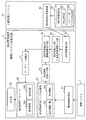
- FIG. 1 shows a configuration example of a configuration management apparatus 2 according to the present embodiment.
- the configuration management device 2 corresponds to an example of an information system management device.
- the configuration management device 2 is connected to the information system 1 that is the actual environment of the business system, and manages the information system 1. More specifically, the configuration management apparatus 2 collects system component information from the information system 1 and analyzes and stores the dependency relationship.
- the information system 1 includes a network, a server device, a terminal device, and the like.
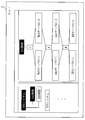
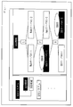
- the configuration management apparatus 2 displays the view 3 illustrated in FIG.
- the information system 1 managed by the configuration management apparatus 2 is composed of, for example, an XXX system, a YYY system, etc., as shown in a view 3 in FIG. 2, and the XXX system is provided with AAA functions and BBB functions.
- FIG. 2 shows a device configuration in the AAA function of the XXX system.
- the Web server # 1-1, Web server # 1-2, App server # 1-1, App server # 1-2, DB server # 1-1, DB Server # 1-2 exists.
- Web server # 1-1, “Web server # 1” in Web server # 1-2, App server # 1-1, “App server # 1” in App server # 1-2, DB server # 1-1, DB “DB server # 1” in server # 1-2 represents a system component.
- Web server # 1-1 and Web server # 1-2 are components used for redundancy in the system component “Web server # 1”.
- the App server # 1-1 and the App server # 1-2 are components used for redundancy in the system component “App server # 1”.
- the DB server # 1-1 and the DB server # 1-2 are components used for redundancy in the system component “DB server # 1”.
- the information system 1 managed by the configuration management apparatus 2 includes a plurality of system components, and each system component is made redundant using two or more components.
- a component is also referred to as a device.
- the configuration management device 2 includes a configuration information collection unit 21, a component element management table storage unit 22, a dependency relationship information input unit 23, a design information storage unit 24, a design information input unit 25, a design information integration unit 26, a database registration unit 27, A configuration management database 28 and a display unit 29 are included.
- the configuration information collection unit 21 communicates with the information system 1 to detect a component that is operating in the information system 1, and also includes dependency relationships between components that are operating in the information system 1, that is, between system components Detect dependencies. Then, the operating device list table 201 and the dependency relationship table 202 showing the dependencies between the components operating in the information system 1 and the system components are generated, and the generated operating device list table 201 and the dependency relationship table 202 are generated. It is stored in the component management table storage unit 22.
- the component management table storage unit 22 stores an operating device list table 201 and a dependency relationship table 202.
- the operating device list table 201 is a table illustrated in FIG. 3, and describes components that are operating in the information system 1.
- the dependency relationship table 202 is a table illustrated in FIG. 4 and describes dependency relationships between system components. Details of the operating device list table 201 and the dependency relationship table 202 will be described later with reference to FIGS.
- the dependency relationship table 202 corresponds to an example of dependency relationship information.
- the dependency relationship information input unit 23 inputs (reads out) the dependency relationship table 202 from the component management table storage unit 22.
- the design information storage unit 24 stores a CFIA analysis table 203 and a host name / IP address correspondence table 204.
- the CFIA analysis table 203 is a table illustrated in FIG. 5 and describes all components included in the information system 1. That is, the CFIA analysis table 203 describes not only main components of each system component but also standby components.
- the CFIA analysis table 203 describes details of redundancy in each system component. For example, “L”, “F”, “M” shown in the CFIA analysis table 203 are redundancy methods, L (Load Balance) is redundancy by load balance, F (Failover) is redundancy by failover, M (Manual) represents redundancy by manual switching (cold standby).
- the host name / IP address correspondence table 204 is a table illustrated in FIG. 6 and describes the communication address (IP address) of each component. Details of the CFIA analysis table 203 and the host name / IP address correspondence table 204 will be described later with reference to FIGS.
- the CFIA analysis table 203 corresponds to an example of redundant detailed information
- the host name / IP address correspondence table 204 corresponds to an example of communication address information.
- the design information input unit 25 inputs (reads out) the CFIA analysis table 203 and the host name / IP address correspondence table 204 from the design information storage unit 24.
- the design information input unit 25 corresponds to an example of a redundant detailed information input unit.
- the design information integration unit 26 uses the dependency relationship table 202, the CFIA analysis table 203, and the host name / IP address correspondence table 204 to describe the redundancy details described in the CFIA analysis table 203 in the dependency relationship table 202.
- the design information integration unit 26 generates a configuration management table 205 illustrated in FIG. Based on the value described in “redundancy” in the configuration management table 205 and the value described in “host name”, the standby component is described in the dependency table 202 for each system component. It will be related to the running component.
- the design information integration unit 26 corresponds to an example of an information association unit.
- the database registration unit 27 registers the configuration management table 205 and the dependency relationship table 202 generated by the design information integration unit 26 in the configuration management database 28.
- the configuration management database 28 stores a configuration management table 205 and a dependency relationship table 202.
- the display unit 29 reads the configuration management table 205 and the dependency relationship table 202 from the configuration management database 28, and generates a view 3 as shown in FIG. 2 based on the configuration management table 205 and the dependency relationship table 202.
- the operating device list table 201 includes items of “system name”, “function”, “device name”, and “host name”.
- the device indicated by “device name” is the name of the component detected by the configuration information collection unit 21 through communication with each device included in the information system 1.
- the “host name” is an ID (Identifier) of the component indicated by the “device name”.
- the dependency relationship table 202 includes items of “system name”, “function”, “host name”, and “dependency destination”.
- the ID shown in “Host name” is the same as that shown in “Host name” of the operating device list table 201 of FIG. That is, it is the ID of the active component detected by the configuration information collection unit 21.
- the ID shown in “Dependency Destination” is the ID of the component on which the component corresponding to the ID of “Host Name” depends on operation. In other words, webabc (Web server # 1-1) and webdef (Web server # 1-2) use the resources of appabc (App server # 1-1) in some form for operation. Further, appabc (App server # 1-1) depends on dbsac (DB server # 1-1).
- the dependency relationship table 202 is also generated by the configuration information collection unit 21.
- the operating device list table 201 is used when the dependency relationship table 202 is generated.
- the operation device list table 201 is not always necessary in the processing of the design information integration unit 26 and the display unit 29. I just need it. Therefore, only the dependency relationship table 202 may be stored in the component management table storage unit 22. Further, the dependency relationship table 202 may be conventional CMDB information.
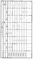
- FIG. 5 shows an example of the CFIA analysis table 203.
- FIG. 5 shows an example of an analysis table of CFIA (Component Failure Impact Analysis) executed at the time of information system design.
- the table of FIG. 5 shows the CFIA analysis result of one business system.
- the host name the effect when the device fails (AAA function, BBB function in FIG. 5), This is a summary of system component failure detection methods.
- the influence on the function when a device fails is represented by a symbol of a redundancy method (for example, L, F, M). As described above, L indicates redundancy by load balancing, F indicates redundancy by failover, and M indicates redundancy by manual switching.
- L indicates redundancy by load balancing
- F indicates redundancy by failover
- M indicates redundancy by manual switching.
- the column of the failure detection method is represented by symbols such as S and P, for example, S (Server survey) represents detection by the server monitoring system, and N (Network survey) represents detection by the network monitoring system.
- FIG. 6 shows an example of the host name / IP address correspondence table 204.
- FIG. 6 is a correspondence table of host names and IP addresses, which is described so that the IP address can be referred to from the host name of the device.
- the CFIA analysis table 203 and the host name / IP address correspondence table 204 are also referred to as “system design information”.
- FIG. 7 shows an example of the configuration management table 205.
- an item “redundancy” is added as compared with the CFIA analysis table 203.
- a standby component of two or more components used for redundancy and the dependency relationship table 202 (FIG. The active component described in 4) is related.
- “appabc” (App server # 1-1) that is operating in the dependency relationship table 202 is associated with “waiting” appdef (App server # 1-2).
- the redundancy method and the active component described in the dependency relationship table 202 are related to each other.
- “appabc” App server # 1-1) operating in the dependency relationship table 202 is associated with the redundancy method “F”.
- the display unit 29 reads the configuration management table 205 and the dependency relationship table 202 from the configuration management database 28, interprets the configuration management table 205 and the dependency relationship table 202, and generates the view 3 illustrated in FIG.
- the view 3 displays the components being operated in each system component and the dependency relationship between the system components, and is operated in each system component based on the configuration management table 205 generated by the design information integration unit 26.
- the details of redundancy in each system component are displayed in association with the display of the components inside. As the details of the redundancy, a redundancy method (L, F, M) in each system component and a standby component in each system component are shown.
- Patent Documents 1 to 3 a view is generated using only the dependency relationship table 202.
- a view illustrated in FIG. 19 is generated. That is, only the dependency between the component in operation in the information system 1 and the component (system component) is shown.
- this embodiment in addition to displaying active components and dependencies between components (system components), there are redundancy methods and standby components for active components. Is displayed.
- the configuration information collection unit 21 communicates with the information system 1, collects device information for each system component such as a network, a server device, and a terminal device, and generates an operation device list table 201.
- the operating device list table 201 is stored in the component management table storage unit 22.
- the dependency relationship information input unit 23 analyzes the dependency relationship between the system components from the communication relationship between the system components for the collected system components, generates the dependency table 202, and generates the generated dependency relationships.
- the table 202 is stored in the component management table storage unit 22.
- the configurations and operations of the configuration information collection unit 21 and the component management table storage unit 22 may be in accordance with any method of Patent Documents 1 to 3 and Non-Patent Document 1.
- the dependency relationship information input unit 23 reads the dependency relationship table 202 from the component management table storage unit 22.
- the design information input unit 25 reads the CFIA analysis table 203 from the design information storage unit 24.
- the design information integration unit 26 generates a configuration management table 205 representing a combination of redundancy in the system components and a redundancy method from the dependency relationship table 202 and the CFIA analysis table 203.
- the database registration unit 27 registers the configuration management table 205 and the dependency relationship table 202 generated by the design information integration unit 26 in the configuration management database 28.
- the display unit 29 generates and displays the view 3 reflecting the contents of the configuration management table 205 and the dependency relationship table 202 of the configuration management database 28.
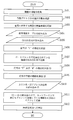
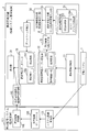
- FIG. 8 is a flowchart illustrating the operation of the configuration management apparatus 2 of FIG.
- Steps S401, S402, and S403 indicate processing of the configuration information collection unit 21 in FIG. That is, the configuration information collection unit 21 collects system component information, checks the communication status of various protocols, and the operation device list table 201 indicating the devices with communication and the dependency indicating the dependency relationship between the devices. A relationship table 202 is generated, and the generated operating device list table 201 and dependency relationship table 202 are stored in the component management table storage unit 22.
- the dependency relationship information input unit 23 reads the dependency relationship table 202 (FIG. 4) from the component management table storage unit 22, and passes the read dependency relationship table 202 to the design information integration unit 26.
- the design information input unit 25 reads the CFIA analysis table 203 (FIG. 5) from the design information storage unit 24 and passes the read CFIA analysis table 203 to the design information integration unit 26.
- Steps S406 to S411 show the processing of the design information integration unit 26 in FIG. Specifically, the design information integration unit 26 extracts a device whose symbol is “L” from the CFIA analysis table 203 in S406. As a result, a combination of devices made redundant by load balancing is found, and the combination is stored (S407). Next, in S408, the design information integration unit 26 extracts devices having the symbols “F” and “M” from the CFIA analysis table 203, and in S409, extracts the devices whose symbols are blank.
- a line with a blank symbol indicates that the function of the system is not affected even if the device fails, it can be determined that this line is an alternative machine (standby machine), and the symbol is “F”.
- the design information input unit 25 reads the host name / IP address correspondence table 204 (FIG. 6) from the design information storage unit 24, and the read host name / IP address correspondence table 204 is used as the design information integration unit 26.
- the design information integration unit 26 exists in the same network segment in the redundant source device (main component) extracted in S408 and the redundant counterpart device (standby component) extracted in S409. Search for the combination you are using and determine the redundant pair. For example, consider a case where a redundant partner device of App server # 1-1 in FIG. 5 is extracted.
- the IP address of the App server # 1-1 is “XXX.YYY.MMM.CCC” as shown in FIG.
- the design information integration unit 26 extracts the IP address “XXX.YYY.MMM.EEE” having a network segment that matches the network segment “XXX.YYY.MMM.” Of the IP address, and the IP address is “host name”. : Appdef "device IP address.
- the design information integration unit 26 can describe in the configuration management table 205 that the redundant partner device of the App server # 1-1 is the App server # 1-2.
- the design information integration unit 26 has a configuration management table 205 (representing the redundancy pair for “F” and “M” determined in S411 and the redundancy pair for “L” extracted in S407. FIG. 7) is generated.
- the database registration unit 27 stores the configuration management table 205 and the dependency relationship table 202 in the configuration management database 28.
- the display unit 29 generates and displays the view 3 shown in FIG. 2 from the configuration management table 205 and the dependency relationship table 202.
- the display unit 29 performs drawing representing the dependency relationship between the operating device and the system component in each system component from the dependency relationship table 202, and also displays the active device in the configuration management table 205.
- the view of FIG. 2 is displayed by rendering the redundant method and the standby device in association with each other.
- the dependency of the system component on the business system displayed as a view is The relationship of redundancy and the type of redundancy (load balance, failover, manual, etc.) can be displayed. For this reason, when a device failure occurs, it can be judged whether there is an impact on the operation of the business system, whether it is switched to a redundant system, whether manual countermeasures are necessary, etc., and it is possible to quickly deal with system failures. it can.
- both the redundancy method and the standby device are displayed, but only the redundancy method is displayed as shown in FIG. 9 (the display of the standby device is omitted).
- the display of the standby device is omitted.
- only standby devices may be displayed (display of the redundancy method is omitted).
- a system configuration information dependency generation system that includes the following means and discriminates the combination and type of system redundant configurations by taking in system design information has been described.
- a configuration information collecting unit that communicates with the information system environment and collects information on system components;
- B A component management table for storing collected system component information;
- C a dependency information input unit for inputting dependency information between system components generated from information collected from the system components;
- D a design information input unit for inputting design information of the information system;
- E A design information integration unit that integrates combinations and types of redundant configurations extracted from the system design information into the dependency relationship of (c);
- F) A database registration unit that stores the information generated in (e) in a database;
- G a configuration management database for storing collected system component information and dependency information between generated system components;
- H A display unit for displaying information of the configuration management database to the user.
- Embodiment 2 FIG. In the first embodiment described above, the details of redundancy are determined for one business system using one CFIA analysis table (FIG. 5). In this embodiment, an example in which redundancy details are determined for a plurality of business systems using two or more CFIA analysis tables is shown.
- the configuration of the configuration management device 2 is as shown in FIG.
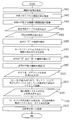
- FIG. 11 is a flowchart showing the processing contents of the configuration management apparatus 2 according to the second embodiment.
- the portions other than S501 and S502 in FIG. 11 are the same as those in FIG.
- the design information input unit 25 reads the CFIA analysis table of another business system in S501.
- the design information integration unit 26 records the business system name and host name of the CFIA analysis table, and S412 The information recorded in the configuration management database 28 is registered.
- the design information integration unit 26 generates a configuration management table 205 for the information system 1 of each business system, compares the generated configuration management tables 205, and includes the same host name in the two configuration management tables 205. If so, the host names included in the two configuration management tables 205 and the business system names of the business systems targeted by the two configuration management tables 205 are recorded in the configuration management database 28 via the database registration unit 27. In addition, the two configuration management tables 205 are stored in the configuration management database 28 via the database registration unit 27.
- the design information integration unit 26 also stores the dependency relationship table 202 in the configuration management database 28 via the database registration unit 27. In this example, two configuration management tables 205 are associated with each other, but the same processing is performed when three or more configuration management tables 205 are associated.
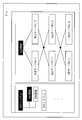
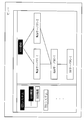
- FIG. 12 shows a view 61 in the case of the second embodiment.
- the view 61 is displayed instead of the view 3 in FIG. 1 of the first embodiment.
- FIG. 12 shows that as a result of performing the processing of FIG. 11 and analyzing a plurality of configuration management tables 205, the DB server # 1 is commonly used for the AAA function of the XXX system and the CCC function of the YYY system. Detected and illustrated.
- the display unit 29 reads the two configuration management tables 205 corresponding to the business system names recorded by the design information integration unit 26 from the configuration management database 28, and also stores the two configuration management tables 205 in the two configuration management tables 205.
- Two corresponding dependency relationship tables 202 are read from the configuration management database 28, and information on the host name recorded by the design information integration unit 26 is read. Then, as in the first embodiment, the display unit 29 uses the configuration management table 205 and the dependency relationship table 202 for each business system, and uses the active device and the standby device for each system component. In addition to showing the redundancy method, a drawing showing the dependency between system components is performed, and the same system component (DB server # 1 in the example of FIG. 12) is duplicated in two business systems. Draw to indicate that.
- the relationship between redundancy of system components of multiple business systems and the type of redundancy can be displayed as a view. It becomes. For this reason, even when system components are shared by multiple business systems, whether a system component failure has an effect on the operation of the business system, whether to switch to a redundant system, whether manual action is required, etc. Judgment can be made and a system failure can be quickly dealt with.
- the design information input unit can input design information of a plurality of business systems, and the design information integration unit analyzes the system component elements commonly used among business systems.
- a possible system configuration information dependency generation system has been described.
- Embodiment 3 In the first and second embodiments described above, the details of redundancy are determined using the CFIA analysis table (FIG. 5) and the host name / IP address correspondence table (FIG. 7). Next, an example using the naming convention of the host name is shown.
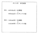
- FIG. 13 shows an example of naming rules for host names.
- the first 3 digits indicate the business type
- the 4th to 8th digits indicate the installation location
- the 9th to 10th digits indicate arbitrary numerical values.
- the partner for redundancy can be determined by performing the matching process for the first three digits. That is, the design information integration unit 26 can determine a device having a common first three digit value as a redundant partner.
- Example 2 indicates the installation location in the first to fifth digits, and the business type in the sixth to eighth digits.
- a host name naming rule table shown in FIG. 14 is prepared in the design information storage unit 24, reflecting such a host name naming rule.
- host name naming rule table for each business system, as a naming rule, it is defined what keyword is assigned to which digit of the host name.
- a host name having “web” or “app” in one to three digits is extracted to determine a redundant partner.
- the host name naming rule table of FIG. 14 is used in place of the host name / IP address correspondence table 204 of the first embodiment or together with the host name / IP address correspondence table 204.
- the design information integration unit 26 selects the device paired with the redundancy source device (main system component) extracted in S408 as the redundant partner extracted in S409.
- the host name naming rule table of FIG. 14 is used. Other operations are the same as those in the first embodiment.
- the system configuration information dependency generation system has been described in which the design information input unit receives a plurality of types of design information, and the design information integration unit improves the discrimination accuracy of the redundant configuration combination. .
- Embodiment 4 FIG. In the first and second embodiments, the details of redundancy are determined using the CFIA analysis table (FIG. 5) and the host name / IP address correspondence table (FIG. 7). An example using a list of software installed in each device is shown.
- a software list table indicating a list of installed software is prepared in the design information storage unit 24 for each device (host name) as shown in FIG.
- “OS” indicates an operating system
- “MW” indicates middleware
- “APP” indicates an application program.
- the item with a check is software installed in the device.
- the software list table of FIG. 15 is used instead of the host name / IP address correspondence table 204 of the first embodiment or together with the host name / IP address correspondence table 204.
- the design information integration unit 26 selects the device paired with the redundancy source device (main system component) extracted in S408 as the redundant partner extracted in S409.
- the software list table of FIG. 15 is used.
- the design information integration unit 26 extracts a device in which the same software group as that installed in the redundancy source device is installed from the software list table, and pairs the extracted device with the redundancy source device. Equipment. Other operations are the same as those in the first embodiment.
- the system configuration information dependency generation system has been described in which the design information input unit receives a plurality of types of design information, and the design information integration unit improves the discrimination accuracy of the redundant configuration combination. .
- Embodiment 5 FIG. In the first to fourth embodiments described above, the system design information is held in the configuration management apparatus 2, but in the fifth embodiment, the system design information is held in an external document management system. An example is shown.
- FIG. 16 is a system configuration diagram according to the present embodiment.
- the document management system 91 collectively manages system design information of a plurality of business systems.
- the document management system 91 includes a design information change detection unit 92.
- the design information change detection unit 92 detects a change in the system design information.
- the configuration management device 2 includes a design information communication unit 93.
- the design information communication unit 93 communicates with the design information change detection unit 92.
- the design information change detection unit 92 detects a change in the system design information
- the design information change detection unit 92 notifies the design information communication unit 93 on the configuration management apparatus 2 and re-imports the system design information (re-execution of S405 to S412 in the flow of FIG. 8). Execute).
- the system dependency, redundancy partner, and redundancy method in the latest system design information can be displayed in the view when a system failure occurs, and the failure response can be accurately performed. It becomes possible to carry out.
- the present embodiment has described the system configuration information dependency generation system that automatically updates the system component dependency by detecting the update of the design information stored in the external document management system. .
- Embodiment 6 In the first to fifth embodiments described above, only the dependency relationship between system components is generated and displayed. However, in the sixth embodiment, an example in which the system fault monitoring information is further linked. Show.
- FIG. 17 is a system configuration diagram according to the present embodiment.
- the fault monitoring system 101 includes a system fault monitoring unit 102 that monitors faults in the information system 1, a fault information database 103 that stores fault information (example of monitoring result information) when a fault is detected as a result of monitoring, and a fault It has a failure information notification unit 104 that notifies information to the outside.
- the failure monitoring system 101 corresponds to an example of a monitoring device.
- the configuration management apparatus 2 is provided with a failure information communication unit 105.
- the failure information communication unit 105 receives failure information from the failure monitoring system 101.
- the failure information communication unit 105 corresponds to an example of a monitoring result information receiving unit.
- the system fault monitoring unit 102 on the fault monitoring system 101 detects a fault by communication by polling to the information system 1 or a notification from a server device or a network device, and details of the fault (host name) detected in the fault information database 103. Log fault messages).
- the failure information notification unit 104 detects the update of the failure information database 103 and notifies the failure information communication unit 105 on the configuration management apparatus 2 of the contents.
- the display unit 29 displays the information on the view 3 in consideration of the failure occurrence status of the system components in addition to the information of the first embodiment. In view 3, in addition to the information of the first embodiment, the device in which the failure has occurred and whether or not the device has been switched due to the occurrence of the failure are displayed. In the example of view 3 in FIG.
- a device that is highlighted (white on a black background) is not currently in service
- a device that is displayed as “ERROR” is a device that has failed
- “STAND- A device displayed as “BY” is an alternative device having a redundant configuration and is a standby device.
- the Web server # 1-1 and Web server # 1-2 are operating correctly due to load balancing, a failure occurs in the App server # 1-1, and the server is switched to the App server # 1-2 correctly. It can be seen that DB server # 1-1 is operating correctly and DB server # 1-2, which is a manual substitute device, is in a standby state.
- the points to be dealt with as a failure response can be clarified, and the failure response can be implemented quickly.
- the failure information of the system component from the failure monitoring system is received and the configuration management database information is displayed, the failure location and the switching presence / absence of the redundant configuration are displayed.
- the dependency generation system was explained.
- FIG. 20 is a diagram illustrating an example of hardware resources of the configuration management apparatus 2 described in the first to sixth embodiments. 20 is merely an example of the hardware configuration of the configuration management device 2, and the hardware configuration of the configuration management device 2 is not limited to the configuration illustrated in FIG. Also good.
- the configuration management apparatus 2 includes a CPU 911 (also referred to as a central processing unit, a central processing unit, a processing unit, a processing unit, a microprocessor, a microcomputer, and a processor) that executes a program.
- the CPU 911 is connected to, for example, a ROM (Read Only Memory) 913, a RAM (Random Access Memory) 914, a communication board 915, a display device 901, a keyboard 902, a mouse 903, and a magnetic disk device 920 via a bus 912. Control hardware devices.
- the CPU 911 may be connected to an FDD 904 (Flexible Disk Drive), a compact disk device 905 (CDD), a printer device 906, and a scanner device 907.
- FDD 904 Flexible Disk Drive
- CDD compact disk device
- printer device 906 printer device 907
- a storage device such as an SSD (Solid State Drive), an optical disk device, or a memory card (registered trademark) read / write device may be used.
- the RAM 914 is an example of a volatile memory.
- the storage media of the ROM 913, the FDD 904, the CDD 905, and the magnetic disk device 920 are an example of a nonvolatile memory. These are examples of the storage device.
- the “component management table storage unit 22”, “design information storage unit 24”, and “configuration management database 28” described in the first to sixth embodiments are realized by the RAM 914, the magnetic disk device 920, and the like.
- a communication board 915, a keyboard 902, a mouse 903, a scanner device 907, and the like are examples of input devices.
- the communication board 915, the display device 901, the printer device 906, and the like are examples of output devices.
- the communication board 915 is connected to the network.
- the communication board 915 is connected to a LAN (local area network), the Internet, a WAN (wide area network), a SAN (storage area network), and the like.
- the magnetic disk device 920 stores an operating system 921 (OS), a window system 922, a program group 923, and a file group 924.
- the programs in the program group 923 are executed by the CPU 911 using the operating system 921 and the window system 922.
- the RAM 914 temporarily stores at least part of the operating system 921 program and application programs to be executed by the CPU 911.
- the RAM 914 stores various data necessary for processing by the CPU 911.
- the ROM 913 stores a BIOS (Basic Input Output System) program
- the magnetic disk device 920 stores a boot program.
- BIOS Basic Input Output System
- the configuration management device 2 is activated, the BIOS program in the ROM 913 and the boot program in the magnetic disk device 920 are executed, and the operating system 921 is activated by the BIOS program and the boot program.
- the program group 923 stores programs that execute the functions described as “-unit” (other than “-storage unit” in the following) in the description of the first to sixth embodiments.
- the program is read and executed by the CPU 911.
- the encryption key / decryption key, random number value, and parameter may be stored as a file in a storage medium such as a disk or memory.
- the “ ⁇ file” and “ ⁇ database” are stored in a storage medium such as a disk or memory.
- Information, data, signal values, variable values, and parameters stored in a storage medium such as a disk or memory are read out to the main memory or cache memory by the CPU 911 via a read / write circuit.
- the read information, data, signal value, variable value, and parameter are used for CPU operations such as extraction, search, reference, comparison, calculation, calculation, processing, editing, output, printing, and display.
- Information, data, signal values, variable values, and parameters are stored in the main memory, registers, cache memory, and buffers during the CPU operations of extraction, search, reference, comparison, calculation, processing, editing, output, printing, and display. It is temporarily stored in a memory or the like.
- the arrows in the flowcharts described in the first to sixth embodiments mainly indicate input / output of data and signals.
- Data and signal values are recorded in a storage medium such as a memory of the RAM 914, a flexible disk of the FDD 904, a compact disk of the CDD 905, a magnetic disk of the magnetic disk device 920, other optical disks, mini disks, and DVDs.
- Data and signals are transmitted online via a bus 912, signal lines, cables, or other transmission media.
- the “information system management method” can be realized by the steps, procedures, and processes shown in the flowcharts described in the first to sixth embodiments.
- the “ ⁇ unit” may be realized by firmware stored in the ROM 913. Alternatively, it may be implemented only by software, or only by hardware such as elements, devices, substrates, and wirings, by a combination of software and hardware, or by a combination of firmware.
- Firmware and software are stored as programs in a storage medium such as a magnetic disk, a flexible disk, an optical disk, a compact disk, a mini disk, and a DVD.
- the program is read by the CPU 911 and executed by the CPU 911. That is, the program causes the computer to function as the “ ⁇ unit” in the first to sixth embodiments. Alternatively, the procedure or method of “—unit” in the first to sixth embodiments is executed by a computer.
- the configuration management device 2 described in the first to sixth embodiments includes a CPU as a processing device, a memory as a storage device, a magnetic disk, a keyboard as an input device, a mouse, a communication board, a display device as an output device, and a communication device.
- a computer including a board or the like.
- the functions indicated as “ ⁇ units” are realized using these processing devices, storage devices, input devices, and output devices.
Priority Applications (6)
| Application Number | Priority Date | Filing Date | Title |
|---|---|---|---|
| SG11201404470VA SG11201404470VA (en) | 2012-02-20 | 2012-02-20 | Information system management apparatus, information system management method, and program |
| JP2012534874A JP5208324B1 (ja) | 2012-02-20 | 2012-02-20 | 情報システム管理装置及び情報システム管理方法及びプログラム |
| US14/374,103 US20150012622A1 (en) | 2012-02-20 | 2012-02-20 | Information system management apparatus, information system management method, and program |
| CN201280070136.9A CN104137086A (zh) | 2012-02-20 | 2012-02-20 | 信息系统管理装置、信息系统管理方法以及程序 |
| PCT/JP2012/053939 WO2013124947A1 (ja) | 2012-02-20 | 2012-02-20 | 情報システム管理装置及び情報システム管理方法及びプログラム |
| EP12868986.6A EP2819020A4 (en) | 2012-02-20 | 2012-02-20 | INFORMATION SYSTEM MANAGEMENT DEVICE AND INFORMATION SYSTEM MANAGEMENT METHOD AND PROGRAM |
Applications Claiming Priority (1)
| Application Number | Priority Date | Filing Date | Title |
|---|---|---|---|
| PCT/JP2012/053939 WO2013124947A1 (ja) | 2012-02-20 | 2012-02-20 | 情報システム管理装置及び情報システム管理方法及びプログラム |
Publications (1)
| Publication Number | Publication Date |
|---|---|
| WO2013124947A1 true WO2013124947A1 (ja) | 2013-08-29 |
Family
ID=48713113
Family Applications (1)
| Application Number | Title | Priority Date | Filing Date |
|---|---|---|---|
| PCT/JP2012/053939 WO2013124947A1 (ja) | 2012-02-20 | 2012-02-20 | 情報システム管理装置及び情報システム管理方法及びプログラム |
Country Status (6)
| Country | Link |
|---|---|
| US (1) | US20150012622A1 (zh) |
| EP (1) | EP2819020A4 (zh) |
| JP (1) | JP5208324B1 (zh) |
| CN (1) | CN104137086A (zh) |
| SG (1) | SG11201404470VA (zh) |
| WO (1) | WO2013124947A1 (zh) |
Cited By (1)
| Publication number | Priority date | Publication date | Assignee | Title |
|---|---|---|---|---|
| JP2016031657A (ja) * | 2014-07-29 | 2016-03-07 | 三菱重工業株式会社 | システム管理装置およびシステム |
Families Citing this family (5)
| Publication number | Priority date | Publication date | Assignee | Title |
|---|---|---|---|---|
| JP6063576B2 (ja) * | 2013-09-12 | 2017-01-18 | 株式会社日立製作所 | サーバシステム、計算機システム、サーバシステムの管理方法、及びコンピュータ読み取り可能な記憶媒体 |
| JP2016177324A (ja) | 2015-03-18 | 2016-10-06 | 株式会社リコー | 情報処理装置、情報処理システム、情報処理方法、及びプログラム |
| US11574372B2 (en) * | 2017-02-08 | 2023-02-07 | Upstream Data Inc. | Blockchain mine at oil or gas facility |
| JP6788555B2 (ja) * | 2017-08-07 | 2020-11-25 | 株式会社東芝 | 情報処理システム、情報処理装置、及び情報処理方法 |
| US11907029B2 (en) | 2019-05-15 | 2024-02-20 | Upstream Data Inc. | Portable blockchain mining system and methods of use |
Citations (6)
| Publication number | Priority date | Publication date | Assignee | Title |
|---|---|---|---|---|
| JP2000013372A (ja) * | 1998-06-19 | 2000-01-14 | Nec Corp | ネットワーク管理装置 |
| JP2000286873A (ja) * | 1999-03-30 | 2000-10-13 | Seiko Epson Corp | ネットワーク管理システム |
| JP2004103015A (ja) | 2002-09-11 | 2004-04-02 | Internatl Business Mach Corp <Ibm> | 分散型システムにおける依存性管理の方法および装置 |
| JP2005275533A (ja) | 2004-03-23 | 2005-10-06 | Nec Corp | コンピュータネットワーク管理システム、コンピュータネットワーク管理方法およびプログラム |
| JP2006178834A (ja) | 2004-12-24 | 2006-07-06 | Mitsubishi Electric Corp | 依存関係情報収集システム及び依存関係情報収集方法 |
| JP2011243001A (ja) * | 2010-05-18 | 2011-12-01 | Nec Corp | Itシステムの構成監視方法および構成監視装置と構成監視プログラム |
Family Cites Families (14)
| Publication number | Priority date | Publication date | Assignee | Title |
|---|---|---|---|---|
| EP0996152A1 (en) * | 1998-10-23 | 2000-04-26 | STMicroelectronics S.r.l. | Process for manufacturing electronic devices comprising non-salicidated nonvolatile memory cells, non-salicidated HV transistors, and salicidated-junction LV transistors |
| US7278103B1 (en) * | 2000-06-28 | 2007-10-02 | Microsoft Corporation | User interface to display and manage an entity and associated resources |
| DE60045348D1 (de) * | 2000-09-28 | 2011-01-20 | Ntt Comware Corp | Computersystem, Steuerverfahren für ein Computersystem und Aufzeichnungsmedium |
| US7418484B2 (en) * | 2001-11-30 | 2008-08-26 | Oracle International Corporation | System and method for actively managing an enterprise of configurable components |
| US6996502B2 (en) * | 2004-01-20 | 2006-02-07 | International Business Machines Corporation | Remote enterprise management of high availability systems |
| DE102005004151A1 (de) * | 2005-01-28 | 2006-08-10 | Siemens Ag | Verfahren und Vorrichtung zur Zuordnung von Paketadressen einer Mehrzahl von Einrichtung |
| US10896393B2 (en) * | 2006-12-19 | 2021-01-19 | International Business Machines Corporation | Autonomic control of calibration for pointing device |
| CN100442233C (zh) * | 2007-01-31 | 2008-12-10 | 华为技术有限公司 | 实现应用系统动态升级的方法及系统 |
| US8719624B2 (en) * | 2007-12-26 | 2014-05-06 | Nec Corporation | Redundant configuration management system and method |
| US10079723B2 (en) * | 2008-12-31 | 2018-09-18 | International Business Machines Corporation | Dynamic high availability policy creation based upon entries in a configuration management database (CMDB) and a best practices template |
| US8661286B2 (en) * | 2010-05-21 | 2014-02-25 | Unisys Corporation | QProcessor architecture in a cluster configuration |
| JP5549374B2 (ja) * | 2010-05-24 | 2014-07-16 | 富士通株式会社 | 負荷分散装置及び負荷分散制御方法 |
| JP5527027B2 (ja) * | 2010-06-04 | 2014-06-18 | 富士通株式会社 | スキーマ定義生成装置、スキーマ定義生成方法およびスキーマ定義生成プログラム |
| US8738961B2 (en) * | 2010-08-17 | 2014-05-27 | International Business Machines Corporation | High-availability computer cluster with failover support based on a resource map |
-
2012
- 2012-02-20 EP EP12868986.6A patent/EP2819020A4/en not_active Withdrawn
- 2012-02-20 WO PCT/JP2012/053939 patent/WO2013124947A1/ja active Application Filing
- 2012-02-20 CN CN201280070136.9A patent/CN104137086A/zh active Pending
- 2012-02-20 JP JP2012534874A patent/JP5208324B1/ja not_active Expired - Fee Related
- 2012-02-20 SG SG11201404470VA patent/SG11201404470VA/en unknown
- 2012-02-20 US US14/374,103 patent/US20150012622A1/en not_active Abandoned
Patent Citations (6)
| Publication number | Priority date | Publication date | Assignee | Title |
|---|---|---|---|---|
| JP2000013372A (ja) * | 1998-06-19 | 2000-01-14 | Nec Corp | ネットワーク管理装置 |
| JP2000286873A (ja) * | 1999-03-30 | 2000-10-13 | Seiko Epson Corp | ネットワーク管理システム |
| JP2004103015A (ja) | 2002-09-11 | 2004-04-02 | Internatl Business Mach Corp <Ibm> | 分散型システムにおける依存性管理の方法および装置 |
| JP2005275533A (ja) | 2004-03-23 | 2005-10-06 | Nec Corp | コンピュータネットワーク管理システム、コンピュータネットワーク管理方法およびプログラム |
| JP2006178834A (ja) | 2004-12-24 | 2006-07-06 | Mitsubishi Electric Corp | 依存関係情報収集システム及び依存関係情報収集方法 |
| JP2011243001A (ja) * | 2010-05-18 | 2011-12-01 | Nec Corp | Itシステムの構成監視方法および構成監視装置と構成監視プログラム |
Non-Patent Citations (2)
| Title |
|---|
| BART JACOB ET AL.: "IBM (Registered Trademark) Redbook", February 2002, article "IBM (Registered Trademark) Tivoli Application Dependency Discovery Manager Capabilities and Best Practices", pages: 8 - 9 |
| See also references of EP2819020A4 |
Cited By (1)
| Publication number | Priority date | Publication date | Assignee | Title |
|---|---|---|---|---|
| JP2016031657A (ja) * | 2014-07-29 | 2016-03-07 | 三菱重工業株式会社 | システム管理装置およびシステム |
Also Published As
| Publication number | Publication date |
|---|---|
| US20150012622A1 (en) | 2015-01-08 |
| CN104137086A (zh) | 2014-11-05 |
| JP5208324B1 (ja) | 2013-06-12 |
| EP2819020A4 (en) | 2015-06-24 |
| JPWO2013124947A1 (ja) | 2015-05-21 |
| SG11201404470VA (en) | 2014-11-27 |
| EP2819020A1 (en) | 2014-12-31 |
Similar Documents
| Publication | Publication Date | Title |
|---|---|---|
| WO2009110111A1 (ja) | サーバ装置及びサーバ装置の異常検知方法及びサーバ装置の異常検知プログラム | |
| JP5325981B2 (ja) | 管理サーバ及び管理システム | |
| JP5208324B1 (ja) | 情報システム管理装置及び情報システム管理方法及びプログラム | |
| US10462027B2 (en) | Cloud network stability | |
| JP4130615B2 (ja) | ストレージ装置を有するネットワークにおける障害情報管理方法及び管理サーバ | |
| US20140207929A1 (en) | Management apparatus and management method | |
| US11789760B2 (en) | Alerting, diagnosing, and transmitting computer issues to a technical resource in response to an indication of occurrence by an end user | |
| US10185614B2 (en) | Generic alarm correlation by means of normalized alarm codes | |
| JP2014102661A (ja) | 適用判定プログラム、障害検出装置および適用判定方法 | |
| US10747561B2 (en) | Log management device and log management method | |
| US9021078B2 (en) | Management method and management system | |
| JP5936798B2 (ja) | ログ分析装置、不正アクセス監査システム、ログ分析プログラム及びログ分析方法 | |
| JP2011113122A (ja) | 障害影響分析装置及び業務システム及び障害影響分析方法 | |
| US8473788B2 (en) | Monitoring program, monitoring apparatus, and monitoring method | |
| JP2017211806A (ja) | 通信の監視方法、セキュリティ管理システム及びプログラム | |
| JP2011014094A (ja) | ソフトウェア更新情報管理装置及びプログラム | |
| EP4088437A1 (en) | Correlation-based network security | |
| JP4510040B2 (ja) | インストール支援装置及びインストール支援プログラム及びインストール支援方法 | |
| JP7167749B2 (ja) | 情報処理装置、情報処理システム、及び情報処理プログラム | |
| US20220391277A1 (en) | Computing cluster health reporting engine | |
| JP4575462B2 (ja) | ストレージ装置を有するネットワークにおける障害情報管理方法及び管理サーバ | |
| JP2012168687A (ja) | 情報処理装置及び情報処理方法及びプログラム | |
| JP2020107155A (ja) | 遠隔管理システムおよび情報分析プログラム | |
| JP2008276804A (ja) | ストレージ装置を有するネットワークにおける、ボリューム及び障害管理方法 | |
| JP2011198254A (ja) | 手順出力装置及び手順出力装置の手順出力方法及び手順出力装置の手順出力プログラム |
Legal Events
| Date | Code | Title | Description |
|---|---|---|---|
| ENP | Entry into the national phase |
Ref document number: 2012534874 Country of ref document: JP Kind code of ref document: A |
|
| 121 | Ep: the epo has been informed by wipo that ep was designated in this application |
Ref document number: 12868986 Country of ref document: EP Kind code of ref document: A1 |
|
| WWE | Wipo information: entry into national phase |
Ref document number: 2012868986 Country of ref document: EP |
|
| WWE | Wipo information: entry into national phase |
Ref document number: 14374103 Country of ref document: US |
|
| NENP | Non-entry into the national phase |
Ref country code: DE |