WO2013124947A1 - 情報システム管理装置及び情報システム管理方法及びプログラム - Google Patents
情報システム管理装置及び情報システム管理方法及びプログラム Download PDFInfo
- Publication number
- WO2013124947A1 WO2013124947A1 PCT/JP2012/053939 JP2012053939W WO2013124947A1 WO 2013124947 A1 WO2013124947 A1 WO 2013124947A1 JP 2012053939 W JP2012053939 W JP 2012053939W WO 2013124947 A1 WO2013124947 A1 WO 2013124947A1
- Authority
- WO
- WIPO (PCT)
- Prior art keywords
- information
- component
- system component
- redundancy
- components
- Prior art date
Links
Images


Classifications
-
- H—ELECTRICITY
- H04—ELECTRIC COMMUNICATION TECHNIQUE
- H04L—TRANSMISSION OF DIGITAL INFORMATION, e.g. TELEGRAPHIC COMMUNICATION
- H04L41/00—Arrangements for maintenance, administration or management of data switching networks, e.g. of packet switching networks
- H04L41/08—Configuration management of networks or network elements
- H04L41/085—Retrieval of network configuration; Tracking network configuration history
-
- H—ELECTRICITY
- H04—ELECTRIC COMMUNICATION TECHNIQUE
- H04L—TRANSMISSION OF DIGITAL INFORMATION, e.g. TELEGRAPHIC COMMUNICATION
- H04L41/00—Arrangements for maintenance, administration or management of data switching networks, e.g. of packet switching networks
- H04L41/22—Arrangements for maintenance, administration or management of data switching networks, e.g. of packet switching networks comprising specially adapted graphical user interfaces [GUI]
-
- G—PHYSICS
- G06—COMPUTING; CALCULATING OR COUNTING
- G06F—ELECTRIC DIGITAL DATA PROCESSING
- G06F9/00—Arrangements for program control, e.g. control units
- G06F9/06—Arrangements for program control, e.g. control units using stored programs, i.e. using an internal store of processing equipment to receive or retain programs
- G06F9/44—Arrangements for executing specific programs
- G06F9/445—Program loading or initiating
- G06F9/44505—Configuring for program initiating, e.g. using registry, configuration files
-
- G—PHYSICS
- G06—COMPUTING; CALCULATING OR COUNTING
- G06Q—INFORMATION AND COMMUNICATION TECHNOLOGY [ICT] SPECIALLY ADAPTED FOR ADMINISTRATIVE, COMMERCIAL, FINANCIAL, MANAGERIAL OR SUPERVISORY PURPOSES; SYSTEMS OR METHODS SPECIALLY ADAPTED FOR ADMINISTRATIVE, COMMERCIAL, FINANCIAL, MANAGERIAL OR SUPERVISORY PURPOSES, NOT OTHERWISE PROVIDED FOR
- G06Q10/00—Administration; Management
- G06Q10/10—Office automation; Time management
-
- H—ELECTRICITY
- H04—ELECTRIC COMMUNICATION TECHNIQUE
- H04L—TRANSMISSION OF DIGITAL INFORMATION, e.g. TELEGRAPHIC COMMUNICATION
- H04L41/00—Arrangements for maintenance, administration or management of data switching networks, e.g. of packet switching networks
- H04L41/06—Management of faults, events, alarms or notifications
- H04L41/0631—Management of faults, events, alarms or notifications using root cause analysis; using analysis of correlation between notifications, alarms or events based on decision criteria, e.g. hierarchy, tree or time analysis
- H04L41/065—Management of faults, events, alarms or notifications using root cause analysis; using analysis of correlation between notifications, alarms or events based on decision criteria, e.g. hierarchy, tree or time analysis involving logical or physical relationship, e.g. grouping and hierarchies
-
- H—ELECTRICITY
- H04—ELECTRIC COMMUNICATION TECHNIQUE
- H04L—TRANSMISSION OF DIGITAL INFORMATION, e.g. TELEGRAPHIC COMMUNICATION
- H04L41/00—Arrangements for maintenance, administration or management of data switching networks, e.g. of packet switching networks
- H04L41/06—Management of faults, events, alarms or notifications
- H04L41/0654—Management of faults, events, alarms or notifications using network fault recovery
- H04L41/0668—Management of faults, events, alarms or notifications using network fault recovery by dynamic selection of recovery network elements, e.g. replacement by the most appropriate element after failure
-
- H—ELECTRICITY
- H04—ELECTRIC COMMUNICATION TECHNIQUE
- H04L—TRANSMISSION OF DIGITAL INFORMATION, e.g. TELEGRAPHIC COMMUNICATION
- H04L41/00—Arrangements for maintenance, administration or management of data switching networks, e.g. of packet switching networks
- H04L41/08—Configuration management of networks or network elements
- H04L41/085—Retrieval of network configuration; Tracking network configuration history
- H04L41/0853—Retrieval of network configuration; Tracking network configuration history by actively collecting configuration information or by backing up configuration information
- H04L41/0856—Retrieval of network configuration; Tracking network configuration history by actively collecting configuration information or by backing up configuration information by backing up or archiving configuration information
-
- H—ELECTRICITY
- H04—ELECTRIC COMMUNICATION TECHNIQUE
- H04L—TRANSMISSION OF DIGITAL INFORMATION, e.g. TELEGRAPHIC COMMUNICATION
- H04L41/00—Arrangements for maintenance, administration or management of data switching networks, e.g. of packet switching networks
- H04L41/08—Configuration management of networks or network elements
- H04L41/0893—Assignment of logical groups to network elements
Definitions
- the present invention relates to a technique for managing a redundant information system.
- a configuration management apparatus using a conventional CMDB (Configuration Management Database) or the like communicates with devices (servers, terminals, network devices, software, storage, etc.) constituting an information system to be managed to obtain information. Collecting, storing the dependency relationship between devices in a database or the like, and automatically collecting and storing the dependency relationship between devices (for example, Patent Document 1, Patent Document 2, Non-Patent Document 1). In addition, a method has been proposed in which the configuration management device automatically monitors the connection from the client (terminal) to the software service on the server and automatically collects and stores the dependency between the devices of the information system (for example, patents). Reference 3).
- CMDB Configuration Management Database
- This invention mainly aims to solve these problems, and it is a main object to realize a configuration capable of displaying details of redundancy in an information system.
- An information system management apparatus that manages an information system that includes a plurality of system components and in which redundancy using two or more components is implemented in each system component, Dependency information input that inputs dependency information that describes the components that are running on each system component and the dependencies between the system components, generated by communication with the components that are running on each system component And A redundant detailed information input unit for inputting redundant detailed information describing details of redundancy in each system component; An information associating unit for associating the details of redundancy described in the redundancy detailed information with respect to components operating in each system component described in the dependency relationship information; Displays the components operating in each system component and the dependency relationship between the system components described in the dependency information, and is operating in each system component based on the relationship by the information correlating unit. And a display unit for displaying details of redundancy in each system component in association with the display of the component.
- FIG. 1 is a diagram illustrating a configuration example of a configuration management apparatus according to Embodiment 1.
- FIG. FIG. 6 is a diagram illustrating an example of a view according to the first embodiment.
- FIG. 4 shows an example of an operating device list table according to the first embodiment.
- FIG. 4 is a diagram illustrating an example of a dependency relationship table according to the first embodiment.
- FIG. 3 shows an example of a CFIA analysis table according to the first embodiment.
- FIG. 3 shows an example of a host name / IP address correspondence table according to the first embodiment.
- FIG. 4 is a diagram illustrating an example of a configuration management table according to the first embodiment.
- FIG. 3 is a flowchart showing an operation example of the configuration management apparatus according to the first embodiment.
- FIG. 6 is a diagram illustrating an example of a view according to the first embodiment.
- FIG. 6 is a diagram illustrating an example of a view according to the first embodiment.
- FIG. 9 is a flowchart showing an operation example of the configuration management apparatus according to the second embodiment.
- FIG. 10 is a diagram illustrating an example of a view according to the second embodiment.
- FIG. 11 is a diagram illustrating an example of host name command rules according to the third embodiment.
- FIG. 10 is a diagram showing an example of a host name naming rule table according to the third embodiment.
- FIG. 10 is a diagram showing an example of a software list table according to the fourth embodiment.
- FIG. 10 is a diagram illustrating a configuration example of a configuration management apparatus according to a fifth embodiment.
- FIG. 10 is a diagram illustrating a configuration example of a configuration management apparatus according to a sixth embodiment.
- FIG. 20 shows an example of a view according to Embodiment 6; The figure which shows the example of the conventional view.
- FIG. 7 is a diagram illustrating a hardware configuration example of a configuration management apparatus according to the first to sixth embodiments.
- Embodiment 1 FIG.
- the configuration management apparatus automatically determines the combination and type of redundancy in the system component with respect to the generation of the dependency relationship of the system component, and determines the determined combination and type of redundancy. Is intended to be displayed to the user.
- Redundant configurations include methods such as load balance, failover cluster, and cold standby.
- Load balance is a service in which two or more devices are always providing services, and even if one device breaks down, other devices can perform alternative operations.
- the failover cluster a standby system device that can be automatically switched to the production system device is prepared, and when the production system fails, the standby system device is automatically switched to perform a substitute operation.
- cold standby an alternative device that normally stops operating is prepared for the production system device, and when the production system fails, the alternative device is manually activated to perform an alternative operation.
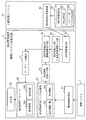
- FIG. 1 shows a configuration example of a configuration management apparatus 2 according to the present embodiment.
- the configuration management device 2 corresponds to an example of an information system management device.
- the configuration management device 2 is connected to the information system 1 that is the actual environment of the business system, and manages the information system 1. More specifically, the configuration management apparatus 2 collects system component information from the information system 1 and analyzes and stores the dependency relationship.
- the information system 1 includes a network, a server device, a terminal device, and the like.
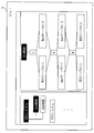
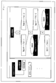
- the configuration management apparatus 2 displays the view 3 illustrated in FIG.
- the information system 1 managed by the configuration management apparatus 2 is composed of, for example, an XXX system, a YYY system, etc., as shown in a view 3 in FIG. 2, and the XXX system is provided with AAA functions and BBB functions.
- FIG. 2 shows a device configuration in the AAA function of the XXX system.
- the Web server # 1-1, Web server # 1-2, App server # 1-1, App server # 1-2, DB server # 1-1, DB Server # 1-2 exists.
- Web server # 1-1, “Web server # 1” in Web server # 1-2, App server # 1-1, “App server # 1” in App server # 1-2, DB server # 1-1, DB “DB server # 1” in server # 1-2 represents a system component.
- Web server # 1-1 and Web server # 1-2 are components used for redundancy in the system component “Web server # 1”.
- the App server # 1-1 and the App server # 1-2 are components used for redundancy in the system component “App server # 1”.
- the DB server # 1-1 and the DB server # 1-2 are components used for redundancy in the system component “DB server # 1”.
- the information system 1 managed by the configuration management apparatus 2 includes a plurality of system components, and each system component is made redundant using two or more components.
- a component is also referred to as a device.
- the configuration management device 2 includes a configuration information collection unit 21, a component element management table storage unit 22, a dependency relationship information input unit 23, a design information storage unit 24, a design information input unit 25, a design information integration unit 26, a database registration unit 27, A configuration management database 28 and a display unit 29 are included.
- the configuration information collection unit 21 communicates with the information system 1 to detect a component that is operating in the information system 1, and also includes dependency relationships between components that are operating in the information system 1, that is, between system components Detect dependencies. Then, the operating device list table 201 and the dependency relationship table 202 showing the dependencies between the components operating in the information system 1 and the system components are generated, and the generated operating device list table 201 and the dependency relationship table 202 are generated. It is stored in the component management table storage unit 22.
- the component management table storage unit 22 stores an operating device list table 201 and a dependency relationship table 202.
- the operating device list table 201 is a table illustrated in FIG. 3, and describes components that are operating in the information system 1.
- the dependency relationship table 202 is a table illustrated in FIG. 4 and describes dependency relationships between system components. Details of the operating device list table 201 and the dependency relationship table 202 will be described later with reference to FIGS.
- the dependency relationship table 202 corresponds to an example of dependency relationship information.
- the dependency relationship information input unit 23 inputs (reads out) the dependency relationship table 202 from the component management table storage unit 22.
- the design information storage unit 24 stores a CFIA analysis table 203 and a host name / IP address correspondence table 204.
- the CFIA analysis table 203 is a table illustrated in FIG. 5 and describes all components included in the information system 1. That is, the CFIA analysis table 203 describes not only main components of each system component but also standby components.
- the CFIA analysis table 203 describes details of redundancy in each system component. For example, “L”, “F”, “M” shown in the CFIA analysis table 203 are redundancy methods, L (Load Balance) is redundancy by load balance, F (Failover) is redundancy by failover, M (Manual) represents redundancy by manual switching (cold standby).
- the host name / IP address correspondence table 204 is a table illustrated in FIG. 6 and describes the communication address (IP address) of each component. Details of the CFIA analysis table 203 and the host name / IP address correspondence table 204 will be described later with reference to FIGS.
- the CFIA analysis table 203 corresponds to an example of redundant detailed information
- the host name / IP address correspondence table 204 corresponds to an example of communication address information.
- the design information input unit 25 inputs (reads out) the CFIA analysis table 203 and the host name / IP address correspondence table 204 from the design information storage unit 24.
- the design information input unit 25 corresponds to an example of a redundant detailed information input unit.
- the design information integration unit 26 uses the dependency relationship table 202, the CFIA analysis table 203, and the host name / IP address correspondence table 204 to describe the redundancy details described in the CFIA analysis table 203 in the dependency relationship table 202.
- the design information integration unit 26 generates a configuration management table 205 illustrated in FIG. Based on the value described in “redundancy” in the configuration management table 205 and the value described in “host name”, the standby component is described in the dependency table 202 for each system component. It will be related to the running component.
- the design information integration unit 26 corresponds to an example of an information association unit.
- the database registration unit 27 registers the configuration management table 205 and the dependency relationship table 202 generated by the design information integration unit 26 in the configuration management database 28.
- the configuration management database 28 stores a configuration management table 205 and a dependency relationship table 202.
- the display unit 29 reads the configuration management table 205 and the dependency relationship table 202 from the configuration management database 28, and generates a view 3 as shown in FIG. 2 based on the configuration management table 205 and the dependency relationship table 202.
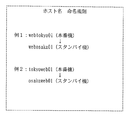
- the operating device list table 201 includes items of “system name”, “function”, “device name”, and “host name”.
- the device indicated by “device name” is the name of the component detected by the configuration information collection unit 21 through communication with each device included in the information system 1.
- the “host name” is an ID (Identifier) of the component indicated by the “device name”.
- the dependency relationship table 202 includes items of “system name”, “function”, “host name”, and “dependency destination”.
- the ID shown in “Host name” is the same as that shown in “Host name” of the operating device list table 201 of FIG. That is, it is the ID of the active component detected by the configuration information collection unit 21.
- the ID shown in “Dependency Destination” is the ID of the component on which the component corresponding to the ID of “Host Name” depends on operation. In other words, webabc (Web server # 1-1) and webdef (Web server # 1-2) use the resources of appabc (App server # 1-1) in some form for operation. Further, appabc (App server # 1-1) depends on dbsac (DB server # 1-1).
- the dependency relationship table 202 is also generated by the configuration information collection unit 21.
- the operating device list table 201 is used when the dependency relationship table 202 is generated.
- the operation device list table 201 is not always necessary in the processing of the design information integration unit 26 and the display unit 29. I just need it. Therefore, only the dependency relationship table 202 may be stored in the component management table storage unit 22. Further, the dependency relationship table 202 may be conventional CMDB information.
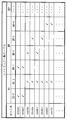
- FIG. 5 shows an example of the CFIA analysis table 203.
- FIG. 5 shows an example of an analysis table of CFIA (Component Failure Impact Analysis) executed at the time of information system design.
- the table of FIG. 5 shows the CFIA analysis result of one business system.
- the host name the effect when the device fails (AAA function, BBB function in FIG. 5), This is a summary of system component failure detection methods.
- the influence on the function when a device fails is represented by a symbol of a redundancy method (for example, L, F, M). As described above, L indicates redundancy by load balancing, F indicates redundancy by failover, and M indicates redundancy by manual switching.
- L indicates redundancy by load balancing
- F indicates redundancy by failover
- M indicates redundancy by manual switching.
- the column of the failure detection method is represented by symbols such as S and P, for example, S (Server survey) represents detection by the server monitoring system, and N (Network survey) represents detection by the network monitoring system.
- FIG. 6 shows an example of the host name / IP address correspondence table 204.
- FIG. 6 is a correspondence table of host names and IP addresses, which is described so that the IP address can be referred to from the host name of the device.
- the CFIA analysis table 203 and the host name / IP address correspondence table 204 are also referred to as “system design information”.
- FIG. 7 shows an example of the configuration management table 205.
- an item “redundancy” is added as compared with the CFIA analysis table 203.
- a standby component of two or more components used for redundancy and the dependency relationship table 202 (FIG. The active component described in 4) is related.
- “appabc” (App server # 1-1) that is operating in the dependency relationship table 202 is associated with “waiting” appdef (App server # 1-2).
- the redundancy method and the active component described in the dependency relationship table 202 are related to each other.
- “appabc” App server # 1-1) operating in the dependency relationship table 202 is associated with the redundancy method “F”.
- the display unit 29 reads the configuration management table 205 and the dependency relationship table 202 from the configuration management database 28, interprets the configuration management table 205 and the dependency relationship table 202, and generates the view 3 illustrated in FIG.
- the view 3 displays the components being operated in each system component and the dependency relationship between the system components, and is operated in each system component based on the configuration management table 205 generated by the design information integration unit 26.
- the details of redundancy in each system component are displayed in association with the display of the components inside. As the details of the redundancy, a redundancy method (L, F, M) in each system component and a standby component in each system component are shown.
- Patent Documents 1 to 3 a view is generated using only the dependency relationship table 202.
- a view illustrated in FIG. 19 is generated. That is, only the dependency between the component in operation in the information system 1 and the component (system component) is shown.
- this embodiment in addition to displaying active components and dependencies between components (system components), there are redundancy methods and standby components for active components. Is displayed.
- the configuration information collection unit 21 communicates with the information system 1, collects device information for each system component such as a network, a server device, and a terminal device, and generates an operation device list table 201.
- the operating device list table 201 is stored in the component management table storage unit 22.
- the dependency relationship information input unit 23 analyzes the dependency relationship between the system components from the communication relationship between the system components for the collected system components, generates the dependency table 202, and generates the generated dependency relationships.
- the table 202 is stored in the component management table storage unit 22.
- the configurations and operations of the configuration information collection unit 21 and the component management table storage unit 22 may be in accordance with any method of Patent Documents 1 to 3 and Non-Patent Document 1.
- the dependency relationship information input unit 23 reads the dependency relationship table 202 from the component management table storage unit 22.
- the design information input unit 25 reads the CFIA analysis table 203 from the design information storage unit 24.
- the design information integration unit 26 generates a configuration management table 205 representing a combination of redundancy in the system components and a redundancy method from the dependency relationship table 202 and the CFIA analysis table 203.
- the database registration unit 27 registers the configuration management table 205 and the dependency relationship table 202 generated by the design information integration unit 26 in the configuration management database 28.
- the display unit 29 generates and displays the view 3 reflecting the contents of the configuration management table 205 and the dependency relationship table 202 of the configuration management database 28.
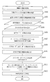
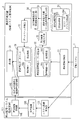
- FIG. 8 is a flowchart illustrating the operation of the configuration management apparatus 2 of FIG.
- Steps S401, S402, and S403 indicate processing of the configuration information collection unit 21 in FIG. That is, the configuration information collection unit 21 collects system component information, checks the communication status of various protocols, and the operation device list table 201 indicating the devices with communication and the dependency indicating the dependency relationship between the devices. A relationship table 202 is generated, and the generated operating device list table 201 and dependency relationship table 202 are stored in the component management table storage unit 22.
- the dependency relationship information input unit 23 reads the dependency relationship table 202 (FIG. 4) from the component management table storage unit 22, and passes the read dependency relationship table 202 to the design information integration unit 26.
- the design information input unit 25 reads the CFIA analysis table 203 (FIG. 5) from the design information storage unit 24 and passes the read CFIA analysis table 203 to the design information integration unit 26.
- Steps S406 to S411 show the processing of the design information integration unit 26 in FIG. Specifically, the design information integration unit 26 extracts a device whose symbol is “L” from the CFIA analysis table 203 in S406. As a result, a combination of devices made redundant by load balancing is found, and the combination is stored (S407). Next, in S408, the design information integration unit 26 extracts devices having the symbols “F” and “M” from the CFIA analysis table 203, and in S409, extracts the devices whose symbols are blank.
- a line with a blank symbol indicates that the function of the system is not affected even if the device fails, it can be determined that this line is an alternative machine (standby machine), and the symbol is “F”.
- the design information input unit 25 reads the host name / IP address correspondence table 204 (FIG. 6) from the design information storage unit 24, and the read host name / IP address correspondence table 204 is used as the design information integration unit 26.
- the design information integration unit 26 exists in the same network segment in the redundant source device (main component) extracted in S408 and the redundant counterpart device (standby component) extracted in S409. Search for the combination you are using and determine the redundant pair. For example, consider a case where a redundant partner device of App server # 1-1 in FIG. 5 is extracted.
- the IP address of the App server # 1-1 is “XXX.YYY.MMM.CCC” as shown in FIG.
- the design information integration unit 26 extracts the IP address “XXX.YYY.MMM.EEE” having a network segment that matches the network segment “XXX.YYY.MMM.” Of the IP address, and the IP address is “host name”. : Appdef "device IP address.
- the design information integration unit 26 can describe in the configuration management table 205 that the redundant partner device of the App server # 1-1 is the App server # 1-2.
- the design information integration unit 26 has a configuration management table 205 (representing the redundancy pair for “F” and “M” determined in S411 and the redundancy pair for “L” extracted in S407. FIG. 7) is generated.
- the database registration unit 27 stores the configuration management table 205 and the dependency relationship table 202 in the configuration management database 28.
- the display unit 29 generates and displays the view 3 shown in FIG. 2 from the configuration management table 205 and the dependency relationship table 202.
- the display unit 29 performs drawing representing the dependency relationship between the operating device and the system component in each system component from the dependency relationship table 202, and also displays the active device in the configuration management table 205.
- the view of FIG. 2 is displayed by rendering the redundant method and the standby device in association with each other.
- the dependency of the system component on the business system displayed as a view is The relationship of redundancy and the type of redundancy (load balance, failover, manual, etc.) can be displayed. For this reason, when a device failure occurs, it can be judged whether there is an impact on the operation of the business system, whether it is switched to a redundant system, whether manual countermeasures are necessary, etc., and it is possible to quickly deal with system failures. it can.
- both the redundancy method and the standby device are displayed, but only the redundancy method is displayed as shown in FIG. 9 (the display of the standby device is omitted).
- the display of the standby device is omitted.
- only standby devices may be displayed (display of the redundancy method is omitted).
- a system configuration information dependency generation system that includes the following means and discriminates the combination and type of system redundant configurations by taking in system design information has been described.
- a configuration information collecting unit that communicates with the information system environment and collects information on system components;
- B A component management table for storing collected system component information;
- C a dependency information input unit for inputting dependency information between system components generated from information collected from the system components;
- D a design information input unit for inputting design information of the information system;
- E A design information integration unit that integrates combinations and types of redundant configurations extracted from the system design information into the dependency relationship of (c);
- F) A database registration unit that stores the information generated in (e) in a database;
- G a configuration management database for storing collected system component information and dependency information between generated system components;
- H A display unit for displaying information of the configuration management database to the user.
- Embodiment 2 FIG. In the first embodiment described above, the details of redundancy are determined for one business system using one CFIA analysis table (FIG. 5). In this embodiment, an example in which redundancy details are determined for a plurality of business systems using two or more CFIA analysis tables is shown.
- the configuration of the configuration management device 2 is as shown in FIG.
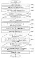
- FIG. 11 is a flowchart showing the processing contents of the configuration management apparatus 2 according to the second embodiment.
- the portions other than S501 and S502 in FIG. 11 are the same as those in FIG.
- the design information input unit 25 reads the CFIA analysis table of another business system in S501.
- the design information integration unit 26 records the business system name and host name of the CFIA analysis table, and S412 The information recorded in the configuration management database 28 is registered.
- the design information integration unit 26 generates a configuration management table 205 for the information system 1 of each business system, compares the generated configuration management tables 205, and includes the same host name in the two configuration management tables 205. If so, the host names included in the two configuration management tables 205 and the business system names of the business systems targeted by the two configuration management tables 205 are recorded in the configuration management database 28 via the database registration unit 27. In addition, the two configuration management tables 205 are stored in the configuration management database 28 via the database registration unit 27.
- the design information integration unit 26 also stores the dependency relationship table 202 in the configuration management database 28 via the database registration unit 27. In this example, two configuration management tables 205 are associated with each other, but the same processing is performed when three or more configuration management tables 205 are associated.
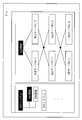
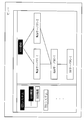
- FIG. 12 shows a view 61 in the case of the second embodiment.
- the view 61 is displayed instead of the view 3 in FIG. 1 of the first embodiment.
- FIG. 12 shows that as a result of performing the processing of FIG. 11 and analyzing a plurality of configuration management tables 205, the DB server # 1 is commonly used for the AAA function of the XXX system and the CCC function of the YYY system. Detected and illustrated.
- the display unit 29 reads the two configuration management tables 205 corresponding to the business system names recorded by the design information integration unit 26 from the configuration management database 28, and also stores the two configuration management tables 205 in the two configuration management tables 205.
- Two corresponding dependency relationship tables 202 are read from the configuration management database 28, and information on the host name recorded by the design information integration unit 26 is read. Then, as in the first embodiment, the display unit 29 uses the configuration management table 205 and the dependency relationship table 202 for each business system, and uses the active device and the standby device for each system component. In addition to showing the redundancy method, a drawing showing the dependency between system components is performed, and the same system component (DB server # 1 in the example of FIG. 12) is duplicated in two business systems. Draw to indicate that.
- the relationship between redundancy of system components of multiple business systems and the type of redundancy can be displayed as a view. It becomes. For this reason, even when system components are shared by multiple business systems, whether a system component failure has an effect on the operation of the business system, whether to switch to a redundant system, whether manual action is required, etc. Judgment can be made and a system failure can be quickly dealt with.
- the design information input unit can input design information of a plurality of business systems, and the design information integration unit analyzes the system component elements commonly used among business systems.
- a possible system configuration information dependency generation system has been described.
- Embodiment 3 In the first and second embodiments described above, the details of redundancy are determined using the CFIA analysis table (FIG. 5) and the host name / IP address correspondence table (FIG. 7). Next, an example using the naming convention of the host name is shown.
- FIG. 13 shows an example of naming rules for host names.
- the first 3 digits indicate the business type
- the 4th to 8th digits indicate the installation location
- the 9th to 10th digits indicate arbitrary numerical values.
- the partner for redundancy can be determined by performing the matching process for the first three digits. That is, the design information integration unit 26 can determine a device having a common first three digit value as a redundant partner.
- Example 2 indicates the installation location in the first to fifth digits, and the business type in the sixth to eighth digits.
- a host name naming rule table shown in FIG. 14 is prepared in the design information storage unit 24, reflecting such a host name naming rule.
- host name naming rule table for each business system, as a naming rule, it is defined what keyword is assigned to which digit of the host name.
- a host name having “web” or “app” in one to three digits is extracted to determine a redundant partner.
- the host name naming rule table of FIG. 14 is used in place of the host name / IP address correspondence table 204 of the first embodiment or together with the host name / IP address correspondence table 204.
- the design information integration unit 26 selects the device paired with the redundancy source device (main system component) extracted in S408 as the redundant partner extracted in S409.
- the host name naming rule table of FIG. 14 is used. Other operations are the same as those in the first embodiment.
- the system configuration information dependency generation system has been described in which the design information input unit receives a plurality of types of design information, and the design information integration unit improves the discrimination accuracy of the redundant configuration combination. .
- Embodiment 4 FIG. In the first and second embodiments, the details of redundancy are determined using the CFIA analysis table (FIG. 5) and the host name / IP address correspondence table (FIG. 7). An example using a list of software installed in each device is shown.
- a software list table indicating a list of installed software is prepared in the design information storage unit 24 for each device (host name) as shown in FIG.
- “OS” indicates an operating system
- “MW” indicates middleware
- “APP” indicates an application program.
- the item with a check is software installed in the device.
- the software list table of FIG. 15 is used instead of the host name / IP address correspondence table 204 of the first embodiment or together with the host name / IP address correspondence table 204.
- the design information integration unit 26 selects the device paired with the redundancy source device (main system component) extracted in S408 as the redundant partner extracted in S409.
- the software list table of FIG. 15 is used.
- the design information integration unit 26 extracts a device in which the same software group as that installed in the redundancy source device is installed from the software list table, and pairs the extracted device with the redundancy source device. Equipment. Other operations are the same as those in the first embodiment.
- the system configuration information dependency generation system has been described in which the design information input unit receives a plurality of types of design information, and the design information integration unit improves the discrimination accuracy of the redundant configuration combination. .
- Embodiment 5 FIG. In the first to fourth embodiments described above, the system design information is held in the configuration management apparatus 2, but in the fifth embodiment, the system design information is held in an external document management system. An example is shown.
- FIG. 16 is a system configuration diagram according to the present embodiment.
- the document management system 91 collectively manages system design information of a plurality of business systems.
- the document management system 91 includes a design information change detection unit 92.
- the design information change detection unit 92 detects a change in the system design information.
- the configuration management device 2 includes a design information communication unit 93.
- the design information communication unit 93 communicates with the design information change detection unit 92.
- the design information change detection unit 92 detects a change in the system design information
- the design information change detection unit 92 notifies the design information communication unit 93 on the configuration management apparatus 2 and re-imports the system design information (re-execution of S405 to S412 in the flow of FIG. 8). Execute).
- the system dependency, redundancy partner, and redundancy method in the latest system design information can be displayed in the view when a system failure occurs, and the failure response can be accurately performed. It becomes possible to carry out.
- the present embodiment has described the system configuration information dependency generation system that automatically updates the system component dependency by detecting the update of the design information stored in the external document management system. .
- Embodiment 6 In the first to fifth embodiments described above, only the dependency relationship between system components is generated and displayed. However, in the sixth embodiment, an example in which the system fault monitoring information is further linked. Show.
- FIG. 17 is a system configuration diagram according to the present embodiment.
- the fault monitoring system 101 includes a system fault monitoring unit 102 that monitors faults in the information system 1, a fault information database 103 that stores fault information (example of monitoring result information) when a fault is detected as a result of monitoring, and a fault It has a failure information notification unit 104 that notifies information to the outside.
- the failure monitoring system 101 corresponds to an example of a monitoring device.
- the configuration management apparatus 2 is provided with a failure information communication unit 105.
- the failure information communication unit 105 receives failure information from the failure monitoring system 101.
- the failure information communication unit 105 corresponds to an example of a monitoring result information receiving unit.
- the system fault monitoring unit 102 on the fault monitoring system 101 detects a fault by communication by polling to the information system 1 or a notification from a server device or a network device, and details of the fault (host name) detected in the fault information database 103. Log fault messages).
- the failure information notification unit 104 detects the update of the failure information database 103 and notifies the failure information communication unit 105 on the configuration management apparatus 2 of the contents.
- the display unit 29 displays the information on the view 3 in consideration of the failure occurrence status of the system components in addition to the information of the first embodiment. In view 3, in addition to the information of the first embodiment, the device in which the failure has occurred and whether or not the device has been switched due to the occurrence of the failure are displayed. In the example of view 3 in FIG.
- a device that is highlighted (white on a black background) is not currently in service
- a device that is displayed as “ERROR” is a device that has failed
- “STAND- A device displayed as “BY” is an alternative device having a redundant configuration and is a standby device.
- the Web server # 1-1 and Web server # 1-2 are operating correctly due to load balancing, a failure occurs in the App server # 1-1, and the server is switched to the App server # 1-2 correctly. It can be seen that DB server # 1-1 is operating correctly and DB server # 1-2, which is a manual substitute device, is in a standby state.
- the points to be dealt with as a failure response can be clarified, and the failure response can be implemented quickly.
- the failure information of the system component from the failure monitoring system is received and the configuration management database information is displayed, the failure location and the switching presence / absence of the redundant configuration are displayed.
- the dependency generation system was explained.
- FIG. 20 is a diagram illustrating an example of hardware resources of the configuration management apparatus 2 described in the first to sixth embodiments. 20 is merely an example of the hardware configuration of the configuration management device 2, and the hardware configuration of the configuration management device 2 is not limited to the configuration illustrated in FIG. Also good.
- the configuration management apparatus 2 includes a CPU 911 (also referred to as a central processing unit, a central processing unit, a processing unit, a processing unit, a microprocessor, a microcomputer, and a processor) that executes a program.
- the CPU 911 is connected to, for example, a ROM (Read Only Memory) 913, a RAM (Random Access Memory) 914, a communication board 915, a display device 901, a keyboard 902, a mouse 903, and a magnetic disk device 920 via a bus 912. Control hardware devices.
- the CPU 911 may be connected to an FDD 904 (Flexible Disk Drive), a compact disk device 905 (CDD), a printer device 906, and a scanner device 907.
- FDD 904 Flexible Disk Drive
- CDD compact disk device
- printer device 906 printer device 907
- a storage device such as an SSD (Solid State Drive), an optical disk device, or a memory card (registered trademark) read / write device may be used.
- the RAM 914 is an example of a volatile memory.
- the storage media of the ROM 913, the FDD 904, the CDD 905, and the magnetic disk device 920 are an example of a nonvolatile memory. These are examples of the storage device.
- the “component management table storage unit 22”, “design information storage unit 24”, and “configuration management database 28” described in the first to sixth embodiments are realized by the RAM 914, the magnetic disk device 920, and the like.
- a communication board 915, a keyboard 902, a mouse 903, a scanner device 907, and the like are examples of input devices.
- the communication board 915, the display device 901, the printer device 906, and the like are examples of output devices.
- the communication board 915 is connected to the network.
- the communication board 915 is connected to a LAN (local area network), the Internet, a WAN (wide area network), a SAN (storage area network), and the like.
- the magnetic disk device 920 stores an operating system 921 (OS), a window system 922, a program group 923, and a file group 924.
- the programs in the program group 923 are executed by the CPU 911 using the operating system 921 and the window system 922.
- the RAM 914 temporarily stores at least part of the operating system 921 program and application programs to be executed by the CPU 911.
- the RAM 914 stores various data necessary for processing by the CPU 911.
- the ROM 913 stores a BIOS (Basic Input Output System) program
- the magnetic disk device 920 stores a boot program.
- BIOS Basic Input Output System
- the configuration management device 2 is activated, the BIOS program in the ROM 913 and the boot program in the magnetic disk device 920 are executed, and the operating system 921 is activated by the BIOS program and the boot program.
- the program group 923 stores programs that execute the functions described as “-unit” (other than “-storage unit” in the following) in the description of the first to sixth embodiments.
- the program is read and executed by the CPU 911.
- the encryption key / decryption key, random number value, and parameter may be stored as a file in a storage medium such as a disk or memory.
- the “ ⁇ file” and “ ⁇ database” are stored in a storage medium such as a disk or memory.
- Information, data, signal values, variable values, and parameters stored in a storage medium such as a disk or memory are read out to the main memory or cache memory by the CPU 911 via a read / write circuit.
- the read information, data, signal value, variable value, and parameter are used for CPU operations such as extraction, search, reference, comparison, calculation, calculation, processing, editing, output, printing, and display.
- Information, data, signal values, variable values, and parameters are stored in the main memory, registers, cache memory, and buffers during the CPU operations of extraction, search, reference, comparison, calculation, processing, editing, output, printing, and display. It is temporarily stored in a memory or the like.
- the arrows in the flowcharts described in the first to sixth embodiments mainly indicate input / output of data and signals.
- Data and signal values are recorded in a storage medium such as a memory of the RAM 914, a flexible disk of the FDD 904, a compact disk of the CDD 905, a magnetic disk of the magnetic disk device 920, other optical disks, mini disks, and DVDs.
- Data and signals are transmitted online via a bus 912, signal lines, cables, or other transmission media.
- the “information system management method” can be realized by the steps, procedures, and processes shown in the flowcharts described in the first to sixth embodiments.
- the “ ⁇ unit” may be realized by firmware stored in the ROM 913. Alternatively, it may be implemented only by software, or only by hardware such as elements, devices, substrates, and wirings, by a combination of software and hardware, or by a combination of firmware.
- Firmware and software are stored as programs in a storage medium such as a magnetic disk, a flexible disk, an optical disk, a compact disk, a mini disk, and a DVD.
- the program is read by the CPU 911 and executed by the CPU 911. That is, the program causes the computer to function as the “ ⁇ unit” in the first to sixth embodiments. Alternatively, the procedure or method of “—unit” in the first to sixth embodiments is executed by a computer.
- the configuration management device 2 described in the first to sixth embodiments includes a CPU as a processing device, a memory as a storage device, a magnetic disk, a keyboard as an input device, a mouse, a communication board, a display device as an output device, and a communication device.
- a computer including a board or the like.
- the functions indicated as “ ⁇ units” are realized using these processing devices, storage devices, input devices, and output devices.
Abstract
Description
また、構成管理装置が、クライアント(端末)からサーバ上のソフトウェアサービスへの接続を監視して、情報システムの機器間の依存関係を自動的に収集・蓄積方法も提案されている(例えば、特許文献3)。
しかし、機器間の冗長化構成の組み合わせと冗長化の種類を判別するためには、冗長化の仕組みを持つソフトウェア等の設定情報を解析する機構を用意するか、人手で冗長化の組み合わせや種類を入力する等の必要があり、実現が困難であるか又は運用負荷が高いという課題があった。
複数のシステム構成要素を含み、各システム構成要素で2つ以上のコンポーネントを用いた冗長化が実施されている情報システムを管理する情報システム管理装置であって、
各システム構成要素で稼動中のコンポーネントとの通信により生成された、各システム構成要素で稼動中のコンポーネントと、システム構成要素間の依存関係とが記述される依存関係情報を入力する依存関係情報入力部と、
各システム構成要素における冗長化の詳細が記述される冗長化詳細情報を入力する冗長化詳細情報入力部と、
前記依存関係情報に記述される各システム構成要素で稼動中のコンポーネントに対して、前記冗長化詳細情報に記述される冗長化の詳細を関係付ける情報関係付け部と、
前記依存関係情報に記述される、各システム構成要素で稼動中のコンポーネントとシステム構成要素間の依存関係とを表示するとともに、前記情報関係付け部による関係付けに基づき、各システム構成要素で稼動中のコンポーネントの表示に対応付けて各システム構成要素における冗長化の詳細を表示する表示部とを有することを特徴とする。
実施の形態1~6に係る構成管理装置は、システム構成要素の依存関係の生成に対して、システム構成要素における冗長化の組み合わせと種類を自動的に判別し、判別した冗長化の組み合わせと種類をユーザに対して表示することを主な目的としている。
冗長化構成には、ロードバランス、フェイルオーバクラスタ、コールドスタンバイ等の手法がある。
ロードバランスは、2台以上の機器が常時サービス提供しており1台が故障しても他の機器で代替動作するものである。
フェイルオーバクラスタは、本番系機器に対して自動切換可能な待機系機器を用意し、本番系の故障時に待機系機器に自動的に切り替わって代替動作するものである。
コールドスタンバイは、本番系機器に対して通常時は動作を停止している代替機器を用意し、本番系の故障時には代替機器を手動で起動して代替動作させるものである。
構成管理装置2は、情報システム管理装置の例に相当する。
より具体的には、構成管理装置2は情報システム1からシステム構成要素の情報を収集して依存関係を分析・保存する。
情報システム1はネットワーク、サーバ装置、端末装置等で構成される。
構成管理装置2が管理する情報システム1は、図2のビュー3に示すように、例えば、XXXシステム、YYYシステム等から構成され、また、XXXシステムにはAAA機能とBBB機能が配備されているものとする。
図2は、XXXシステムのAAA機能における機器構成を示している。
図2に示すように、XXXシステムのAAA機能では、Webサーバ#1-1、Webサーバ#1-2、Appサーバ#1-1、Appサーバ#1-2、DBサーバ#1-1、DBサーバ#1-2が存在している。
Webサーバ#1-1、Webサーバ#1-2における「Webサーバ#1」、Appサーバ#1-1、Appサーバ#1-2における「Appサーバ#1」、DBサーバ#1-1、DBサーバ#1-2における「DBサーバ#1」は、それぞれシステム構成要素を示している。
そして、Webサーバ#1-1、Webサーバ#1-2は、システム構成要素「Webサーバ#1」において冗長化に用いられるコンポーネントである。
同様に、Appサーバ#1-1、Appサーバ#1-2は、システム構成要素「Appサーバ#1」において冗長化に用いられるコンポーネントである。
同様に、DBサーバ#1-1、DBサーバ#1-2は、システム構成要素「DBサーバ#1」において冗長化に用いられるコンポーネントである。
このように、構成管理装置2が管理する情報システム1は、複数のシステム構成要素を含み、各システム構成要素が2つ以上のコンポーネントを用いて冗長化されている。
なお、コンポーネントを機器ともいう。
そして、情報システム1内で稼働中のコンポーネントと、システム構成要素間の依存関係が示される動作機器一覧テーブル201と依存関係テーブル202を生成し、生成した動作機器一覧テーブル201と依存関係テーブル202を構成要素管理テーブル記憶部22に格納する。
動作機器一覧テーブル201は図3に例示するテーブルであり、情報システム1内で動作中のコンポーネントが記述されている。
依存関係テーブル202は図4に例示するテーブルであり、システム構成要素間の依存関係が記述されている。
動作機器一覧テーブル201と依存関係テーブル202の詳細は、図3、図4を参照して後述する。
依存関係テーブル202は依存関係情報の例に相当する。
CFIA分析表203は図5に例示するテーブルであり、情報システム1に含まれる全てのコンポーネントが記述されている。
つまり、CFIA分析表203には、各システム構成要素の主系のコンポーネントだけでなく、待機系のコンポーネントも記述されている。
また、CFIA分析表203には、各システム構成要素における冗長化の詳細が記述されている。
例えば、CFIA分析表203に示す「L」、「F」、「M」は冗長化の方式であり、L(Load Balance)はロードバランスによる冗長化、F(Failover)はフェイルオーバによる冗長化、M(Manual)は手動切り替え(コールドスタンバイ)による冗長化を表す。
ホスト名・IPアドレス対応表204は図6に例示するテーブルであり、各コンポーネントの通信アドレス(IPアドレス)が記述されている。
CFIA分析表203、ホスト名・IPアドレス対応表204の詳細は、図5、図6を参照して後述する。
CFIA分析表203は冗長化詳細情報の例、ホスト名・IPアドレス対応表204は通信アドレス情報の例に相当する。
設計情報入力部25は冗長化詳細情報入力部の例に相当する。
より具体的には、設計情報統合部26は、図7に例示する構成管理テーブル205を生成する。
構成管理テーブル205内の「冗長化」に記載されている値と「ホスト名」に記載されている値により、システム構成要素ごとに、待機中のコンポーネントが、依存関係テーブル202に記述されている稼動中のコンポーネントに関係付けられることになる。
また、構成管理テーブル205内の「AAA機能」に記載されている冗長化の方式を表す記号(「L」、「F」、「M」)と「ホスト名」に記載されている値により、システム構成要素ごとに、冗長化の方式が、依存関係テーブル202に記述されている稼動中のコンポーネントに関係付けられることになる。
構成管理テーブル205の詳細は、図7を参照して後述する。
また、設計情報統合部26は、情報関係付け部の例に相当する。
「機器名」に示されている機器は、前述したように、構成情報収集部21が情報システム1に含まれる各機器との通信により検出したコンポーネントの名称である。
また、「ホスト名」は、「機器名」に示されるコンポーネントのID(Identifier)である。
「ホスト名」に示されているIDは、図3の動作機器一覧テーブル201の「ホスト名」に示されているものと同様である。
つまり、構成情報収集部21により検出された稼動中のコンポーネントのIDである。
「依存先」に示されているIDは、「ホスト名」のIDに対応するコンポーネントが、稼動する上で依存しているコンポーネントのIDである。
つまり、webabc(Webサーバ#1-1)とwebdef(Webサーバ#1-2)は、稼動する上で、appabc(Appサーバ#1-1)のリソースをなんらかの形で利用している。
また、appabc(Appサーバ#1-1)は、dbsac(DBサーバ#1-1)に依存している。
前述したように、依存関係テーブル202も、構成情報収集部21により生成される。
なお、動作機器一覧テーブル201は依存関係テーブル202を生成する際に用いられるが、設計情報統合部26及び表示部29の処理では、動作機器一覧テーブル201は必ずしも必要ではなく、依存関係テーブル202があればよい。
このため、構成要素管理テーブル記憶部22には依存関係テーブル202のみが格納されるようにしてもよい。
また、依存関係テーブル202は、従来のCMDBの情報であってもよい。
図5は、情報システム設計時に実施するCFIA(Component Failure Impact Analysis:コンポーネント障害インパクト分析)の分析表の例を示したものである。
図5の表は1つの業務システムのCFIA分析結果を示したものであり、各機器に対して、ホスト名、機器が故障した場合の機能(図5中ではAAA機能、BBB機能)に対する影響、システム構成要素の障害検知方法、を整理したものである。
機器が故障した場合の機能に対する影響は、冗長化の方式(例えばL、F、M)の記号で表す。
前述したように、Lはロードバランスによる冗長化、Fはフェイルオーバによる冗長化、Mは手動切り替えによる冗長化を示す。
空欄の場合は該当する機器が故障してもその機能に対する影響がないことを示す。
障害検知方法の欄は、例えばS、P等の記号で表し、S(Server surveillance)はサーバ監視システムによる検知、N(Network surveillance)はネットワーク監視システムによる検知を示す。
図6は、ホスト名とIPアドレスの対応表であり、機器のホスト名からIPアドレスを参照できるように記述されている。
図7に示す構成管理テーブル205では、CFIA分析表203と比較して、「冗長化」の項目が追加されている。
「冗長化」内のIDと「ホスト名」内のIDにより、システム構成要素ごとに、冗長化に用いられている2つ以上のコンポーネントのうちの待機中のコンポーネントと、依存関係テーブル202(図4)に記述されている稼動中のコンポーネントとが関係付けられることになる。
例えば、構成管理テーブル205において、依存関係テーブル202で稼動中となっているappabc(Appサーバ#1-1)と、待機中のappdef(Appサーバ#1-2)とが関係づけられる。
また、「AAA機能」に記載されている冗長化の方式を表す記号(「L」、「F」、「M」)と「ホスト名」に記載されている値により、システム構成要素ごとに、冗長化の方式と、依存関係テーブル202に記述されている稼動中のコンポーネントとが関係付けられることになる。
例えば、構成管理テーブル205において、依存関係テーブル202で稼動中となっているappabc(Appサーバ#1-1)と、冗長化の方式「F」とが関係付けられる。
ビュー3では、各システム構成要素で稼動中のコンポーネントとシステム構成要素間の依存関係とが表示されるとともに、設計情報統合部26で生成された構成管理テーブル205に基づき、各システム構成要素で稼動中のコンポーネントの表示に対応付けて各システム構成要素における冗長化の詳細が表示される。
冗長化の詳細としては、各システム構成要素での冗長化の方式(L、F、M)と、各システム構成要素で待機中のコンポーネントが示される。
依存関係テーブル202のみを用いると、図19に例示するビューが生成される。
つまり、情報システム1で稼動中のコンポーネントと、コンポーネント(システム構成要素)間の依存関係が示されるのみである。
これに対して、本実施の形態では、稼動中のコンポーネントと、コンポーネント(システム構成要素)間の依存関係の表示に加えて、稼動中のコンポーネントに対して冗長化の方式と待機中のコンポーネントが表示される。
次に、依存関係情報入力部23が、収集したシステム構成要素について、各システム構成要素間の通信関係からシステム構成要素間の依存関係を解析し、依存関係テーブル202を生成し、生成した依存関係テーブル202を構成要素管理テーブル記憶部22に保管する。
構成情報収集部21、構成要素管理テーブル記憶部22の構成及び動作については、特許文献1~3、非特許文献1いずれの方式に従ってもよい。
次に、設計情報入力部25が、設計情報記憶部24からCFIA分析表203を読み出す。
データベース登録部27は、設計情報統合部26が生成した構成管理テーブル205と依存関係テーブル202を構成管理データベース28に登録する。
表示部29は構成管理データベース28の構成管理テーブル205と依存関係テーブル202の内容を反映させたビュー3を生成し、表示する。
図8は図1の構成管理装置2の動作を説明したフローである。
つまり、構成情報収集部21は、システム構成要素の情報を収集し、各種プロトコルの通信状態を確認して、通信の存在する機器を示す動作機器一覧テーブル201と、機器間の依存関係を示す依存関係テーブル202を生成し、生成した動作機器一覧テーブル201と依存関係テーブル202を構成要素管理テーブル記憶部22に保存する。
次に、S405で、設計情報入力部25が、設計情報記憶部24からCFIA分析表203(図5)を読み出し、読み出したCFIA分析表203を設計情報統合部26に渡す。
具体的には、設計情報統合部26は、S406で、CFIA分析表203から記号が“L”の機器を抽出する。
これによってロードバランスで冗長化されている機器の組み合わせが判明するので、組み合わせを記憶する(S407)。
次に、S408で、設計情報統合部26は、CFIA分析表203から記号が“F”及び“M”の機器を抽出し、S409で、記号が空欄の機器を抽出する。
ここで、記号が空白の行はその機器が故障してもシステムの機能に影響を与えないことを示すので、この行は代替機(スタンバイ機)であることが判断でき、記号が“F”又は“M”の機器に対する冗長化の相手であることがわかる。
次に、S410で、設計情報入力部25が、設計情報記憶部24からホスト名・IPアドレス対応表204(図6)を読み出し、読み出したホスト名・IPアドレス対応表204を設計情報統合部26に渡す。
次に、設計情報統合部26は、S411で、S408で抽出した冗長化元の機器(主系コンポーネント)と、S409で抽出した冗長化相手の機器(待機系コンポーネント)において、同じネットワークセグメントに存在している組み合わせを検索し、冗長化のペアを確定する。
例えば、図5のAppサーバ#1-1の冗長化相手の機器を抽出する場合を考える。
Appサーバ#1-1のIPアドレスは、図6に示すように「XXX.YYY.MMM.CCC」である。
設計情報統合部26は、このIPアドレスのネットワークセグメント「XXX.YYY.MMM.」と一致するネットワークセグメントを有するIPアドレス「XXX.YYY.MMM.EEE」を抽出し、このIPアドレスが「ホスト名:appdef」の機器のIPアドレスであると判断する。
この結果、設計情報統合部26は、Appサーバ#1-1の冗長化相手の機器が、Appサーバ#1-2である旨を構成管理テーブル205に記述することができる。
表示部29は、依存関係テーブル202から、各システム構成要素で稼働中の機器とシステム構成要素間の依存関係を表す描画を行い、また、稼働中の機器に対して、構成管理テーブル205に示される冗長化の方式と、待機中の機器とを対応付けて描画して、図2のビュー3を表示する。
このため、機器の障害発生時に、業務システムの稼動に対する影響有無、冗長化システムへの切り替え有無、手動対処の要否等の判断を行うことができ、システム障害への対処を迅速に行うことができる。
以下の手段を備え、システム設計情報を取り込むことによりシステム冗長構成の組み合わせと種類を判別する、システム構成情報の依存関係生成システムを説明した。
(a)情報システム環境と通信を行ってシステム構成要素の情報を収集する、構成情報収集部;
(b)収集したシステム構成要素の情報を保管する、構成要素管理テーブル;
(c)システム構成要素から収集した情報より生成された、システム構成要素間の依存関係の情報を入力する、依存関係情報入力部;
(d)情報システムの設計情報を入力する、設計情報入力部;
(e)(c)の依存関係にシステム設計情報から抽出した冗長構成の組み合わせと種類を統合する、設計情報統合部;
(f)(e)で生成した情報をデータベースに保存する、データベース登録部;
(g)収集されたシステム構成要素の情報と生成したシステム構成要素間の依存関係の情報を保存する、構成管理データベース;
(h)構成管理データベースの情報を利用者に表示する、表示部。
以上の実施の形態1では、1つのCFIA分析表(図5)を用いて1つの業務システムについて冗長化の詳細を確定するようにしている。
本実施の形態では、2つ以上のCFIA分析表を用いて複数の業務システムについて冗長化の詳細を確定する例を示す。
図11の中のS501、S502以外の部分は図8と同様であるので、説明を省略する。
S411までの処理で1つのCFIA分析表(1つの業務システム)に対してシステム構成要素の冗長化ペアを確定した後、設計情報入力部25がS501で他の業務システムのCFIA分析表を読み込む。
次に、S502で、1つ目のCFIA分析表と比較して同一のホスト名が存在する場合は、設計情報統合部26は、CFIA分析表の業務システム名と、ホスト名を記録し、S412で構成管理データベース28に記録した情報を登録する。
つまり、設計情報統合部26は、各業務システムの情報システム1に対して構成管理テーブル205を生成し、生成した構成管理テーブル205を比較し、2つの構成管理テーブル205に同一のホスト名が含まれていれば、2つの構成管理テーブル205に含まれているホスト名と、2つの構成管理テーブル205が対象としている業務システムの業務システム名をデータベース登録部27を介して構成管理データベース28に記録し、また、2つの構成管理テーブル205をデータベース登録部27を介して構成管理データベース28に格納する。
また、設計情報統合部26はデータベース登録部27を介して依存関係テーブル202も構成管理データベース28に格納する。
なお、この例では2つの構成管理テーブル205を対応付ける例を示したが、3つ以上の構成管理テーブル205を対応付ける場合も同様の処理となる。
ビュー61は実施の形態1の図1におけるビュー3の代わりに表示されるものである。
図12は、図11の処理を行い、複数の構成管理テーブル205の分析を行った結果、DBサーバ#1がXXXシステムのAAA機能と、YYYシステムのCCC機能で共通で利用されていることを検出し、図示したものである。
本実施の形態では、表示部29は、設計情報統合部26により記録された業務システム名に対応する2つの構成管理テーブル205を構成管理データベース28から読み出し、また、この2つの構成管理テーブル205に対応する2つの依存関係テーブル202を構成管理データベース28から読み出し、また、設計情報統合部26により記録されたホスト名の情報を読み出す。
そして、表示部29は、実施の形態1と同様に、各業務システムに対して、構成管理テーブル205と依存関係テーブル202を用いて、システム構成要素ごとに稼働中の機器と待機中の機器と冗長化の方式を示すとともに、システム構成要素間の依存関係を示す描画を行い、更に、同一のシステム構成要素(図12の例ではDBサーバ#1)が2つの業務システムに重複して含まれることを示す描画を行う。
このため、複数の業務システムでシステム構成要素を共用していた場合でも、システム構成要素の障害発生時に、業務システムの稼動に対する影響有無、冗長化システムへの切り替え有無、手動対処の要否等の判断を行うことができ、システム障害への対処を迅速に行うことができる。
以上の実施の形態1及び実施の形態2では、CFIA分析表(図5)とホスト名・IPアドレス対応表(図7)を用いて冗長化の詳細を確定するようにしたものであるが、次に、ホスト名の命名規則を利用した例を示す。
例1は先頭3桁が業務種類、4桁目~8桁目が設置場所、9桁目~10桁目は任意の数値を示すものである。
例1の場合、先頭3桁のマッチング処理を行うことで、冗長化の相手を確定させることができる。
つまり、設計情報統合部26は、先頭3桁の値が共通する機器を、冗長化の相手と判断することができる。
例2は、1~5桁目に設置場所、6~8桁目に業務種類を示す。
本実施の形態では、このようなホスト名の命名規則を反映させて、図14に示す、ホスト名命名規則表を設計情報記憶部24内に用意する。
ホスト名命名規則表では、業務システム毎に、命名規則として、ホスト名のどの桁からどの桁にどの様なキーワードを付けるかを規定する。
XXXシステムでは、1~3桁に「web」や「app」とあるホスト名を抽出して、冗長化の相手を確定することになる。
つまり、本実施の形態では、図8のS411において、設計情報統合部26が、S408で抽出した冗長化元の機器(主系コンポーネント)とペアになる機器を、S409で抽出した冗長化相手の機器(待機系コンポーネント)の中から選択する際に、図14のホスト名命名規則表が用いられる。
その他の動作は、実施の形態1と同じである。
実施の形態1及び実施の形態2では、CFIA分析表(図5)とホスト名・IPアドレス対応表(図7)を用いて冗長化の詳細を確定するようにしたものであるが、次に、各機器に実装されているソフトウェアの一覧を利用した例を示す。
本実施の形態では、図15に示すような、機器(ホスト名)ごとに、実装されているソフトウェアの一覧を示すソフトウェア一覧テーブルを設計情報記憶部24内に用意する。
図15において、「OS」はオペレーティングシステムを示し、「MW」はミドルウェアを示し、「APP」はアプリケーションプログラムを示す。
また、チェックが付されている項目が、機器に実装されているソフトウェアである。
つまり、本実施の形態では、図8のS411において、設計情報統合部26が、S408で抽出した冗長化元の機器(主系コンポーネント)とペアになる機器を、S409で抽出した冗長化相手の機器(待機系コンポーネント)の中から選択する際に、図15のソフトウェア一覧テーブルが用いられる。
設計情報統合部26は、冗長化元の機器に実装されているソフトウェア群と同じソフトウェア群が実装されている機器をソフトウェア一覧テーブルから抽出し、抽出した機器を、冗長化元の機器とペアとなる機器とする。
その他の動作は、実施の形態1と同じである。
以上の実施の形態1~実施の形態4では、システム設計情報を構成管理装置2の中に持つこととしたものであるが、実施の形態5では、システム設計情報を外部の文書管理システムに持つ例を示す。
文書管理システム91は、複数の業務システムのシステム設計情報を一括して管理する。
文書管理システム91には、設計情報変更検知部92が含まれる。
設計情報変更検知部92は、システム設計情報における変更を検知する。
また、構成管理装置2には、設計情報通信部93が含まれる。
設計情報通信部93は、設計情報変更検知部92と通信を行う。
設計情報変更検知部92がシステム設計情報の変更を検知した場合、構成管理装置2上の設計情報通信部93に通知し、システム設計情報の再取り込み(図8のフローの、S405~S412の再実行)を実施する。
以上の実施の形態1~実施の形態5では、システム構成要素の依存関係のみを生成・表示することとしたものであるが、実施の形態6では、さらにシステム障害の監視情報と連携した例を示す。
図17において、101~105以外の要素は図1と同様であり、説明を省略する。
障害監視システム101は、情報システム1の障害を監視するシステム障害監視部102と、監視した結果、障害を検出した場合に障害情報(監視結果情報の例)を格納する障害情報データベース103と、障害情報を外部に通知する障害情報通知部104を持つ。
障害監視システム101は、監視装置の例に相当する。
また、構成管理装置2には障害情報通信部105を設ける。
障害情報通信部105は、障害監視システム101から障害情報を受信する。
障害情報通信部105は、監視結果情報受信部の例に相当する。
障害情報通知部104は、障害情報データベース103の更新を検知し、構成管理装置2上の障害情報通信部105に内容を通知する。
表示部29は、実施の形態1の情報に加えて、システム構成要素の障害発生状況を加味して、ビュー3に情報を表示する。
ビュー3には、実施の形態1の情報に加えて、障害が発生した機器、障害発生による機器の切り替えの有無が表示される。
図18のビュー3の例では、反転表示(黒地に白字)になっている機器が現在サービスしていない機器、「ERROR」と表示されている機器は障害が発生している機器、「STAND-BY」と表示されている機器が冗長構成による代替機器で待機状態の機器を示す。
この例では、Webサーバ#1-1、Webサーバ#1-2はロードバランスにより正しく動作していること、Appサーバ#1-1に障害が発生し、Appサーバ#1-2に正しく切り替わっていること、DBサーバ#1-1は正しく稼動しており手動による代替機であるDBサーバ#1-2は待機状態にあることがわかる。
図20は、実施の形態1~6に示す構成管理装置2のハードウェア資源の一例を示す図である。
なお、図20の構成は、あくまでも構成管理装置2のハードウェア構成の一例を示すものであり、構成管理装置2のハードウェア構成は図20に記載の構成に限らず、他の構成であってもよい。
CPU911は、バス912を介して、例えば、ROM(Read Only Memory)913、RAM(Random Access Memory)914、通信ボード915、表示装置901、キーボード902、マウス903、磁気ディスク装置920と接続され、これらのハードウェアデバイスを制御する。
更に、CPU911は、FDD904(Flexible Disk Drive)、コンパクトディスク装置905(CDD)、プリンタ装置906、スキャナ装置907と接続していてもよい。また、磁気ディスク装置920の代わりに、SSD(Solid State Drive)、光ディスク装置、メモリカード(登録商標)読み書き装置などの記憶装置でもよい。
RAM914は、揮発性メモリの一例である。ROM913、FDD904、CDD905、磁気ディスク装置920の記憶媒体は、不揮発性メモリの一例である。これらは、記憶装置の一例である。
実施の形態1~6で説明した「構成要素管理テーブル記憶部22」、「設計情報記憶部24」、「構成管理データベース28」は、RAM914、磁気ディスク装置920等により実現される。
通信ボード915、キーボード902、マウス903、スキャナ装置907などは、入力装置の一例である。
また、通信ボード915、表示装置901、プリンタ装置906などは、出力装置の一例である。
例えば、通信ボード915は、LAN(ローカルエリアネットワーク)、インターネット、WAN(ワイドエリアネットワーク)、SAN(ストレージエリアネットワーク)などに接続されている。
プログラム群923のプログラムは、CPU911がオペレーティングシステム921、ウィンドウシステム922を利用しながら実行する。
また、RAM914には、CPU911による処理に必要な各種データが格納される。
構成管理装置2の起動時には、ROM913のBIOSプログラム及び磁気ディスク装置920のブートプログラムが実行され、BIOSプログラム及びブートプログラムによりオペレーティングシステム921が起動される。
また、暗号鍵・復号鍵や乱数値やパラメータが、ディスクやメモリなどの記憶媒体にファイルとして記憶されてもよい。
「~ファイル」や「~データベース」は、ディスクやメモリなどの記憶媒体に記憶される。
ディスクやメモリなどの記憶媒体に記憶された情報やデータや信号値や変数値やパラメータは、読み書き回路を介してCPU911によりメインメモリやキャッシュメモリに読み出される。
そして、読み出された情報やデータや信号値や変数値やパラメータは、抽出・検索・参照・比較・演算・計算・処理・編集・出力・印刷・表示などのCPUの動作に用いられる。
抽出・検索・参照・比較・演算・計算・処理・編集・出力・印刷・表示のCPUの動作の間、情報やデータや信号値や変数値やパラメータは、メインメモリ、レジスタ、キャッシュメモリ、バッファメモリ等に一時的に記憶される。
また、実施の形態1~6で説明しているフローチャートの矢印の部分は主としてデータや信号の入出力を示す。
データや信号値は、RAM914のメモリ、FDD904のフレキシブルディスク、CDD905のコンパクトディスク、磁気ディスク装置920の磁気ディスク、その他光ディスク、ミニディスク、DVD等の記憶媒体に記録される。
また、データや信号は、バス912や信号線やケーブルその他の伝送媒体によりオンライン伝送される。
すなわち、実施の形態1~6で説明したフローチャートに示すステップ、手順、処理により、本発明に係る「情報システム管理方法」を実現することができる。
また、「~部」として説明しているものは、ROM913に記憶されたファームウェアで実現されていても構わない。
或いは、ソフトウェアのみ、或いは、素子・デバイス・基板・配線などのハードウェアのみ、或いは、ソフトウェアとハードウェアとの組み合わせ、さらには、ファームウェアとの組み合わせで実施されても構わない。
ファームウェアとソフトウェアは、プログラムとして、磁気ディスク、フレキシブルディスク、光ディスク、コンパクトディスク、ミニディスク、DVD等の記憶媒体に記憶される。
プログラムはCPU911により読み出され、CPU911により実行される。
すなわち、プログラムは、実施の形態1~6の「~部」としてコンピュータを機能させるものである。あるいは、実施の形態1~6の「~部」の手順や方法をコンピュータに実行させるものである。
そして、上記したように「~部」として示された機能をこれら処理装置、記憶装置、入力装置、出力装置を用いて実現するものである。
Claims (14)
- 複数のシステム構成要素を含み、各システム構成要素で2つ以上のコンポーネントを用いた冗長化が実施されている情報システムを管理する情報システム管理装置であって、
各システム構成要素で稼動中のコンポーネントとの通信により生成された、各システム構成要素で稼動中のコンポーネントと、システム構成要素間の依存関係とが記述される依存関係情報を入力する依存関係情報入力部と、
各システム構成要素における冗長化の詳細が記述される冗長化詳細情報を入力する冗長化詳細情報入力部と、
前記依存関係情報に記述される各システム構成要素で稼動中のコンポーネントに対して、前記冗長化詳細情報に記述される冗長化の詳細を関係付ける情報関係付け部と、
前記依存関係情報に記述される、各システム構成要素で稼動中のコンポーネントとシステム構成要素間の依存関係とを表示するとともに、前記情報関係付け部による関係付けに基づき、各システム構成要素で稼動中のコンポーネントの表示に対応付けて各システム構成要素における冗長化の詳細を表示する表示部とを有することを特徴とする情報システム管理装置。 - 前記情報システム管理装置は、
実施されている冗長化の方式がシステム構成要素間で一様ではない情報システムを管理し、
前記冗長化詳細情報入力部は、
各システム構成要素における冗長化の詳細として、各システム構成要素における冗長化の方式が記述される冗長化詳細情報を入力し、
前記情報関係付け部は、
前記依存関係情報に記述される各システム構成要素で稼動中のコンポーネントに対して、前記冗長化詳細情報に記述される冗長化の方式を関係付け、
前記表示部は、
前記情報関係付け部による関係付けに基づき、各システム構成要素で稼動中のコンポーネントの表示に対応付けて各システム構成要素における冗長化の方式を表示することを特徴とする請求項1に記載の情報システム管理装置。 - 前記冗長化詳細情報入力部は、
システム構成要素ごとに、冗長化の方式として、ロードバランス、フェイルオーバクラスタ及びコールドスタンバイのうちのいずれかが記述される冗長化詳細情報を入力することを特徴とする請求項2に記載の情報システム管理装置。 - 前記冗長化詳細情報入力部は、
各システム構成要素における冗長化の詳細として、各システム構成要素において冗長化に用いられている2つ以上のコンポーネントが記述される冗長化詳細情報を入力し、
前記情報関係付け部は、
前記依存関係情報に記述される各システム構成要素で稼動中のコンポーネントに対して、前記冗長化詳細情報に記述される2つ以上のコンポーネントうちの休止中のコンポーネントを関係付け、
前記表示部は、
前記情報関係付け部による関係付けに基づき、各システム構成要素の2つ以上のコンポーネントのうちの休止中のコンポーネントを、各システム構成要素で稼動中のコンポーネントの表示に対応付けて表示することを特徴とする請求項1~3のいずれかに記載の情報システム管理装置。 - 前記情報システム管理装置は、
前記複数のシステム構成要素で用いられている複数のコンポーネントの各々に通信アドレスが設定され、同じシステム構成要素で用いられている2つ以上のコンポーネントの間では所定の範囲で通信アドレスが共通している情報システムを管理しており、
前記冗長化詳細情報入力部は、
冗長化に用いられる2つ以上のコンポーネントのうち、主系として用いられる主系コンポーネントは対応するシステム構成要素と関係付けられて記述されているが、待機系として用いられる待機系コンポーネントは対応するシステム構成要素と関係付けられずに記述されている冗長化詳細情報と、
各コンポーネントの通信アドレスが記述される通信アドレス情報とを入力し、
前記情報関係付け部は、
システム構成要素ごとに、主系コンポーネントを前記冗長化詳細情報から抽出し、前記通信アドレス情報に基づき、抽出した主系コンポーネントと、通信アドレスが所定の範囲で共通する待機系コンポーネントを前記冗長化詳細情報から抽出し、
抽出した各システム構成要素の主系コンポーネントと待機系コンポーネントのうちの休止中のコンポーネントを、前記依存関係情報に記述される各システム構成要素で稼動中のコンポーネントに対して関係付け、
前記表示部は、
前記情報関係付け部による関係付けに基づき、各システム構成要素の主系コンポーネントと待機系コンポーネントのうちの休止中のコンポーネントを、各システム構成要素で稼動中のコンポーネントの表示に対応付けて表示することを特徴とする請求項4に記載の情報システム管理装置。 - 前記情報システム管理装置は、
前記複数のシステム構成要素で用いられている複数のコンポーネントの各々にID(Identifier)が設定され、同じシステム構成要素で用いられている2つ以上のコンポーネントの間では所定の範囲でIDが共通している情報システムを管理しており、
前記冗長化詳細情報入力部は、
冗長化に用いられる2つ以上のコンポーネントのうち、主系として用いられる主系コンポーネントは対応するシステム構成要素と関係付けられて記述されているが、待機系として用いられる待機系コンポーネントは対応するシステム構成要素と関係付けられずに記述されている冗長化詳細情報と、
各コンポーネントのIDが記述されるID情報とを入力し、
前記情報関係付け部は、
システム構成要素ごとに、主系コンポーネントを前記冗長化詳細情報から抽出し、前記ID情報に基づき、抽出した主系コンポーネントと、IDが所定の範囲で共通する待機系コンポーネントを前記冗長化詳細情報から抽出し、
抽出した各システム構成要素の主系コンポーネントと待機系コンポーネントのうちの休止中のコンポーネントを、前記依存関係情報に記述される各システム構成要素で稼動中のコンポーネントに対して関係付け、
前記表示部は、
前記情報関係付け部による関係付けに基づき、各システム構成要素の主系コンポーネントと待機系コンポーネントのうちの休止中のコンポーネントを、各システム構成要素で稼動中のコンポーネントの表示に対応付けて表示することを特徴とする請求項4に記載の情報システム管理装置。 - 前記情報システム管理装置は、
前記複数のシステム構成要素で用いられている複数のコンポーネントの各々に複数のソフトウェアが実装され、同じシステム構成要素で用いられている2つ以上のコンポーネントの間では実装されているソフトウェアの組合せが一致し、システム構成要素間では、コンポーネントに実装されているソフトウェアの組合せが異なっている情報システムを管理しており、
前記冗長化詳細情報入力部は、
冗長化に用いられる2つ以上のコンポーネントのうち、主系として用いられる主系コンポーネントは対応するシステム構成要素と関係付けられて記述されているが、待機系として用いられる待機系コンポーネントは対応するシステム構成要素と関係付けられずに記述されている冗長化詳細情報と、
コンポーネントごとに、実装されているソフトウェアの組合せが記述される実装ソフトウェア情報とを入力し、
前記情報関係付け部は、
システム構成要素ごとに、主系コンポーネントを前記冗長化詳細情報から抽出し、前記実装ソフトウェア情報に基づき、実装されているソフトウェアの組合せが、抽出した主系コンポーネントと一致する待機系コンポーネントを前記冗長化詳細情報から抽出し、
抽出した各システム構成要素の主系コンポーネントと待機系コンポーネントのうちの休止中のコンポーネントを、前記依存関係情報に記述される各システム構成要素で稼動中のコンポーネントに対して関係付け、
前記表示部は、
前記情報関係付け部による関係付けに基づき、各システム構成要素の主系コンポーネントと待機系コンポーネントのうちの休止中のコンポーネントを、各システム構成要素で稼動中のコンポーネントの表示に対応付けて表示することを特徴とする請求項4に記載の情報システム管理装置。 - 前記情報システム管理装置は、
各々が冗長化されている複数の情報システムを管理し、
前記依存関係情報入力部は、
情報システムごとに依存関係情報を入力し、
前記冗長化設計情報入力部は、
情報システムごとに冗長化設計情報を入力し、
前記情報関係付け部は、
各情報システムの依存関係情報を比較し、
前記表示部は、
前記情報関係付け部による各情報システムの依存関係情報の比較の結果、2つ以上の情報システムに同一のシステム構成要素が重複して含まれていることが判明した場合に、
同一のシステム構成要素が当該2つ以上の情報システムに重複して含まれていることが表されるようにして、当該2つ以上の情報システムの各システム構成要素で稼動中のコンポーネントとシステム構成要素間の依存関係とを表示し、
情報システムごとに、各システム構成要素で稼動中のコンポーネントの表示に対応付けて各システム構成要素における冗長化の詳細を表示することを特徴とする請求項1に記載の情報システム管理装置。 - 前記冗長化詳細情報入力部は、
冗長化詳細情報が更新される度に、更新後の冗長化詳細情報を入力し、
前記情報関係付け部は、
前記冗長化詳細情報入力部により更新後の冗長化詳細情報が入力される度に、
前記依存関係情報に記述される各システム構成要素で稼動中のコンポーネントに対して、更新後の冗長化詳細情報に記述される冗長化の詳細を関係付けることを特徴とする請求項1に記載の情報システム管理装置。 - 前記情報システム管理装置は、更に、
前記情報システムを監視する監視装置から、監視結果を通知する監視結果情報を受信する監視結果情報受信部を有し、
前記表示部は、
各システム構成要素で稼動中のコンポーネントの表示に対応付けて、各システム構成要素における冗長化の詳細と、前記監視結果情報で通知された監視結果とを表示することを特徴とする請求項1に記載の情報システム管理装置。 - 前記監視結果情報受信部は、
前記監視結果情報として、いずれかのシステム構成要素でコンポーネントに異常が発生した旨、いずれかのシステム構成要素で異常が発生したコンポーネントが他のコンポーネントにより代替された旨の少なくともいずれかを通知する情報を受信することを特徴とする請求項10に記載の情報システム管理装置。 - 前記依存関係情報入力部は、
前記依存関係情報として、CMDB(Configuration Management Database)情報を入力し、
前記冗長化詳細情報入力部は、
前記冗長化詳細情報として、CFIA(Component Failure Impact Analysis)情報を入力することを特徴とする請求項1に記載の情報システム管理装置。 - 複数のシステム構成要素を含み、各システム構成要素で2つ以上のコンポーネントを用いた冗長化が実施されている情報システムを管理する情報システム管理方法であって、
各システム構成要素で稼動中のコンポーネントとの通信により生成された、各システム構成要素で稼動中のコンポーネントと、システム構成要素間の依存関係とが記述される依存関係情報を入力し、
各システム構成要素における冗長化の詳細が記述される冗長化詳細情報を入力し、
前記依存関係情報に記述される各システム構成要素で稼動中のコンポーネントに対して、前記冗長化詳細情報に記述される冗長化の詳細を関係付け、
前記依存関係情報に記述される、各システム構成要素で稼動中のコンポーネントとシステム構成要素間の依存関係とを表示するとともに、前記関係付けに基づき、各システム構成要素で稼動中のコンポーネントの表示に対応付けて各システム構成要素における冗長化の詳細を表示することを特徴とする情報システム管理方法。 - 複数のシステム構成要素を含み、各システム構成要素で2つ以上のコンポーネントを用いた冗長化が実施されている情報システムを管理するコンピュータに、
各システム構成要素で稼動中のコンポーネントとの通信により生成された、各システム構成要素で稼動中のコンポーネントと、システム構成要素間の依存関係とが記述される依存関係情報を入力する依存関係情報入力処理と、
各システム構成要素における冗長化の詳細が記述される冗長化詳細情報を入力する冗長化詳細情報入力処理と、
前記依存関係情報に記述される各システム構成要素で稼動中のコンポーネントに対して、前記冗長化詳細情報に記述される冗長化の詳細を関係付ける情報関係付け処理と、
前記依存関係情報に記述される、各システム構成要素で稼動中のコンポーネントとシステム構成要素間の依存関係とを表示するとともに、前記情報関係付け処理による関係付けに基づき、各システム構成要素で稼動中のコンポーネントの表示に対応付けて各システム構成要素における冗長化の詳細を表示する表示処理とを実行させることを特徴とするプログラム。
Priority Applications (6)
| Application Number | Priority Date | Filing Date | Title |
|---|---|---|---|
| SG11201404470VA SG11201404470VA (en) | 2012-02-20 | 2012-02-20 | Information system management apparatus, information system management method, and program |
| JP2012534874A JP5208324B1 (ja) | 2012-02-20 | 2012-02-20 | 情報システム管理装置及び情報システム管理方法及びプログラム |
| US14/374,103 US20150012622A1 (en) | 2012-02-20 | 2012-02-20 | Information system management apparatus, information system management method, and program |
| CN201280070136.9A CN104137086A (zh) | 2012-02-20 | 2012-02-20 | 信息系统管理装置、信息系统管理方法以及程序 |
| PCT/JP2012/053939 WO2013124947A1 (ja) | 2012-02-20 | 2012-02-20 | 情報システム管理装置及び情報システム管理方法及びプログラム |
| EP12868986.6A EP2819020A4 (en) | 2012-02-20 | 2012-02-20 | INFORMATION SYSTEM MANAGEMENT DEVICE AND INFORMATION SYSTEM MANAGEMENT METHOD AND PROGRAM |
Applications Claiming Priority (1)
| Application Number | Priority Date | Filing Date | Title |
|---|---|---|---|
| PCT/JP2012/053939 WO2013124947A1 (ja) | 2012-02-20 | 2012-02-20 | 情報システム管理装置及び情報システム管理方法及びプログラム |
Publications (1)
| Publication Number | Publication Date |
|---|---|
| WO2013124947A1 true WO2013124947A1 (ja) | 2013-08-29 |
Family
ID=48713113
Family Applications (1)
| Application Number | Title | Priority Date | Filing Date |
|---|---|---|---|
| PCT/JP2012/053939 WO2013124947A1 (ja) | 2012-02-20 | 2012-02-20 | 情報システム管理装置及び情報システム管理方法及びプログラム |
Country Status (6)
| Country | Link |
|---|---|
| US (1) | US20150012622A1 (ja) |
| EP (1) | EP2819020A4 (ja) |
| JP (1) | JP5208324B1 (ja) |
| CN (1) | CN104137086A (ja) |
| SG (1) | SG11201404470VA (ja) |
| WO (1) | WO2013124947A1 (ja) |
Cited By (1)
| Publication number | Priority date | Publication date | Assignee | Title |
|---|---|---|---|---|
| JP2016031657A (ja) * | 2014-07-29 | 2016-03-07 | 三菱重工業株式会社 | システム管理装置およびシステム |
Families Citing this family (5)
| Publication number | Priority date | Publication date | Assignee | Title |
|---|---|---|---|---|
| JP6063576B2 (ja) * | 2013-09-12 | 2017-01-18 | 株式会社日立製作所 | サーバシステム、計算機システム、サーバシステムの管理方法、及びコンピュータ読み取り可能な記憶媒体 |
| JP2016177324A (ja) | 2015-03-18 | 2016-10-06 | 株式会社リコー | 情報処理装置、情報処理システム、情報処理方法、及びプログラム |
| US11574372B2 (en) * | 2017-02-08 | 2023-02-07 | Upstream Data Inc. | Blockchain mine at oil or gas facility |
| JP6788555B2 (ja) * | 2017-08-07 | 2020-11-25 | 株式会社東芝 | 情報処理システム、情報処理装置、及び情報処理方法 |
| US11907029B2 (en) | 2019-05-15 | 2024-02-20 | Upstream Data Inc. | Portable blockchain mining system and methods of use |
Citations (6)
| Publication number | Priority date | Publication date | Assignee | Title |
|---|---|---|---|---|
| JP2000013372A (ja) * | 1998-06-19 | 2000-01-14 | Nec Corp | ネットワーク管理装置 |
| JP2000286873A (ja) * | 1999-03-30 | 2000-10-13 | Seiko Epson Corp | ネットワーク管理システム |
| JP2004103015A (ja) | 2002-09-11 | 2004-04-02 | Internatl Business Mach Corp <Ibm> | 分散型システムにおける依存性管理の方法および装置 |
| JP2005275533A (ja) | 2004-03-23 | 2005-10-06 | Nec Corp | コンピュータネットワーク管理システム、コンピュータネットワーク管理方法およびプログラム |
| JP2006178834A (ja) | 2004-12-24 | 2006-07-06 | Mitsubishi Electric Corp | 依存関係情報収集システム及び依存関係情報収集方法 |
| JP2011243001A (ja) * | 2010-05-18 | 2011-12-01 | Nec Corp | Itシステムの構成監視方法および構成監視装置と構成監視プログラム |
Family Cites Families (14)
| Publication number | Priority date | Publication date | Assignee | Title |
|---|---|---|---|---|
| EP0996152A1 (en) * | 1998-10-23 | 2000-04-26 | STMicroelectronics S.r.l. | Process for manufacturing electronic devices comprising non-salicidated nonvolatile memory cells, non-salicidated HV transistors, and salicidated-junction LV transistors |
| US7278103B1 (en) * | 2000-06-28 | 2007-10-02 | Microsoft Corporation | User interface to display and manage an entity and associated resources |
| DE60045348D1 (de) * | 2000-09-28 | 2011-01-20 | Ntt Comware Corp | Computersystem, Steuerverfahren für ein Computersystem und Aufzeichnungsmedium |
| US7418484B2 (en) * | 2001-11-30 | 2008-08-26 | Oracle International Corporation | System and method for actively managing an enterprise of configurable components |
| US6996502B2 (en) * | 2004-01-20 | 2006-02-07 | International Business Machines Corporation | Remote enterprise management of high availability systems |
| DE102005004151A1 (de) * | 2005-01-28 | 2006-08-10 | Siemens Ag | Verfahren und Vorrichtung zur Zuordnung von Paketadressen einer Mehrzahl von Einrichtung |
| US10896393B2 (en) * | 2006-12-19 | 2021-01-19 | International Business Machines Corporation | Autonomic control of calibration for pointing device |
| CN100442233C (zh) * | 2007-01-31 | 2008-12-10 | 华为技术有限公司 | 实现应用系统动态升级的方法及系统 |
| US8719624B2 (en) * | 2007-12-26 | 2014-05-06 | Nec Corporation | Redundant configuration management system and method |
| US10079723B2 (en) * | 2008-12-31 | 2018-09-18 | International Business Machines Corporation | Dynamic high availability policy creation based upon entries in a configuration management database (CMDB) and a best practices template |
| US8661286B2 (en) * | 2010-05-21 | 2014-02-25 | Unisys Corporation | QProcessor architecture in a cluster configuration |
| JP5549374B2 (ja) * | 2010-05-24 | 2014-07-16 | 富士通株式会社 | 負荷分散装置及び負荷分散制御方法 |
| JP5527027B2 (ja) * | 2010-06-04 | 2014-06-18 | 富士通株式会社 | スキーマ定義生成装置、スキーマ定義生成方法およびスキーマ定義生成プログラム |
| US8738961B2 (en) * | 2010-08-17 | 2014-05-27 | International Business Machines Corporation | High-availability computer cluster with failover support based on a resource map |
-
2012
- 2012-02-20 EP EP12868986.6A patent/EP2819020A4/en not_active Withdrawn
- 2012-02-20 WO PCT/JP2012/053939 patent/WO2013124947A1/ja active Application Filing
- 2012-02-20 CN CN201280070136.9A patent/CN104137086A/zh active Pending
- 2012-02-20 JP JP2012534874A patent/JP5208324B1/ja not_active Expired - Fee Related
- 2012-02-20 SG SG11201404470VA patent/SG11201404470VA/en unknown
- 2012-02-20 US US14/374,103 patent/US20150012622A1/en not_active Abandoned
Patent Citations (6)
| Publication number | Priority date | Publication date | Assignee | Title |
|---|---|---|---|---|
| JP2000013372A (ja) * | 1998-06-19 | 2000-01-14 | Nec Corp | ネットワーク管理装置 |
| JP2000286873A (ja) * | 1999-03-30 | 2000-10-13 | Seiko Epson Corp | ネットワーク管理システム |
| JP2004103015A (ja) | 2002-09-11 | 2004-04-02 | Internatl Business Mach Corp <Ibm> | 分散型システムにおける依存性管理の方法および装置 |
| JP2005275533A (ja) | 2004-03-23 | 2005-10-06 | Nec Corp | コンピュータネットワーク管理システム、コンピュータネットワーク管理方法およびプログラム |
| JP2006178834A (ja) | 2004-12-24 | 2006-07-06 | Mitsubishi Electric Corp | 依存関係情報収集システム及び依存関係情報収集方法 |
| JP2011243001A (ja) * | 2010-05-18 | 2011-12-01 | Nec Corp | Itシステムの構成監視方法および構成監視装置と構成監視プログラム |
Non-Patent Citations (2)
| Title |
|---|
| BART JACOB ET AL.: "IBM (Registered Trademark) Redbook", February 2002, article "IBM (Registered Trademark) Tivoli Application Dependency Discovery Manager Capabilities and Best Practices", pages: 8 - 9 |
| See also references of EP2819020A4 |
Cited By (1)
| Publication number | Priority date | Publication date | Assignee | Title |
|---|---|---|---|---|
| JP2016031657A (ja) * | 2014-07-29 | 2016-03-07 | 三菱重工業株式会社 | システム管理装置およびシステム |
Also Published As
| Publication number | Publication date |
|---|---|
| US20150012622A1 (en) | 2015-01-08 |
| CN104137086A (zh) | 2014-11-05 |
| JP5208324B1 (ja) | 2013-06-12 |
| EP2819020A4 (en) | 2015-06-24 |
| JPWO2013124947A1 (ja) | 2015-05-21 |
| SG11201404470VA (en) | 2014-11-27 |
| EP2819020A1 (en) | 2014-12-31 |
Similar Documents
| Publication | Publication Date | Title |
|---|---|---|
| WO2009110111A1 (ja) | サーバ装置及びサーバ装置の異常検知方法及びサーバ装置の異常検知プログラム | |
| JP5325981B2 (ja) | 管理サーバ及び管理システム | |
| JP5208324B1 (ja) | 情報システム管理装置及び情報システム管理方法及びプログラム | |
| US10462027B2 (en) | Cloud network stability | |
| JP4130615B2 (ja) | ストレージ装置を有するネットワークにおける障害情報管理方法及び管理サーバ | |
| US20140207929A1 (en) | Management apparatus and management method | |
| US11789760B2 (en) | Alerting, diagnosing, and transmitting computer issues to a technical resource in response to an indication of occurrence by an end user | |
| US10185614B2 (en) | Generic alarm correlation by means of normalized alarm codes | |
| JP2014102661A (ja) | 適用判定プログラム、障害検出装置および適用判定方法 | |
| US10747561B2 (en) | Log management device and log management method | |
| US9021078B2 (en) | Management method and management system | |
| JP5936798B2 (ja) | ログ分析装置、不正アクセス監査システム、ログ分析プログラム及びログ分析方法 | |
| JP2011113122A (ja) | 障害影響分析装置及び業務システム及び障害影響分析方法 | |
| US8473788B2 (en) | Monitoring program, monitoring apparatus, and monitoring method | |
| JP2017211806A (ja) | 通信の監視方法、セキュリティ管理システム及びプログラム | |
| JP2011014094A (ja) | ソフトウェア更新情報管理装置及びプログラム | |
| EP4088437A1 (en) | Correlation-based network security | |
| JP4510040B2 (ja) | インストール支援装置及びインストール支援プログラム及びインストール支援方法 | |
| JP7167749B2 (ja) | 情報処理装置、情報処理システム、及び情報処理プログラム | |
| US20220391277A1 (en) | Computing cluster health reporting engine | |
| JP4575462B2 (ja) | ストレージ装置を有するネットワークにおける障害情報管理方法及び管理サーバ | |
| JP2012168687A (ja) | 情報処理装置及び情報処理方法及びプログラム | |
| JP2020107155A (ja) | 遠隔管理システムおよび情報分析プログラム | |
| JP2008276804A (ja) | ストレージ装置を有するネットワークにおける、ボリューム及び障害管理方法 | |
| JP2011198254A (ja) | 手順出力装置及び手順出力装置の手順出力方法及び手順出力装置の手順出力プログラム |
Legal Events
| Date | Code | Title | Description |
|---|---|---|---|
| ENP | Entry into the national phase |
Ref document number: 2012534874 Country of ref document: JP Kind code of ref document: A |
|
| 121 | Ep: the epo has been informed by wipo that ep was designated in this application |
Ref document number: 12868986 Country of ref document: EP Kind code of ref document: A1 |
|
| WWE | Wipo information: entry into national phase |
Ref document number: 2012868986 Country of ref document: EP |
|
| WWE | Wipo information: entry into national phase |
Ref document number: 14374103 Country of ref document: US |
|
| NENP | Non-entry into the national phase |
Ref country code: DE |