WO2013118640A1 - 荷電粒子線装置および配線方法 - Google Patents
荷電粒子線装置および配線方法 Download PDFInfo
- Publication number
- WO2013118640A1 WO2013118640A1 PCT/JP2013/052298 JP2013052298W WO2013118640A1 WO 2013118640 A1 WO2013118640 A1 WO 2013118640A1 JP 2013052298 W JP2013052298 W JP 2013052298W WO 2013118640 A1 WO2013118640 A1 WO 2013118640A1
- Authority
- WO
- WIPO (PCT)
- Prior art keywords
- charged particle
- sample
- particle beam
- ionic liquid
- wiring
- Prior art date
Links
Images


Classifications
-
- C—CHEMISTRY; METALLURGY
- C23—COATING METALLIC MATERIAL; COATING MATERIAL WITH METALLIC MATERIAL; CHEMICAL SURFACE TREATMENT; DIFFUSION TREATMENT OF METALLIC MATERIAL; COATING BY VACUUM EVAPORATION, BY SPUTTERING, BY ION IMPLANTATION OR BY CHEMICAL VAPOUR DEPOSITION, IN GENERAL; INHIBITING CORROSION OF METALLIC MATERIAL OR INCRUSTATION IN GENERAL
- C23C—COATING METALLIC MATERIAL; COATING MATERIAL WITH METALLIC MATERIAL; SURFACE TREATMENT OF METALLIC MATERIAL BY DIFFUSION INTO THE SURFACE, BY CHEMICAL CONVERSION OR SUBSTITUTION; COATING BY VACUUM EVAPORATION, BY SPUTTERING, BY ION IMPLANTATION OR BY CHEMICAL VAPOUR DEPOSITION, IN GENERAL
- C23C14/00—Coating by vacuum evaporation, by sputtering or by ion implantation of the coating forming material
- C23C14/22—Coating by vacuum evaporation, by sputtering or by ion implantation of the coating forming material characterised by the process of coating
- C23C14/221—Ion beam deposition
-
- H—ELECTRICITY
- H01—ELECTRIC ELEMENTS
- H01J—ELECTRIC DISCHARGE TUBES OR DISCHARGE LAMPS
- H01J37/00—Discharge tubes with provision for introducing objects or material to be exposed to the discharge, e.g. for the purpose of examination or processing thereof
- H01J37/30—Electron-beam or ion-beam tubes for localised treatment of objects
- H01J37/317—Electron-beam or ion-beam tubes for localised treatment of objects for changing properties of the objects or for applying thin layers thereon, e.g. for ion implantation
- H01J37/3178—Electron-beam or ion-beam tubes for localised treatment of objects for changing properties of the objects or for applying thin layers thereon, e.g. for ion implantation for applying thin layers on objects
-
- H—ELECTRICITY
- H01—ELECTRIC ELEMENTS
- H01J—ELECTRIC DISCHARGE TUBES OR DISCHARGE LAMPS
- H01J2237/00—Discharge tubes exposing object to beam, e.g. for analysis treatment, etching, imaging
- H01J2237/30—Electron or ion beam tubes for processing objects
- H01J2237/317—Processing objects on a microscale
- H01J2237/31732—Depositing thin layers on selected microareas
-
- H—ELECTRICITY
- H01—ELECTRIC ELEMENTS
- H01J—ELECTRIC DISCHARGE TUBES OR DISCHARGE LAMPS
- H01J2237/00—Discharge tubes exposing object to beam, e.g. for analysis treatment, etching, imaging
- H01J2237/30—Electron or ion beam tubes for processing objects
- H01J2237/317—Processing objects on a microscale
- H01J2237/31735—Direct-write microstructures
Definitions
- the present invention relates to a charged particle beam device and a wiring method, and more particularly to a wiring method using an ionic liquid and a charged particle beam device provided with an ionic liquid source.
- an observation method or a measurement method an observation method in which a voltage is applied to a minute area of a sample for observation, a measurement method in which an absorption current of a minute area is measured using an electron microscope, or an electron microscope with a minute area grounded There is an observation method of performing observation using.
- local wiring may be provided in a minute region in order to enable local voltage application and grounding.
- Patent Document 1 discloses a method of forming a conductive pattern by inkjet printing using an ink containing conductive particles and an ionic liquid.
- the ionic liquid is characterized by maintaining the liquid state even under vacuum.
- Patent Document 2 discloses a method of suppressing evaporation of water under vacuum by impregnating or coating a water-containing sample with an ionic liquid, and observing a biological sample as it is.
- Patent Document 3 discloses an observation method in which an ionic liquid is held by a sample holding member having an opening and the sample is floated and observed in the ionic liquid.
- Patent Document 4 In the case of the gas deposition method using an ion beam as disclosed in Patent Document 4, once the wiring process is performed, the ion beam is irradiated again to remove the processed portion in order to remove it. Because it is necessary, there is a concern about the damage at that time.
- Patent Documents 2 and 3 do not disclose or suggest performing wiring processing on a local region of a sample.
- the ionic liquid is dropped onto the sample below or the ionic liquid is prepared in advance on the sample stage on which the sample is placed, and the wiring between the wiring processing start point and the wiring processing end point
- a wiring method of forming a wiring made of an ionic liquid by irradiating a charged particle beam on a track, and a charged particle beam device will be described.
- wiring processing can be performed in the vacuum chamber of the charged particle beam device without using a gas deposition method or the like.
- the block diagram of a charged particle beam apparatus The figure which shows an example of an ionic liquid introduction mechanism. The enlarged view of the probe part of an ionic liquid introduction mechanism. The figure which illustrates the phenomenon which an ionic liquid moves by irradiation of an electron beam. The figure which illustrates the phenomenon in which an ionic liquid moves with the movement of the irradiation position of an electron beam.
- FIG. 7 is a view showing an example of a GUI screen for setting wiring processing conditions.
- a mechanism capable of introducing an ionic liquid into the sample chamber is disposed, and the ionic liquid is dropped to any position on the sample, and the dropped ionic liquid and / or wiring processing start point and wiring processing end point
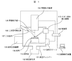
- FIG. 1 is a schematic view showing the configuration of a charged particle beam apparatus.
- Reference numeral 101 denotes a vacuum chamber, which can maintain a vacuum state by the vacuum evacuation system 102.
- a sample exchange mechanism 103 can introduce an observation sample from the outside of the apparatus while keeping the vacuum chamber 101 in a vacuum state.
- Reference numeral 104 denotes a charged particle beam source, which includes necessary cathodes such as a cathode and an anode for generating charged particle beams, a lens and an aperture for focusing generated charged particle beams, and a scanning coil for scanning charged particle beams. All systems should be included.
- the charged particle beam 105 can be focused on the sample 106 and scanned in an arbitrary order by the optical system in the charged particle beam source 104 described above.
- the secondary signal 107 generated on the surface of the sample 106 by the irradiation of the charged particle beam 105 is detected by the secondary signal detection system 108 and is input as image data to a control system 109 which also has an image calculation control function.
- the sample 106 is fixed on the sample table 110 with conductive tape, paste or the like, and can be moved in all three-dimensional directions by the sample stage 111.
- the control system 109 also controls the charged particle beam source 104, the secondary signal detection system 108, the sample stage 111, the ion liquid introduction mechanism 113, and the image display device 112.
- the signal detected by the secondary signal detection system 108 is amplified by a signal amplifier in the control system 109, transferred to an image memory, and displayed and recorded as a sample image on the image display device 112.
- An ionic liquid introduction mechanism 113 can drop the ionic liquid at any position on the sample 106.
- Reference numeral 201 denotes a liquid tank, which can store an ionic liquid 202 for dropping onto a sample.
- An injection port 203 can inject the ionic liquid 202 into the liquid tank 201.
- the inlet 203 has a lid capable of maintaining the airtightness in the liquid tank 201.
- An evacuation system 204 can evacuate the liquid tank 201.
- a shutter 205 separates the inside of the charged particle beam apparatus and the liquid tank 201, and can be closed to maintain the vacuum of the vacuum chamber 101 when the inside of the liquid tank 201 is at atmospheric pressure, and open when the inside of the liquid tank 201 is in a vacuum state.
- the ionic liquid 202 can flow out of the liquid tank 201.
- the flow rate of the ionic liquid can be adjusted by adjusting the degree of opening.
- Reference numeral 206 denotes a probe rod, which has a cavity inside, and can flow a vacuum state or an ionic liquid flowing out of the liquid tank 201 inside.
- a probe 209 is attached to the tip of the probe rod 206 via a coarse movement mechanism 207 using a mechanical structure and a fine movement mechanism 208 using a piezoelectric element, so that the sample can be approached or retracted accurately. it can.
- a cavity is present inside the coarse movement mechanism 207 and the fine movement mechanism 208 like the probe rod 206, and the ionic liquid flowing out of the liquid tank 201 and flowing in the probe rod 206 can flow to the probe 209.
- the vacuum evacuation system 204, the shutter 205, the coarse movement mechanism 207, and the fine movement mechanism 208 are controlled by the control system 109 of FIG.
- a mechanism for generating a potential difference or a current measurement is provided between the tip of the probe 209 and the grounded sample base, and the control is performed using a control system 109.
- FIG. 1 An enlarged view of the probe 209 is shown in FIG.
- the probe 209 is fixed to the probe fixing portion 301, and can be freely removed and replaced.
- a hole 302 is opened in the probe fixing portion 301, and the ionic liquid flowing out of the liquid tank 201 and flowing in the probe rod 206, the coarse movement mechanism 207, and the fine movement mechanism 208 can be transmitted to the surface of the probe 209. .
- the ionic liquid 303 transmitted to the surface of the probe 209 can be dropped onto the surface of the sample 106 from the tip of the probe 209.
- a very shallow groove may be provided from the hole 302 to the tip of the probe 209 to facilitate the transfer of the ionic liquid to the tip.
- the surface roughness of the probe 209 may be adjusted to improve the wettability with the ionic liquid.
- the probe in the charged particle beam device of this embodiment, can be brought close to the observation sample, and the ionic liquid can be dropped while observing on the sample surface. In addition, after dropping, the probe can be retracted so as not to disturb the observation.
- FIG. 4 shows secondary electron images observed before (a) and after (b) irradiation of the droplets of the ionic liquid on the Si substrate with an electron beam using a scanning electron microscope.
- the black area 401 is the droplet of the ionic liquid
- the other area 402 is the Si substrate.
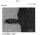
- FIG. 5 is a secondary electron image observed after the droplet of the ionic liquid is irradiated with an electron beam and the irradiated region is gradually separated from the droplet.
- the black area 501 is the ionic liquid droplet
- the other area 502 is the Si substrate.
- the region 503 irradiated with the electron beam was irradiated with the electron beam and gradually moved in the direction of the arrow. As a result, it was observed that the ionic liquid moved so as to be attracted to the electron beam irradiated region. From the above results, it was found that the ionic liquid can be induced by electron beam irradiation.
- This phenomenon is considered to be caused by the influence of potential change by electron beam irradiation or by the convection of the ionic liquid receiving the energy of the electron beam, and may occur not only to the electron beam but also to the charged particle beam in general. .
- the larger the energy or current of the electron beam the more likely the potential change or convection to occur, and the induction speed is thought to increase. However, if too much energy or current is given, the ionic liquid itself is altered and the fluidity It can be damaged.
- the energy of the electron beam is preferably about 1 to 30 kV, and the amount of current is preferably about 1 to 50 pA.
- the ionic liquid when the sample is charged by the beam irradiation and the ionic liquid is attracted by the charging, the ionic liquid is located not at the ionic liquid itself but at a distance from the ionic liquid, as long as the electric field of the charge is applied. It is also possible to guide the ionic liquid in a desired direction by irradiating the beam on the track guiding the wire (in the case of performing wiring processing, on the wiring track between the wiring processing start point and the wiring processing end point). However, if the irradiation position of the beam and the ionic liquid are separated too much, the electric field for guiding the ionic liquid may not reach the ionic liquid.
- the beam irradiation position and the ionic liquid it is desirable to set the processing conditions such that the distance between the distance and the distance is less than or equal to a predetermined value that is considered to be affected by the electric field.
- a predetermined value that is considered to be affected by the electric field.
- the irradiation areas of the beams are separated, there is a possibility of disconnection, and in view of the purpose of securing the connection of the wires, as illustrated in FIGS. It is desirable to set up an overlap.
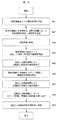
- FIG. 6 is a flow chart showing the steps of the wiring method.
- FIG. 7 is a schematic view illustrating the steps of the wiring method.
- An observation sample is inserted into the charged particle beam apparatus, and observation is started (step 601).
- the visual field is stage-moved to the target location A 701 on the sample (step 602).
- the probe 209 is brought close to the sample 106 using the coarse movement mechanism and the fine movement mechanism described in the first embodiment (step 603).
- the ionic liquid 702 is dropped to the target location A 701 using the probe 209 (step 604).
- the probe 209 is retracted from the sample 106 (step 605).
- the magnification is increased to match the desired line width (step 606).
- the field of view is adjusted so as to fall on the edge portion of the ionic liquid droplet 704, and the charged particle beam is irradiated (step 607).
- the ionic liquid spreads in the charged particle beam irradiation area, it moves to the next field of view. At this time, an overlap of about 20 to 50% with the previous field of view is provided (step 608).
- Steps 607 and 608 are repeated to induce the ionic liquid (step 609).
- the ionic liquid reaches the destination B703
- the charged particle beam irradiation is ended (step 610).
- the target points A and B are electrically wired through the ionic liquid.
- the above operation can be performed while observing, and wiring can be performed to micro areas of micro to nano level. Further, by using an electron beam as the charged particle beam 105, it is possible to reduce the sample damage which may be caused by the method of using the gas deposition by the focused ion beam.
- the charged particle beam device described in the present embodiment can automatically carry out the induction of the ionic liquid by charged particle beam irradiation in the wiring method shown in the second embodiment.
- two automatic wiring methods will be described depending on how to control the timing of movement of the visual field.
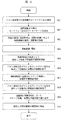
- FIG. 8 is a chart showing a process of controlling the timing of moving the visual field with time.
- the irradiation time per irradiation area is set (step 801).
- the magnification of the irradiation area is determined in accordance with the desired line width, and the number of fields of view is set according to the distance between the target points A and B (step 802).
- Automatic wiring is started (step 803).
- charged particle beam irradiation is automatically started at the set magnification (step 804).
- the charged particle beam irradiation is automatically ended according to the set irradiation time (step 805).
- the stage is automatically moved to the irradiation area B, and the charged particle beam irradiation is automatically started again (step 806).
- the charged particle beam irradiation is automatically ended according to the set irradiation time (step 807).
- the stage movement and charged particle beam irradiation are automatically repeated with the irradiation areas C, D,... (Step 808).
- the set number of fields of view is reached (step 809). From the above steps, the timing of movement of the visual field can be controlled by time to automatically perform induction of the ionic liquid by charged particle beam irradiation.
- FIG. 9 is a chart showing a process of controlling the timing of movement of the visual field by changing the contrast due to the ionic liquid spreading over the entire visual field.
- the ionic liquid portion was observed with a dark contrast compared to the Si substrate, but the contrast changes depending on the type of the ionic liquid and the Si substrate. Therefore, first, the contrast ratio of the ionic liquid to the Si substrate is measured each time (step 901). Based on the contrast ratio measured in step 901, it is set how many percent in the visual field the ionic liquid moves when the visual field is moved (step 902).
- the magnification of the irradiation area is determined in accordance with the desired line width, and the number of fields of view is set according to the distance between the target points A and B (step 903).
- Automatic wiring is started (step 904).
- charged particle beam irradiation is automatically started at the set magnification (step 905).
- the contrast change due to the spread of the ionic liquid is detected, and the charged particle beam irradiation is automatically ended according to the set percentage (step 906).
- the stage is automatically moved to the irradiation area B, and the charged particle beam irradiation is automatically started again (step 907).
- the contrast change due to the spread of the ionic liquid is detected, and the charged particle beam irradiation is automatically ended according to the set percentage (step 908).
- the stage movement and charged particle beam irradiation are repeated automatically with the irradiation areas C, D,.
- the set number of fields of view is reached (step 909). From the above steps, the timing of movement of the visual field can be controlled by the change in contrast due to the ionic liquid spreading over the entire visual field, and induction of the ionic liquid by charged particle beam irradiation can be performed automatically.
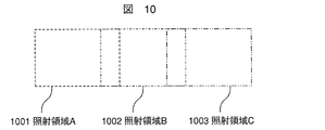
- FIG. 10 to 12 are schematic views showing the movement of the irradiation area in automatic wiring.
- FIG. 10 shows the case of moving in the lateral direction
- FIG. 11 the case of moving in the vertical direction
- FIG. 12 the case of moving in the oblique direction.
- Reference numerals 1001, 1101, and 1201 denote irradiation areas A
- reference numerals 1002, 1102, and 1202 denote irradiation areas B
- reference numerals 1003, 1103, and 1203 denote irradiation areas C.
- Irradiated areas D, E... Continue in accordance with the number of fields of view set in 802 and 903.
- an overlap of about 20 to 50% is provided.
- Wiring can be automatically performed by automating the movement of the irradiation area described above by software control. Lateral and longitudinal movements can also be automated by using the continuous image capture feature provided in the SEM.
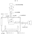
- FIG. 13 is a schematic view showing the configuration of the sample exchange mechanism 103 of FIG.
- Reference numeral 1301 denotes a sample, which is fixed to a sample table 1302.
- the sample table 1302 on which the sample 1301 is fixed is mounted on the tip of the sample exchange rod 1303, and the sample exchange rod 1303 is moved to the left and right, so that the sample can be taken in and out between the sample chamber and the sample exchange chamber.
- a sample exchange chamber 1304 is evacuated as a front stage for inserting a sample into the sample chamber.
- the tip of the sample exchange rod 1303 is a banana clip type or a two rod structure.
- the sample table 1302 is provided with a receiving portion for receiving a sample exchange rod.
- the sample exchange rod 1303 can also rotate about an axis.
- a sample rotary bar 1305 can move up and down. Further, the sample rotary rod control unit 1306 can rotate around the axis.
- FIG. 15 shows a schematic view of the mounting of the sample rotary rod tip 1501 and the sample base bottom 1502.
- the sample rotary rod tip 1501 has a cylindrical shape, and the inside is hollow and a screw groove 1503 is processed.
- the sample table bottom (rear surface) 1502 has a screw groove 1504 (receiving side) so that the tip of the sample rotary rod can be attached to the sample table bottom.
- a liquid bath 1307 plays a role of collecting the removed ionic liquid.
- An attachment 1308 is a structure for desorbing the liquid bath 1307 to the bottom of the sample exchange chamber. As shown in FIG. 16, the liquid bath bottom 1601 and the sample exchange chamber bottom 1602 are attached and fixed by the attachment 1308.
- a gate valve 1309 separates the sample exchange chamber and the sample chamber, and is opened and closed only when the sample table is taken in and out between the sample chamber and the sample exchange chamber.
- the sample exchange rod is rotated 180 degrees (reversed) to turn the sample table upside down.
- the sample rotary rod is attached to the screw type groove at the bottom of the sample table, and the sample exchange rod is removed (retracted).
- Lower the sample stage so that the sample surface is in the liquid bath using the up and down mechanism of the sample rotation bar.
- the ionic liquid is blown off by centrifugal force using the rotation mechanism of the sample rotating rod.
- the rotation mechanism may be manual or automatic drive using a motor or the like.
- the scattered ionic liquid adheres to the side wall of the liquid bath and is collected in the liquid bath. Elevate the sample table using the sample rod up and down mechanism, mount the sample exchange rod, and remove the sample rod. The sample exchange rod is rotated about the axis to flip the sample upside down. Open the valve between the sample chamber and the sample exchange chamber, insert the sample stand into the sample chamber and pull out only the sample exchange rod. The valve between the sample chamber and the sample exchange chamber is closed and the charged particle beam of the charged particle beam apparatus is irradiated and observed.
- Focused ion beams are used as a method of removing wiring locally, but since focused ion beams are also used for observation, there is a concern about sample damage during observation. In addition, when the wiring is cut with a focused ion beam, sample damage may occur.
- the charged particle beam apparatus of the present embodiment by using an electron beam as the charged particles, it is possible to reduce sample damage which may be a concern with a focused ion beam and to remove a local wiring.
- sample stage 1701 on which an ionic liquid and a sample are placed.
- the schematic diagram of a sample stand is shown in FIG.
- the material of the sample table 1701 may be made of aluminum or carbon and may have a stub-like shape, or may be another conductive material or a shape.
- the sample table 1701 is grounded via the sample stage 111 of FIG.
- the sample 1702 fixed on the sample table 1701 is not in electrical contact with the sample table, such as a pattern on a glass substrate.
- charges are accumulated on the surface of the sample, and in the case of electron microscopic observation, effects such as image drift and abnormal contrast occur.
- a hole 1703 having a diameter of about 1 to 5 mm and a depth of about 1 to 5 mm is present on the surface of the sample table 1701, and an ionic liquid 1704 is held in advance here.
- the held ionic liquid 1704 is irradiated with a charged particle beam 1705 and guided to move to a target location of the sample. From the above, the sample 1702 is grounded via the ionic liquid 1704 and the sample stage 1701, so that the influence by the above-described charging can be suppressed.
- the ionic liquid introduction mechanism is provided on the sample table 1701 described in the fifth embodiment.
- a hole 1703 having a diameter of about 1 to 5 mm and a depth of about 1 to 5 mm is present on the surface of the sample table 1701, and the ionic liquid 1704 is held in advance here.
- the probe 209 is moved and brought into contact with the ionic liquid 1704 held in the hole 1703 to attach a small amount of the ionic liquid 1801 to the probe tip. Thereafter, the probe 209 is moved to attach the ionic liquid 1801 to the target position of the sample.
- the liquid layer 201 in the ionic liquid introduction mechanism of the first embodiment is not necessary, and the ionic liquid can be introduced to the sample without adjusting the flow rate of the ionic liquid.
- the ionic liquid is induced from the grounded portion to the vicinity of the observation portion, and for example, the ionic liquid is induced to surround the observation portion, so that the charge easily escapes. It becomes possible to suppress charging and to observe.
- the ionic liquid introduction mechanism has a mechanism for generating a potential difference between the tip of the probe 209 and the grounded sample stand and measuring the current. Therefore, the tip of the probe 209 can be brought into contact with the electrode portion or the portion wired from the electrode portion, and the electron beam induced current measurement as described above can be performed. Further, by arranging a plurality of ionic liquid introducing mechanisms, it becomes possible to measure voltage-current characteristics between the respective probes, and more complicated electrical characteristics can be measured, such as a two-terminal method or a four-terminal method. By using it in combination with the wiring using an ionic liquid, flexible measurement according to the situation can be performed.
- the absorption current measurement described in the eighth embodiment can be used in combination with voltage application. Further, if a plurality of ionic liquid introduction mechanisms are installed, it is possible to apply a voltage not only between the sample stage and the probes but also between the respective probes.
- the ionic liquid is generally said to have good thermal conductivity and can be used as a thermal conductivity as well as an electrical conductivity.
- heating to about 300 ° C. and cooling to about -50 ° C. can be performed.
- the entire sample is heated and cooled.
- the ionic liquid can be used not only as an electric conduction wiring but also as a heat conduction wiring, and local heating and cooling can be performed, so that the above problems can be solved. .
- FIG. 14 is a view showing an example of a GUI (Graphical User Interface) screen for setting wiring processing conditions using an ionic liquid.
- FIG. 19 shows an input device 1910 having a display device for displaying the GUI screen shown in FIG. 14 and a signal for controlling the scanning electron microscope main body 1901 based on the wiring conditions set by the input device 1910.
- FIG. 16 is a diagram showing an example of a wiring processing system provided with a control device 1903. Between the scanning electron microscope main body 1901 and the control device 1903, an A / D converter 1902 for performing analog-to-digital conversion of signals is connected. Further, a pointing device 1911 capable of setting an arbitrary position on the GUI screen is connected to the input device 1910.
- a display area 1401 for displaying an SEM image and a processing condition input window 1407 are provided.
- the processing condition input window 1407 includes, for example, the supply amount of ionic liquid (Amount of Ionic Liquid), wiring processing start point (Starting Point), wiring processing end point (End Point), size of beam irradiation area (FOV (Field Of View) Size And electron beam beam current (Beam Current) and electron beam acceleration voltage (Acceleration Voltage) are provided to input device parameters required for wiring processing.
- Amount of Ionic Liquid the supply amount of ionic liquid
- Starting Point wiring processing start point
- End Point wiring processing end point
- size of beam irradiation area FOV (Field Of View) Size And electron beam beam current (Beam Current) and electron beam acceleration voltage (Acceleration Voltage) are provided to input device parameters required for wiring processing.
- processing conditions can be input in the display area 1401.
- Two wires 1403 and 1404 are displayed in the SEM image illustrated in FIG. 14, and the present embodiment will be described by taking a connection process between the two wires as an example.
- the dropping position of the ionic liquid and the amount of the ionic liquid are executed based on the input of "Amount of Ionic Liquid" and "Starting Point".
- the amount of ionic liquid may be dropped based on a predetermined amount stored in advance, and the dropping position may be set by the pointer 1402.
- the ionic liquid ejection control unit 1906 included in the control device 1903 illustrated in FIG. 19 can position the probe 209 and the sample stage 111 so that the ionic liquid 1405 can be ejected to the designated position.
- the ion liquid introduction mechanism 113 is controlled so that the specified amount of ion liquid can be discharged.
- the position detection unit 1907 recognizes the designated position in the display area 1401, and the coordinate conversion unit 1908 controls the stage coordinate or the ionic liquid discharge control mechanism 1906. Convert to a signal to generate a control signal.
- the optical condition setting unit 1905 sets the movement trajectory 1408 of the irradiation position so as to connect the two. It is also possible to use a pointer 1402 to set an arbitrary trajectory.
- the optical condition setting unit 1905 is a deflection signal to a deflector (not shown) for moving the beam irradiation position as time passes from the processing start point to the processing end point based on the above setting, or the sample stage 111 Generate a control signal to Wiring processing can be performed automatically by providing such irradiation area moving means.
- the memory 1909 stores in advance generation conditions of control signals based on input conditions, and generates control signals according to the generation conditions.
- the optical condition setting unit 1906 generates a scanning signal of a scanning deflector (not shown) by setting “FOV size”.
- the discharge amount of the ionic liquid may be automatically obtained by registering in advance in the memory 1909 and setting the processing start point, the processing end point, and the “FOV size”.
- a table indicating the relationship between the size of the discharge area and the discharge amount, or a relational expression is stored in advance in the memory 1909, and the discharge amount is automatically determined based on the table or the relational expression. Also good.
- the discharge amount (D1) determined by the processing start position, the processing end position, and the size of “FOV size” and the discharge amount (D2) determined by the size of the ionic liquid discharge area 2001 are “D1>
- the liquid ion required for the wiring is insufficient, so as illustrated in FIG. 20, for example, a new ion liquid discharge area 2002 is set to secure the necessary amount. good.
- the ion liquid discharge area 2002 is passed until the processing end point, so the ion liquid discharge area 2002 is a new processing start point (ion liquid supply point) It will be possible to continue processing.
- the processing can be started by pressing the Start button.
- the moving speed of the beam irradiation position may be controlled.
- scanning between the sample area displayed in the display area 1401 (wide area scanning) and scanning to the beam irradiation area 1406 (narrow area scanning) are switched continuously. You may control it. According to such control, it is possible to confirm the process of processing by a moving image. Further, as illustrated in FIG. 14, by making the setting area of the beam irradiation area 1406 visible, it becomes possible to visually compare the setting processing area with the actual processing state.
Landscapes
- Chemical & Material Sciences (AREA)
- Analytical Chemistry (AREA)
- Chemical Kinetics & Catalysis (AREA)
- Engineering & Computer Science (AREA)
- Materials Engineering (AREA)
- Mechanical Engineering (AREA)
- Metallurgy (AREA)
- Organic Chemistry (AREA)
- Analysing Materials By The Use Of Radiation (AREA)
- Sampling And Sample Adjustment (AREA)
Abstract
Description
102、204 真空排気系
103 試料交換機構
104 荷電粒子線源
105、1705 荷電粒子線
106、1301、1702 試料
107 二次信号
108 二次信号検出系
109 制御系
110、1302、1701 試料台
111 試料ステージ
112 画像表示装置
113 イオン液体導入機構
201 液槽
202、303、702、1704 イオン液体
203 注入口
205 シャッター
206 プローブロッド
207 粗動機構
208 微動機構
209 プローブ
301 プローブ固定部
302、1703 穴
401、501、704 イオン液体の液滴
402、502 Si基板
403 電子線を照射する領域
404、503 電子線照射した領域
701 目的箇所A
703 目的箇所B
1001、1101、1201 照射領域A
1002、1102、1202 照射領域B
1003、1103、1203 照射領域C
1303 試料交換棒
1304 試料交換室
1305、1505 試料回転棒
1306 試料回転棒制御部
1307 液体浴
1308 アタッチメント
1309 ゲートバルブ
1501 試料回転棒先端
1502 試料台底部
1503、1504 ネジ溝
1801 イオン液体
Claims (18)
- 試料に荷電粒子線を照射して、当該試料上に配線加工を行う配線方法において、
前記配線加工を行う配線軌道上にイオン液体を配置し、当該配線軌道に沿って前記荷電粒子線の照射位置を移動することを特徴とする配線方法。 - 請求項1において、
前記試料上に前記イオン液体を滴下し、当該滴下されたイオン液体に前記荷電粒子線を照射することを特徴とする配線方法。 - 請求項1において、
前記試料を配置するための試料台上に、前記イオン液体を配置し、当該イオン液体が配置された位置から、前記試料に向かって前記荷電粒子線の照射位置を移動することを特徴とする配線方法。 - 荷電粒子源と、
荷電粒子線が照射される試料を配置するための試料台と
当該荷電粒子源から放出される荷電粒子線の照射位置を移動する移動機構を備えた荷電粒子線装置において、
イオン液体を試料の一部に滴下するプローブと、
前記移動機構を制御する制御装置を備えたことを特徴とする荷電粒子線装置。 - 請求項4において、
前記制御装置は、前記照射位置が時間の経過に従って順次移動するように前記移動機構を制御することを特徴とする荷電粒子線装置。 - 請求項5において、
前記制御装置は、1の照射位置と、その後に照射される照射位置とが重なるように、前記照射位置を移動することを特徴とする荷電粒子線装置。 - 請求項4において、
前記移動機構は、前記荷電粒子線の照射位置を偏向する偏向器であることを特徴とする荷電粒子線装置。 - 請求項4において、
前記移動機構は、前記試料を移動するための試料ステージであることを特徴とする荷電粒子線装置。 - 荷電粒子源と、
荷電粒子線が照射される試料を配置するための試料台と
当該荷電粒子源から放出される荷電粒子線の照射位置を移動する移動機構を備えた荷電粒子線装置において、
前記試料台上に設けられるはイオン液体を保持する保持部と、
前記移動機構を制御する制御装置を備えたことを特徴とする荷電粒子線装置。 - 請求項9において、
前記制御装置は、前記照射位置が時間の経過に従って順次移動するように前記移動機構を制御することを特徴とする荷電粒子線装置。 - 請求項10において、
前記制御装置は、1の照射位置と、その後に照射される照射位置とが重なるように、前記照射位置を移動することを特徴とする荷電粒子線装置。 - 請求項9において、
前記移動機構は、前記荷電粒子線の照射位置を偏向する偏向器であることを特徴とする荷電粒子線装置。 - 請求項9において、
前記移動機構は、前記試料を移動するための試料ステージであることを特徴とする荷電粒子線装置。 - 荷電粒子源と、
荷電粒子線が照射される試料を配置するための試料台と
当該荷電粒子源から放出される荷電粒子線の照射位置を移動する移動機構を備えた荷電粒子線装置において、
前記試料台或いは前記試料上に配置されたイオン液体の移動軌道を設定する入力装置と、
当該入力装置によって設定された移動軌道に沿って、前記荷電粒子線が照射されるように、前記移動機構を制御する制御装置を備えたことを特徴とする荷電粒子線装置。 - 請求項14において、
前記制御装置は、前記移動軌道に沿って前記照射位置が時間の経過に従って順次移動するように前記移動機構を制御することを特徴とする荷電粒子線装置。 - 請求項15において、
前記制御装置は、1の照射位置と、その後に照射される照射位置とが重なるように、前記照射位置を移動することを特徴とする荷電粒子線装置。 - 請求項14において、
前記移動機構は、前記荷電粒子線の照射位置を偏向する偏向器であることを特徴とする荷電粒子線装置。 - 請求項14において、
前記移動機構は、前記試料を移動するための試料ステージであることを特徴とする荷電粒子線装置。
Priority Applications (4)
| Application Number | Priority Date | Filing Date | Title |
|---|---|---|---|
| CN201380007984.XA CN104094375B (zh) | 2012-02-06 | 2013-02-01 | 带电粒子线装置及布线方法 |
| US14/376,860 US9963776B2 (en) | 2012-02-06 | 2013-02-01 | Charged particle device and wiring method |
| DE112013000459.3T DE112013000459B4 (de) | 2012-02-06 | 2013-02-01 | Verdrahtungsverfahren |
| US15/939,689 US10808312B2 (en) | 2012-02-06 | 2018-03-29 | Charged particle device and wiring method |
Applications Claiming Priority (2)
| Application Number | Priority Date | Filing Date | Title |
|---|---|---|---|
| JP2012-022637 | 2012-02-06 | ||
| JP2012022637A JP5723801B2 (ja) | 2012-02-06 | 2012-02-06 | 荷電粒子線装置および配線方法 |
Related Child Applications (2)
| Application Number | Title | Priority Date | Filing Date |
|---|---|---|---|
| US14/376,860 A-371-Of-International US9963776B2 (en) | 2012-02-06 | 2013-02-01 | Charged particle device and wiring method |
| US15/939,689 Division US10808312B2 (en) | 2012-02-06 | 2018-03-29 | Charged particle device and wiring method |
Publications (1)
| Publication Number | Publication Date |
|---|---|
| WO2013118640A1 true WO2013118640A1 (ja) | 2013-08-15 |
Family
ID=48947404
Family Applications (1)
| Application Number | Title | Priority Date | Filing Date |
|---|---|---|---|
| PCT/JP2013/052298 WO2013118640A1 (ja) | 2012-02-06 | 2013-02-01 | 荷電粒子線装置および配線方法 |
Country Status (5)
| Country | Link |
|---|---|
| US (2) | US9963776B2 (ja) |
| JP (1) | JP5723801B2 (ja) |
| CN (1) | CN104094375B (ja) |
| DE (1) | DE112013000459B4 (ja) |
| WO (1) | WO2013118640A1 (ja) |
Cited By (1)
| Publication number | Priority date | Publication date | Assignee | Title |
|---|---|---|---|---|
| CN105388048A (zh) * | 2014-08-29 | 2016-03-09 | 日本株式会社日立高新技术科学 | 自动试样片制作装置 |
Families Citing this family (5)
| Publication number | Priority date | Publication date | Assignee | Title |
|---|---|---|---|---|
| JP2015125087A (ja) * | 2013-12-27 | 2015-07-06 | 株式会社日立ハイテクノロジーズ | 試料加工方法および試料加工装置 |
| JP6134859B2 (ja) * | 2014-03-12 | 2017-05-24 | 株式会社日立ハイテクノロジーズ | 試料観察方法及び荷電粒子線装置 |
| EP3043372B1 (en) * | 2015-01-12 | 2017-01-04 | Fei Company | Method of modifying a sample surface layer from a microscopic sample |
| CN108015496B (zh) * | 2017-12-01 | 2019-05-28 | 北京创昱科技有限公司 | 真空腔及真空腔的制备方法 |
| KR102045535B1 (ko) * | 2017-12-21 | 2019-11-15 | 울산과학기술원 | 적층 세라믹 콘덴서 표면 처리 장치 및 방법 |
Citations (4)
| Publication number | Priority date | Publication date | Assignee | Title |
|---|---|---|---|---|
| WO2007083756A1 (ja) * | 2006-01-20 | 2007-07-26 | Juridical Foundation Osaka Industrial Promotion Organization | 電子顕微鏡用チャージアップ防止液状媒体、及びそれを用いた試料観察方法 |
| JP2010133710A (ja) * | 2008-12-02 | 2010-06-17 | Hitachi High-Technologies Corp | 微小試料採取装置 |
| JP2011124162A (ja) * | 2009-12-14 | 2011-06-23 | Hitachi High-Technologies Corp | 荷電粒子線装置及び試料観察方法 |
| JP2011216426A (ja) * | 2010-04-02 | 2011-10-27 | Hitachi High-Technologies Corp | 試料ホルダーおよび試料観察方法 |
Family Cites Families (13)
| Publication number | Priority date | Publication date | Assignee | Title |
|---|---|---|---|---|
| JPH02205682A (ja) * | 1989-02-02 | 1990-08-15 | Mitsubishi Electric Corp | 荷電ビーム式加工装置 |
| GB2247345B (en) * | 1990-07-05 | 1995-04-05 | Haroon Ahmed | Integrated circuit structure analysis |
| JP3190873B2 (ja) * | 1998-03-02 | 2001-07-23 | 山形日本電気株式会社 | 収束イオンビーム装置とその制御方法 |
| JP2002110680A (ja) | 2000-10-04 | 2002-04-12 | Nec Corp | フリップチップlsiの配線修正方法 |
| US20030000921A1 (en) | 2001-06-29 | 2003-01-02 | Ted Liang | Mask repair with electron beam-induced chemical etching |
| JP2004000921A (ja) * | 2002-04-26 | 2004-01-08 | Seiko Epson Corp | 膜体形成装置、レンズの製造方法、カラーフィルタの製造方法および有機el装置の製造方法 |
| JP4754273B2 (ja) | 2005-06-06 | 2011-08-24 | 日立マクセル株式会社 | インクジェット用導電性インク、導電性パターンおよび導電体 |
| JP5226378B2 (ja) | 2008-04-28 | 2013-07-03 | 株式会社日立ハイテクノロジーズ | 透過型電子顕微鏡、及び試料観察方法 |
| JP5030906B2 (ja) * | 2008-09-11 | 2012-09-19 | 株式会社日立ハイテクノロジーズ | 走査荷電粒子顕微鏡を用いたパノラマ画像合成方法およびその装置 |
| US20110293847A1 (en) * | 2010-05-28 | 2011-12-01 | Jeffrey Todd Hastings | Particle-Beam Induced Processing Using Liquid Reactants |
| JP5707082B2 (ja) | 2010-10-08 | 2015-04-22 | 株式会社日立ハイテクノロジーズ | 液体の表面を浮遊する試料の走査電子顕微鏡観察方法 |
| JP5542749B2 (ja) | 2011-06-30 | 2014-07-09 | 株式会社日立ハイテクノロジーズ | 試料の作製装置,作製方法、及びそれを用いた荷電粒子線装置 |
| JP5951223B2 (ja) | 2011-11-02 | 2016-07-13 | 株式会社日立ハイテクノロジーズ | 電子顕微法、電子顕微鏡および観察標体作製装置 |
-
2012
- 2012-02-06 JP JP2012022637A patent/JP5723801B2/ja active Active
-
2013
- 2013-02-01 US US14/376,860 patent/US9963776B2/en not_active Expired - Fee Related
- 2013-02-01 WO PCT/JP2013/052298 patent/WO2013118640A1/ja active Application Filing
- 2013-02-01 DE DE112013000459.3T patent/DE112013000459B4/de not_active Expired - Fee Related
- 2013-02-01 CN CN201380007984.XA patent/CN104094375B/zh not_active Expired - Fee Related
-
2018
- 2018-03-29 US US15/939,689 patent/US10808312B2/en active Active
Patent Citations (4)
| Publication number | Priority date | Publication date | Assignee | Title |
|---|---|---|---|---|
| WO2007083756A1 (ja) * | 2006-01-20 | 2007-07-26 | Juridical Foundation Osaka Industrial Promotion Organization | 電子顕微鏡用チャージアップ防止液状媒体、及びそれを用いた試料観察方法 |
| JP2010133710A (ja) * | 2008-12-02 | 2010-06-17 | Hitachi High-Technologies Corp | 微小試料採取装置 |
| JP2011124162A (ja) * | 2009-12-14 | 2011-06-23 | Hitachi High-Technologies Corp | 荷電粒子線装置及び試料観察方法 |
| JP2011216426A (ja) * | 2010-04-02 | 2011-10-27 | Hitachi High-Technologies Corp | 試料ホルダーおよび試料観察方法 |
Cited By (2)
| Publication number | Priority date | Publication date | Assignee | Title |
|---|---|---|---|---|
| CN105388048A (zh) * | 2014-08-29 | 2016-03-09 | 日本株式会社日立高新技术科学 | 自动试样片制作装置 |
| CN105388048B (zh) * | 2014-08-29 | 2019-11-05 | 日本株式会社日立高新技术科学 | 自动试样片制作装置 |
Also Published As
| Publication number | Publication date |
|---|---|
| DE112013000459B4 (de) | 2018-08-02 |
| US20150299842A1 (en) | 2015-10-22 |
| US10808312B2 (en) | 2020-10-20 |
| DE112013000459T5 (de) | 2014-09-11 |
| CN104094375A (zh) | 2014-10-08 |
| US20180216223A1 (en) | 2018-08-02 |
| US9963776B2 (en) | 2018-05-08 |
| CN104094375B (zh) | 2016-08-24 |
| JP5723801B2 (ja) | 2015-05-27 |
| JP2013161647A (ja) | 2013-08-19 |
Similar Documents
| Publication | Publication Date | Title |
|---|---|---|
| US10808312B2 (en) | Charged particle device and wiring method | |
| TWI538004B (zh) | 離子顯微鏡操作方法 | |
| JP2011124162A (ja) | 荷電粒子線装置及び試料観察方法 | |
| US20220130639A1 (en) | Ablating material for an object in a particle beam device | |
| US10510508B2 (en) | Charged particle beam apparatus | |
| US20160172158A1 (en) | Sample holder and focused-ion-beam machining device provided therewith | |
| JP6727193B2 (ja) | 高電圧フィードスルー・アセンブリ、電子回折または画像化装置、および真空環境において電極装置を操作する方法 | |
| Jungjohann et al. | In situ and operando | |
| CN108666192B (zh) | 带电粒子束装置 | |
| CN106373848B (zh) | 采用等离子体中和的电子显微镜装置 | |
| JP2009037910A (ja) | 複合荷電粒子ビーム装置及び加工観察方法 | |
| TWI609402B (zh) | 一種透射型低能量電子顯微系統 | |
| JP2010197272A (ja) | 電子顕微鏡の試料コーティング方法 | |
| JP5489295B2 (ja) | 荷電粒子線装置及び荷電粒子線照射方法 | |
| JP2011243997A (ja) | 荷電粒子線装置 | |
| JP2008004569A (ja) | 帯電中和制御方法、及びそれを用いた荷電粒子線装置 | |
| JP4861675B2 (ja) | 荷電粒子線装置 | |
| US20240274397A1 (en) | Operating a particle beam apparatus | |
| US20230260744A1 (en) | Method for producing a sample on an object, computer program product, and material processing device for carrying out the method | |
| JP6134859B2 (ja) | 試料観察方法及び荷電粒子線装置 | |
| US20240038484A1 (en) | Fastening an object to a manipulator and/or to an object holder in a particle beam apparatus | |
| US20240038489A1 (en) | Method for attaching an object to a manipulator and for moving the object in a particle beam apparatus, computer program product, and particle beam apparatus | |
| US11862428B2 (en) | Processing an object using a material processing device | |
| JP5042282B2 (ja) | イオンビーム装置 | |
| JP2009266586A (ja) | 集束イオンビーム装置用の局所領域温度計測装置及び局所領域の温度計測方法 |
Legal Events
| Date | Code | Title | Description |
|---|---|---|---|
| 121 | Ep: the epo has been informed by wipo that ep was designated in this application |
Ref document number: 13746842 Country of ref document: EP Kind code of ref document: A1 |
|
| WWE | Wipo information: entry into national phase |
Ref document number: 1120130004593 Country of ref document: DE Ref document number: 112013000459 Country of ref document: DE |
|
| WWE | Wipo information: entry into national phase |
Ref document number: 14376860 Country of ref document: US |
|
| 122 | Ep: pct application non-entry in european phase |
Ref document number: 13746842 Country of ref document: EP Kind code of ref document: A1 |