WO2013111903A1 - ファンモータ - Google Patents
ファンモータ Download PDFInfo
- Publication number
- WO2013111903A1 WO2013111903A1 PCT/JP2013/051767 JP2013051767W WO2013111903A1 WO 2013111903 A1 WO2013111903 A1 WO 2013111903A1 JP 2013051767 W JP2013051767 W JP 2013051767W WO 2013111903 A1 WO2013111903 A1 WO 2013111903A1
- Authority
- WO
- WIPO (PCT)
- Prior art keywords
- stator
- rotor
- rotating shaft
- side bearing
- enclosure
- Prior art date
Links
Images

Classifications
-
- F—MECHANICAL ENGINEERING; LIGHTING; HEATING; WEAPONS; BLASTING
- F04—POSITIVE - DISPLACEMENT MACHINES FOR LIQUIDS; PUMPS FOR LIQUIDS OR ELASTIC FLUIDS
- F04D—NON-POSITIVE-DISPLACEMENT PUMPS
- F04D25/00—Pumping installations or systems
- F04D25/02—Units comprising pumps and their driving means
- F04D25/06—Units comprising pumps and their driving means the pump being electrically driven
- F04D25/0606—Units comprising pumps and their driving means the pump being electrically driven the electric motor being specially adapted for integration in the pump
-
- F—MECHANICAL ENGINEERING; LIGHTING; HEATING; WEAPONS; BLASTING
- F04—POSITIVE - DISPLACEMENT MACHINES FOR LIQUIDS; PUMPS FOR LIQUIDS OR ELASTIC FLUIDS
- F04D—NON-POSITIVE-DISPLACEMENT PUMPS
- F04D29/00—Details, component parts, or accessories
- F04D29/08—Sealings
- F04D29/083—Sealings especially adapted for elastic fluid pumps
-
- H—ELECTRICITY
- H02—GENERATION; CONVERSION OR DISTRIBUTION OF ELECTRIC POWER
- H02K—DYNAMO-ELECTRIC MACHINES
- H02K5/00—Casings; Enclosures; Supports
- H02K5/04—Casings or enclosures characterised by the shape, form or construction thereof
-
- F—MECHANICAL ENGINEERING; LIGHTING; HEATING; WEAPONS; BLASTING
- F04—POSITIVE - DISPLACEMENT MACHINES FOR LIQUIDS; PUMPS FOR LIQUIDS OR ELASTIC FLUIDS
- F04D—NON-POSITIVE-DISPLACEMENT PUMPS
- F04D25/00—Pumping installations or systems
- F04D25/02—Units comprising pumps and their driving means
- F04D25/06—Units comprising pumps and their driving means the pump being electrically driven
- F04D25/0606—Units comprising pumps and their driving means the pump being electrically driven the electric motor being specially adapted for integration in the pump
- F04D25/0613—Units comprising pumps and their driving means the pump being electrically driven the electric motor being specially adapted for integration in the pump the electric motor being of the inside-out type, i.e. the rotor is arranged radially outside a central stator
- F04D25/062—Details of the bearings
-
- F—MECHANICAL ENGINEERING; LIGHTING; HEATING; WEAPONS; BLASTING
- F04—POSITIVE - DISPLACEMENT MACHINES FOR LIQUIDS; PUMPS FOR LIQUIDS OR ELASTIC FLUIDS
- F04D—NON-POSITIVE-DISPLACEMENT PUMPS
- F04D29/00—Details, component parts, or accessories
- F04D29/05—Shafts or bearings, or assemblies thereof, specially adapted for elastic fluid pumps
- F04D29/056—Bearings
- F04D29/059—Roller bearings
-
- F—MECHANICAL ENGINEERING; LIGHTING; HEATING; WEAPONS; BLASTING
- F04—POSITIVE - DISPLACEMENT MACHINES FOR LIQUIDS; PUMPS FOR LIQUIDS OR ELASTIC FLUIDS
- F04D—NON-POSITIVE-DISPLACEMENT PUMPS
- F04D29/00—Details, component parts, or accessories
- F04D29/26—Rotors specially for elastic fluids
- F04D29/32—Rotors specially for elastic fluids for axial flow pumps
- F04D29/325—Rotors specially for elastic fluids for axial flow pumps for axial flow fans
- F04D29/329—Details of the hub
-
- H—ELECTRICITY
- H02—GENERATION; CONVERSION OR DISTRIBUTION OF ELECTRIC POWER
- H02K—DYNAMO-ELECTRIC MACHINES
- H02K1/00—Details of the magnetic circuit
- H02K1/06—Details of the magnetic circuit characterised by the shape, form or construction
- H02K1/22—Rotating parts of the magnetic circuit
- H02K1/28—Means for mounting or fastening rotating magnetic parts on to, or to, the rotor structures
- H02K1/30—Means for mounting or fastening rotating magnetic parts on to, or to, the rotor structures using intermediate parts, e.g. spiders
-
- H—ELECTRICITY
- H02—GENERATION; CONVERSION OR DISTRIBUTION OF ELECTRIC POWER
- H02K—DYNAMO-ELECTRIC MACHINES
- H02K5/00—Casings; Enclosures; Supports
- H02K5/04—Casings or enclosures characterised by the shape, form or construction thereof
- H02K5/10—Casings or enclosures characterised by the shape, form or construction thereof with arrangements for protection from ingress, e.g. water or fingers
-
- H—ELECTRICITY
- H02—GENERATION; CONVERSION OR DISTRIBUTION OF ELECTRIC POWER
- H02K—DYNAMO-ELECTRIC MACHINES
- H02K5/00—Casings; Enclosures; Supports
- H02K5/04—Casings or enclosures characterised by the shape, form or construction thereof
- H02K5/16—Means for supporting bearings, e.g. insulating supports or means for fitting bearings in the bearing-shields
- H02K5/173—Means for supporting bearings, e.g. insulating supports or means for fitting bearings in the bearing-shields using bearings with rolling contact, e.g. ball bearings
- H02K5/1732—Means for supporting bearings, e.g. insulating supports or means for fitting bearings in the bearing-shields using bearings with rolling contact, e.g. ball bearings radially supporting the rotary shaft at both ends of the rotor
-
- H—ELECTRICITY
- H02—GENERATION; CONVERSION OR DISTRIBUTION OF ELECTRIC POWER
- H02K—DYNAMO-ELECTRIC MACHINES
- H02K7/00—Arrangements for handling mechanical energy structurally associated with dynamo-electric machines, e.g. structural association with mechanical driving motors or auxiliary dynamo-electric machines
- H02K7/14—Structural association with mechanical loads, e.g. with hand-held machine tools or fans
-
- H—ELECTRICITY
- H02—GENERATION; CONVERSION OR DISTRIBUTION OF ELECTRIC POWER
- H02K—DYNAMO-ELECTRIC MACHINES
- H02K2205/00—Specific aspects not provided for in the other groups of this subclass relating to casings, enclosures, supports
- H02K2205/03—Machines characterised by thrust bearings
Definitions
- the present invention relates to a fan motor, and more particularly to a fan motor having an outer rotor structure in which a stator is disposed outside a rotor.
- a conventional fan motor employs a waterproof structure in order to prevent liquid droplets, dust and the like from entering the inside of the fan motor.
- the fan motor disclosed in Patent Document 1 includes a rotor 102 having a rotation shaft 100, a stator 104 disposed inside the rotor 102, the rotor 102 and the stator. And a surrounding body 106 that surrounds the whole 104.
- the upper end of the rotating shaft 100 passes through an insertion hole 108 formed in the enclosure 106 and protrudes to the outside of the enclosure 106, and the fan member 110 is fixed to the upper end portion.
- the enclosure 106 and the fan member 110 are provided with irregularities.
- a passage 114 between the two leading to the gap 112 is formed in a maze shape.
- an object of this invention is to provide the fan motor which can acquire reliable waterproofness and dustproof property.
- the fan motor of the present invention includes a stator, a rotor having a rotating shaft, and an enclosure surrounding the stator and the rotor in a liquid-tight manner except for the upper end of the rotating shaft. And a fan member fixed to the upper end of the rotating shaft, and the enclosure is formed with an insertion hole that passes through the upper end of the rotating shaft and protrudes out of the enclosure.
- An enclosure-side bearing is provided between the rotary shaft and the rotary shaft.
- the enclosure-side bearing is provided between the insertion hole of the enclosure and the rotation shaft, the gap between the enclosure and the rotation shaft is blocked by the enclosure-side bearing. It is. Therefore, since the enclosure can surround the rotor and the stator in a liquid-tight manner using the bearing that supports the rotating shaft, the fan motor can be reliably waterproofed and dust-proof.
- the rotor is disposed outside the stator, and a stator side bearing is provided between the stator and the rotation shaft, and the rotor includes an enclosure side bearing and a stator side bearing. It is being fixed to the rotating shaft in between.
- a so-called outer rotor structure in which the rotor is disposed outside the stator is employed, and the rotor is disposed on the rotating shaft between the enclosure-side bearing and the stator-side bearing. Since it is fixed, the rotor is supported by the double support structure by the enclosure side bearing and the stator side bearing. Therefore, the rotational motion of the rotor is stabilized, and a stable rotational operation of the fan motor can be obtained.
- FIG. 1 is a cross-sectional view of a fan motor according to an embodiment of the present invention. Sectional drawing of the conventional fan motor.
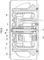
- FIG. 1 is a cross-sectional view of a fan motor according to an embodiment of the present invention.
- the fan motor 1 of the present embodiment is an AC motor, and a bracket 2 as a base part for installing the fan motor 1, a rotor 4 disposed on the bracket 2, and a fixed A child 6, a cover portion 8 surrounding the rotor 4 and the stator 6, and a fan member 10 disposed so as to cover the upper side and the periphery of the cover portion 8 are provided.
- the upper part of FIG. 1 is described as the upper part of the fan motor 1, and the lower part of FIG.
- the bracket 2 and the cover part 8 are provided, and the enclosure of this invention is comprised.
- the bracket 2 includes a bottom surface portion 12 formed in a disc shape, and a cylindrical portion 14 erected perpendicularly to the bottom surface portion 12 at the center of the bottom surface portion 12.
- An annular convex portion 16 is formed on the outer peripheral side of the bottom surface portion 12.
- the bottom of the cylindrical portion 14 is a circular opening 14A.
- the rotor 4 includes an inverted saddle-shaped rotor case 18, a core plate laminate 20 provided on the inner wall of the rotor case 18, and a rotating shaft 22.
- the rotor case 18 is formed in a bottomed cylindrical shape in which the upper surface of a cylindrical side wall is closed with a disk-shaped member, and the central portion thereof is fixed to the rotary shaft 22 via a bush 24.
- a circular recess 26 is formed around the bush 24 at the center of the disk-shaped member of the rotor case 18, and the outer peripheral wall 26 ⁇ / b>
- a of the recess 26 is cylindrical around the rotation shaft 22 and parallel to the rotation shaft 22. It extends to.
- the recessed part 26 of the rotor case 18 does not necessarily need to be formed.
- the core plate laminate 20 is formed by laminating a plurality of annular core plates made of silicon steel plates or the like, and short circuit rings (not shown) are provided on the upper and lower surfaces thereof.
- the core plate laminate 20 is disposed outside the stator 6 in parallel with the outer surface of the stator 6 and with a predetermined gap from the outer surface.
- the rotating shaft 22 is disposed in the cylindrical portion 14 at the center of the bottom surface portion 12, and a stator side bearing 28 is provided between the inner surface of the cylindrical portion 14 of the stator 6 and the outer surface of the rotating shaft 22.
- the rotating shaft 22 is rotatably supported by the stator side bearing 28 with respect to the stator 6.
- the stator side bearing 28 is fixed in the cylindrical portion 14 by a seal 14B that closes the opening 14A of the bracket 2.
- the upper end portion of the rotating shaft 22 penetrates the cover portion 8 and protrudes outside the cover portion 8.
- the stator 6 includes a core plate laminated body 30 and a coil 32 wound around the core plate laminated body 30.
- the core plate laminate 30 is formed by laminating a plurality of core plates made of silicon steel plates or the like on a bobbin case made of insulating plastic.
- the coil 32 is continuously wound around the core plate laminate 30.
- the inner periphery of the stator 6 is fixed to the outer periphery of the cylindrical portion 14 of the bracket 2.
- the inner peripheral surface of the stator 6 is located on the radially outer side with respect to the outer peripheral wall 26 ⁇ / b> A of the concave portion 26 of the rotor case 18. Therefore, for example, as shown in FIG.
- the stator 6 does not interfere with the rotor case 18 even when the bobbin case 6 ⁇ / b> A of the stator 6 protrudes above the bottom surface of the recess 26 of the rotor case 18. Therefore, the space above the recess 26 in the rotor case 18 can be used effectively.
- the cover portion 8 has an inverted bowl shape in which a cylindrical side wall 34 and an upper surface 36 covering the upper side of the side wall 34 are integrally formed. An annular recess 38 is formed on the lower end surface of the side wall 34. Yes.
- the concave portion 38 is disposed at a position corresponding to the convex portion 16 of the bracket 2, and an O-ring 40 is fitted between the concave portion 38 and the convex portion 16, whereby the lower end surface of the cover portion 8 and the bottom surface of the bracket 2.
- the part 12 is sealed.
- an insertion hole 42 through which the rotation shaft 22 is inserted is formed at the center of the upper surface 36 of the cover portion 8.
- a cover-side bearing 44 is provided between the inner surface of the insertion hole 42 and the outer surface of the rotary shaft 22.
- the cover part side bearing 44 supports the rotary shaft 22 so as to be rotatable with respect to the cover part 8 and closes a gap between the cover part 8 and the rotary shaft 22.
- a region surrounded by the cover portion 8 and the bottom surface portion 12 becomes a substantially sealed liquid-tight space 46, and a part of the rotating shaft 22, the rotor 4, and the stator are included in this space 46. 6 is housed. Therefore, the enclosure including the cover portion 8 and the bracket 2 surrounds the upper side (upper surface side), the periphery (outer peripheral side), and the lower side (lower surface side) of the rotor 4 and the stator 6.
- a coil spring 45 is inserted into the rotary shaft 22 between the inner ring of the stator side bearing 28 and the bush 24.
- the stator side bearing 28 and the bushing 24 are urged by the coil spring 45 in a direction away from each other. Accordingly, the coil spring 45 preloads and positions the inner ring of the stator side bearing 28 and the inner ring of the cover side bearing 44 through the bush 24.
- the coil spring 45 may be provided on the outer ring of the stator side bearing 28 and the cover part side bearing 44 and may be preloaded by urging the outer ring of these bearings 28 and 44.
- a bush 47 is provided between the cover side bearing 44 and the fan member 10 to ensure a distance between them.
- a frustoconical inclined surface 48 that is inclined downward toward the center is formed around the insertion hole 42 at the center of the upper surface 36 of the cover portion 8.
- a protruding annular convex portion 50 is formed, and a concave portion 52 that is recessed downward is formed on the outer peripheral side of the convex portion 50.
- a plate-like flange 54 protruding outward from the outer peripheral end of the protrusion 50 is attached to the protrusion 50, and this flange 54 covers a part of the upper portion of the recess 52.
- an annular convex portion 56 is formed at the lower end portion of the outer peripheral surface of the side wall 34 of the cover portion 8 so as to protrude outwardly from the outer peripheral surface.
- the inclined surface 48 on the upper surface of the cover portion 8 is not necessarily provided.
- the fan member 10 is disposed so as to cover the outer surface of the upper surface 36 (upper side) and the side wall 34 (surrounding) of the cover portion 8, and is a cylindrical shape integrally formed on the outer periphery of the disk-shaped upper surface 58 and the upper surface 58. It is formed in a bottomed cylindrical shape having a side wall 60, and has an inverted bowl shape as a whole. A plurality of blades 62 are formed on the outer peripheral surface of the side wall 60. A concave portion 64 that opens downward is formed at the lower edge of the fan member 10, and the convex portion 56 of the cover portion 8 projects into the concave portion 64.
- a convex portion 66 protruding downward is formed on the lower surface of the upper surface 36 of the fan member 10.
- the convex portion 66 is located outward from the flange portion 54 of the cover portion 8 and protrudes into the concave portion 52.
- a gap between the fan member 10 and the cover portion 8 is formed in a maze shape by the concave portion 64 of the fan member 10 and the convex portion 56 of the cover portion 8, and the fan member 10 and the cover portion 8 are formed from the gap. It prevents droplets and dust from entering between them.
- a recess 68 is formed at the center of the upper surface 36, and the fan member 10 is fixed to the upper end of the rotating shaft 22 in the recess 68.
- the cover part side bearing 44 is provided between the cover part 8 and the rotary shaft 22, and the rotary shaft 22 is rotatably supported by the cover part side bearing 44, the cover part 8 and the rotary shaft 22 are interposed between them.
- a gap can be prevented from being generated.
- the rotating shaft 100 is supported by bearings 118 at two locations below a bush 116 that fixes the rotor 102 to the rotating shaft 100.
- a gap 112 is generated between the enclosure 106 and the rotating shaft 100.
- the cover portion side bearing 44 that supports the rotating shaft 22 is used to fill the gap between the cover portion 8 and the rotating shaft 22.
- the rotor 6 and the stator 4 can be liquid-tightly enclosed by the enclosure constituted by the cover portion 8 and the bracket 2, and droplets, dust, and the like are generated from the gap between the cover portion 8 and the rotary shaft 22. Intrusion can be reliably prevented.
- the rotor 4 has a so-called outer rotor structure in which the rotor 4 is disposed outside the stator 6.
- the cover-side bearing 44 is disposed above the bush 24 and the stator-side bearing 28 is disposed below the bush 24. Therefore, the rotating shaft 22 can be supported on both sides of the rotor 4. Therefore, the support structure of the rotor 4 including the rotation shaft 22 is strengthened, and the rotation operation of the rotor 4 can be stabilized.
- the present invention is not limited to the above-described embodiment.
- the rotor is a so-called outer rotor structure in which the rotor is disposed outside the stator.
- a so-called inner rotor structure in which the stator is disposed outside the rotor may be employed.
- the fan motor is not limited to the AC motor as in the above-described embodiment, and a DC motor may be employed.
- a DC motor When a DC motor is employed, a magnet may be used as the rotor, and the stator is a powder magnetic core material formed by compression molding powder in addition to the one using the laminated core as described above. It is possible to adopt a structure such as a coreless type in which an air core coil is attached to a substrate without using a core. Further, as a method for insulating the stator, in addition to using a bobbin case as in the above-described embodiment, the insulating property may be ensured by applying an insulating resin to the substrate by powder baking coating.
Landscapes
- Engineering & Computer Science (AREA)
- Power Engineering (AREA)
- Mechanical Engineering (AREA)
- General Engineering & Computer Science (AREA)
- Motor Or Generator Frames (AREA)
- Connection Of Motors, Electrical Generators, Mechanical Devices, And The Like (AREA)
- Structures Of Non-Positive Displacement Pumps (AREA)
Abstract
Description
そこで、本発明は、確実な防水性、防塵性を得ることができるファンモータを提供することを目的とする。
このように構成された本発明においては、包囲体の挿通孔と回転軸との間に包囲体側軸受が設けられているので、包囲体と回転軸との間の隙間が包囲体側軸受で塞がれる。したがって、回転軸を支持する軸受を利用して包囲体が回転子及び固定子を液密に取り囲むことができるので、ファンモータの確実な防水、防塵を実現することができる。
このように構成された本発明においては、回転子が固定子の外側に配置される、所謂アウターロータ構造が採用され、回転子が、包囲体側軸受と固定子側軸受との間で回転軸に固定されているので、回転子が包囲体側軸受と固定子側軸受とによって両持ち構造で支持される。したがって、回転子の回転運動が安定し、ファンモータの安定した回転動作が得られる。
ロータケース18は、円筒状の側壁の上面を円盤状部材で塞いだ有底円筒形状に形成されており、その中央部が、ブシュ24を介して回転軸22に固定されている。ロータケース18の円盤状部材の中央部には、ブシュ24の周りに円形の凹部26が形成されており、凹部26の外周壁26Aは回転軸22の周りに円筒状に、回転軸22に平行に延びている。なお、ロータケース18の凹部26は、必ずしも形成されていなくてもよい。
コアプレート積層体20は、ケイ素鋼板等からなる環状のコアプレートを複数枚積層して形成されており、その上下面には図示しない短絡リングが設けられている。コアプレート積層体20は、固定子6の外側に、固定子6の外面と平行に且つ外面から所定の隙間を有して配置されている。
コアプレート積層体30は、絶縁性プラスチックからなるボビンケース上にケイ素鋼板等からなるコアプレートを複数枚積層して形成されている。コイル32は、コアプレート積層体30の周囲に連続的に巻き回されている。
固定子6の内周は、ブラケット2の円筒状部14の外周に固定されている。ここで、固定子6の内周面は、ロータケース18の凹部26の外周壁26Aよりも半径方向外側に位置する。従って、例えば図1に示されるように固定子6のボビンケース6Aがロータケース18の凹部26の底面よりも上方に突出している場合でも、固定子6がロータケース18に干渉することがない。したがって、ロータケース18内の、凹部26より上方のスペースを有効に利用することができる。
カバー部側軸受44とファン部材10との間には、ブッシュ47が設けられており互いの間の距離が確保されている。
このような、凸部50、鍔部54、凹部52、及び凸部66の構造により、ファン部材10とカバー部8との間の隙間は、迷路状に形成され、当該隙間に液滴や埃が侵入しにくくなっている。また、ファン部材10の凹部64とカバー部8の凸部56によっても、ファン部材10とカバー部8との間の隙間が迷路状に形成され、当該隙間からファン部材10とカバー部8との間に液滴や埃が侵入するのを防止している。また、上面36の中央部には、凹部68が形成されており、この凹部68において、ファン部材10は回転軸22の上端部に固着されている。
カバー部8と回転軸22の間にカバー部側軸受44を設けて、このカバー部側軸受44により回転軸22を回転可能に支持しているので、カバー部8と回転軸22との間に隙間が生じるのを防止することができる。図2に示した従来の構造では、回転軸100は、回転子102を回転軸100に固定するブッシュ116の下方の2箇所において軸受118に支持されている。このような従来の構造では、包囲体106と回転軸100との間に隙間112が生じる。これに対して、本実施形態では、回転子4の外側において、回転軸22を支持するカバー部側軸受44を利用してカバー部8と回転軸22との間の隙間を埋めるようにしたので、カバー部8及びブラケット2で構成された包囲体で回転子6及び固定子4を液密に包囲することができ、カバー部8と回転軸22との間の隙間から液滴や埃等が侵入するのを確実に防止することができる。
また、固定子の絶縁方法としては、前述の実施形態にようにボビンケースを用いるものの他、基体に絶縁樹脂を粉体焼付塗装することにより絶縁性を確保してもよい。
2 ブラケット
4 回転子
6 固定子
8 カバー部
10 ファン部材
22 回転軸
28 固定子側軸受
42 挿通孔
Claims (2)
- 固定子と、
回転軸を有する回転子と、
前記回転軸の上端部を除いて、前記固定子及び前記回転子の全体を液密に取り囲む包囲体と、
前記回転軸の上端部に固定されたファン部材と、を有し、
前記包囲体には、前記回転軸の上端部を挿通して前記包囲体外に突出させる挿通孔が形成されており、
前記挿通孔と前記回転軸との間には包囲体側軸受が設けられる、
ことを特徴とするファンモータ。 - 前記回転子は、前記固定子の外側に配置され、
前記固定子と前記回転軸との間には固定子側軸受が設けられ、
前記回転子は、前記包囲体側軸受と前記固定子側軸受との間において前記回転軸に固定されている、
請求項1に記載のファンモータ。
Priority Applications (4)
| Application Number | Priority Date | Filing Date | Title |
|---|---|---|---|
| US14/122,336 US20140154108A1 (en) | 2012-01-26 | 2013-01-28 | Fan motor |
| KR1020137022918A KR101493635B1 (ko) | 2012-01-26 | 2013-01-28 | 팬 모터 |
| DE112013000708.8T DE112013000708B4 (de) | 2012-01-26 | 2013-01-28 | Gebläsemotor |
| CN201380000614.3A CN103348570B (zh) | 2012-01-26 | 2013-01-28 | 风扇马达 |
Applications Claiming Priority (2)
| Application Number | Priority Date | Filing Date | Title |
|---|---|---|---|
| JP2012013943A JP5884214B2 (ja) | 2012-01-26 | 2012-01-26 | ファンモータ |
| JP2012-013943 | 2012-01-26 |
Publications (1)
| Publication Number | Publication Date |
|---|---|
| WO2013111903A1 true WO2013111903A1 (ja) | 2013-08-01 |
Family
ID=48873613
Family Applications (1)
| Application Number | Title | Priority Date | Filing Date |
|---|---|---|---|
| PCT/JP2013/051767 WO2013111903A1 (ja) | 2012-01-26 | 2013-01-28 | ファンモータ |
Country Status (7)
| Country | Link |
|---|---|
| US (1) | US20140154108A1 (ja) |
| JP (1) | JP5884214B2 (ja) |
| KR (1) | KR101493635B1 (ja) |
| CN (1) | CN103348570B (ja) |
| DE (1) | DE112013000708B4 (ja) |
| TW (1) | TWI536716B (ja) |
| WO (1) | WO2013111903A1 (ja) |
Families Citing this family (9)
| Publication number | Priority date | Publication date | Assignee | Title |
|---|---|---|---|---|
| JP6394444B2 (ja) * | 2015-03-10 | 2018-09-26 | 株式会社デンソー | ブラシレスモータ |
| TWI575849B (zh) * | 2015-05-06 | 2017-03-21 | 佛山市建準電子有限公司 | 馬達 |
| US10215231B2 (en) * | 2017-06-26 | 2019-02-26 | Asia Vital Components Co., Ltd. | Bearing structure with close fit |
| KR102371384B1 (ko) * | 2017-08-03 | 2022-03-07 | 엘지이노텍 주식회사 | 드론용 모터 |
| TWI659594B (zh) * | 2018-02-09 | 2019-05-11 | 建準電機工業股份有限公司 | 軸承定位構造及其馬達 |
| CN110932452A (zh) * | 2019-12-12 | 2020-03-27 | 浙江亿雄机电制造有限公司 | 一种高效防尘的ec电机 |
| KR102350767B1 (ko) * | 2020-06-04 | 2022-01-14 | 주식회사 오성기전 | 무브러시 직류 모터 어셈블리 |
| KR102584929B1 (ko) * | 2021-03-18 | 2023-10-05 | 주식회사 코아오토모티브 | 팬 모터 어셈블리 |
| CN117329140B (zh) * | 2023-10-17 | 2024-08-09 | 广东晟辉科技股份有限公司 | 具有防尘结构的扇叶和风扇 |
Citations (2)
| Publication number | Priority date | Publication date | Assignee | Title |
|---|---|---|---|---|
| JP2009189109A (ja) * | 2008-02-05 | 2009-08-20 | Panasonic Corp | ブラシレスモータ |
| JP4822021B2 (ja) * | 2007-12-27 | 2011-11-24 | 株式会社育良精機製作所 | ファンモータ |
Family Cites Families (11)
| Publication number | Priority date | Publication date | Assignee | Title |
|---|---|---|---|---|
| US4438361A (en) * | 1982-02-24 | 1984-03-20 | Imc Magnetics Corp. | Stepper motor having rotor with limited axial movement |
| JPH08182242A (ja) * | 1994-12-27 | 1996-07-12 | Kosoku Denki Kk | モータ用ベアリングの防塵構造 |
| US5877574A (en) * | 1997-01-30 | 1999-03-02 | General Electric Company | Dynamoelectric machine |
| IT1295466B1 (it) * | 1997-10-03 | 1999-05-12 | Bitron Spa | Motoventilatore con motore elettrico ermeticamente sigillato. |
| US7012346B2 (en) | 2003-03-07 | 2006-03-14 | Resmed Limited | Low profile d.c. brushless motor for an impeller mechanism or the like |
| CA2531634A1 (en) * | 2003-07-10 | 2005-01-27 | Magnetic Applications Inc. | Compact high power alternator |
| DE502005005690D1 (de) * | 2004-03-16 | 2008-11-27 | Emb Papst St Georgen Gmbh & Co | Anordnung mit einem elektronisch kommutierten aussenläufermotor |
| JP2006150571A (ja) | 2004-12-01 | 2006-06-15 | Nidec Shibaura Corp | 電動工具 |
| JP2010098816A (ja) | 2008-10-15 | 2010-04-30 | Shinano Kenshi Co Ltd | ブロアモータ |
| GB2467966B (en) * | 2009-02-24 | 2013-04-03 | Dyson Technology Ltd | Rotor assembly |
| JP4882021B1 (ja) | 2010-12-24 | 2012-02-22 | 春彦 極檀 | 熱交換システム |
-
2012
- 2012-01-26 JP JP2012013943A patent/JP5884214B2/ja active Active
-
2013
- 2013-01-24 TW TW102102591A patent/TWI536716B/zh active
- 2013-01-28 DE DE112013000708.8T patent/DE112013000708B4/de active Active
- 2013-01-28 WO PCT/JP2013/051767 patent/WO2013111903A1/ja active Application Filing
- 2013-01-28 KR KR1020137022918A patent/KR101493635B1/ko active IP Right Grant
- 2013-01-28 US US14/122,336 patent/US20140154108A1/en not_active Abandoned
- 2013-01-28 CN CN201380000614.3A patent/CN103348570B/zh active Active
Patent Citations (2)
| Publication number | Priority date | Publication date | Assignee | Title |
|---|---|---|---|---|
| JP4822021B2 (ja) * | 2007-12-27 | 2011-11-24 | 株式会社育良精機製作所 | ファンモータ |
| JP2009189109A (ja) * | 2008-02-05 | 2009-08-20 | Panasonic Corp | ブラシレスモータ |
Also Published As
| Publication number | Publication date |
|---|---|
| CN103348570A (zh) | 2013-10-09 |
| JP2013153628A (ja) | 2013-08-08 |
| CN103348570B (zh) | 2016-05-04 |
| TW201340555A (zh) | 2013-10-01 |
| DE112013000708B4 (de) | 2022-08-18 |
| TWI536716B (zh) | 2016-06-01 |
| KR20130111642A (ko) | 2013-10-10 |
| JP5884214B2 (ja) | 2016-03-15 |
| DE112013000708T5 (de) | 2014-11-20 |
| US20140154108A1 (en) | 2014-06-05 |
| KR101493635B1 (ko) | 2015-02-13 |
Similar Documents
| Publication | Publication Date | Title |
|---|---|---|
| JP5884214B2 (ja) | ファンモータ | |
| JP2019112998A (ja) | 送風機 | |
| JP2016008579A (ja) | 軸流送風機 | |
| JP6878986B2 (ja) | ステータユニット、モータ、及びファンモータ | |
| JP2017225337A (ja) | モータ | |
| JP2016165198A (ja) | 回転機の防水構造及び回転機 | |
| KR20140067890A (ko) | 배수 펌프용 모터 | |
| JP2012186956A (ja) | ブラシレスモータ及び送風ファン | |
| JP5402829B2 (ja) | 防水モータ | |
| EP3364527B1 (en) | Electric motor and blower | |
| JP5752628B2 (ja) | 回転電機およびシール機構 | |
| JP2017034740A (ja) | ブラシレスモータ | |
| JP2018157716A (ja) | 電動機及び軸受ブラケット | |
| KR101800260B1 (ko) | 팬모터 조립체 | |
| CN108933493B (zh) | 马达及风扇马达 | |
| JP2018198521A (ja) | ステータユニット、モータ、及びファンモータ | |
| KR102335904B1 (ko) | 모터 | |
| JP2015142437A (ja) | 電動機 | |
| JP2011035950A (ja) | 電動機の防水構造 | |
| JP2020133550A (ja) | 軸流ファン | |
| JP2020054174A (ja) | ステータユニット、モータ、及び送風装置 | |
| JP2018198503A (ja) | モータ | |
| JP2019022325A (ja) | モータ | |
| TWI422126B (zh) | 散熱風扇 | |
| JP2015050817A (ja) | ブラシレスモータ、ブラシレスモータ装置、及び、ブラシレスモータ装置の設置方法 |
Legal Events
| Date | Code | Title | Description |
|---|---|---|---|
| WWE | Wipo information: entry into national phase |
Ref document number: 201380000614.3 Country of ref document: CN |
|
| ENP | Entry into the national phase |
Ref document number: 20137022918 Country of ref document: KR Kind code of ref document: A |
|
| 121 | Ep: the epo has been informed by wipo that ep was designated in this application |
Ref document number: 13740501 Country of ref document: EP Kind code of ref document: A1 |
|
| WWE | Wipo information: entry into national phase |
Ref document number: 14122336 Country of ref document: US |
|
| WWE | Wipo information: entry into national phase |
Ref document number: 1120130007088 Country of ref document: DE Ref document number: 112013000708 Country of ref document: DE |
|
| 122 | Ep: pct application non-entry in european phase |
Ref document number: 13740501 Country of ref document: EP Kind code of ref document: A1 |