WO2013108286A1 - 排気加熱装置の燃焼率算出方法 - Google Patents
排気加熱装置の燃焼率算出方法 Download PDFInfo
- Publication number
- WO2013108286A1 WO2013108286A1 PCT/JP2012/000222 JP2012000222W WO2013108286A1 WO 2013108286 A1 WO2013108286 A1 WO 2013108286A1 JP 2012000222 W JP2012000222 W JP 2012000222W WO 2013108286 A1 WO2013108286 A1 WO 2013108286A1
- Authority
- WO
- WIPO (PCT)
- Prior art keywords
- exhaust
- exhaust gas
- fuel
- temperature
- rate
- Prior art date
- Legal status (The legal status is an assumption and is not a legal conclusion. Google has not performed a legal analysis and makes no representation as to the accuracy of the status listed.)
- Ceased
Links
Images



Classifications
-
- G—PHYSICS
- G01—MEASURING; TESTING
- G01M—TESTING STATIC OR DYNAMIC BALANCE OF MACHINES OR STRUCTURES; TESTING OF STRUCTURES OR APPARATUS, NOT OTHERWISE PROVIDED FOR
- G01M15/00—Testing of engines
- G01M15/04—Testing internal-combustion engines
- G01M15/10—Testing internal-combustion engines by monitoring exhaust gases or combustion flame
- G01M15/102—Testing internal-combustion engines by monitoring exhaust gases or combustion flame by monitoring exhaust gases
-
- F—MECHANICAL ENGINEERING; LIGHTING; HEATING; WEAPONS; BLASTING
- F01—MACHINES OR ENGINES IN GENERAL; ENGINE PLANTS IN GENERAL; STEAM ENGINES
- F01N—GAS-FLOW SILENCERS OR EXHAUST APPARATUS FOR MACHINES OR ENGINES IN GENERAL; GAS-FLOW SILENCERS OR EXHAUST APPARATUS FOR INTERNAL-COMBUSTION ENGINES
- F01N3/00—Exhaust or silencing apparatus having means for purifying, rendering innocuous, or otherwise treating exhaust
- F01N3/08—Exhaust or silencing apparatus having means for purifying, rendering innocuous, or otherwise treating exhaust for rendering innocuous
- F01N3/10—Exhaust or silencing apparatus having means for purifying, rendering innocuous, or otherwise treating exhaust for rendering innocuous by thermal or catalytic conversion of noxious components of exhaust
- F01N3/24—Exhaust or silencing apparatus having means for purifying, rendering innocuous, or otherwise treating exhaust for rendering innocuous by thermal or catalytic conversion of noxious components of exhaust characterised by constructional aspects of converting apparatus
- F01N3/36—Arrangements for supply of additional fuel
-
- F—MECHANICAL ENGINEERING; LIGHTING; HEATING; WEAPONS; BLASTING
- F01—MACHINES OR ENGINES IN GENERAL; ENGINE PLANTS IN GENERAL; STEAM ENGINES
- F01N—GAS-FLOW SILENCERS OR EXHAUST APPARATUS FOR MACHINES OR ENGINES IN GENERAL; GAS-FLOW SILENCERS OR EXHAUST APPARATUS FOR INTERNAL-COMBUSTION ENGINES
- F01N3/00—Exhaust or silencing apparatus having means for purifying, rendering innocuous, or otherwise treating exhaust
- F01N3/02—Exhaust or silencing apparatus having means for purifying, rendering innocuous, or otherwise treating exhaust for cooling, or for removing solid constituents of, exhaust
- F01N3/021—Exhaust or silencing apparatus having means for purifying, rendering innocuous, or otherwise treating exhaust for cooling, or for removing solid constituents of, exhaust by means of filters
- F01N3/023—Exhaust or silencing apparatus having means for purifying, rendering innocuous, or otherwise treating exhaust for cooling, or for removing solid constituents of, exhaust by means of filters using means for regenerating the filters, e.g. by burning trapped particles
- F01N3/025—Exhaust or silencing apparatus having means for purifying, rendering innocuous, or otherwise treating exhaust for cooling, or for removing solid constituents of, exhaust by means of filters using means for regenerating the filters, e.g. by burning trapped particles using fuel burner or by adding fuel to exhaust
-
- F—MECHANICAL ENGINEERING; LIGHTING; HEATING; WEAPONS; BLASTING
- F01—MACHINES OR ENGINES IN GENERAL; ENGINE PLANTS IN GENERAL; STEAM ENGINES
- F01N—GAS-FLOW SILENCERS OR EXHAUST APPARATUS FOR MACHINES OR ENGINES IN GENERAL; GAS-FLOW SILENCERS OR EXHAUST APPARATUS FOR INTERNAL-COMBUSTION ENGINES
- F01N3/00—Exhaust or silencing apparatus having means for purifying, rendering innocuous, or otherwise treating exhaust
- F01N3/08—Exhaust or silencing apparatus having means for purifying, rendering innocuous, or otherwise treating exhaust for rendering innocuous
- F01N3/10—Exhaust or silencing apparatus having means for purifying, rendering innocuous, or otherwise treating exhaust for rendering innocuous by thermal or catalytic conversion of noxious components of exhaust
- F01N3/18—Exhaust or silencing apparatus having means for purifying, rendering innocuous, or otherwise treating exhaust for rendering innocuous by thermal or catalytic conversion of noxious components of exhaust characterised by methods of operation; Control
- F01N3/20—Exhaust or silencing apparatus having means for purifying, rendering innocuous, or otherwise treating exhaust for rendering innocuous by thermal or catalytic conversion of noxious components of exhaust characterised by methods of operation; Control specially adapted for catalytic conversion
- F01N3/2006—Periodically heating or cooling catalytic reactors, e.g. at cold starting or overheating
- F01N3/2033—Periodically heating or cooling catalytic reactors, e.g. at cold starting or overheating using a fuel burner or introducing fuel into exhaust duct
-
- F—MECHANICAL ENGINEERING; LIGHTING; HEATING; WEAPONS; BLASTING
- F01—MACHINES OR ENGINES IN GENERAL; ENGINE PLANTS IN GENERAL; STEAM ENGINES
- F01N—GAS-FLOW SILENCERS OR EXHAUST APPARATUS FOR MACHINES OR ENGINES IN GENERAL; GAS-FLOW SILENCERS OR EXHAUST APPARATUS FOR INTERNAL-COMBUSTION ENGINES
- F01N9/00—Electrical control of exhaust gas treating apparatus
-
- F—MECHANICAL ENGINEERING; LIGHTING; HEATING; WEAPONS; BLASTING
- F02—COMBUSTION ENGINES; HOT-GAS OR COMBUSTION-PRODUCT ENGINE PLANTS
- F02D—CONTROLLING COMBUSTION ENGINES
- F02D41/00—Electrical control of supply of combustible mixture or its constituents
- F02D41/02—Circuit arrangements for generating control signals
- F02D41/14—Introducing closed-loop corrections
- F02D41/1438—Introducing closed-loop corrections using means for determining characteristics of the combustion gases; Sensors therefor
- F02D41/1444—Introducing closed-loop corrections using means for determining characteristics of the combustion gases; Sensors therefor characterised by the characteristics of the combustion gases
- F02D41/1454—Introducing closed-loop corrections using means for determining characteristics of the combustion gases; Sensors therefor characterised by the characteristics of the combustion gases the characteristics being an oxygen content or concentration or the air-fuel ratio
- F02D41/1458—Introducing closed-loop corrections using means for determining characteristics of the combustion gases; Sensors therefor characterised by the characteristics of the combustion gases the characteristics being an oxygen content or concentration or the air-fuel ratio with determination means using an estimation
-
- G—PHYSICS
- G01—MEASURING; TESTING
- G01M—TESTING STATIC OR DYNAMIC BALANCE OF MACHINES OR STRUCTURES; TESTING OF STRUCTURES OR APPARATUS, NOT OTHERWISE PROVIDED FOR
- G01M15/00—Testing of engines
- G01M15/04—Testing internal-combustion engines
- G01M15/042—Testing internal-combustion engines by monitoring a single specific parameter not covered by groups G01M15/06 - G01M15/12
-
- G—PHYSICS
- G01—MEASURING; TESTING
- G01M—TESTING STATIC OR DYNAMIC BALANCE OF MACHINES OR STRUCTURES; TESTING OF STRUCTURES OR APPARATUS, NOT OTHERWISE PROVIDED FOR
- G01M15/00—Testing of engines
- G01M15/04—Testing internal-combustion engines
- G01M15/042—Testing internal-combustion engines by monitoring a single specific parameter not covered by groups G01M15/06 - G01M15/12
- G01M15/048—Testing internal-combustion engines by monitoring a single specific parameter not covered by groups G01M15/06 - G01M15/12 by monitoring temperature
-
- F—MECHANICAL ENGINEERING; LIGHTING; HEATING; WEAPONS; BLASTING
- F01—MACHINES OR ENGINES IN GENERAL; ENGINE PLANTS IN GENERAL; STEAM ENGINES
- F01N—GAS-FLOW SILENCERS OR EXHAUST APPARATUS FOR MACHINES OR ENGINES IN GENERAL; GAS-FLOW SILENCERS OR EXHAUST APPARATUS FOR INTERNAL-COMBUSTION ENGINES
- F01N2560/00—Exhaust systems with means for detecting or measuring exhaust gas components or characteristics
- F01N2560/06—Exhaust systems with means for detecting or measuring exhaust gas components or characteristics the means being a temperature sensor
-
- F—MECHANICAL ENGINEERING; LIGHTING; HEATING; WEAPONS; BLASTING
- F01—MACHINES OR ENGINES IN GENERAL; ENGINE PLANTS IN GENERAL; STEAM ENGINES
- F01N—GAS-FLOW SILENCERS OR EXHAUST APPARATUS FOR MACHINES OR ENGINES IN GENERAL; GAS-FLOW SILENCERS OR EXHAUST APPARATUS FOR INTERNAL-COMBUSTION ENGINES
- F01N2900/00—Details of electrical control or of the monitoring of the exhaust gas treating apparatus
- F01N2900/06—Parameters used for exhaust control or diagnosing
- F01N2900/14—Parameters used for exhaust control or diagnosing said parameters being related to the exhaust gas
- F01N2900/1404—Exhaust gas temperature
-
- Y—GENERAL TAGGING OF NEW TECHNOLOGICAL DEVELOPMENTS; GENERAL TAGGING OF CROSS-SECTIONAL TECHNOLOGIES SPANNING OVER SEVERAL SECTIONS OF THE IPC; TECHNICAL SUBJECTS COVERED BY FORMER USPC CROSS-REFERENCE ART COLLECTIONS [XRACs] AND DIGESTS
- Y02—TECHNOLOGIES OR APPLICATIONS FOR MITIGATION OR ADAPTATION AGAINST CLIMATE CHANGE
- Y02T—CLIMATE CHANGE MITIGATION TECHNOLOGIES RELATED TO TRANSPORTATION
- Y02T10/00—Road transport of goods or passengers
- Y02T10/10—Internal combustion engine [ICE] based vehicles
- Y02T10/12—Improving ICE efficiencies
-
- Y—GENERAL TAGGING OF NEW TECHNOLOGICAL DEVELOPMENTS; GENERAL TAGGING OF CROSS-SECTIONAL TECHNOLOGIES SPANNING OVER SEVERAL SECTIONS OF THE IPC; TECHNICAL SUBJECTS COVERED BY FORMER USPC CROSS-REFERENCE ART COLLECTIONS [XRACs] AND DIGESTS
- Y02—TECHNOLOGIES OR APPLICATIONS FOR MITIGATION OR ADAPTATION AGAINST CLIMATE CHANGE
- Y02T—CLIMATE CHANGE MITIGATION TECHNOLOGIES RELATED TO TRANSPORTATION
- Y02T10/00—Road transport of goods or passengers
- Y02T10/10—Internal combustion engine [ICE] based vehicles
- Y02T10/40—Engine management systems
Definitions
- the present invention relates to a method for calculating the combustion rate of fuel added to an exhaust passage when the exhaust is heated using an exhaust heating device disposed in the exhaust passage of the internal combustion engine.
- Patent Document 1 and the like propose an internal combustion engine in which an exhaust heating device is incorporated in an exhaust passage upstream of the exhaust purification device.
- the exhaust gas heating device generates a heating gas in the exhaust gas, and supplies the generated heating gas to the exhaust gas purification device on the downstream side, thereby promoting activation of the exhaust gas purification device or maintaining an active state.
- the exhaust heating device generally includes a fuel addition valve that adds fuel to the exhaust passage, and an ignition device such as a glow plug that generates heated gas by heating and igniting the fuel.
- An intake air heating device used in an internal combustion engine or the like disclosed in Patent Document 2 or Patent Document 3 detects an ignition temperature of fuel added to a combustor, and determines that a misfire occurs when the detected temperature is lower than a predetermined value. Thus, fuel addition to the combustor is stopped.
- Cited Document 2 when detecting the intake air temperature when the fuel is ignited, the ignition / misfire determination is performed at the temperature convergence stage after the combustion is completed. In such a case, an unburned fuel in an amount corresponding to the misfire period may be supplied to the engine side. For this reason, when the technique of the cited reference 2 is diverted to the exhaust gas heating device, the exhaust gas purification device may be adversely affected.
- Cited Document 3 a misfire sign is determined based on a temperature change when the fuel added to the intake passage is ignited.
- the ignition / misfire determination cannot be performed until the temperature change is stabilized, and the same problem as in the cited document 2 is caused.
- An object of the present invention is to provide a method capable of estimating in real time the combustion rate of fuel added to an exhaust passage by an exhaust heating device with high reliability.
- the combustion rate is the ratio of the actual amount of fuel burned with respect to the amount of fuel supplied, that is, the amount of fuel added. For example, a combustion rate of 0% means that the added fuel did not burn at all. Conversely, a combustion rate of 100% indicates that all the fuel has been burned.
- the combustion rate calculation method adds fuel to the exhaust passage of the internal combustion engine, and heats the fuel added to the exhaust passage to ignite it, thereby heating the exhaust discharged from the internal combustion engine.
- a method for calculating the combustion rate of the added to the exhaust passage fuel acquires the temperature T O of the exhaust gas fuel added to the exhaust passage flows through the downstream side of the exhaust passage than the area of burning in the exhaust temperature sensor A step of obtaining the heat capacity CE of the exhaust, a step of obtaining the energy amount Q F of the fuel supplied to the exhaust passage, and an increase amount ⁇ T O of the exhaust temperature T O immediately before heating the exhaust.
- an exhaust purification device is incorporated in the middle of the exhaust passage, fuel is added to the exhaust passage upstream of the exhaust purification device, and the exhaust temperature sensor is upstream of the exhaust purification device. it may be used for detecting the exhaust gas temperature T O flowing through the exhaust passage.
- the parameter Z includes at least one of the thermal conductivity ⁇ S of the exhaust temperature sensor itself, the thermal capacity C S of the exhaust temperature sensor, and the thermal conductivity ⁇ E transmitted from the exhaust flowing through the exhaust passage to the exhaust temperature sensor, z 1 ,
- Z z 1 ⁇ C S
- Z z 2 ⁇ C S ⁇ 1 / (z 3 ⁇ ⁇ S ) ⁇
- Z z 4 ⁇ C S ⁇ 1 / (z 5 ⁇ ⁇ E ) ⁇
- Z C S [ ⁇ 1 / (z 3 ⁇ ⁇ S ) ⁇ + ⁇ 1 / (z 5 ⁇ ⁇ E ) ⁇ ].
- the method may further include a step of correcting the exhaust gas temperature T O based on at least one of the flow rate v E of the exhaust gas flowing through the exhaust passage and the exhaust gas temperature T O.
- the method may further include a step of correcting the exhaust gas temperature T I based on at least one of the flow rate
- Change rate dT O of exhaust gas temperature T O of the predetermined time after the start of the addition of fuel to the exhaust passage t further comprises the step of determining whether a threshold value or more set in advance, the fuel to the exhaust passage If added from the start of the change rate dT O of exhaust gas temperature T O after the predetermined time t is less than the threshold value of the combustion rate of the fuel can be calculated as 0.
- the predetermined time t may comprise a flow time of the exhaust leading from the addition region of the fuel in the detection area of the exhaust gas temperature T O in the exhaust passage.
- the method may further include a step of correcting the predetermined time t based on the exhaust gas temperature T O detected by the exhaust gas temperature sensor.
- the difference between these change rates dT O and the rate of change dT I may be one which ends when less than the predetermined value.
- the step of calculating the combustion rate RC of the fuel can be completed at the time when the time required for adding the fuel to the exhaust passage has passed from immediately before heating the exhaust.
- the parameter Z is z 1 ⁇ C S , z 2 ⁇ C S ⁇ 1 / (z 3 ⁇ ⁇ S ) ⁇ , z 4 ⁇ C S ⁇ 1 / (z 5 ⁇ ⁇ E ) ⁇ , or C S [ ⁇ When 1 / (z 3 ⁇ ⁇ S ) ⁇ + ⁇ 1 / (z 5 ⁇ ⁇ E ) ⁇ ], the combustion rate of the fuel added to the exhaust passage can be grasped with higher reliability.
- the method further includes a step of correcting the exhaust temperature T O based on at least one of the flow rate v E of the exhaust gas flowing through the exhaust passage and the exhaust temperature T O , the combustion rate can be grasped with higher accuracy.
- the influence due to the change in the exhaust gas temperature flowing into the exhaust gas heating device can be taken into account.
- the flow rate v E and exhaust gas temperature T O of the exhaust gas flowing in the exhaust passage when further comprising the step of correcting the exhaust gas temperature T I, even higher combustion rate were added to the exhaust passage fuel It is possible to grasp the accuracy.
- the change rate dT O of exhaust gas temperature T O of the predetermined time after the start of the addition of fuel to the exhaust passage t is less than the threshold value, by calculating the combustion rate of the fuel 0, it is added to the exhaust passage It is possible to prevent a problem that the fuel remains unburned.
- the predetermined time t reaches the detection area of the exhaust temperature T O from the addition region of the fuel in the exhaust passage, when coupling, in particular a predetermined time t was A E / q, from the exhaust heating device It is possible to determine the combustion rate of 0 at an appropriate timing according to the distance to the exhaust temperature sensor.
- FIG. 1 is a conceptual diagram of an embodiment in which a combustion rate calculation method according to the present invention is applied to a compression ignition type multi-cylinder internal combustion engine.
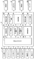
- FIG. 2 is a control block diagram of the main part of the embodiment shown in FIG.
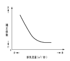
- FIG. 3 is a map schematically showing the relationship between the exhaust flow rate and the correction coefficient for the second exhaust temperature.
- FIG. 4 is a map schematically showing the relationship between the exhaust temperature and the correction coefficient for the second exhaust temperature.
- FIG. 5 is a flowchart showing the procedure of the exhaust gas heating process in the embodiment shown in FIG.
- FIG. 6 is a graph schematically showing changes in the second exhaust temperature and the combustion rate in the embodiment shown in FIG.
- the present invention is not limited to such an embodiment, and the configuration can be freely changed according to required characteristics.
- the present invention is also effective for a spark ignition type internal combustion engine in which gasoline, alcohol, LNG (liquefied natural gas) or the like is used as fuel and is ignited by a spark plug.
- FIG. 1 The main part of the engine system in the present embodiment is schematically shown in FIG. 1, and the control block of the main part is schematically shown in FIG.
- a general exhaust turbo supercharger, an EGR device, and the like are omitted as auxiliary equipment of the engine 10. It should be noted that some of the various sensors required for smooth operation of the engine 10 are omitted for convenience.
- the engine 10 in this embodiment is a compression ignition type multi-cylinder internal combustion engine that spontaneously ignites by directly injecting light oil as fuel into the combustion chamber 10a in a compressed state from the fuel injection valve 11.
- a single cylinder internal combustion engine may be used due to the characteristics of the present invention.
- the cylinder head 12 formed with the intake port 12a and the exhaust port 12b facing the combustion chamber 10a has a valve operating mechanism (not shown) including an intake valve 13a for opening and closing the intake port 12a and an exhaust valve 13b for opening and closing the exhaust port 12b. It has been incorporated.
- the previous fuel injection valve 11 facing the center of the upper end of the combustion chamber 10a is also assembled to the cylinder head 12 so as to be sandwiched between the intake valve 13a and the exhaust valve 13b.
- the amount and injection timing of fuel supplied to the combustion chamber 10a from the fuel injection valve 11, the ECU (E lectronic C ontrol U nit ) 15 based on operating conditions of the vehicle including the depression amount of the accelerator pedal 14 by the driver Be controlled.
- the amount of depression of the accelerator pedal 14 is detected by the accelerator opening sensor 16, and the detection information is output to the ECU 15.
- the ECU 15 is based on information from the accelerator opening sensor 16 and various sensors to be described later, an operation state determination unit 15a for determining the operation state of the vehicle, a fuel injection setting unit 15b, and a fuel injection valve drive unit 15c.
- the fuel injection setting unit 15b sets the fuel injection amount and the injection timing from the fuel injection valve 11 based on the determination result in the operation state determination unit 15a.
- the fuel injection valve drive unit 15c controls the operation of the fuel injection valve 11 so that the amount of fuel set by the fuel injection setting unit 15b is injected from the fuel injection valve 11 at the set time.
- a surge tank 18 is formed in the middle of the intake pipe 17 connected to the cylinder head 12 so as to communicate with the intake port 12a and defining the intake passage 17a together with the intake port 12a.
- a throttle valve 20 for adjusting the opening degree of the intake passage 17 a is incorporated in the intake pipe 17 upstream of the surge tank 18 via a throttle actuator 19.
- An air flow meter 21 that detects the flow rate of the intake air flowing through the intake passage 17a and outputs it to the ECU 15 is attached to the intake pipe 17 upstream of the throttle valve 20.
- an exhaust flow sensor having the same configuration may be attached to a portion of the exhaust pipe 23 located between an exhaust heating device 22 described later and the exhaust port 12b of the cylinder head 12.
- the previous ECU 15 further includes a throttle opening setting unit 15d and an actuator driving unit 15e.
- the throttle opening setting unit 15d sets the opening of the throttle valve 20 based on the determination result of the previous operation state determination unit 15a in addition to the depression amount of the accelerator pedal 14.
- the actuator driving unit 15e controls the operation of the throttle actuator 19 so that the throttle valve 20 has the opening set by the throttle opening setting unit 15d.
- a crank angle sensor 25 that detects the rotational phase of the crankshaft 24c to which the piston 24a is connected via the connecting rod 24b, that is, the crank angle, and outputs it to the ECU 15 is attached to the cylinder block 24 in which the piston 24a reciprocates. It has been. Based on the information from the crank angle sensor 25, the driving state determination unit 15a of the ECU 15 grasps the traveling speed of the vehicle in addition to the rotational phase of the crankshaft 24c and the engine speed in real time.
- the exhaust pipe 23 connected to the cylinder head 12 so as to communicate with the exhaust port 12b defines an exhaust passage 23a together with the exhaust port 12b.
- An exhaust purification device 26 for detoxifying harmful substances generated by combustion of the air-fuel mixture in the combustion chamber 10a is provided in the middle of the exhaust pipe 23 upstream of the silencer (not shown) attached to the downstream end side. It is attached.
- Exhaust purification apparatus 26 of this embodiment includes at least an oxidation catalyst, it is also possible to incorporate the like In addition to this DPF (D iesel P articulate F ilter ) and the NO X storage catalyst.
- the oxidation catalyst is mainly for oxidizing unburned gas contained in the exhaust gas, that is, for burning.
- a catalyst temperature sensor 27 for detecting the temperature of the exhaust gas from the oxidation catalyst (hereinafter referred to as catalyst temperature) and outputting the detected temperature to the ECU 15 is incorporated. Yes. Based on the information from the catalyst temperature sensor 27, the operation state determination unit 15a of the ECU 15 also grasps whether or not the oxidation catalyst is in an active state.
- Exhaust heating device 22 is arranged in the middle of the exhaust pipe 23 upstream of the exhaust purification device 26, so that its activation and active state are maintained.
- Exhaust heating device 22 is arranged.
- the exhaust heating device 22 in the present embodiment includes a fuel addition valve 22a and a glow plug 22b.
- the fuel addition valve 22a has the same basic configuration as that of the normal fuel injection valve 11, and supplies an arbitrary amount of fuel to the exhaust passage 23a at an arbitrary time interval by controlling the energization time. Can be done.
- the amount of fuel per time supplied from the fuel addition valve 22a to the exhaust passage 23a is based on the operating state of the vehicle including the intake air amount and air-fuel ratio detected by the air flow meter 21, and the fuel addition setting unit of the ECU 15 It is set by 15f.
- the fuel addition setting unit 15f also combines the energy amount of the fuel to be supplied, that is, the fuel addition amount Q F based on the difference between the target catalyst temperature and the current catalyst temperature detected by the catalyst temperature sensor 27. calculate.
- the lowest catalyst activity temperature As the catalyst temperature to be targeted, the lowest temperature at which the oxidation catalyst becomes active (hereinafter referred to as the lowest catalyst activity temperature) is generally selected.
- an air-fuel ratio sensor may be incorporated in the exhaust passage 23a and read from a detection signal from the air-fuel ratio sensor.
- the fuel addition valve drive unit 15g of the ECU 15 controls the operation of the fuel addition valve 22a so that the amount of fuel set by the fuel addition setting unit 15f is injected from the fuel addition valve 22a at a set cycle. In this case, operation of the fuel addition valve 22a until the fuel addition amount accumulated from the start of the fuel addition reaches a fuel addition amount Q F set by the fuel addition setting unit 15f, it is basically carried out.
- the glow plug 22b for igniting the fuel added from the fuel addition valve 22a to the exhaust passage 23a is connected to a vehicle power supply (not shown) via a glow plug drive unit 15h of the ECU 15 as an on / off switch. Accordingly, switching between energization and non-energization for the glow plug 22b is controlled by the glow plug drive unit 15h of the ECU 15 according to a preset program.
- the fuel addition valve 22a when the engine 10 is in a motoring state, that is, when the opening of the accelerator pedal 14 becomes 0 during operation of the engine 10 and a fuel cut state in which fuel is not injected from the fuel injection valve 11 is entered, the fuel addition valve The fuel addition process from 22a is executed. However, fuel may be added from the fuel addition valve 22a according to the driving state of the vehicle, and this may be ignited and combusted by the glow plug 22b, and the exhaust discharged from the engine 10 may be heated.
- the intake air supplied from the intake passage 17a into the combustion chamber 10a forms an air-fuel mixture with the fuel injected from the fuel injection valve 11 into the combustion chamber 10a.
- the piston 24a spontaneously ignites and burns in the vicinity of the compression top dead center of the piston 24a, and the exhaust generated thereby is discharged from the exhaust pipe 23 into the atmosphere through the exhaust purification device 26.
- fuel is supplied from the fuel addition valve 22a to the exhaust passage 23a, thereby increasing the temperature of the exhaust gas flowing through the exhaust passage 23a, and the active state of the oxidation catalyst of the exhaust purification device 26 is changed. Maintained.
- a first exhaust temperature sensor 28 is disposed in the exhaust pipe 23 upstream of the exhaust heating device 22.
- the first exhaust temperature sensor 28 is an exhaust temperature (hereinafter referred to as a first exhaust temperature) flowing through an exhaust passage 23a located downstream of the combustion chamber 10a of the engine 10 and upstream of a region where fuel is added to the exhaust passage 23a. by detecting the temperature and describes) T I and outputs it to the ECU 15.
- a second exhaust temperature sensor 29 and an exhaust pressure sensor 30 are disposed in the exhaust pipe 23 between the exhaust heating device 22 and the exhaust purification device 26.
- the second exhaust temperature sensor 29 detects the temperature of the exhaust gas flowing through the exhaust passage 23a located downstream of the region where the fuel added to the exhaust passage 23a burns and upstream of the exhaust purification device 26 (hereinafter referred to as the second exhaust temperature sensor). by detecting the temperature and describes) T O outputs it to the ECU 15.
- the exhaust pressure sensor 30 detects the pressure p of the exhaust flowing through the exhaust passage 23a and outputs this to the ECU 15.
- First exhaust temperature change rate calculating unit 15i of the ECU15 the change rate of the exhaust gas temperature T I of the immediately preceding heating the exhaust (hereinafter, this describes the first exhaust temperature change rate) is calculated dT I, this It outputs to the combustion rate calculation part 15j.
- the second exhaust temperature change rate calculating unit 15k of the ECU 15 the rate of change of the exhaust temperature T O from the previous heating the exhaust (hereinafter referred to as the second exhaust temperature change rate) was calculated dT O This is output to the combustion rate calculation unit 15j.
- the combustion rate calculation unit 15j calculates the combustion rate RC of the fuel added to the exhaust passage 23a by the following equation (7).
- R C (C E / Q F ) [C S [ ⁇ 1 / (z 3 ⁇ ⁇ S ) ⁇ + ⁇ 1 / (z 5 ⁇ ⁇ E ) ⁇ ] ⁇ dT O + ⁇ T O ] (7)
- C E is the heat capacity of the exhaust
- the Q F amount supplied energy C S is the heat capacity of the second exhaust temperature sensor 29, dT O the second exhaust gas temperature change rate
- [Delta] T O is the second exhaust gas temperature rise amount .
- the supply energy amount Q F corresponds to the amount of fuel added to the exhaust passage 23a as described above
- the second exhaust temperature rise amount ⁇ T O is the second just before heating the exhaust from the current second exhaust temperature T O.
- ⁇ S is the thermal conductivity of the second exhaust temperature sensor 29 itself
- ⁇ E is the thermal conductivity transmitted from the exhaust flowing through the exhaust passage 23a to the second exhaust temperature sensor 29, and z 3 and z 5 are constants.
- the heat capacity C E and the exhaust, the amount of heat generated per unit mass of the fuel being used and the heat capacity C S of the second exhaust temperature sensor 29 is acquired in advance ECU 15, it is stored.
- C S [ ⁇ 1 / (z 3 ⁇ ⁇ S ) ⁇ + ⁇ 1 / (z 5 ⁇ ⁇ E ) ⁇ ] in the equation (7) is regarded as a parameter Z related to the exhaust gas flowing through the exhaust passage 23a. Therefore, the expression (7) can be expressed as the above expression (6).
- R C (C E / Q F ) (Z ⁇ dT O + ⁇ T O ) (6)
- the parameter Z related to the exhaust gas flowing through the exhaust passage 23a is set to z 1 ⁇ C S , z 2 ⁇ C S ⁇ 1 / (z 3 ⁇ ⁇ S ) ⁇ , or z 4 ⁇ C S ⁇ 1 / (z 5 ⁇ ⁇ E ) ⁇ , and the combustion rate RC can be simply calculated.
- z 1, z 2, z 4 are constants.
- the exhaust temperatures T I and T O flowing through the exhaust passage 23a are not uniform in a plane orthogonal to the longitudinal axis of the exhaust passage 23a, and have a distribution specific to the configuration of the exhaust system. For this reason, it is desirable to correct the detected temperatures of the first and second exhaust temperature sensors 28 and 29.
- the first and second exhaust temperatures T I and T O are corrected based on at least one of the flow rate v E of the exhaust flowing through the exhaust passage 23a and the second exhaust temperature T O.
- the operating state determination unit 15a stores an exhaust temperature correction map as shown in FIGS. 4 and 5, and the first and second exhaust temperatures T I and T O are corrected based on this map.
- an exhaust temperature detecting unit of the exhaust temperature sensor 28, 29 is disposed in the tube wall near the exhaust pipe 23, becomes excellent mixed state of exhaust gas flowing through the exhaust passage 23a as the exhaust flow rate v E increases
- the amount of unburned fuel and particulate components contained in the exhaust varies depending on the tube wall temperature of the exhaust pipe 23, and the concentration distribution changes radially from the center of the exhaust passage 23a. The system is targeted. Therefore, it should be noted that the exhaust temperature correction map as shown in FIGS. 4 and 5 needs to be appropriately changed according to the configuration and characteristics of the exhaust system.
- the combustion rate calculation unit 15j subtracts the first exhaust temperature rise amount ⁇ T I from the second exhaust temperature rise amount ⁇ T O immediately before heating the exhaust, and uses this as a corrected second exhaust temperature rise amount ⁇ T O ( 7) Substitute into equation.
- the first exhaust temperature increase amount [Delta] T I corresponding to a value obtained by subtracting the first exhaust gas temperature T IS immediately before heating the exhaust from the first exhaust gas temperature T I of the current.
- the second exhaust gas temperature change rate dT O calculated by the second exhaust temperature change rate calculating unit 15k subtracts the first exhaust temperature change rate dT I, the second exhaust temperature change rate dT corrected this Substitute into equation (7) as O.
- the combustion rate calculating section 15j determines whether or not the exhaust gas temperature change rate dT O after a predetermined time from the start of the addition of fuel to the exhaust passage 23a t is equal to or higher than the threshold ⁇ a preset.
- the combustion rate R C of the fuel is calculated as 0.
- Combustion rate calculation unit 15j in this embodiment are corrected as a predetermined time t based on the exhaust gas temperature T O is detected by the second exhaust temperature sensor 29 (9).
- the combustion rate calculating section 15j the second exhaust gas temperature change rate of the fuel of the amount set by the fuel addition setting unit 15f from finished added to the exhaust passage 23a dT O and first exhaust temperature change rate dT I
- the difference ⁇ dT is calculated again.
- the calculation of the fuel combustion rate RC is finished.
- the count is started immediately before heating the exhaust, and when this reaches the time tP, the fuel combustion rate R C The calculation of may be terminated.
- FIG. 5 schematically shows the procedure of the exhaust heat treatment according to this embodiment. That is, it is determined whether there is a fuel addition request in step S11.
- the addition request for fuel after setting such as a fuel amount Q F corresponding to the current operating state of the engine 10 at step S12, the energization to the glow plug 22b In step S13, fuel addition is started.
- the process proceeds to step S14 to determine whether or not the start flag is set. Since initially not set start flag, the process proceeds to step S15, the difference ⁇ dT between the second exhaust temperature change rate dT O and first exhaust temperature change rate dT I whether greater than a predetermined value S judge.
- the difference between the second exhaust gas temperature change rate dT O and first exhaust temperature change rate dT I .DELTA.DT is less than a predetermined value S, that is, increase in the exhaust temperature T O by ignition of the fuel added to the exhaust passage 23a If it is determined that the process has not started, the process returns to the first step and the processes after S11 are repeated.
- step S15 the difference ⁇ dT the second exhaust gas temperature change rate dT O and first exhaust temperature change rate dT I is greater than the predetermined value S in step S15, i.e., the exhaust gas temperature T by ignition of the fuel added to the exhaust passage 23a If it is determined that the increase in O has started, the process proceeds to step S16. Then, after starting the count-up of the timer and setting the start flag, calculation of the combustion rate RC is started in step S17. Next, determining the timer count value K N of S18 is whether or not reached a predetermined time t. At first, the count value K N of the timer has not reached the predetermined time t, so the process returns to the first step and the processes after S11 are repeated.
- step S14 when it is determined that the start flag is set in step S14, that is, the combustion rate RC calculation process is being performed, the process proceeds to step S17 to calculate the combustion rate RC . Processing will continue. In this manner, when it is determined in step S18 that the timer count value K N has reached the predetermined time t, the process proceeds to step S19 and the addition of fuel to the exhaust passage 23a is started. It determines whether the exhaust temperature change rate dT O after the predetermined time t is more than the threshold value theta.
- the exhaust gas temperature change rate dT O is equal to or more than the threshold theta, that is, when it is determined that the fuel added to the exhaust passage 23a is burning properly, it sets an end flag goes to step S20 It is determined whether or not. Since initially not set the end flag, and proceeds to S21 in step, the fuel in the set amount Q F at step S12 determines whether finished added to the exhaust passage 23a. Here, when the fuel set amount Q F is judged it not yet finished added to the exhaust passage 23a is returned to the first step, and repeats S11 and subsequent steps.
- step S22 sets the end flag, then the at S23 in step the difference between the second exhaust temperature change rate dT O and first exhaust temperature change rate dT I .DELTA.DT determines whether less than a predetermined value F.
- it determines the difference ⁇ dT the second exhaust gas temperature change rate dT O and first exhaust temperature change rate dT I is not less than the predetermined value F, that is, the influence due to the combustion of the fuel added to the exhaust passage 23a is still observed If so, the process returns to the first step and the processes from S11 onward are repeated.
- step difference ⁇ dT the second exhaust gas temperature change rate dT O and first exhaust temperature change rate dT I is smaller than the predetermined value F, that is, the second exhaust gas temperature T due to the combustion of the fuel added to the exhaust passage 23a If it is determined that the change in O has disappeared, the process proceeds to step S24.
- the count value K N timer resets the start flag and the end flag is reset to 0, and terminates the calculation of the combustion rate.
- step S19 the second exhaust temperature change rate dT O is less than the threshold value theta, that is, when it is determined that the ignition and combustion of the fuel does not occur for some reason, the fuel proceeds to step S25 After calculating the combustion rate RC as 0, the process proceeds to step S24. On the other hand, if it is determined in step S20 that the end flag has been set, the addition of fuel to the exhaust passage 23a has been completed, and the process proceeds to step S23. It is determined difference ⁇ dT the second exhaust gas temperature change rate dT O and first exhaust temperature change rate dT I is whether less than a predetermined value F.
- step S11 determines that there is no fuel addition request, that is, it is not necessary to perform the exhaust heat treatment.
- the process proceeds to step S24 to reset the timer count value KN to 0 and start flag Then, the end flag is reset, and the exhaust heating process is ended.
- FIG. Figure 6 shows the correlation between combustion rate R C and change of the second exhaust gas temperature T O, it understood that exhaust temperature R C combustion rate R C by following the change in is continuously measured Let's be done.
- the two-dot chain line in the drawing represents the second exhaust gas temperature T O at unburned schematically.
Landscapes
- Engineering & Computer Science (AREA)
- Chemical & Material Sciences (AREA)
- Combustion & Propulsion (AREA)
- Mechanical Engineering (AREA)
- General Engineering & Computer Science (AREA)
- Chemical Kinetics & Catalysis (AREA)
- Toxicology (AREA)
- Health & Medical Sciences (AREA)
- Physics & Mathematics (AREA)
- General Physics & Mathematics (AREA)
- Exhaust Gas After Treatment (AREA)
- Combined Controls Of Internal Combustion Engines (AREA)
- Processes For Solid Components From Exhaust (AREA)
Abstract
Description
dTO=Q/CS ・・・ (1)
で表すことができる。また、z3,z5を定数とし、排気温センサーの周囲の排気温をTEで表し、排気温センサー自体の熱伝導率をκSで表し、排気通路を流れる排気から排気温センサーへと伝わる熱伝導率をκEで表すと、一般的な伝熱法則から
Q=(TE-TO)/{(1/z3・κS)+(1/z5・κE)} ・・・ (2)
である。ここで、(1)式に(2)式を代入すると、
TE=CS・dTO{(1/z3・κS)+(1/z5・κE)}+TO ・・・ (3)
となる。
TE=(QF・RC/CE)+TOS ・・・(4)
である。ここで、(4)式を(3)式に代入すると、
RC=(CE/QF)・[CS・dTO{(1/z3・κS)+(1/z5・κE)}+TO-TOS] ・・・ (5)
となる。(5)式におけるCS{(1/z3・κS)+(1/z5・κE)}は、排気通路を流れる排気に関連するパラメーターZとして表すことができるので、(TO-TOS)を排気温上昇量ΔTOとして表すと、(5)式は
RC=(CE/QF)(Z・dTO+ΔTO) ・・・ (6)
のように変形することができる。
ここで、CEは排気の熱容量,QFは供給エネルギー量,CSは第2排気温センサー29の熱容量,dTOは第2排気温変化率,ΔTOは第2排気温上昇量である。供給エネルギー量QFは、前述したように排気通路23aに添加される燃料量に対応し、第2排気温上昇量ΔTOは、現時点の第2排気温TOから排気を加熱する直前における第2排気温TOSを減算した値に対応する。また、κSは第2排気温センサー29自体の熱伝導率,κEは排気通路23aを流れる排気から第2排気温センサー29へと伝わる熱伝導率,z3,z5は定数である。
RC=(CE/QF)(Z・dTO+ΔTO) ・・・ (6)
この場合、排気通路23aを流れる排気に関連するパラメーターZをz1・CSか、z2・CS{1/(z3・κS)}か、z4・CS{1/(z5・κE)}の何れかとし、簡易的に燃焼率RCを算出することも可能である。ただし、z1,z2,z4は定数である。
t=AE/q ・・・ (8)
で表すことができる。ここで、排気流量qは、エアーフローメーター21によって検出される単位時間あたりの吸気の質量Wを排気の密度ρで除算することによって算出されるが、排気厚をpで表すと、ρは
ρ={1293/(1+0.00367TO)}・(p/101.3)
で表すことができるので、(8)式を以下のように変形させることができる。
10a 燃焼室
11 燃料噴射弁
12 シリンダーヘッド
12a 吸気ポート
12b 排気ポート
13a 吸気弁
13b 排気弁
14 アクセルペダル
15 ECU
15a 運転状態判定部
15b 燃料噴射設定部
15c 燃料噴射弁駆動部
15d スロットル開度設定部
15e アクチュエーター駆動部
15f 燃料添加設定部
15g 燃料添加弁駆動部
15h グロープラグ駆動部
15i 第1排気温変化率算出部
15j 燃焼率算出部
15k 第2排気温変化率算出部
16 アクセル開度センサー
17 吸気管
17a 吸気通路
18 サージタンク
19 スロットルアクチュエーター
20 スロットル弁
21 エアーフローメーター
22 排気加熱装置
22a 燃料添加弁
22b グロープラグ
23 排気管
23a 排気通路
24 シリンダーブロック
24a ピストン
24b 連接棒
24c クランク軸
25 クランク角センサー
26 排気浄化装置
27 触媒温度センサー
28 第1排気温センサー
29 第2排気温センサー
30 排気圧センサー
t 所定時間
F,S 所定値
KN タイマーのカウント値
QF 燃料添加量(供給エネルギー量)
RC 燃焼率
θ 閾値
ΔdT 第2排気温変化率と第1排気温変化率との差
ΔTO 第2排気温上昇量
Claims (14)
- 排気通路に燃料を添加し、この排気通路に添加された燃料を加熱して着火させることにより、内燃機関から排出される排気を加熱する際に、排気通路に添加された燃料の燃焼率を算出する方法であって、
排気通路に添加された燃料が燃焼する領域よりも下流側の排気通路を流れる排気温TOを排気温センサーにて取得するステップと、
排気の熱容量CEを取得するステップと、
排気通路に供給された燃料のエネルギー量QFを取得するステップと、
排気を加熱する直前からの排気温TOの上昇量ΔTOを求めるステップと、
排気を加熱する直前からの排気温TOの変化率dTOを求めるステップと、
排気通路を流れる排気に関連するパラメーターZを取得するステップと、
排気通路に添加された燃料の燃焼率RCを次式
RC=(CE/QF)(Z・dTO+ΔTO)
にて算出するステップと
を具えたことを特徴とする燃焼率算出方法。 - 排気通路の途中に排気浄化装置が組み込まれ、燃料は排気浄化装置よりも上流側の排気通路に添加され、排気温センサーは、排気浄化装置よりも上流側の排気通路を流れる排気温TOを検出することを特徴とする請求項1に記載の燃焼率算出方法。
- パラメーターZが排気温センサー自体の熱伝導率κSおよび排気温センサーの熱容量CSおよび排気通路を流れる排気から排気温センサーに伝わる熱伝導率κEのうちの少なくとも1つを含み、z1,z2,z3,z4,z5をそれぞれ定数とした場合、
Z=z1・CSか、
Z=z2・CS{1/(z3・κS)}か、
Z=z4・CS{1/(z5・κE)}か、
Z=CS[{1/(z3・κS)}+{1/(z5・κE)}]であることを特徴とする請求項1に記載の燃焼率算出方法。 - 排気通路を流れる排気の流量vEおよび排気温TOの少なくとも一方に基づき、排気温TOを補正するステップをさらに具えたことを特徴とする請求項1から請求項3の何れかに記載の燃焼率算出方法。
- 内燃機関の燃焼室よりも下流かつ排気通路に燃料が添加される領域よりも上流に位置する排気通路を流れる排気の温度TIを取得するステップと、
排気を加熱する直前からの排気温TIの上昇量ΔTIを求めるステップと、
排気を加熱する直前からの排気温TIの変化率dTIを求めるステップと、
排気を加熱する直前からの排気温TOの上昇量ΔTOから排気温TIの上昇量ΔTIを減算して排気温TOの上昇量ΔTOを補正するステップと、
排気を加熱する直前からの排気温TOの変化率dTOから排気温TIの変化率dTIを減算して排気温TOの変化率dTOを補正するステップと
をさらに具えたことを特徴とする請求項1から請求項4の何れかに記載の燃焼率算出方法。 - 排気通路を流れる排気の流量vEおよび排気温TOの少なくとも一方に基づき、排気温TIを補正するステップをさらに具えたことを特徴とする請求項5に記載の燃焼率算出方法。
- 排気温TOの変化率dTOと排気温TIの変化率dTIとの差ΔdTを求めるステップをさらに具え、
排気を加熱する直前とは、これら変化率dTOと変化率dTIとの差ΔdTが所定値Sを越えた時点であることを特徴とする請求項5または請求項6に記載の燃焼率算出方法。 - 排気通路への燃料の添加を開始してから所定時間t後の排気温変化率dTOが予め設定した閾値以上であるか否かを判定するステップをさらに具え、
排気通路への燃料の添加を開始してから所定時間t後の排気温TOの変化率dTOが閾値未満の場合、燃料の燃焼率を0と算出することを特徴とする請求項1から請求項7の何れかに記載の燃焼率算出方法。 - 所定時間tとは、排気通路における燃料の添加領域から排気温TOの検出領域に至る排気の流動時間を含むことを特徴とする請求項8に記載の燃焼率算出方法。
- 排気通路における燃料の添加領域から排気温TOの検出領域に至る排気通路の容積AEを取得するステップと、
排気通路を流れる単位時間あたりの排気の流量qを取得するステップと、
をさらに具え、所定時間tが
t=AE/q
で表されることを特徴とする請求項8または請求項9に記載の燃焼率算出方法。 - 排気温センサーによって検出される排気温TOに基づいて所定時間tを補正するステップをさらに具えたことを特徴とする請求項8から請求項10の何れかに記載の燃焼率算出方法。
- 大気圧をpで表し、単位時間あたりの排気の質量をWで表した場合、所定時間tが
t=(1293p・AE)/{101.3W(1+0.00367TO)}
により補正されることを特徴とする請求項11に記載の燃焼率算出方法。 - 排気通路への燃料の添加を終了してからの排気温TOの変化率dTOと排気温TIの変化率dTIとの差ΔdTを求めるステップをさらに具え、
燃料の燃焼率RCを算出するステップは、これら変化率dTOと変化率dTIとの差ΔdTが所定値F以下となった時点で終了することを特徴とする請求項1から請求項7の何れかに記載の燃焼率算出方法。 - 燃料の燃焼率RCを算出するステップは、排気を加熱する直前から排気通路への燃料の添加に要する時間が経過した時点で終了することを特徴とする請求項1から請求項7の何れかに記載の燃焼率算出方法。
Priority Applications (4)
| Application Number | Priority Date | Filing Date | Title |
|---|---|---|---|
| JP2013554065A JP5835352B2 (ja) | 2012-01-16 | 2012-01-16 | 排気加熱装置の燃焼率算出方法 |
| US14/372,259 US9702788B2 (en) | 2012-01-16 | 2012-01-16 | Combustion ratio calculating method for exhaust gas heating apparatus |
| DE112012005679.5T DE112012005679B4 (de) | 2012-01-16 | 2012-01-16 | Verbrennungsverhältnisberechnungsverfahren für eine abgaserwärmungsvorrichtung |
| PCT/JP2012/000222 WO2013108286A1 (ja) | 2012-01-16 | 2012-01-16 | 排気加熱装置の燃焼率算出方法 |
Applications Claiming Priority (1)
| Application Number | Priority Date | Filing Date | Title |
|---|---|---|---|
| PCT/JP2012/000222 WO2013108286A1 (ja) | 2012-01-16 | 2012-01-16 | 排気加熱装置の燃焼率算出方法 |
Publications (1)
| Publication Number | Publication Date |
|---|---|
| WO2013108286A1 true WO2013108286A1 (ja) | 2013-07-25 |
Family
ID=48798746
Family Applications (1)
| Application Number | Title | Priority Date | Filing Date |
|---|---|---|---|
| PCT/JP2012/000222 Ceased WO2013108286A1 (ja) | 2012-01-16 | 2012-01-16 | 排気加熱装置の燃焼率算出方法 |
Country Status (4)
| Country | Link |
|---|---|
| US (1) | US9702788B2 (ja) |
| JP (1) | JP5835352B2 (ja) |
| DE (1) | DE112012005679B4 (ja) |
| WO (1) | WO2013108286A1 (ja) |
Cited By (1)
| Publication number | Priority date | Publication date | Assignee | Title |
|---|---|---|---|---|
| JP2015151894A (ja) * | 2014-02-12 | 2015-08-24 | 株式会社 Acr | 排気ガス昇温装置を備えた排気ガス浄化装置 |
Families Citing this family (1)
| Publication number | Priority date | Publication date | Assignee | Title |
|---|---|---|---|---|
| CN111237073B (zh) * | 2020-03-31 | 2022-08-19 | 潍柴动力股份有限公司 | 发动机燃烧异常的诊断方法、装置、存储介质及处理器 |
Citations (3)
| Publication number | Priority date | Publication date | Assignee | Title |
|---|---|---|---|---|
| JP2005256633A (ja) * | 2004-03-09 | 2005-09-22 | Hiroshi Matsuoka | 排気ガス浄化システム |
| JP2010510440A (ja) * | 2006-11-23 | 2010-04-02 | ルノー・エス・アー・エス | 微粒子除去フィルタを再生するために排気管に噴射する燃料の量を決定する方法 |
| JP2011080399A (ja) * | 2009-10-06 | 2011-04-21 | Toyota Motor Corp | 内燃機関の排気浄化装置 |
Family Cites Families (12)
| Publication number | Priority date | Publication date | Assignee | Title |
|---|---|---|---|---|
| US6230103B1 (en) * | 1998-11-18 | 2001-05-08 | Power Tech Associates, Inc. | Method of determining concentration of exhaust components in a gas turbine engine |
| US7071002B1 (en) * | 2000-05-09 | 2006-07-04 | Gordon-Darby Systems, Inc. | Method and system for vehicle emission testing |
| FR2814498B1 (fr) * | 2000-09-27 | 2003-04-11 | Renault | Procede de gestion du fonctionnement d'un filtre a particules pour moteur a combustion |
| JP2003207128A (ja) * | 2002-01-15 | 2003-07-25 | Denso Corp | 燃焼器システム |
| JP2004309038A (ja) * | 2003-04-08 | 2004-11-04 | Denso Corp | 燃焼式ヒータ制御装置 |
| US7441403B2 (en) * | 2004-12-20 | 2008-10-28 | Detroit Diesel Corporation | Method and system for determining temperature set points in systems having particulate filters with regeneration capabilities |
| US7500358B2 (en) * | 2006-08-11 | 2009-03-10 | Fleetguard, Inc | Apparatus, system, and method for enhancing soot filter protection |
| DE102007049705A1 (de) * | 2007-10-17 | 2009-04-23 | Robert Bosch Gmbh | Verfahren zur Bestimmung der Zündwilligkeit von Kraftstoff mit unbekannter Kraftstoffqualität |
| JP5018723B2 (ja) | 2008-10-01 | 2012-09-05 | トヨタ自動車株式会社 | 内燃機関の排気浄化装置 |
| JP4983825B2 (ja) | 2009-02-27 | 2012-07-25 | 株式会社デンソー | 触媒異常検出装置 |
| JP5206774B2 (ja) * | 2010-11-25 | 2013-06-12 | トヨタ自動車株式会社 | 触媒劣化の診断装置 |
| JP2013160144A (ja) | 2012-02-06 | 2013-08-19 | Toyota Motor Corp | 燃料の着火/失火判定方法および排気加熱装置 |
-
2012
- 2012-01-16 JP JP2013554065A patent/JP5835352B2/ja not_active Expired - Fee Related
- 2012-01-16 DE DE112012005679.5T patent/DE112012005679B4/de not_active Expired - Fee Related
- 2012-01-16 US US14/372,259 patent/US9702788B2/en not_active Expired - Fee Related
- 2012-01-16 WO PCT/JP2012/000222 patent/WO2013108286A1/ja not_active Ceased
Patent Citations (3)
| Publication number | Priority date | Publication date | Assignee | Title |
|---|---|---|---|---|
| JP2005256633A (ja) * | 2004-03-09 | 2005-09-22 | Hiroshi Matsuoka | 排気ガス浄化システム |
| JP2010510440A (ja) * | 2006-11-23 | 2010-04-02 | ルノー・エス・アー・エス | 微粒子除去フィルタを再生するために排気管に噴射する燃料の量を決定する方法 |
| JP2011080399A (ja) * | 2009-10-06 | 2011-04-21 | Toyota Motor Corp | 内燃機関の排気浄化装置 |
Cited By (1)
| Publication number | Priority date | Publication date | Assignee | Title |
|---|---|---|---|---|
| JP2015151894A (ja) * | 2014-02-12 | 2015-08-24 | 株式会社 Acr | 排気ガス昇温装置を備えた排気ガス浄化装置 |
Also Published As
| Publication number | Publication date |
|---|---|
| DE112012005679B4 (de) | 2018-03-22 |
| JPWO2013108286A1 (ja) | 2015-05-11 |
| JP5835352B2 (ja) | 2015-12-24 |
| US20140343871A1 (en) | 2014-11-20 |
| DE112012005679T5 (de) | 2014-10-09 |
| US9702788B2 (en) | 2017-07-11 |
Similar Documents
| Publication | Publication Date | Title |
|---|---|---|
| CN101151451B (zh) | 用于发动机的燃料喷射控制设备 | |
| US8224553B2 (en) | Method and device for operating an internal combustion engine | |
| JP2010174657A (ja) | 排気成分センサーのヒーター駆動制御方法 | |
| JP2009185628A (ja) | 内燃機関の燃料噴射制御システム | |
| JP5338985B1 (ja) | 排気加熱方法 | |
| US7726290B2 (en) | Method and device for operating an internal combustion engine | |
| US6935312B2 (en) | Internal combustion engine and ignition control method | |
| JP5835352B2 (ja) | 排気加熱装置の燃焼率算出方法 | |
| US8955499B2 (en) | Exhaust gas recirculation device | |
| JP5472465B2 (ja) | 排気加熱装置 | |
| JP5949942B2 (ja) | 内燃機関の運転制御装置および方法 | |
| JP2020023904A (ja) | 内燃機関の制御装置 | |
| JP5971185B2 (ja) | 発熱素子の表面温度制御方法 | |
| JP2009156153A (ja) | 内燃機関の燃料噴射制御システム | |
| JP7155726B2 (ja) | 内燃機関の制御装置 | |
| WO2014073022A1 (ja) | 排気加熱装置および排気加熱方法 | |
| JP2013160144A (ja) | 燃料の着火/失火判定方法および排気加熱装置 | |
| JP6806417B1 (ja) | 触媒温度推定装置、およびエンジン制御装置 | |
| JP2014159789A (ja) | 内燃機関の運転制御装置 | |
| US20050039445A1 (en) | Method for control secondary air amounts | |
| JP2013209924A (ja) | セタン価判定方法およびその装置 | |
| WO2013102947A1 (ja) | 排気加熱方法 | |
| JP2014126013A (ja) | 排気加熱装置および排気加熱方法 | |
| JP2008240642A (ja) | 内燃機関の制御装置 | |
| JP2021134774A (ja) | 内燃機関の制御装置 |
Legal Events
| Date | Code | Title | Description |
|---|---|---|---|
| 121 | Ep: the epo has been informed by wipo that ep was designated in this application |
Ref document number: 12865755 Country of ref document: EP Kind code of ref document: A1 |
|
| ENP | Entry into the national phase |
Ref document number: 2013554065 Country of ref document: JP Kind code of ref document: A |
|
| WWE | Wipo information: entry into national phase |
Ref document number: 14372259 Country of ref document: US |
|
| WWE | Wipo information: entry into national phase |
Ref document number: 112012005679 Country of ref document: DE Ref document number: 1120120056795 Country of ref document: DE |
|
| 122 | Ep: pct application non-entry in european phase |
Ref document number: 12865755 Country of ref document: EP Kind code of ref document: A1 |