WO2013105311A1 - 湯水混合栓 - Google Patents
湯水混合栓 Download PDFInfo
- Publication number
- WO2013105311A1 WO2013105311A1 PCT/JP2012/075338 JP2012075338W WO2013105311A1 WO 2013105311 A1 WO2013105311 A1 WO 2013105311A1 JP 2012075338 W JP2012075338 W JP 2012075338W WO 2013105311 A1 WO2013105311 A1 WO 2013105311A1
- Authority
- WO
- WIPO (PCT)
- Prior art keywords
- lever
- valve body
- click feeling
- water
- forth
- Prior art date
- Legal status (The legal status is an assumption and is not a legal conclusion. Google has not performed a legal analysis and makes no representation as to the accuracy of the status listed.)
- Ceased
Links
Images


Classifications
-
- E—FIXED CONSTRUCTIONS
- E03—WATER SUPPLY; SEWERAGE
- E03C—DOMESTIC PLUMBING INSTALLATIONS FOR FRESH WATER OR WASTE WATER; SINKS
- E03C1/00—Domestic plumbing installations for fresh water or waste water; Sinks
- E03C1/02—Plumbing installations for fresh water
- E03C1/04—Water-basin installations specially adapted to wash-basins or baths
- E03C1/0412—Constructional or functional features of the faucet handle
-
- E—FIXED CONSTRUCTIONS
- E03—WATER SUPPLY; SEWERAGE
- E03C—DOMESTIC PLUMBING INSTALLATIONS FOR FRESH WATER OR WASTE WATER; SINKS
- E03C1/00—Domestic plumbing installations for fresh water or waste water; Sinks
- E03C1/02—Plumbing installations for fresh water
- E03C1/04—Water-basin installations specially adapted to wash-basins or baths
- E03C1/0404—Constructional or functional features of the spout
-
- F—MECHANICAL ENGINEERING; LIGHTING; HEATING; WEAPONS; BLASTING
- F16—ENGINEERING ELEMENTS AND UNITS; GENERAL MEASURES FOR PRODUCING AND MAINTAINING EFFECTIVE FUNCTIONING OF MACHINES OR INSTALLATIONS; THERMAL INSULATION IN GENERAL
- F16K—VALVES; TAPS; COCKS; ACTUATING-FLOATS; DEVICES FOR VENTING OR AERATING
- F16K11/00—Multiple-way valves, e.g. mixing valves; Pipe fittings incorporating such valves
- F16K11/02—Multiple-way valves, e.g. mixing valves; Pipe fittings incorporating such valves with all movable sealing faces moving as one unit
- F16K11/06—Multiple-way valves, e.g. mixing valves; Pipe fittings incorporating such valves with all movable sealing faces moving as one unit comprising only sliding valves, i.e. sliding closure elements
- F16K11/078—Multiple-way valves, e.g. mixing valves; Pipe fittings incorporating such valves with all movable sealing faces moving as one unit comprising only sliding valves, i.e. sliding closure elements with pivoted and linearly movable closure members
- F16K11/0782—Single-lever operated mixing valves with closure members having flat sealing faces
- F16K11/0787—Single-lever operated mixing valves with closure members having flat sealing faces with both the supply and the discharge passages being on the same side of the closure members
-
- F—MECHANICAL ENGINEERING; LIGHTING; HEATING; WEAPONS; BLASTING
- F16—ENGINEERING ELEMENTS AND UNITS; GENERAL MEASURES FOR PRODUCING AND MAINTAINING EFFECTIVE FUNCTIONING OF MACHINES OR INSTALLATIONS; THERMAL INSULATION IN GENERAL
- F16K—VALVES; TAPS; COCKS; ACTUATING-FLOATS; DEVICES FOR VENTING OR AERATING
- F16K31/00—Actuating devices; Operating means; Releasing devices
- F16K31/44—Mechanical actuating means
- F16K31/60—Handles
- F16K31/605—Handles for single handle mixing valves
-
- F—MECHANICAL ENGINEERING; LIGHTING; HEATING; WEAPONS; BLASTING
- F16—ENGINEERING ELEMENTS AND UNITS; GENERAL MEASURES FOR PRODUCING AND MAINTAINING EFFECTIVE FUNCTIONING OF MACHINES OR INSTALLATIONS; THERMAL INSULATION IN GENERAL
- F16K—VALVES; TAPS; COCKS; ACTUATING-FLOATS; DEVICES FOR VENTING OR AERATING
- F16K35/00—Means to prevent accidental or unauthorised actuation
- F16K35/04—Means to prevent accidental or unauthorised actuation yieldingly resisting the actuation
-
- E—FIXED CONSTRUCTIONS
- E03—WATER SUPPLY; SEWERAGE
- E03C—DOMESTIC PLUMBING INSTALLATIONS FOR FRESH WATER OR WASTE WATER; SINKS
- E03C1/00—Domestic plumbing installations for fresh water or waste water; Sinks
- E03C1/02—Plumbing installations for fresh water
- E03C1/04—Water-basin installations specially adapted to wash-basins or baths
- E03C2001/0418—Water-basin installations specially adapted to wash-basins or baths having temperature indicating means
Definitions
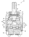
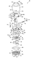
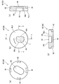
- the base body 68 has a hot water inlet 70, a water inlet 72 and a discharge outlet 74. Under the base body 68, openings corresponding to the hot water inlet 70, the water inlet 72, and the discharge port 74 are provided, and the hot water inlet pipe 18 and the water inlet pipe 20 are respectively provided in these openings. And the discharge pipe 22 is connected.
- the movable valve body 60 has an upper member 86 and a lower member 88.
- the upper member 86 is fixed to the lower member 88. This fixing is achieved by the engagement between the convex portion 90 and the concave portion 92.
- the upper member 86 and the lower member 88 are separate members. By using separate members, the optimum material and manufacturing method can be selected for each of the upper member 86 and the lower member 88.
- the movable valve body 60 may be integrally formed as a whole.
- a smooth surface PL1 is provided on the upper surface of the fixed valve body 62 (see FIG. 8). The portion where the holes 82, 84 and 80 are not present is the smooth surface PL1.
- a smooth surface PL2 is provided on the lower surface of the lower member 88 (movable valve body 60). A smooth surface PL2 is provided in a portion where the flow path forming recess 94 is not formed. A watertight state is ensured by surface contact between the smooth surface PL1 and the smooth surface PL2.
- a lever engaging recess 98 that engages with the lower end 95 of the lever 46 is provided on the upper surface of the upper member 86.
- the lower end 95 of the lever 46 is inserted into the lever engaging recess 98.
- the movable valve body 60 slides on the fixed valve body 62.
- engagement between the lever 46 and the lever engaging recess 98 may be direct or indirect.
- another member may be interposed between the lever 46 and the lever engaging recess 98.
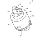
- the large diameter cylindrical portion 122 has an engagement hole 130.
- the engagement hole 130 is engaged with the engagement convex portion 77 of the base body 68. By this engagement, the housing 42 is fixed to the base body 68.
- the large-diameter cylindrical portion 122 accommodates the base portion 102 of the rotating body 44, the movable valve body 60, and the fixed valve body 62.
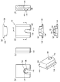
- FIG. 9 (a) to 9 (h) show the shaft holder 54.
- FIG. FIG. 9A is a top view.
- FIG. 9B is a plan view seen from the inside.
- FIG. 9C is a side view.
- FIG. 9D is a plan view seen from the outside.
- FIG. 9E is a bottom view.
- FIG. 9F is a cross-sectional view taken along the line ff in FIG.
- FIG. 9G is a cross-sectional view taken along the line gg in FIG.
- FIG. 9H is a perspective view.
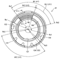
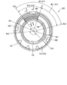
- FIG. 10 is a bottom view of the housing 42 as viewed from below. Therefore, the lower surface 125 of the connecting portion 124 is shown in FIG.
- the lower surface 125 of the connecting part 124 includes a click expression part 146 and a click non-expression part 148. Further, the lower surface 125 includes a first stopper 150 and a second stopper 152.
- the base 102 of the rotating body 44 is in contact with the lower surface 125 of the connecting portion 124. When the rotating body 44 rotates, the base 102 slides on the lower surface 125.
- the first stopper 150 and the second stopper 152 regulate the rotation range of the rotating body 44.
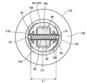
- FIG. 11 is a sectional view taken along line F11-F11 in FIG.
- FIG. 11 is a cross-sectional view of the click mechanism expression unit 146. Note that FIG. 11 is upside down from the normal use state (FIG. 8). That is, in FIG. 11, the lower surface 125 of the connecting portion 124 is the upper side.
- the displacement of the elastic member 58 does not occur.
- the sphere 56 is held by the sphere holding portion 164 while being placed on the elastic member 58. Due to the sphere holding portion 164, the sphere 56 is not misaligned. As shown in FIGS. 12 and 13D, the sphere 56 protrudes upward from the through hole 110 of the rotating body 44 in a state where the rotating body 44 is placed. That is, a part of the sphere 56 is an upward projecting portion that projects from the upper surface of the rotating body 44. This upward projecting portion comes into contact with the lower surface 125 of the connecting portion 124. The lower surface 125 is an abutting surface that can abut against the upward projecting portion.
- the moving direction of the movable valve body 60 is regulated by the rotating body 44. Due to this restriction, the mixing ratio of hot and cold water does not change only by turning the lever back and forth.
- a plurality of movement direction regulating mechanisms are employed.
- the movement direction regulating mechanism is an engagement between the rotating body 44 and the movable valve body 60 (upper member 86).
- the movement direction is more reliably controlled by providing a plurality of movement direction regulating mechanisms for the same movement direction D1.
- the angle range of lever rotation is restricted.
- the first stopper 150 and the second stopper 152 are provided on the lower surface 125 of the connecting portion 124 (see FIG. 10).
- the base portion 102 of the rotating body 44 has an outer extending portion 109 protruding outward in the radial direction (see FIGS. 13D and 8).
- the outer extending portion 109 is provided with the through hole 110 described above.
- the lever turns the outer extending portion 109 moves in the circumferential direction in the range from the first stopper 150 to the second stopper 152. That is, the outer extending portion 109 moves in the circumferential direction in the range from the circumferential positions Rx1 to Ry1 (see FIG. 10).
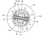
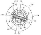
- FIG. 16 is a cross-sectional view similar to FIG. 15, and shows a state where the sphere 52 is engaged with the convex portion 170.
- FIG. 17 is a cross-sectional view similar to FIG. 15 and shows a state where the engagement between the sphere 52 and the convex portion 170 is released.
- FIG. 12 shows a state in which the sphere 56 and the groove 154 are engaged.
- This click B feeling is caused by the engagement or disengagement of the sphere 56 and the groove 154.
- this back-and-forth click feeling is caused by the engagement or disengagement between the sphere 56 and the protrusion 156.
- the lever 46 rotates back and forth, the sphere 56 moves on the click mechanism expression unit 146 in the radial direction.
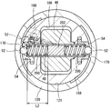
- FIG. 18 is a modification of the embodiment shown in FIGS.
- two elastic members 200 are used instead of the elastic member 50.
- These elastic members 200 are coil springs.
- the longitudinal length of the coil spring 200 is shorter than the longitudinal length of the coil spring 50.
- the embodiment of FIG. 18 has an intermediate member 202.
- the intermediate member 202 is a columnar member.
- the material of the intermediate member 202 is stainless steel.
- the intermediate member 202 serves as a spacer.
- the interval between the two coil springs 200 is set by the intermediate member 202.
- the compression degree of the coil spring 200 can be adjusted by the intermediate member 202.
- the intermediate member 202 is not fixed to the lever shaft 48.
- the intermediate member 202 may be fixed to the lever shaft 48.
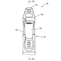
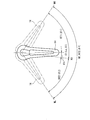
- FIG. 19 is a plan view for explaining the turning (left-right rotation) of the handle 14.
- the handle 14 can turn from the left limit ML to the right limit MR.
- the swivelable range RF of the handle 14 corresponds to the angle range Rf of FIG. 10 described above.
- the angle ⁇ f of the range RF is equal to the angle ⁇ f of the range Rf.
- the handle 14 faces the front.
- This central circumferential position C1 corresponds to the central circumferential position c1 in FIG.
- the turning range of the handle 14 is symmetrical with respect to the front position S1.
- the angle range RT1 is on the right side of the center circumferential position C1 when viewed from the user.
- This angle range RT1 corresponds to the angle range Rt1 in FIG.
- the angle ⁇ 1 of the range RT1 is equal to the angle ⁇ 1 of the range Rt1. Therefore, the angle range RT1 is freely set by the arrangement of the click non-expressing part 148.
- the circumferential position of the handle 14 is in the angle range RT1
- hot water is not mixed. That is, when the circumferential position of the handle 14 is in the angle range RT1, the ratio of water is 100%.
- Range RT1 is a water discharge position. In the present embodiment, hot water is not mixed when the handle 14 is on the right side of the front.
- the position C1 is a water discharge position.
- the angle range RT2 is on the left side of the center circumferential position C1 when viewed from the user.
- This angle range RT2 corresponds to the angle range Rt2 in FIG.
- the angle ⁇ 2 of the range RT2 is equal to the angle ⁇ 2 of the range Rt2. Therefore, the angle range RT2 is freely set by the arrangement of the click mechanism expression unit 146.
- the circumferential position of the handle 14 is in the angle range RT2
- hot water and water are mixed, or water is not mixed (hot water is 100%). That is, when the circumferential position of the handle 14 is in the angle range RT2, the ratio of water is 0% or more and less than 100%.
- Range RT2 is a hot water mixing discharge position and a hot water discharge position.
- the turnable range RF of the handle 14 is symmetric with respect to the front position S1, but it may be asymmetrical.
- the angle ⁇ 2 of the angle range RT2 may be 60 degrees
- the angle ⁇ 1 of the angle range RT1 may be 40 degrees.
- the angle ⁇ 2 of the range RT2 is preferably 40 degrees or more, more preferably 50 degrees or more, and particularly preferably 55 degrees or more. If the angle range RT2 is too large, the angle range of the handle 14 that can adjust the hot / cold water mixing ratio becomes too wide, and the operability deteriorates. From this viewpoint, the angle ⁇ 2 of the range RT2 is preferably 100 degrees or less, more preferably 90 degrees or less, and particularly preferably 70 degrees or less.
- the angle ⁇ 1 of the angle range RT1 can be 0 degree. However, since the angle ⁇ 1 is not set to 0 degrees in a normal hot and cold water mixing tap, if ⁇ 1 is set to 0 degrees, the user may excessively operate the handle 14 to the right side of the center circumferential position C1. is there. Repeating this excessive operation may place an excessive burden on the hot / cold mixing tap and adversely affect the durability of the hot / cold mixing tap.
- the angle ⁇ 1 of the range RT1 is preferably 10 degrees or more, more preferably 20 degrees or more, and particularly preferably 30 degrees or more. When the angle ⁇ 1 is excessive, the range in which the ratio of water is 100% becomes too wide and the operability is deteriorated. In this respect, the angle ⁇ 1 of the range RT1 is preferably 70 degrees or less, more preferably 60 degrees or less, and particularly preferably 50 degrees or less.
- the angle ratio ( ⁇ 1 / ⁇ 2) between the angle range RT1 and the angle range RT2 is preferably equal to or greater than 0.2, more preferably equal to or greater than 0.4, and particularly preferably equal to or greater than 0.6.
- the angle ratio ( ⁇ 1 / ⁇ 2) is preferably 0.9 or less, more preferably 0.8 or less, and particularly preferably 0.7 or less.
- the angle range RT1 is on the right side of the center circumferential position C1 as viewed from the user, and the water ratio is 100% on the right side of the center circumferential position C1.
- the angle range RT2 is set to the left side of the central circumferential position C1 when viewed from the user, and the ratio of water is set to 0% or more and less than 100% on the left side of the central circumferential position C1.
- the ratio of water is 0% or more and less than 100% on the right side of the center circumferential position C1. Even in this case, all of the numerical values described above regarding the angle ⁇ 1, the angle ⁇ 2, and / or the angle ratio ( ⁇ 1 / ⁇ 2) can be applied. However, as will be described later, the relationship between the lever circumferential position and the mixing ratio of hot water can be set in various ways, and an effect commensurate with each setting can be achieved.
- the click mechanism expression part 146 is provided in the entire range of the angle range Rt2. Therefore, when the lever left-right position is in the angle range RT2, the back-and-forth click mechanism works. On the other hand, the click mechanism expression part 146 is not provided in the whole range of the angle range Rt1. The entire range of the angle range Rt1 is the click non-expression part 148. Therefore, when the lever left-right position is in the angle range RT1, the back-and-forth click mechanism does not work.
- the back-and-forth click feeling does not appear in the back-and-forth rotation operation at the lever left-right position where hot water is not mixed. Moreover, in the lever left-right position where hot water is mixed, a back-and-forth click feeling is expressed by a forward-backward rotation operation. Therefore, if a back-and-forth rotation operation is performed, whether hot water is mixed or not is determined based on the presence or absence of a back-and-forth click feeling.
- there are various settings for the back-and-forth click feeling and an effect commensurate with each setting can be achieved.
- the determination of whether hot water is mixed or not can also be achieved by the left-right click feeling accompanying the lever turning.
- a left-right click feeling appears at a boundary K1 (see FIG. 19) between the left-right position where only water discharges and the left-right position where hot water is mixed.
- Whether or not hot water is mixed is determined based on the left and right click feeling.
- a left-right click feeling appears at the boundary between the angle range RT1 and the angle range RT2.
- FIG. 20A is a plan view of the fixed valve body 62.
- Fig.20 (a) is the figure which looked at the fixed valve body 62 from the upper side.
- FIG. 20B is a bottom view of the fixed valve body 62.
- FIG. 20B is a view of the fixed valve body 62 as viewed from below.
- 20 (c) is a cross-sectional view taken along the line cc of FIG. 20 (a)
- FIG. 20 (d) is a cross-sectional view taken along the line dd of FIG. 20 (a).
- 20 (e) is a cross-sectional view taken along the line ee of FIG. 20 (a)
- FIG. 20 (f) is a cross-sectional view taken along the line ff of FIG. 20 (a).
- FIG. 20G is a cross-sectional view taken along the line gg in FIG.
- the hot water valve hole 80 (upper surface opening line 80L) is a bent long hole.
- the water valve hole 82 (upper surface opening line 82L) is also a bent long hole.
- the hot water valve hole 80 has an upper surface opening line 80L.
- Upper surface opening line 80L is the opening shape of hot water valve hole 80 in smooth surface PL1.
- the water valve hole 82 has an upper surface opening line 82L.
- Upper surface opening line 82L is the opening shape of water valve hole 82 in smooth surface PL1.
- the mixed water valve hole 84 has an upper surface opening line 84L.
- the upper surface opening line 84L is the opening shape of the mixed water valve hole 84 in the smooth surface PL1.
- the hot water valve hole 80 has a lower surface opening line 80s.
- the water valve hole 82 has a lower surface opening line 82s.
- the mixed water valve hole 84 has a lower surface opening line 84s.
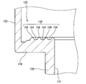
- the water valve hole 82 has a first wall surface portion W1 at one end in the longitudinal direction thereof.
- the water valve hole 82 has a second wall surface portion W2 at the other end in the longitudinal direction.
- the hot water valve hole 80 has a third wall surface portion W3 at one end in the longitudinal direction thereof.
- the hot water valve hole 80 has a fourth wall surface portion W4 at the other end in the longitudinal direction thereof.
- the first wall surface portion W1 has an inclined surface SL1.
- the second wall surface portion W2 has an inclined surface SL2.
- the third wall surface portion W3 has an inclined surface SL3.
- the fourth wall surface portion W4 has an inclined surface SL4.
- the wall surface of the hot water valve hole 80 has the inclined surfaces SL3 and SL4.
- the wall surface of the water valve hole 82 has inclined surfaces SL1 and SL2.
- the inclined surfaces SL1 to SL4 suppress this rapid inflow. Therefore, water hammer is suppressed. Since hot water or water flows obliquely along the inclined surface, the impact of water pressure is alleviated.
- inclined surfaces SL1 to SL4 may be flat surfaces or curved surfaces.
- the inclined surfaces SL1 to SL4 may be smooth or may be stepped (for example, stepped).
- the upper surface opening line 80L of the hot water valve hole 80 and the upper surface opening line 82L of the water valve hole 82 are asymmetrically formed. That is, in the plan view of FIG. 20A, there is no symmetry axis where the upper surface opening line 80L and the upper surface opening line 82L overlap when the figure is reversed with a certain straight line as an axis.
- the upper opening line 80L and the upper opening line 82L have no symmetry with respect to the lever front-rear direction center line Lc (see FIGS. 20A and 20B).
- the lever front-rear direction center line Lc coincides with the center line of the lever 46 when the lever 46 is at the center circumferential position C1 (see FIG. 19).
- One method for increasing the degree of freedom of the hot water switching function is to design various positional relationships between the flow path forming recess 94, the hot water valve hole 80, and the water valve hole 82.
- the design freedom of the hot water valve hole 80 and the water valve hole 82 is improved by not being limited to the above-described symmetrical configuration. Therefore, various hot and cold water switching functions can be realized without causing a large cost increase.
- the hot water valve hole 80 and the water valve hole 82 have been arranged symmetrically.
- the inclined surface SL is not provided on the side surfaces of the hot water valve hole 80 and the water valve hole 82, and the side surface of the hot water valve hole 80 is perpendicular to the smooth surface PL1.
- the upper surface opening line and the lower surface opening line were in the same position and in the same shape.
- the upper surface opening line and the lower surface opening line were in the same position and in the same shape.
- the lower surface opening line also has a special shape.
- the widely used base body 68 does not conform to the lower surface opening line. That is, a situation occurs in which the general-purpose base body 68 cannot be used.
- the shape and arrangement of the upper surface opening line 80L and the lower surface opening line 80s are different. Further, the shape and position of the upper surface opening line 82L and the lower surface opening line 82s are different. The aforementioned inclined surfaces SL1 to SL4 cause these differences.
- the shape of the lower surface opening lines 80s and 82s can be adapted to the general-purpose base body 68 while increasing the design freedom of the upper surface opening lines 80L and 82L. From this viewpoint, it is preferable that the lower surface opening line 82s and the lower surface opening line 80s are symmetric (see FIG. 20B).
- the lower surface opening line 82s and the lower surface opening line 80s are symmetric (left-right symmetric), and the axis of symmetry is the lever front-rear direction center line Lc.
- FIG. 21A is a plan view of the lower member 88 of the movable valve body 60.
- FIG. 21A is a view of the lower member 88 as viewed from above.
- FIG. 21B is a bottom view of the lower member 88.
- FIG. 21B is a view of the lower member 88 as viewed from below.
- FIG. 21C is a cross-sectional view taken along the line cc in FIG.
- FIG. 21D is a cross-sectional view taken along the line dd in FIG.
- the flow path forming recess 94 has a lower surface opening line 94L.
- the lower surface opening line 94L is the opening shape of the flow path forming recess 94 in the smooth surface PL2.
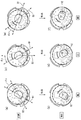
- 22 (a) to 22 (f) are diagrams showing an overlapping state of the upper surface of the fixed valve body 62 and the lower surface of the movable valve body 60 (lower member 88).
- 22 (a) to 22 (f) the line of the movable valve body 60 hidden by the fixed valve body 62 in the upper view is drawn with a broken line, and the lower surface line of the movable valve body 60 (lower member 88) is shown. It is drawn with a solid line.
- 22A to 22F the upper surface opening line 80L, the upper surface opening line 82L, and the lower surface opening line 94L are overlapped.
- FIG. 22A shows a state where the lever left-right position is the left limit ML and the lever front-rear position is the upper limit (discharge stop).
- FIG. 22B shows a state in which the lever left-right position is the left limit ML and the lever front-rear position is the lower limit (discharge maximum).
- FIG. 22C shows a state where the lever left-right position is the center circumferential position C1 (front position S1), and the lever front-rear position is the upper limit (discharge stop).
- FIG. 22D shows a state where the lever left-right position is the center circumferential position C1 (front position S1) and the lever front-rear position is the lower limit (maximum discharge).
- FIG. 22A shows a state where the lever left-right position is the left limit ML and the lever front-rear position is the upper limit (discharge stop).
- FIG. 22B shows a state in which the lever left-right position is the left limit ML and the lever front-rear position is
- FIG. 22 (e) shows a state where the lever left-right position is the right limit MR and the lever front-rear position is the upper limit (discharge stop).
- FIG. 22F shows a state in which the lever left-right position is the right limit MR, and the lever front-rear position is the lower limit (maximum discharge position).
- the region X surrounded by the upper surface opening line 80L is indicated by broken line hatching in FIG.
- This region X is an upper surface opening region of the hot water valve hole 80.
- a region Y surrounded by the upper surface opening line 82L is indicated by broken line hatching in FIG.
- This region Y is an upper surface opening region of the water valve hole 82.
- a region Z surrounded by the lower surface opening line 94L is indicated by broken line hatching in FIG.
- This region Z is a lower surface opening region of the flow path forming recess 94 in the movable valve body 60 (lower member 88).
- the solid line hatching indicates an overlapping region XZ between the region X and the region Z.
- the hatching in FIG. 22D shows an overlapping area YZ between the area Y and the area Z.
- the hatching in FIG. 22 (e) indicates an overlapping region YZ between the region Y and the region Z.
- the region E of the mixed water valve hole 84 overlaps the region Z of the flow path forming recess 94.
- the hot water reaches the hot water valve hole 80 via the hot water introduction section (the hot water introduction pipe 18 and the hot water introduction port 70).
- the water reaches the water valve hole 82 through the water introduction part (the water introduction pipe 20 and the water introduction port 72).
- Hot water and / or water that has reached the flow path forming recess 94 reaches the discharge section 16 via the mixed water valve hole 84, the discharge port 74, and the discharge pipe 22.
- the mixing ratio of hot water and water depends on the area ratio R1 between the region XZ and the region YZ.
- the movable valve body 60 rotates via the lever 46.
- the area ratio R1 changes. This change adjusts the water temperature.
- the discharge amount depends on the total area Sa of the region XZ and the region YZ.
- the lever 46 rotates back and forth, and the movable valve body 60 moves in the linear direction D1. Due to the movement of the movable valve body 60, the total area Sa changes.
- the discharge amount is adjusted by this change.
- the hot and cold water mixing tap 10 has a discharge amount adjusting mechanism that can adjust the discharge amount by rotating the lever 46 back and forth.
- the case where the total area Sa is zero means that the hot water valve hole 80 and the water valve hole 82 are completely closed by the smooth surface PL2.
- An example in which the hot water valve hole 80 and the water valve hole 82 are completely closed by the smooth surface PL2 is shown in FIGS. 22 (a), (c) and (e).
- the region YZ does not exist.
- the lever left-right position is the left limit ML
- water is not mixed regardless of the lever vertical rotation position. That is, in this case, hot water is 100%.
- the double arrow D1 indicates the linear direction of movement of the movable valve body 60. Therefore, in FIGS. 22A to 22F, the lower surface opening line 94L moves along the linear direction D1.
- the front-rear direction D2 is the front-rear rotation direction of the lever 46 in plan view as viewed from above.
- the front-rear direction D2 is a direction perpendicular to the central axis of the lever 46 that pivots back and forth (the central axis of the lever shaft 48).
- the front-rear direction D2 is parallel to the intersection line Lm.
- the movable valve body 60 moves in the front-rear direction D2, a region XZ is generated in the discharge state of FIG. That is, hot water is mixed by this region XZ.
- the linear direction D1 is inclined with respect to the front-rear direction D2. And the direction of this inclination is a direction which avoids duplication with the valve hole 80 for hot water in the state whose lever right-and-left position is the center periphery position C1.
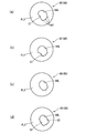
- FIG. 24A is a plan view showing the shape of the lower surface opening line 94L.
- the lower surface opening line 94L has a straight portion ST.
- the straight portion ST is parallel to the linear direction D1 (see FIGS. 23A, 23C, and 23E).
- the lower surface opening line 94L is disposed on the hot water valve hole 80 side.
- the straight portion ST In a state where the discharge amount is the maximum, when shifting from a state where only water is discharged to a state where hot water is mixed, it is this straight shape that first overlaps the upper surface opening line 80L among the lower surface opening lines 94L.
- Part ST In other words, in the process of turning the lever 46 from the state of FIG. 22D to the state of FIG. 22B, the straight portion ST first overlaps the upper surface opening line 80L.
- Such arrangement of the straight portion ST contributes to preventing mixing of hot water when the lever left-right position is the center circumferential position C1 (see FIG. 23 (d)).
- the straight portion ST is preferably substantially parallel to the linear direction D1.
- substantially parallel is intended to allow an error angle of ⁇ 5 degrees.
- the error angle is preferably ⁇ 3 degrees, and more preferably, the straight portion ST and the linear direction D1 are parallel to each other as in the above embodiment.
- the straight part ST is not a straight line, the error angle and the parallelism are determined by a straight line connecting both ends of the straight part ST.
- the improvement in the degree of freedom in designing the valve hole makes it easy to provide the movable valve body 60 and the fixed valve body 62 with a front-rear click mechanism and / or a left-right click mechanism.
- the generation of the region XZ (see FIG. 23A) is controlled by making the linear direction D1 different from the front-rear direction D2. For this reason, the restriction of the valve hole shape can be reduced. Therefore, the degree of freedom in designing the valve hole shape is improved. This improvement in the degree of design freedom improves the degree of freedom in setting the relationship between the hot / cold water mixing ratio and the lever turning operation. In addition, the degree of freedom is improved in setting the relationship between the discharge amount and the lever back-and-forth rotation operation.
- the supply pressure of hot water supplied to the hot water valve hole 80 is lower than the supply pressure of water supplied to the water valve hole 82. This is due to the fact that the hot water reaches the hot water mixing tap 10 via the hot water supply device.
- the region XZ (FIG. 23B) is likely to increase with a small turning angle in the turning to the hot water side (turning to the left in FIG. 19).
- the mixing ratio of hot water tends to increase. Therefore, it is possible to suppress a situation in which the water discharge temperature is unlikely to rise despite being in the lever left and right positions where hot water is mixed. For this reason, the hot and cold water mixing tap 10 with easy temperature control can be realized.
- the length of the lower surface opening line 94L in the direction parallel to the linear direction D1 is Lf.
- the straight portion ST means a portion formed by a line having a radius of curvature that is equal to or greater than twice the length Lf.
- the radius of curvature may change.
- the straight portion ST is preferably formed by a line having a radius of curvature of three or more times the length Lf, and the most preferable shape of the straight portion ST is a straight line. is there.
- the radius of curvature of the straight portion ST can be 20 mm or more, further 25 mm or more, for example, 28 mm.
- the angle ⁇ x (see FIG. 23) is preferably 5 degrees or more and preferably 10 degrees or more from the viewpoint of preventing mixing of hot water when the lever left-right position is the center circumferential position C1 and increasing the degree of freedom in designing each valve hole. Is more preferable, and 20 degrees or more is particularly preferable. From the viewpoint of facilitating the forward and backward rotation operation of the lever 46, the angle ⁇ x is preferably 45 degrees or less, more preferably 40 degrees or less, and particularly preferably 35 degrees or less. In the present embodiment, the angle ⁇ x is 30 degrees.
- the convex part m1 is provided in the lower surface opening line 94L.
- the convex portion m1 can alleviate a rapid inflow of hot water or water into the flow path forming concave portion 94 when shifting from the water stop state to the discharge state. Therefore, these convex-shaped parts m1 contribute to suppression of a water hammer.
- FIGS. 24B, 24C, and 24D are modified examples of the lower surface opening line 94L.
- the straight portion ST may not be provided.
- straight portions ST may be provided on both the hot water valve hole 80 side and the water valve hole 82 side.
- the water discharge specification can be changed.
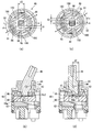
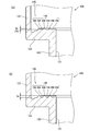
- FIGS. 25 (a) and 25 (b) are cross-sectional views of the lever assembly 40 in the water discharge state.
- FIG. 25A is a cross-sectional view along the upper surface of the upper member 86
- FIG. 25B is a cross-sectional view along the vertical direction of the shaft hole 100 of the lever 46.
- FIGS. 25C and 25D are cross-sectional views of the lever assembly 40 in a water stop state.
- FIG. 25C is a cross-sectional view along the upper surface of the upper member 86
- FIG. 25D is a cross-sectional view along the vertical direction of the shaft hole 100 of the lever 46.
- the description of members inside the shaft hole 100 is omitted.
- a gap Gp is provided between the lower end portion (hatched portion) of the lever 46 and the lever engaging recess 98.
- the movement direction of the lower end portion of the lever 46 is the front-rear direction D2 by the front-rear rotation of the lever 46, but the movement direction of the movable valve body 60 (upper member 86) is the linear direction D1.
- the gap Gp allows the movable valve body 60 to move along the linear direction D1.
- the linear direction D1 and the front-rear direction D2 are different due to the presence of the gap Gp, the lower end of the lever 46 does not hinder the movement of the movable valve body 60.
- the gap Gp exists on the right side and the left side of the lever 46 when viewed from the user side of the hot water mixing tap 10.
- G1 is the gap distance on the right side of the lever 46.
- G2 indicates the gap distance on the left side of the lever 46. [G1 + G2] is constant regardless of the position of the lever 46 in the vertical direction.
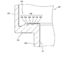
- the lever engaging recess 98 has a first side surface 98a and a second side surface 98b (see FIGS. 13 (a), 25 (b) and 25 (d)).
- the first side surface 98a is a plane.
- the second side surface 98b is a plane.
- the lower end of the lever 46 has a first curved surface Rs1 and a second curved surface Rs2.
- the first curved surface Rs1 and the second curved surface Rs2 are convex curved surfaces.
- the contact position moves as the lever rotates back and forth, but the first curved face Rs1 and the second curved face Rs2 reduce the frictional resistance accompanying the movement of the contact position. Therefore, smooth lever operation is realized.
- the cross section line of the first curved surface Rs1 is an arc (referred to as an arc 1), and the radius of the arc 1 is defined as r1.
- the cross section line of the second curved surface Rs2 is an arc (arc 2), and the radius of the arc 2 is r2.
- the radius r1 is equal to the radius r2.
- the center of the arc 1 and the center of the arc 2 are the same. That is, the arc 1 and the arc 2 are on the same circumference.
- the double arrow d1 indicates the diameter of a circle including the arc 1 and the arc 2.
- a double arrow d3 indicates the distance between the first side surface 98a and the second side surface 98b.
- the difference (d3 ⁇ d1) is preferably 0.2 mm or less, more preferably 0.1 mm or less, and particularly preferably 0.05 mm or less.
- the difference (d3 ⁇ d1) is preferably 0 mm or more, more preferably 0.01 mm or more, and particularly preferably 0.02 mm or more.
- the first curved surface Rs1 and the second curved surface Rs2 are both part of the same cylindrical surface (hereinafter referred to as a virtual cylindrical surface).
- the central axis Cz of the virtual cylindrical surface is perpendicular to the front-rear direction D2.
- the central axis Cz is parallel to the central axis of the lever 46 that rotates forward and backward. Even if the movable valve body 60 moves along the linear direction D1, the first side surface 98a and the second side surface 98b are always in contact with the virtual cylindrical surface. That is, the contact between the first side surface 98a and the first curved surface Rs1 is maintained even though the linear direction D1 and the front-rear direction D2 are different.
- the contact between the second side surface 98b and the second curved surface Rs2 is maintained even though the linear direction D1 and the front-rear direction D2 are different. Moreover, these contacts are always line contacts. Accordingly, the difference between the linear direction D1 and the front-rear direction D2 is realized, and stable contact between the lever engaging recess 98 and the lower end portion of the lever 46 is maintained over the entire vertical rotation range of the lever. ing. Moreover, since the contact form is a line contact, the frictional resistance is suppressed. The direction of these line contact lines is along the relative movement direction between the side surfaces 98a and 98b and the curved surfaces Rs1 and Rs2. Therefore, the frictional resistance is suppressed. With these configurations, the lever 46 can be rotated back and forth smoothly and stably.
- the depth of the recess 96 is such that the lower end of the lever 46 and the movable valve body 60 (upper member 86) do not contact with each other in the entire range of forward and backward rotation of the lever 46. Is set to This facilitates the operation of turning the lever 46 back and forth.
- the click feeling in the front-rear rotation differs depending on the lever left-right position.
- the difference between the front and rear click feelings is the presence or absence of the front and rear click feeling.
- the presence or absence of a back-and-forth click feeling is easy to distinguish.
- whether hot water is mixed or not is easily determined based on the presence or absence of a back-and-forth click feeling.
- hot water may be mixed based on the temperature of the water discharge alone. For example, when the mixing ratio of hot water is small, the temperature is not so high as compared with the case where water is 100%. Therefore, in this case, mixing of hot water may not be noticed only from the temperature of the discharged water. Even when the mixing ratio of hot water is high, the temperature of the discharged water may not rise until the hot water heated by a heating device such as a water heater reaches the faucet. Also in this case, the mixing of hot water may not be noticed only from the temperature of the discharged water. Also, depending on the circumferential position of the handle 14, it may not be possible to accurately determine whether hot water is mixed. In such a case, hot water may be mixed against the user's intention.
- hot water may actually be mixed. In this case, energy is wasted.
- whether hot water is mixed or not is easily determined based on the presence or absence of a back-and-forth click feeling. Therefore, waste of energy is suppressed.
- the angle range in which the click feeling is generated can be freely designed.
- the position of the click mechanism expression unit 146 the left / right position of the lever where the back-and-forth click feeling is expressed can be freely changed (see FIG. 10). Therefore, for example, the click mechanism expression unit 146 and the click non-expression unit 148 in FIG. 10 can be interchanged. In this case, the back-and-forth click feeling does not appear in the hot water mixed discharge range, and the back-and-forth click feeling appears in the water discharge range.
- the click mechanism expression unit 146 can be provided, for example, in the angle range Rf2 (see FIG. 10). Therefore, the click mechanism expression unit 146 may be provided only in the angle range Rf as in the present embodiment, may be provided in both the angle range Rf and the angle range Rf2, or may be provided only in the angle range Rf2. . Therefore, the degree of freedom in designing the back-and-forth click feeling and the left-right click feeling is high.
- the area of the lower surface of the housing 42 is relatively large. Therefore, the degree of freedom in designing the recesses and / or protrusions is high. By providing the housing 42 with a concave portion and / or a convex portion, the degree of freedom in designing the click feeling is enhanced.
- the click mechanism expression part 146 is not intermittent in the circumferential direction. Unlike this, the click mechanism expression part 146 may be provided intermittently in the circumferential direction. In this case, it is possible to intermittently provide a lever left-right position that produces a back-and-forth click feeling.
- the click mechanism expression part 146 is provided in the entire lever front-rear rotation range. Unlike this, the click mechanism expression part 146 may be provided in a part of the lever front-rear rotation range. In this case, the lever front-rear range in which the front-rear click feeling is expressed can be limited.
- the click feeling can be designed freely.
- various click feelings can be obtained by changing the number, interval, shape, height, and the like of the grooves 154 or the protrusions 156.
- the number of grooves 154 and / or protrusions 156 can determine the number N of times described below.
- the back-and-forth click feeling and the left-right click feeling can be set in various ways. Therefore, setting of the back-and-forth click feeling and the right-and-left click feeling can be facilitated.
- Other modifications of the click mechanism expression unit 146 will be described later.
- the presence or absence of a click feeling is easy to distinguish for the user.
- An example of the difference in click feeling is the presence or absence of a click feeling.
- the following is exemplified as the setting for the presence or absence of a click feeling.
- the following setting 1 is a setting in the above-described embodiment. Below, the mixing ratio of hot water and water is shown as a percentage (%).
- [Setting 1] There is no back-and-forth click feeling at the lever left-right position where the mixing ratio of water is 100%. In the lever left-right position where the mixing ratio of water is less than 100%, a back-and-forth click feeling is generated.
- [Setting 2] A front-rear click feeling is generated at the lever left-right position where the mixing ratio of water is 100%. In the lever left-right position where the water mixing ratio is less than 100%, there is no back-and-forth click feeling.
- the mixing ratio Wa% may be set to a ratio at which the water temperature becomes dangerous when directly touched by a human body, for example. In this case, whether or not hot hot water is discharged can be sensed by a click feeling.
- the number N is 3 or less at a certain lever left-right position, and the number N is 4 or more at another lever left-right position.
- the resistance feeling is relatively small at a certain lever left-right position, and the resistance feeling is relatively large at another lever left-right position.
- the frequency of the sound is relatively high at a certain lever left-right position, and the sound frequency is relatively low at another lever left-right position.
- the diameter Pa of the sphere 52 is preferably 1.0 mm or more, more preferably 2.0 mm or more, and even more preferably 3.0 mm or more.
- the diameter Pa is preferably 5.0 mm or less, and more preferably 4.0 mm or less.
- the diameter Pa of the sphere 52 is set to 3.0 mm.
- 28 (a) and 28 (b) show a housing 420 according to a modification.
- the difference between the housing 420 and the housing 42 described above is only the cross-sectional shape of the click mechanism expression portion 146.
- FIG. 28A is a cross-sectional view taken along the line AA in FIG.
- FIG. 28B is a cross-sectional view taken along the line BB in FIG.
- the depth Dv of the groove 154 (the height Hb of the protrusion 156) differs depending on the circumferential position.
- the depth Dv in FIG. 28B is larger than the depth Dv in FIG.
- the back-and-forth click feeling is different due to the difference in the depth Dv.
- the greater the depth Dv the greater the back-and-forth click feeling (for example, operational resistance, vibration, sound, or a combination thereof).
- the difference in the depth Dv can be set in various ways.
- the depth Dv may change gradually (continuously) in the circumferential direction, or may change stepwise (non-continuously) in the circumferential direction. Further, the depth Dv may increase as the temperature increases, or the depth Dv may increase as the temperature decreases.
- the configuration of the housing 420 and the configuration of the housing 421 may be combined. That is, the depth Dv may be different depending on the circumferential position and may be different depending on the radial position. By this combination, various click feelings can be expressed.
- the height of the convex portion 170 differs depending on the circumferential position.
- it has the convex part 170a which has 1st height H1, the convex part 170b which has 2nd height H2, and the convex part 170c which has 3rd height H3.
- the magnitude relationship between the heights is H3>H2> H1.
- the aspect of the height difference is not limited, and examples thereof include H3 ⁇ H2 ⁇ H1, H3 ⁇ H2> H1, and H3> H2 ⁇ H1.
- the left-right click feeling can be increased as the temperature increases, or the left-right click feeling can be increased as the temperature decreases. Further, the left-right click feeling can be maximized at a specific lever left-right position.
- Various left and right click feelings can be obtained by changing the number and height of the convex portions. Of course, it may replace with the convex part from which height differs, and the recessed part from which depth differs may be employ
- the members constituting the lever assembly 40 can be classified into the following three types.
- Member X A member that rotates in conjunction with the left-right rotation of the lever and moves in conjunction with the front-rear rotation of the lever.
- Member Y A member that rotates in conjunction with the left-right rotation of the lever, but does not move due to the front-rear rotation of the lever.
- Fixing member Z a member that does not move (does not move or rotate) with respect to any operation of the lever.
- the movable valve body 60 (the upper member 86 and the lower member 88) may be mentioned as the member X in (1) above.
- a rotating body 44 is exemplified.
- Examples of the fixing member Z of (3) include a housing 42, a fixed valve body 62, and a base body 68.
- the back-and-forth click feeling can be made different depending on the lever left-right position.
- the back-and-forth click mechanism is realized by the engagement between the member X and the fixing member Z.
- the degree of freedom in designing the click feeling it is preferable that the degree of freedom in design of the recesses and / or protrusions is high. From this viewpoint, it is preferable that the installation area of the concave portion and / or the convex portion is wide. From the viewpoint of the installation area, the concave portion and / or the convex portion are preferably provided in the fixing member Z, and more preferably provided in the housing 42.
- the movable valve body 60 (upper member 86) is employed as an example of the member X related to the front-rear click mechanism.
- the housing 42 is employed as an example of the fixing member Z related to the back-and-forth click mechanism.
- a combination of an elastic body and a contact member (sphere) is employed as an example of a retracting mechanism.
- the following modes (A) and / or (B) can be realized by providing a plurality of concave portions and / or convex portions and varying the depth of the concave portions and / or the height of the convex portions.
- the back-and-forth click feeling differs depending on the lever left-right position.
- the back-and-forth click feeling differs depending on the lever front-rear position.
- the back-and-forth click mechanism can be configured between members that move relative to each other as the lever rotates back and forth. Therefore, the combination of the member X and the fixing member Z for configuring the back-and-forth click mechanism is not limited to the above embodiment.
- a back-and-forth click mechanism may be configured between the movable valve body 60 (lower member 88) and the fixed valve body 62.
- the left-right click mechanism can be configured between members that rotate relative to each other as the lever rotates left and right, for example.
- Examples of the relatively rotating member include a combination of the member Y and the fixing member Z.
- a left-right click mechanism is configured between the member Y and the fixed member Z.
- a left and right click mechanism can be realized by providing a concave portion and / or a convex portion and a retracting mechanism between the member Y and the fixing member Z.
- the rotating body 44 is employed as an example of the member Y related to the left-right click mechanism.
- the housing 42 is employed as an example of the fixing member Z related to the left-right click mechanism.
- the following mode (D) is also possible.
- D The left-right click feeling differs depending on the lever front-rear position.
- An example of a configuration that can realize this mode (D) is the following (Dx).
- Dx In the embodiment shown in FIGS. 10 and 11, a convex portion and / or a concave portion is provided inside the groove 154, and the circumferential position and / or shape of the convex portion and / or the concave portion is different for each groove 154. Make it.
- the member X and the fixing member Z are preferably in direct contact with each other. Other members may be interposed therebetween.
- a back-and-forth click mechanism using relative movement between the member X and the fixing member Z can be realized by providing a through hole in the other member, for example.
- An example of the through hole is the above-described through hole 110.
- the left-right click mechanism between the member Y and the fixed member Z may be possible even if the member Y and the fixed member Z are not in direct contact.
- Sense of click is perceived by people.
- the click feeling can provide the user with various information that cannot be obtained visually.
- the click feeling is sensed by hearing and / or tactile sense. From the viewpoint of enhancing the sensitivity, hearing and touch may be used in combination. Sound is an example of a sense of click sensed by hearing. Examples of the click feeling detected by tactile sensation include change in resistance and vibration during lever operation. The duration of the click feeling is not limited.
- a typical click feeling includes a resistance change and a sound for a relatively short time, but a click feeling for a relatively long time is also possible.
- Examples of the click feeling related to the information 1 include the following. [1a]: Left-right click feeling that informs that the water discharge temperature is high [1b]: Left-right click feeling that informs that the water discharge is only water (no hot water is mixed) [1c]: Change in the water discharge temperature stepwise Multiple left and right click feelings to be notified [1d]: Click feeling before and after notifying that water discharge temperature is high [1e]: Click feeling before and after notifying that water discharge is only water (no hot water mixed)
- Examples of the click feeling related to the information 2 include the following. [2a]: A click feeling before and after notifying that the discharge amount at which the water heater operates is reached [2b]: A plurality of click feelings before and after informing a change in the discharge amount step by step
- Examples of the click feeling related to the information 3 include the following. [3a]: Left-right click feeling expressed at the boundary K1 [3b]: Left-right click feeling expressed near the boundary K1
- the left-right click feeling 3a can contribute to energy saving, for example.
- the left-right click feeling 3b can contribute to energy saving, for example.
- Examples of the vicinity of the boundary K1 in 3b are within ⁇ 10 degrees of the boundary K1, within ⁇ 7 degrees of the boundary K1, within ⁇ 5 degrees of the boundary K1, within ⁇ 3 degrees of the boundary K1, and the like.
- Examples of the information related to the information 4 include the following. [4a]: Front / rear click feeling informing that the lever front / rear position is approaching the maximum discharge position [4b]: Front / rear click feeling informing that the lever front / rear position is the maximum discharge position
- the back-and-forth click feeling 4a and 4b can contribute to alleviating the impact when the lever reaches the limit position, for example. This mitigation of impact can suppress deterioration associated with repeated use.
- Examples of the information related to the information 5 include the following. [5a]: Left-right click feeling that informs that the lever left-right position is approaching the right limit MR [5b]: Left-right click feeling that informs that the lever left-right position is approaching the left limit ML [5c]: Lever left-right position is Left-right click feeling that informs that it is the right limit MR [5d]: Left-right click feeling that informs that the lever left-right position is the left limit ML
- the following (A), (B), (C) and (D) are exemplified as the difference in the click feeling.
- a more preferable aspect is at least one selected from (A), (B) and (C), or a combination of two or more.
- the aspect (B) can have various effects.
- This aspect (B) can give the user information about the discharge amount. For example, making the back-and-forth click feeling more conspicuous as the discharge amount increases helps to save water resources and / or energy. Moreover, adjustment of the amount of water discharge can be made easy.
- This aspect (C) can have various effects.
- This aspect (C) can give a user the information regarding water discharge temperature (mixing ratio of hot water). For example, if the left-right click feeling becomes more prominent as the mixing ratio of hot water increases, it helps to save energy. Further, the water discharge temperature can be easily adjusted.
- the back-and-forth click feeling is different between the water discharge position (100% water) and the hot water mixing discharge position (including 100% hot water).
- A2 The back-and-forth click feeling is different between the water discharge position (100% water), the hot water mixing discharge position with a high water ratio, and the hot water mixing discharge position (including 100% hot water) with a low water ratio.
- A3 The back-and-forth click feeling is different between the water discharge position (water 100%), the hot water mixing discharge position (not including 100% hot water), and the hot water discharge position (hot water 100%).
- (A4) Click back and forth between a water discharge position (100% water), a hot water mixing discharge position with a high water ratio, a hot water mixing discharge position with a low water ratio, and a hot water discharge position (100% hot water).
- the feeling is different.
- the back-and-forth click feeling is different between the water discharge position (water 100%), the hot water mixing discharge position with high usage frequency, and the hot water mixing discharge position (including 100% hot water) with low usage frequency. .
- (A6) Water discharge position (100% water), hot water mixing discharge position with high usage frequency, hot water mixing discharge position with low usage frequency (not including 100% hot water), hot water discharge position (100% hot water) And click feeling are different.
- (A1), (A2) and (A3) are preferable from the viewpoint of versatility. From the viewpoint of saving hot water, it is preferable to use (A1) which is simple and easy to see whether hot water is used. Further, when operability is important, (A2), (A3), (A4), (A5) and (A6) are preferable. In these (A2) to (A6), the amount of information obtained by the difference in click feeling is large, and the state of water discharge is easy to understand.
- the left-right click feeling is different between the water discharge position (water 100%) and the hot water mixing discharge position (including hot water 100%).
- C2 The left-right click feeling is different between the water discharge position (water 100%), the hot water mixing discharge position with a high water ratio, and the hot water mixing discharge position (including 100% hot water) with a low water ratio.
- C3 The left-right click feeling is different between the water discharge position (water 100%), the hot water mixing discharge position (not including 100% hot water), and the hot water discharge position (hot water 100%).
- (C1), (C2) and (C3) are preferable from the viewpoint of versatility. From the viewpoint of saving hot water, (C1) is preferable because it is easy to understand whether hot water is used or not. In the case where operability is important, (C2), (C3), (C4), (C5) and (C6) are preferable. In these (C2) to (C6), the amount of information obtained by the difference in click feeling is large, and the state of water discharge is easy to understand.
- the left and right click feeling kc1 and the left and right click feeling kc2 may be different.
- (C31) may be combined with the above (C3).
- (C31) A left-right click feeling kc3 appears at the boundary between the water discharge range and the hot water mixing discharge range, and a left-right click feeling kc4 appears at the boundary between the hot water mixing discharge range and the hot water discharge range.
- the left and right click feeling kc3 and the left and right click feeling kc4 may be different.
- a left-right click feeling kc5 appears at the boundary between the water discharge range and the hot water mixed discharge range where the water ratio is high, and between the hot water mixed discharge range where the water ratio is high and the hot water mixed discharge range where the water ratio is low.
- a left-right click feeling kc6 appears, and a left-right click feeling kc7 appears between the hot water mixing discharge range and the hot water discharge range where the ratio of water is low.
- At least two or all three selected from the left and right click feeling kc5, the left and right click feeling kc6, and the left and right click feeling kc7 may be different.
- the lever left-right position is divided into a plurality of ranges, and the back-and-forth click feeling is different for each of these ranges.
- the lever left-right position is divided into a plurality of ranges, and the left-right click feeling is different for each of these ranges.
- a left-right click feeling may be expressed at the boundaries of a plurality of divided ranges. Good. This left-right click feeling at the boundary can be combined with any aspect described in the present application.
- the difference (X1) in which the difference in sensation is remarkable is preferable. Further, when it is desired to recognize a plurality of ranges at the lever left and right positions, it is preferable to increase the information obtained by the difference in the back-and-forth click feeling according to (X5). preferable.
- Examples of the sense of click feeling before and after include tactile sensations (resistance, etc.) and auditory sensations (sound).
- Examples of the difference (X2) include a difference in resistance and a difference in sound. The difference in sound is exemplified by the difference in sound frequency.
Landscapes
- Engineering & Computer Science (AREA)
- General Engineering & Computer Science (AREA)
- Mechanical Engineering (AREA)
- Health & Medical Sciences (AREA)
- Life Sciences & Earth Sciences (AREA)
- Hydrology & Water Resources (AREA)
- Public Health (AREA)
- Water Supply & Treatment (AREA)
- Multiple-Way Valves (AREA)
- Domestic Plumbing Installations (AREA)
- Mechanically-Actuated Valves (AREA)
- Preventing Unauthorised Actuation Of Valves (AREA)
Priority Applications (4)
| Application Number | Priority Date | Filing Date | Title |
|---|---|---|---|
| CN201280066896.2A CN104136819B (zh) | 2012-01-11 | 2012-10-01 | 冷热水混合龙头 |
| KR1020147021644A KR101933252B1 (ko) | 2012-01-11 | 2012-10-01 | 탕수(湯水) 혼합 밸브 |
| US14/371,712 US9249563B2 (en) | 2012-01-11 | 2012-10-01 | Mixer tap |
| EP12865268.2A EP2803885B1 (en) | 2012-01-11 | 2012-10-01 | Mixing faucet |
Applications Claiming Priority (2)
| Application Number | Priority Date | Filing Date | Title |
|---|---|---|---|
| JP2012-003135 | 2012-01-11 | ||
| JP2012003135A JP5679584B2 (ja) | 2012-01-11 | 2012-01-11 | 湯水混合栓 |
Publications (1)
| Publication Number | Publication Date |
|---|---|
| WO2013105311A1 true WO2013105311A1 (ja) | 2013-07-18 |
Family
ID=48781275
Family Applications (1)
| Application Number | Title | Priority Date | Filing Date |
|---|---|---|---|
| PCT/JP2012/075338 Ceased WO2013105311A1 (ja) | 2012-01-11 | 2012-10-01 | 湯水混合栓 |
Country Status (6)
| Country | Link |
|---|---|
| US (1) | US9249563B2 (enExample) |
| EP (1) | EP2803885B1 (enExample) |
| JP (1) | JP5679584B2 (enExample) |
| KR (1) | KR101933252B1 (enExample) |
| CN (1) | CN104136819B (enExample) |
| WO (1) | WO2013105311A1 (enExample) |
Cited By (1)
| Publication number | Priority date | Publication date | Assignee | Title |
|---|---|---|---|---|
| JP2018021629A (ja) * | 2016-08-04 | 2018-02-08 | 株式会社タカギ | 湯水混合栓 |
Families Citing this family (18)
| Publication number | Priority date | Publication date | Assignee | Title |
|---|---|---|---|---|
| JP5577364B2 (ja) * | 2012-03-05 | 2014-08-20 | 株式会社タカギ | 湯水混合栓 |
| JP6246396B2 (ja) * | 2015-01-16 | 2017-12-13 | 三菱電機株式会社 | 分配器及び冷凍サイクル装置 |
| JP6846100B2 (ja) * | 2015-02-02 | 2021-03-24 | 三菱ケミカル株式会社 | 複合水栓 |
| DE102015002786A1 (de) * | 2015-03-06 | 2016-09-08 | Grohe Ag | Unterputz-Sanitärarmatur |
| EP3093540B1 (en) * | 2015-05-11 | 2018-03-21 | Sedal, S.L. | Indirect-movement mixing cartridge with flow-rate limiter |
| EP3270019A1 (en) * | 2016-07-11 | 2018-01-17 | Sedal, S.L. | Mixing cartridge with flow rate limitation |
| US10533681B2 (en) * | 2017-12-08 | 2020-01-14 | Kuching International Ltd. | Ceramic valve with a function of informing operation position |
| BR202018014655Y1 (pt) * | 2018-07-18 | 2020-07-07 | Pedro Yoshitaka Fukuyama | Corpo de fixacao para componente ductal de chave de desvio de agua e para componentes de torneira |
| JP7094523B2 (ja) * | 2018-08-30 | 2022-07-04 | 株式会社タカギ | 湯水混合栓 |
| AU2019439218B2 (en) * | 2019-04-05 | 2025-03-20 | Takagi Co., Ltd. | Hot/cold water mixing tap |
| CN110440029B (zh) * | 2019-07-09 | 2021-08-17 | 李良清 | 摇臂式分级水龙头及其阀芯 |
| EP3933239B1 (de) * | 2020-07-01 | 2025-12-24 | Eazy Systems GmbH | Stellantrieb |
| CN111692378B (zh) * | 2020-07-20 | 2021-11-30 | 厦门欧准卫浴有限公司 | 一种可切换用水流道的出水控制方法 |
| CN114277895A (zh) * | 2020-09-27 | 2022-04-05 | 路达(厦门)工业有限公司 | 出水装置 |
| US11215289B1 (en) * | 2021-04-08 | 2022-01-04 | Chunhe Qiu | Valve core assembly |
| US20220325808A1 (en) * | 2021-04-08 | 2022-10-13 | Chunhe Qiu | Valve core assembly |
| US20220325809A1 (en) * | 2021-04-08 | 2022-10-13 | Chunhe Qiu | Valve core assembly |
| US11614174B1 (en) * | 2022-01-03 | 2023-03-28 | Chunhe Qiu | Fluid channel structure, valve core assembly and tap |
Citations (6)
| Publication number | Priority date | Publication date | Assignee | Title |
|---|---|---|---|---|
| JPH0681383A (ja) * | 1992-08-31 | 1994-03-22 | Kvk Corp | 湯水混合装置 |
| JP2534571Y2 (ja) * | 1991-09-25 | 1997-04-30 | 東陶機器株式会社 | シングルレバー混合栓 |
| JP2779792B2 (ja) | 1994-04-09 | 1998-07-23 | 株式会社三栄水栓製作所 | シングルレバークリック機構 |
| JP2003129535A (ja) | 2001-10-22 | 2003-05-08 | Toto Ltd | シングルレバー湯水混合栓 |
| JP3166820U (ja) | 2011-01-11 | 2011-03-24 | クチン インターナショナル リミテッド | 冷温水温度境界点の制動機能を有するセラミックカートリッジ改良構造 |
| JP2012002346A (ja) * | 2010-05-19 | 2012-01-05 | Toto Ltd | 湯水混合栓 |
Family Cites Families (12)
| Publication number | Priority date | Publication date | Assignee | Title |
|---|---|---|---|---|
| GB722782A (en) * | 1952-12-31 | 1955-01-26 | Lilburn Swisher Barksdale | Improvements in or relating to valves |
| CN2215642Y (zh) * | 1995-02-25 | 1995-12-20 | 陈宝胜 | 锁阀 |
| JP2002106002A (ja) * | 2000-10-03 | 2002-04-10 | Kunihiro Yamamoto | シングルレバー水栓 |
| KR200231085Y1 (ko) | 2001-02-22 | 2001-07-19 | 이상국 | 혼합수전용 냉,온수 토출량 제어부재 |
| JP2003129533A (ja) | 2001-10-26 | 2003-05-08 | Inax Corp | シングルレバー水栓 |
| JP4189203B2 (ja) * | 2002-10-30 | 2008-12-03 | 株式会社三栄水栓製作所 | 水栓 |
| KR200314122Y1 (ko) | 2003-02-11 | 2003-05-22 | 김웅동 | 냉온 급수밸브 카트리지 |
| US6920899B2 (en) * | 2003-03-27 | 2005-07-26 | Masco Corporation Of Indiana | Fluid control valve |
| CN200986042Y (zh) * | 2006-12-13 | 2007-12-05 | 林惠信 | 带关水功能的多通转换阀芯 |
| JP2008248540A (ja) * | 2007-03-29 | 2008-10-16 | Toto Ltd | シングルレバー水栓 |
| JP5116450B2 (ja) * | 2007-11-29 | 2013-01-09 | 株式会社Lixil | 吐水管の回転クリック機構を備えた吐水装置 |
| CN201225435Y (zh) * | 2008-07-09 | 2009-04-22 | 林惠信 | 一种调温多档开关水阀 |
-
2012
- 2012-01-11 JP JP2012003135A patent/JP5679584B2/ja active Active
- 2012-10-01 US US14/371,712 patent/US9249563B2/en active Active
- 2012-10-01 KR KR1020147021644A patent/KR101933252B1/ko active Active
- 2012-10-01 CN CN201280066896.2A patent/CN104136819B/zh active Active
- 2012-10-01 EP EP12865268.2A patent/EP2803885B1/en active Active
- 2012-10-01 WO PCT/JP2012/075338 patent/WO2013105311A1/ja not_active Ceased
Patent Citations (6)
| Publication number | Priority date | Publication date | Assignee | Title |
|---|---|---|---|---|
| JP2534571Y2 (ja) * | 1991-09-25 | 1997-04-30 | 東陶機器株式会社 | シングルレバー混合栓 |
| JPH0681383A (ja) * | 1992-08-31 | 1994-03-22 | Kvk Corp | 湯水混合装置 |
| JP2779792B2 (ja) | 1994-04-09 | 1998-07-23 | 株式会社三栄水栓製作所 | シングルレバークリック機構 |
| JP2003129535A (ja) | 2001-10-22 | 2003-05-08 | Toto Ltd | シングルレバー湯水混合栓 |
| JP2012002346A (ja) * | 2010-05-19 | 2012-01-05 | Toto Ltd | 湯水混合栓 |
| JP3166820U (ja) | 2011-01-11 | 2011-03-24 | クチン インターナショナル リミテッド | 冷温水温度境界点の制動機能を有するセラミックカートリッジ改良構造 |
Non-Patent Citations (1)
| Title |
|---|
| See also references of EP2803885A4 * |
Cited By (1)
| Publication number | Priority date | Publication date | Assignee | Title |
|---|---|---|---|---|
| JP2018021629A (ja) * | 2016-08-04 | 2018-02-08 | 株式会社タカギ | 湯水混合栓 |
Also Published As
| Publication number | Publication date |
|---|---|
| EP2803885A1 (en) | 2014-11-19 |
| US9249563B2 (en) | 2016-02-02 |
| EP2803885A4 (en) | 2015-11-11 |
| CN104136819B (zh) | 2016-04-27 |
| US20150000032A1 (en) | 2015-01-01 |
| JP2013142446A (ja) | 2013-07-22 |
| CN104136819A (zh) | 2014-11-05 |
| EP2803885B1 (en) | 2017-03-22 |
| KR101933252B1 (ko) | 2018-12-27 |
| JP5679584B2 (ja) | 2015-03-04 |
| KR20150009949A (ko) | 2015-01-27 |
Similar Documents
| Publication | Publication Date | Title |
|---|---|---|
| JP5679584B2 (ja) | 湯水混合栓 | |
| JP5632807B2 (ja) | 湯水混合栓 | |
| JP5657595B2 (ja) | 湯水混合栓 | |
| JP5970566B2 (ja) | 湯水混合栓 | |
| JP7012959B2 (ja) | 湯水混合栓 | |
| JP5657624B2 (ja) | 湯水混合栓 | |
| JP5671562B2 (ja) | 湯水混合栓 | |
| JP5736290B2 (ja) | 湯水混合栓 | |
| JP6554079B2 (ja) | 湯水混合栓 | |
| JP5752726B2 (ja) | 湯水混合栓 | |
| JP5808356B2 (ja) | 湯水混合栓 | |
| JP5774034B2 (ja) | 湯水混合栓 | |
| JP7066147B2 (ja) | 湯水混合栓 | |
| JP6060201B2 (ja) | 湯水混合栓 | |
| JP5671565B2 (ja) | 湯水混合栓 | |
| JP5657722B2 (ja) | 湯水混合栓 | |
| JP5577364B2 (ja) | 湯水混合栓 | |
| JP6226263B2 (ja) | シングルレバー混合水栓用カートリッジ、及びシングルレバー混合水栓 | |
| JP7111319B2 (ja) | 湯水混合栓 | |
| JP6455012B2 (ja) | バルブ装置 | |
| JP6245683B2 (ja) | シングルレバー混合水栓用カートリッジ、及びシングルレバー混合水栓 |
Legal Events
| Date | Code | Title | Description |
|---|---|---|---|
| WWE | Wipo information: entry into national phase |
Ref document number: 201280066896.2 Country of ref document: CN |
|
| 121 | Ep: the epo has been informed by wipo that ep was designated in this application |
Ref document number: 12865268 Country of ref document: EP Kind code of ref document: A1 |
|
| WWE | Wipo information: entry into national phase |
Ref document number: 14371712 Country of ref document: US |
|
| NENP | Non-entry into the national phase |
Ref country code: DE |
|
| ENP | Entry into the national phase |
Ref document number: 20147021644 Country of ref document: KR Kind code of ref document: A |
|
| REEP | Request for entry into the european phase |
Ref document number: 2012865268 Country of ref document: EP |
|
| WWE | Wipo information: entry into national phase |
Ref document number: 2012865268 Country of ref document: EP |