WO2013105191A1 - 摩擦伝動ベルト及びその製造方法、並びにベルト伝動装置 - Google Patents
摩擦伝動ベルト及びその製造方法、並びにベルト伝動装置 Download PDFInfo
- Publication number
- WO2013105191A1 WO2013105191A1 PCT/JP2012/008273 JP2012008273W WO2013105191A1 WO 2013105191 A1 WO2013105191 A1 WO 2013105191A1 JP 2012008273 W JP2012008273 W JP 2012008273W WO 2013105191 A1 WO2013105191 A1 WO 2013105191A1
- Authority
- WO
- WIPO (PCT)
- Prior art keywords
- belt
- thermoplastic resin
- powder
- transmission belt
- friction
- Prior art date
Links
Images


Classifications
-
- B—PERFORMING OPERATIONS; TRANSPORTING
- B29—WORKING OF PLASTICS; WORKING OF SUBSTANCES IN A PLASTIC STATE IN GENERAL
- B29D—PRODUCING PARTICULAR ARTICLES FROM PLASTICS OR FROM SUBSTANCES IN A PLASTIC STATE
- B29D29/00—Producing belts or bands
- B29D29/10—Driving belts having wedge-shaped cross-section
- B29D29/103—Multi-ribbed driving belts
-
- F—MECHANICAL ENGINEERING; LIGHTING; HEATING; WEAPONS; BLASTING
- F16—ENGINEERING ELEMENTS AND UNITS; GENERAL MEASURES FOR PRODUCING AND MAINTAINING EFFECTIVE FUNCTIONING OF MACHINES OR INSTALLATIONS; THERMAL INSULATION IN GENERAL
- F16G—BELTS, CABLES, OR ROPES, PREDOMINANTLY USED FOR DRIVING PURPOSES; CHAINS; FITTINGS PREDOMINANTLY USED THEREFOR
- F16G5/00—V-belts, i.e. belts of tapered cross-section
- F16G5/04—V-belts, i.e. belts of tapered cross-section made of rubber
- F16G5/06—V-belts, i.e. belts of tapered cross-section made of rubber with reinforcement bonded by the rubber
-
- F—MECHANICAL ENGINEERING; LIGHTING; HEATING; WEAPONS; BLASTING
- F16—ENGINEERING ELEMENTS AND UNITS; GENERAL MEASURES FOR PRODUCING AND MAINTAINING EFFECTIVE FUNCTIONING OF MACHINES OR INSTALLATIONS; THERMAL INSULATION IN GENERAL
- F16G—BELTS, CABLES, OR ROPES, PREDOMINANTLY USED FOR DRIVING PURPOSES; CHAINS; FITTINGS PREDOMINANTLY USED THEREFOR
- F16G5/00—V-belts, i.e. belts of tapered cross-section
- F16G5/12—V-belts, i.e. belts of tapered cross-section made of plastics
- F16G5/14—V-belts, i.e. belts of tapered cross-section made of plastics with reinforcement bonded by the plastic material
-
- F—MECHANICAL ENGINEERING; LIGHTING; HEATING; WEAPONS; BLASTING
- F16—ENGINEERING ELEMENTS AND UNITS; GENERAL MEASURES FOR PRODUCING AND MAINTAINING EFFECTIVE FUNCTIONING OF MACHINES OR INSTALLATIONS; THERMAL INSULATION IN GENERAL
- F16G—BELTS, CABLES, OR ROPES, PREDOMINANTLY USED FOR DRIVING PURPOSES; CHAINS; FITTINGS PREDOMINANTLY USED THEREFOR
- F16G5/00—V-belts, i.e. belts of tapered cross-section
- F16G5/20—V-belts, i.e. belts of tapered cross-section with a contact surface of special shape, e.g. toothed
Definitions
- the present invention relates to a friction transmission belt, a manufacturing method thereof, and a belt transmission device.
- a friction transmission belt such as a V-ribbed belt or a V-belt as means for transmitting the rotational power of the engine or motor.
- a friction transmission belt causes a phenomenon called stick-slip on the pulley when it gets wet during running, and generates abnormal noise due to the stick-slip.
- Various countermeasures have been studied for such abnormal noise.
- Patent Document 1 discloses a V-ribbed belt in which the V-rib surface is coated with a low molecular weight polyethylene resin film containing fluorine particles.
- the V-rib surface covered with a cover such as a woven fabric is covered with a barrier layer made of a thermoplastic material, and at least the cover on the flank is partially included in a part of the thickness of the barrier layer.
- Patent Document 3 discloses a V-ribbed belt in which a V-rib surface is covered with a woven fabric or the like, and a thermoplastic resin layer is provided between the belt main body and the woven fabric or the like.
- the present invention relates to a friction transmission belt in which a belt main body formed of a rubber composition is wound around a pulley to transmit power, and is provided so as to cover the pulley contact side surface of the belt main body. And a powder layer using a friction coefficient reducing powder provided on the surface side of the thermoplastic resin film, wherein the powder layer is a friction coefficient reducing powder embedded in the thermoplastic resin film. And a friction coefficient reducing powder that is carried on the surface of the thermoplastic resin film and exposed on the surface, and a friction coefficient that clumps and adheres to the friction coefficient reducing powder that is carried and exposed on the surface of the thermoplastic resin film Reduced powder.
- the present invention relates to a friction transmission belt in which a belt body formed of a rubber composition is wound around a pulley to transmit power, and a friction surface is previously formed on a molding surface for forming a pulley contact side portion in a belt mold.
- a powder-reduced powder is sprayed to form a powder layer, and a belt-forming molded body made of an uncrosslinked rubber composition coated with a thermoplastic resin is pressed into the powder layer so that the friction coefficient-reduced powder does not melt and It is produced by crosslinking the uncrosslinked rubber composition at a molding temperature at which the thermoplastic resin softens or melts.
- the belt transmission device of the present invention includes the friction transmission belt of the present invention and a plurality of pulleys around which the belt body of the friction transmission belt is wound.
- the method for producing a friction transmission belt comprises forming a powder layer by spraying a friction coefficient reducing powder in advance on a molding surface for forming a pulley contact side portion in a belt mold, and forming an uncrosslinked rubber composition there
- a molded article for forming a belt in which a product is coated with a thermoplastic resin is pressed to crosslink the uncrosslinked rubber composition at a molding temperature at which the powder with reduced friction coefficient does not melt and the thermoplastic resin softens or melts.
- FIG. 3 is a perspective view of a V-ribbed belt according to Embodiment 1.
- FIG. 3 is a cross-sectional view of a main part of the V-ribbed belt according to the first embodiment. It is principal part sectional drawing of the modification of the V-ribbed belt which concerns on Embodiment 1.
- FIG. 3 is a cross-sectional view of a V-rib surface layer of the V-ribbed belt according to Embodiment 1.
- FIG. 2 is a longitudinal sectional view of a belt forming die used for manufacturing the V-ribbed belt according to Embodiment 1.
- FIG. 3 is an enlarged longitudinal sectional view of a part of a belt forming die used for manufacturing the V-ribbed belt according to the first embodiment.
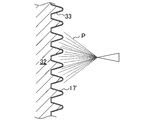
- FIG. 5 is an explanatory diagram showing a process of spraying powder onto an outer mold in the manufacture of the V-ribbed belt according to the first embodiment.
- FIG. 4 is an explanatory diagram showing a process of setting an uncrosslinked rubber sheet or the like in an inner mold in the manufacture of the V-ribbed belt according to Embodiment 1.
- FIG. 6 is an explanatory diagram showing a process of positioning an inner mold in an outer mold in the manufacture of the V-ribbed belt according to the first embodiment.
- FIG. 5 is an explanatory diagram showing a process of molding a belt slab in manufacturing the V-ribbed belt according to the first embodiment.
- FIG. 1 is sectional drawing of the V-rib surface layer of the V-ribbed belt of a 1st prior art example
- (b) is sectional drawing of the V-rib surface layer of a 2nd prior art example.
- (A) is principal part sectional drawing of the V-ribbed belt which concerns on Embodiment 2
- (b) is principal part sectional drawing of the modification.
- (A) And (b) is explanatory drawing which shows the process of setting an uncrosslinked rubber sheet etc. to an internal type
- FIG. It is a figure which shows the pulley layout of the belt running test machine for a misalignment belt running sound test. It is a figure which shows the pulley layout of the belt running test machine for a sound test at the time of rotation fluctuation belt running.
- (Embodiment 1) 1 and 2 show a V-ribbed belt B (friction transmission belt) according to the first embodiment.
- the V-ribbed belt B according to the first embodiment is used, for example, in an auxiliary machine drive belt transmission provided in an engine room of an automobile.
- the V-ribbed belt B according to Embodiment 1 has, for example, a belt circumferential length of 700 to 3000 mm, a belt width of 10 to 36 mm, and a belt thickness of 4.0 to 5.0 mm.
- the V-ribbed belt B includes a V-ribbed belt body 10 configured as a triple layer of a compression rubber layer 11 on the belt inner peripheral side, an intermediate adhesive rubber layer 12 and a back rubber layer 13 on the belt outer peripheral side.
- a core wire 14 is embedded so as to form a spiral having a pitch in the belt width direction.
- the compression rubber layer 11 is provided so that a plurality of V ribs 15 hang down to the inner peripheral side of the belt.
- the plurality of V ribs 15 are each formed in a ridge having a substantially inverted triangular cross section extending in the belt length direction, and arranged in parallel in the belt width direction.
- Each V-rib 15 has, for example, a rib height of 2.0 to 3.0 mm and a width between base ends of 1.0 to 3.6 mm.
- the number of ribs is, for example, 3 to 6 (6 in FIG. 1).
- the compressed rubber layer 11 is formed of a rubber composition obtained by heating and pressurizing an uncrosslinked rubber composition in which various compounding agents are blended and kneaded with a rubber component and then crosslinking with a crosslinking agent.
- Examples of the rubber component of the rubber composition forming the compressed rubber layer 11 include ethylene- ⁇ -olefin elastomer, chloroprene rubber (CR), chlorosulfonated polyethylene rubber (CSM), hydrogenated acrylonitrile rubber (H-NBR), and the like. Can be mentioned.
- the rubber component may be composed of a single species or a blend of a plurality of species.
- the compounding agent examples include a reinforcing material such as carbon black, a vulcanization accelerator, a crosslinking agent, an antiaging agent, and a softening agent.
- a reinforcing material for example, carbon black, channel black; furnace black such as SAF, ISAF, N-339, HAF, N-351, MAF, FEF, SRF, GPF, ECF, N-234; FT, MT, etc. Thermal black; acetylene black.
- Silica is also mentioned as a reinforcing agent.
- the reinforcing agent may be composed of a single species or a plurality of species.
- the reinforcing material preferably has a blending amount of 30 to 80 parts by mass with respect to 100 parts by mass of the rubber component, from the viewpoint of achieving a good balance between wear resistance and bending resistance.
- the vulcanization accelerator examples include metal oxides such as magnesium oxide and zinc oxide (zinc white), metal carbonates, fatty acids such as stearic acid, and derivatives thereof.
- the vulcanization accelerator may be composed of a single species or a plurality of species.
- the amount of the vulcanization accelerator is, for example, 0.5 to 8 parts by mass with respect to 100 parts by mass of the rubber component.
- crosslinking agent examples include sulfur and organic peroxides.
- sulfur may be used, organic peroxide may be used, or both of them may be used in combination.
- the crosslinking agent is preferably used in an amount of 0.5 to 4.0 parts by mass with respect to 100 parts by mass of the rubber component, and in the case of an organic peroxide, the compounding amount with respect to 100 parts by mass of the rubber component is, for example, 0. .5 to 8 parts by mass.
- Antiaging agents include amine-based, quinoline-based, hydroquinone derivatives, phenol-based and phosphite-based agents.
- the anti-aging agent may be composed of a single species or a plurality of species.
- the anti-aging agent is, for example, 0 to 8 parts by mass with respect to 100 parts by mass of the rubber component.
- the softener examples include petroleum softeners, mineral oil softeners such as paraffin wax, castor oil, cottonseed oil, sesame oil, rapeseed oil, soybean oil, palm oil, palm oil, fallen raw oil, waxy wax, rosin And vegetable oil-based softeners such as pine oil.
- the softener may be composed of a single species or a plurality of species.
- the amount of the softener other than the petroleum-based softener is, for example, 2 to 30 parts by mass with respect to 100 parts by mass of the rubber component.
- layered silicates such as a smectite group, a vermulite group, a kaolin group, may be contained.
- the compressed rubber layer 11 may be composed of a single type of rubber composition, or may be composed of a plurality of types of rubber compositions laminated together.
- the compressed rubber layer 11 may have a pulley contact side surface layer 11a in which a friction coefficient reducing material is blended and an internal rubber layer 11b laminated on the inside thereof.
- the friction coefficient reducing material include short fibers such as nylon short fibers, vinylon short fibers, aramid short fibers, polyester short fibers, cotton short fibers, and ultrahigh molecular weight polyethylene resins.
- the internal rubber layer 11b does not contain a short fiber or a friction coefficient reducing material.
- thermoplastic resin film 16 The thickness of the thermoplastic resin film 16 is preferably 0.1 to 200 ⁇ m, more preferably 1.0 to 100 ⁇ m, and even more preferably 10 to 50 ⁇ m.
- thermoplastic resin that forms the thermoplastic resin film 16 examples include polyolefin resins such as polyethylene resin (PE) and polypropylene resin (PP), polystyrene resin (PS), polycarbonate resin (PC), acrylonitrile butadiene styrene resin ( ABS) and the like.
- polyolefin resins such as polyethylene resin (PE) and polypropylene resin (PP) are preferable, and polyethylene resin (PE) is more preferable.
- the thermoplastic resin may be composed of a single species, or may be composed of a mixture of a plurality of species.
- the thermoplastic resin forming the thermoplastic resin film 16 may be a crystalline resin such as polyethylene resin (PE) or polypropylene resin (PP), or non-crystalline such as polystyrene resin (PS). Resin may be used.
- the softening temperature or melting point of the thermoplastic resin forming the thermoplastic resin film 16 is preferably 100 to 170 ° C., more preferably 130 to 160 ° C. from the viewpoint of the balance between moldability and heat resistance. .
- thermoplastic resin film 16 On the surface side of the thermoplastic resin film 16, there is provided a powder layer 17 using friction coefficient reducing powders 17a, 17b, 17c.
- the powder layer 17 may be provided so as to cover the entire surface of the thermoplastic resin film 16, and, for example, only the surface of the thermoplastic resin film 16 corresponding to a half circumference of the belt, or the inner side or the outer side in the belt width direction. It may be provided so as to partially cover the surface of the thermoplastic resin film 16 such as only the surface of the thermoplastic resin film 16.
- the powder layer 17 may be provided uniformly on the surface side of the thermoplastic resin film 16, and is provided nonuniformly so as to form, for example, a spotted pattern on the surface side of the thermoplastic resin film 16. Also good.
- the powder layer 17 includes a friction coefficient reducing powder 17 a embedded in the thermoplastic resin film 16, and a friction coefficient reducing powder 17 b supported on the surface of the thermoplastic resin film 16 and exposed to the surface. , And a friction coefficient reducing powder 17c that adheres to the friction coefficient reducing powder 17b that is aggregated and carried on the surface of the thermoplastic resin film 16 and exposed. Fine irregularities are formed on the surface of the V rib 15 by the friction coefficient reducing powders 17 b and 17 c of the powder layer 17.
- the particle size of the friction coefficient reducing powders 17a, 17b, and 17c is preferably 0.1 to 150 ⁇ m, more preferably 0.5 to 60 ⁇ m, and even more preferably 5 to 20 ⁇ m.
- the particle size is expressed by the sieve opening of the test sieve measured by the sieving method, expressed by the Stokes equivalent diameter by the sedimentation method, the equivalent sphere diameter by the light scattering method, and the electrical resistance test method.
- the particle equivalent value is expressed by the sieve opening of the test sieve measured by the sieving method, expressed by the Stokes equivalent diameter by the sedimentation method, the equivalent sphere diameter by the light scattering method, and the electrical resistance test method.
- Examples of the material for forming the friction coefficient reducing powders 17a, 17b, and 17c include fluororesin, layered silicate, talc, calcium carbonate, and silica. Of these, fluororesin is preferred from the viewpoint of reducing the friction coefficient of the surface of the V rib 15 which is the pulley contact side surface.
- the friction coefficient reducing powders 17a, 17b, and 17c may be configured of a single type, or may be configured by mixing a plurality of types.
- fluororesin examples include polytetrafluoroethylene resin (PTFE), tetrafluoroethylene / perfluoroalkyl vinyl ether copolymer resin (PFA), tetrafluoroethylene / hexafluoropropylene copolymer resin (FEP), and tetrafluoroethylene.
- PTFE polytetrafluoroethylene resin
- PFA perfluoroalkyl vinyl ether copolymer resin
- FEP tetrafluoroethylene / hexafluoropropylene copolymer resin
- ECTFE chlorotrifluoroethylene-ethylene copolymer resin
- polytetrafluoroethylene resin (PTFE) is preferred. Specific examples include PTFE powder TFW series (TFW-500, TFW-1000, TFW-2000, TFW-3000, TFW-3000F) manufactured by Seishin Enterprise Co., Ltd.
- Examples of layered silicates include smectites, vermulites, and kaolins.
- Examples of the smectite group include montmorillonite, beidellite, saponite, and hectorite.
- Examples of the vermulite family include 3 octahedral vermulites, 2 octahedral vermulites, and the like.
- Examples of the kaolin family include kaolinite, dickite, halloysite, lizardite, amesite, and chrysotile. Of these, smectite montmorillonite is preferred.
- short fibers may be in close contact with the surface of the thermoplastic resin film 16 in addition to the powder layer 17.
- short fibers include nylon short fibers, vinylon short fibers, aramid short fibers, polyester short fibers, and cotton short fibers.
- the short fibers have, for example, a length of 0.2 to 5.0 mm and a fiber diameter of 10 to 50 ⁇ m.
- the adhesive rubber layer 12 is formed in a band shape having a horizontally long cross section, and has a thickness of, for example, 1.0 to 2.5 mm.
- the back rubber layer 13 is also formed in a band shape having a horizontally long cross section, and has a thickness of, for example, 0.4 to 0.8 mm.
- the surface of the back rubber layer 13 is preferably formed in a form in which the texture of the woven fabric is transferred from the viewpoint of suppressing the sound generated between the back rubber layer 13 and the flat pulley in contact with the belt back surface.
- the adhesive rubber layer 12 and the back rubber layer 13 are formed of a rubber composition obtained by heating and pressurizing an uncrosslinked rubber composition in which various compounding agents are blended into a rubber component and then kneading and crosslinking with a crosslinking agent. .
- the back rubber layer 13 is preferably formed of a rubber composition that is slightly harder than the adhesive rubber layer 12 from the viewpoint of suppressing the occurrence of adhesion due to contact with the flat pulley with which the belt back contacts.
- the compressed rubber layer 11 and the adhesive rubber layer 12 constitute a V-ribbed belt main body 10 and, instead of the back rubber layer 13, for example, a woven fabric formed of yarns such as cotton, polyamide fiber, polyester fiber, and aramid fiber. Further, a configuration in which a reinforcing fabric composed of a knitted fabric, a nonwoven fabric or the like is provided may be used.
- Examples of the rubber component of the rubber composition forming the adhesive rubber layer 12 and the back rubber layer 13 include ethylene- ⁇ -olefin elastomer, chloroprene rubber (CR), chlorosulfonated polyethylene rubber (CSM), hydrogenated acrylonitrile rubber ( H-NBR) and the like.
- the rubber component of the adhesive rubber layer 12 and the back rubber layer 13 is preferably the same as the rubber component of the compressed rubber layer 11.
- the compounding agent examples include a reinforcing material such as carbon black, a vulcanization accelerator, a crosslinking agent, an anti-aging agent, a softening agent and the like, as in the case of the compressed rubber layer 11.
- the compressed rubber layer 11, the adhesive rubber layer 12, and the back rubber layer 13 may be formed of a rubber composition having a different composition, or may be formed of a rubber composition having the same composition.
- the core wire 14 is composed of twisted yarns such as polyester fiber (PET), polyethylene naphthalate fiber (PEN), aramid fiber, vinylon fiber and the like.
- PET polyester fiber
- PEN polyethylene naphthalate fiber
- aramid fiber vinylon fiber and the like.
- the core wire 14 is immersed in a resorcin / formalin / latex aqueous solution (hereinafter referred to as “RFL aqueous solution”) and then heated and / or rubber glue before molding. Adhesion treatment is performed to dry after dipping in the substrate.
- RTL aqueous solution resorcin / formalin / latex aqueous solution
- FIG. 5 shows a pulley layout of the auxiliary drive belt transmission device 20 for an automobile using the V-ribbed belt B according to the first embodiment.
- the accessory drive belt transmission device 20 is of a serpentine drive type in which a V-ribbed belt B is wound around six pulleys of four rib pulleys and two flat pulleys to transmit power.
- the accessory drive belt transmission 20 includes a power steering pulley 21 at the uppermost position, an AC generator pulley 22 that is disposed slightly diagonally to the right of the power steering pulley 21, an obliquely lower left of the power steering pulley 21, and an AC generator pulley.
- a flat pulley tensioner pulley 23 disposed diagonally to the left of the AC generator pulley 22
- a flat pulley water pump pulley 24 disposed diagonally to the left of the AC generator pulley 22 and directly below the tensioner pulley 23, the tensioner pulley 23, and
- a crankshaft pulley 25 disposed diagonally to the left of the water pump pulley 24 and an air conditioner pulley 26 disposed diagonally to the left of the water pump pulley 24 and the crankshaft pulley 25 are provided.
- all except the tensioner pulley 23 and the water pump pulley 24 which are flat pulleys are rib pulleys.
- These rib pulleys and flat pulleys are made of, for example, a metal press-worked product, a casting, a resin molded product such as nylon resin, phenol resin, and the diameter of the pulley is 50 to 150 mm.
- a belt forming die 30 that is concentrically provided and includes a cylindrical inner die 31 (rubber sleeve) and an outer die 32, respectively. Is used.
- the inner mold 31 is formed of a flexible material such as rubber.
- the outer peripheral surface of the inner mold 31 is formed as a molding surface, and the outer peripheral surface of the inner mold 31 is provided with a texture-forming pattern of woven fabric.
- the outer mold 32 is formed of a rigid material such as metal.
- the inner peripheral surface of the outer mold 32 is formed as a molding surface, and V rib forming grooves 33 are provided on the inner peripheral surface of the outer mold 32 at a constant pitch in the axial direction.
- the outer mold 32 is provided with a temperature control mechanism that controls the temperature by circulating a heat medium such as water vapor or a coolant such as water.
- the belt mold 30 is provided with pressurizing means for pressurizing and expanding the inner mold 31 from the inside.
- each compound is blended with a rubber component and kneaded with a kneader such as a kneader or a Banbury mixer, and the resulting uncrosslinked rubber composition is formed into a sheet by calendar molding or the like.
- a kneader such as a kneader or a Banbury mixer
- the resulting uncrosslinked rubber composition is formed into a sheet by calendar molding or the like.
- a non-crosslinked rubber sheet 11 ′ uncrosslinked rubber composition for forming a belt
- uncrosslinked rubber sheets 12 ′ and 13 ′ for the adhesive rubber layer 12 and the back rubber layer 13 are also produced.
- an adhesion treatment in which the twisted yarn 14 ′ to be the core wire 14 is immersed in an RFL aqueous solution and heated
- an adhesion treatment in which the twisted yarn 14 ′ is immersed in rubber paste and dried by heating is performed.
- an uncrosslinked rubber sheet 13 ′ for the back rubber layer 13 and an uncrosslinked rubber sheet 12 ′ for the adhesive rubber layer 12 are wound around the outer peripheral surface of the inner mold 31 in order.
- a twisted yarn 14 'for the core wire 14 is spirally wound around the cylindrical inner mold 31, and an uncrosslinked rubber sheet 12' for the adhesive rubber layer 12 and a compressed rubber layer are further formed thereon.
- the uncrosslinked rubber sheet 11 ′ for 11 is wound in order and laminated, and finally, the thermoplastic resin sheet 16 ′ is wound and covered to form the belt-formed molded body 10 ′.
- the uncrosslinked rubber sheet 11 ′ for the compressed rubber layer 11 is different for the pulley contact surface layer 11a and the internal rubber layer 11b.
- a rubber composition is used.
- the end portion of the thermoplastic resin sheet 16 ′ wound on the uncrosslinked rubber sheet 11 ′ for the compressed rubber layer 11 may be a lap joint, or a butt joint so that there is almost no gap. May be.
- the end portions of the thermoplastic resin sheet 16 ′ are butt-jointed, it is preferable that the end portions of the thermoplastic resin sheet 16 ′ are welded and bonded by heat (thermal bonding).
- the thermoplastic resin sheet 16 ′ is contracted in the subsequent vulcanization process, and the gap between the ends is widened.
- the gap is about 10 mm or less, problems such as the generation of abnormal noise do not occur.
- thermoplastic resin sheet 16 ′ a thermoplastic resin extruded into a cylindrical film may be covered on the uncrosslinked rubber sheet 11 ′ for the compressed rubber layer 11, or the thermoplastic resin The ends of the sheet may be bonded to form a cylindrical shape, which may be covered from above the uncrosslinked rubber sheet 11 ′ for the compressed rubber layer 11.
- the bonding of the end portion of the thermoplastic resin sheet is preferably thermal bonding.
- the joint portion such as the thermoplastic resin sheet 16 ′ may be provided so as to extend in a direction orthogonal to the belt length direction of the V-ribbed belt B to be manufactured, and the direction inclined with respect to the belt length direction. You may provide so that it may extend.
- the friction coefficient reducing powder P is sprayed on the molding surface for forming the pulley contact side portion of the inner peripheral surface of the outer mold 32.
- a powder layer 17 ′ is formed on the molding surface of the outer mold 32.
- the thickness of the powder layer 17 ′ is preferably 0.1 to 200 ⁇ m, and more preferably 1.0 to 100 ⁇ m.
- the powder layer 17 preferably covers the entire surface of the thermoplastic resin film 16. In this case, it is necessary to provide the powder layer 17 ′ on the entire molding surface of the outer mold 32. Accordingly, the thickness of the powder layer 17 ′ is preferably at least equal to or larger than the particle size of the friction coefficient reducing powder P.
- the powder layer 17 includes the friction coefficient reducing powder 17a embedded in the thermoplastic resin film 16 and the friction coefficient reducing powder 17b supported on the surface of the thermoplastic resin film 16 and exposed to the surface. It is preferable that the friction coefficient-reduced powder P is provided on the molding surface in a superimposed form. From such a viewpoint, the thickness of the powder layer 17 ′ is preferably at least twice the particle size of the friction coefficient-reduced powder P, and more preferably at least three times. On the other hand, if the thickness of the powder layer 17 ′ is large, a lot of excess powder adheres, and they fall off at the beginning of traveling.
- the thickness of the powder layer 17 ′ is preferably 10 times or less, more preferably 7 times or less the particle size of the friction coefficient-reduced powder P.
- spraying of the friction coefficient reduced powder P can be performed using a general powder coating apparatus.
- the inner mold 31 is positioned in the outer mold 32 and sealed. At this time, the inside of the inner mold 31 is in a sealed state.
- thermoplastic resin film is provided so as to cover the surface of the V-rib, and a friction coefficient reducing filler and an abrasion resistance improving filler are mixed in the film.
- the rubber surface before vulcanization molding is coated with a thermoplastic resin, and further, a friction coefficient reducing filler is sprayed on the surface.
- the conventional V-ribbed belt flows while being plastically deformed.
- the friction coefficient reducing filler 17 "thermoplastic resin film 16” is buried and the V-rib 15 "
- the skin layer 16a ′′ of the thermoplastic resin film 16 ′′ is formed on the surface, and the friction reducing effect by the friction coefficient reducing filler 17 ′′ cannot be obtained as much as actually expected.
- the effect of reducing the friction coefficient is maintained for a long time from the beginning of traveling, and as a result, it is possible to continuously prevent the generation of noise due to stick-slip. Further, the uneven state of the surface of the V-rib 15 is maintained for a long period from the beginning of traveling, and as a result, it is possible to continuously prevent the occurrence of belt slip due to the hydroplaning phenomenon at the time of flooding. Can solve technical problems. This will be specifically described below.
- the powder layer 17 ′ is formed by spraying the friction coefficient-reduced powder P in advance on the molding surface of the belt mold 30. Since the plastic resin sheet 16 ′ contacts the friction coefficient-reduced powder P immediately before the V-rib shape, as a result, the friction coefficient-reduced powder P flows without causing a large flow. Both embedded in the surface and what remains on the surface.
- thermoplastic resin sheet 16 ′ is greatly reduced when the thermoplastic resin sheet 16 ′ is softened or melted.
- the friction coefficient-reduced powder P can be embedded to a low level, so that a low friction coefficient can be maintained over a long period of time even when the thermoplastic resin film 16 is worn over a long period of time. An effect can be obtained.
- the powder layer 17 ′ is formed by spraying the friction coefficient-reduced powder P in advance on the molding surface of the belt mold 30.
- the first friction coefficient reducing powder 17a embedded in the thermoplastic resin film 16 and integrated by being embedded therein is partially embedded in the surface of the thermoplastic resin film 16, supported, and integrated, and the rest
- the second friction coefficient-reducing powder 17b whose surface is exposed and the second friction coefficient-reducing powder that is not embedded in the thermoplastic resin film 16 and is agglomerated and supported on the surface of the thermoplastic resin film 16 and exposed.
- the first friction coefficient reducing powder 17a functions effectively in order to maintain the friction coefficient reducing effect over a long period of time
- the second and third friction coefficient reducing powders 17b, 17c It is presumed that this contributes to the effect of reducing the friction coefficient and the prevention of the occurrence of belt slip due to the hydroplaning phenomenon at the time of flooding by forming irregularities on the surface of the V-rib 15.
- the V-ribbed belt B according to the first embodiment for example, even when applied to a pulley on which water-based coating that increases the friction coefficient is applied, the period until the most severe water-based coating is peeled off against abnormal noise due to stick-slip. Thus, it is possible to avoid the generation of noise due to stick-slip due to an increase in the friction coefficient.
- the second and third friction coefficient-reducing powders 17b and 17c have a higher residual persistence compared to the case where the powder is sprayed on the V-rib surface after the conventional vulcanization molding, so that the friction coefficient is increased.
- the frictional surface of the soft water-based paint surface is transferred and embedded by repeated friction, so that the paint surface with a very high friction coefficient originally has a low friction coefficient. It is presumed that this is because
- the first and second friction coefficient reducing powders 17a and 17b are extremely effective in suppressing the generation of abnormal noise due to continuous stick-slip. Is.
- the third friction coefficient reducing powder 17c is an effective configuration for transferring to the pulley coating and drawing out the friction coefficient reducing effect.
- the third friction coefficient-reduced powder 17c is not embedded in the thermoplastic resin film 16, but the powder is agglomerated and fixed by pressure during vulcanization molding. It is presumed that the powder is not easily washed away with water unlike the case where powder is sprayed on the surface of the V-rib, and as a result, it can be transferred to the paint well by repeated friction with the pulley.
- the powder layer 17 provided on the surface side of the thermoplastic resin film 16 that covers the pulley contact side surface of the V-ribbed belt body 10 includes the thermoplastic resin film. 16, the friction coefficient reducing powder 17a embedded in the surface 16, the friction coefficient reducing powder 17b supported on the surface of the thermoplastic resin film 16 and exposed, and agglomerated and supported on the surface of the thermoplastic resin film 16 to be exposed.
- the belt span length is as short as 40 to 100 mm
- the friction coefficient reducing powder 17c is in close contact with the friction coefficient reducing powder 17b.
- the belt span length is the distance between the contact points of the common tangent line in a pair of pulleys around which the V-ribbed belt B is wound adjacent to each other (published by Yokendo “Practical design of new version belt transmission and precision conveyance ⁇ ⁇ belt transmission "Technical Social Meeting", page 39).
- the misalignment is quantified by the method described in pages 64 and 65 of “New Practical Design of Belt Transmission / Precision Transportation Belt Transmission Technology Society” published by Yokendo.
- FIG. 13 (Embodiment 2) 13A and 13B show a V-ribbed belt B (friction transmission belt) according to the second embodiment.
- FIG. 13 (a) shows a mode in which the compressed rubber layer 11 is composed of a single layer
- FIG. 13 (b) shows that the compressed rubber layer 11 has two layers of a pulley contact side surface layer 11a and an inner rubber layer 11b inside thereof. Each configured aspect is shown.
- the part of the same name as Embodiment 1 is shown with the same code
- the V-ribbed belt B according to the second embodiment is also used, for example, for an auxiliary machine drive belt transmission provided in an engine room of an automobile.
- thermoplastic resin film 16 In the V-ribbed belt B according to the second embodiment, a cloth 18 is embedded in the thermoplastic resin film 16.
- the cloth 18 is made of, for example, a woven fabric, a knitted fabric, or a non-woven fabric.
- the cloth 18 is preferably formed in a seamless cylindrical shape. Since the cloth 18 is molded so as to conform to the shape of the V-rib 15, it is preferable that the cloth 18 has stretchability from the viewpoint of molding processability.
- the cloth 18 may be entirely embedded in the center of the thermoplastic resin film 16, or part or all of the surface may be exposed from the surface of the thermoplastic resin film 16, and the back surface may be thermoplastic. It may be in close contact with the underlying rubber of the resin film 16.
- the cloth 18 may be either subjected to a treatment for adhesion to the thermoplastic resin film 16 or the underlying rubber, or may not be subjected to such an adhesion treatment.
- Examples of the adhesion treatment include, for example, a treatment of dipping in a silane coupling agent solution and drying, a treatment of heating after dipping in an epoxy solution or an isocyanate solution, a treatment of heating after dipping in an RFL aqueous solution, and drying after dipping in a rubber paste. Or a combination thereof.
- the thickness of the cloth 18 is preferably 0.1 to 1.0 mm, and more preferably 0.3 to 1.0 mm.
- Examples of the fiber material forming the cloth 18 include synthetic fibers such as polyethylene fiber, polypropylene fiber, polyester fiber, nylon fiber, aramid fiber, and PBO fiber, and natural fibers such as cotton and hemp.
- the uncrosslinked rubber sheet 13 ′ for the back rubber layer 13 and the adhesive rubber layer are formed on the outer peripheral surface of the inner mold 31.
- the uncrosslinked rubber sheet 12 ′ for 12 is wound in order and laminated, and the twisted yarn 14 ′ for the core wire 14 is spirally wound around the cylindrical inner mold 31 from above, and the adhesive rubber layer 12 is wound thereon.
- the uncrosslinked rubber sheet 12 ′ and the uncrosslinked rubber sheet 11 ′ for the compressed rubber layer 11 are wound and laminated in order, and further covered with a cloth 18 ′, and finally, a thermoplastic resin sheet 16 ′ is wound and covered.
- the belt-forming molded body 10 ′ may be molded.
- the cloth 18 ′ may be interposed between the uncrosslinked rubber composition 12 ′ and the thermoplastic resin 16 ′ in the belt forming molded body 10 ′.
- the thermoplastic resin sheet 16 ′ on the surface side is softened or melted and penetrates into the cloth 18 ′ on the lower layer side, thereby obtaining a configuration in which the cloth 18 is embedded in the thermoplastic resin film 16.
- the uncrosslinked rubber sheet 13 ′ for the back rubber layer 13 and the adhesive are bonded to the molding surface of the outer peripheral surface of the inner mold 31.
- the uncrosslinked rubber sheet 12 ′ for the rubber layer 12 is wound in order and laminated, and then the twisted yarn 14 ′ for the core wire 14 is spirally wound around the cylindrical inner mold 31 and the adhesive rubber layer is formed thereon.
- the uncrosslinked rubber sheet 12 ′ for 12 and the uncrosslinked rubber sheet 11 ′ for the compression rubber layer 11 are wound and laminated in order, and further, the thermoplastic resin sheet 16 ′ is wound thereon and coated, and finally the cloth 18 ′.
- the V-ribbed belt B is shown as the friction transmission belt.
- the belt is not particularly limited thereto, and may be a low-edge type V-belt or the like.
- the automobile accessory drive belt transmission device 20 is shown as the belt transmission device.
- the belt transmission device is not limited to this, and may be a belt transmission device for general industries. Good.
- V-ribbed belt V-ribbed belts of Examples 1-2 and Comparative Examples 1-3 having the following configurations were produced. Each configuration is also shown in Table 1.
- Example 1 An uncrosslinked rubber sheet for a compressed rubber layer, an adhesive rubber layer, and a back rubber layer of an EPDM composition, and a twisted yarn for a cord were prepared.
- the uncrosslinked rubber sheet for the pulley contact side surface layer of the compression rubber layer is EPDM (trade name: Nordel IP4640, ethylene content 55 mass%, propylene content 40 mass%, ethylidene norbornene (ENB, manufactured by Dow Chemical Co., Ltd.).
- Mooney viscosity 40ML 1 + 4 (125 ° C.)) as a raw rubber, and 100 parts by mass of the raw rubber, carbon black (manufactured by Showa Cabot, trade name: Showa Black IP200 carbon) 50 parts by mass, 8 parts by weight of paraffin oil (manufactured by Sun Chemical Co., Ltd., trade name: Sunflex 2280), 1.6 parts by weight of vulcanizing agent (trade name: oil sulfur by Hosoi Chemical Co., Ltd.), vulcanization accelerator (Ouchi Shinsei Chemical Co.
- the uncrosslinked rubber sheet for the inner rubber layer of the compression rubber layer uses EPDM (Dow Chemical Co., product name: Nordel IP4640) as a raw rubber, and 100 parts by mass of this raw rubber, carbon black (manufactured by Showa Cabot, product) Name: Showa Black IP200 carbon) 70 parts by mass, paraffin oil (manufactured by Nippon Sun Chemical Co., Ltd., trade name: Sunflex 2280), 8 parts by mass, vulcanizing agent (trade name: oil sulfur produced by Hosoi Chemical Co., Ltd.) 1.6 parts by mass , Vulcanization accelerator (trade name: EP-150 manufactured by Ouchi Shinsei Chemical Co., Ltd.
- vulcanization accelerator DM dibenzothiadisulfide
- TT tetramethylthiuram sulfide
- EZ zinc diethyldithiocarbamate
- vulcanization accelerator manufactured by Ouchi Shinsei Chemical Co., Ltd., trade name: MSA (N-oxydiethylene-2-ben Thiazylsulfenamide)
- vulcanization aid Kao Co., Ltd. stearic acid
- vulcanization aid Siakai Chemical Co., Ltd.
- anti-aging agent Ouchi
- a product containing 2 parts by mass of Shinsei Chemical Co., Ltd. (product name: 224) and 1 part by mass of an anti-aging agent product name: MB of Ouchi Shinsei Chemical Co., Ltd.
- an anti-aging agent product name: MB of Ouchi Shinsei Chemical Co., Ltd.
- the uncrosslinked rubber sheet for the adhesive rubber layer uses EPDM (manufactured by Dow Chemical Co., Ltd., trade name: Nordel IP4640) as a raw rubber, and carbon black (manufactured by Mitsubishi Chemical Corporation, trade name: HAF carbon) with respect to 100 parts by mass of the raw rubber.
- EPDM manufactured by Dow Chemical Co., Ltd., trade name: Nordel IP4640
- carbon black manufactured by Mitsubishi Chemical Corporation, trade name: HAF carbon
- the uncrosslinked rubber sheet for the back rubber layer uses EPDM (manufactured by Dow Chemical Co., Ltd., trade name: Nordel IP4640) as a raw rubber, and carbon black (manufactured by Mitsubishi Chemical Corporation, trade name: HAF carbon) with respect to 100 parts by mass of the raw rubber. ) 60 parts by mass, paraffin oil (Nihon Sun Chemical Co., Ltd., trade name: Sunflex 2280) 8 parts by mass, vulcanizing agent (Hosoi Chemical Co., Ltd., trade name: oil sulfur) 1.6 parts by mass, vulcanization accelerator ( 2.8 parts by mass of Ouchi Shinsei Chemical Co., Ltd.
- the twisted yarn for the core wire was a polyester fiber manufactured by Teijin Ltd. having a configuration of 1100 dtex / 2 ⁇ 3 (upper twist number: 9.5 T / 10 cm (Z), lower twist number: 2.19 T / 10 cm (S)).
- the layer rubber composition was immersed in rubber paste dissolved in toluene and then subjected to heat drying at 60 ° C. for 40 seconds in order.
- the RFL aqueous solution was prepared by adding resorcin, formalin (37% by mass) and sodium hydroxide to water and stirring, and then aging for 5 hours while adding water and stirring (resorcin (R)).
- Mole) / (Mole of formalin (F)) 0.5
- RF aqueous solution was prepared, and chlorosulfonated polyethylene rubber (CSM) latex (L) having a solid content concentration of 40% by mass was added to this RF aqueous solution.
- CSM chlorosulfonated polyethylene rubber
- a rubber sleeve (inner mold) is placed on a cylindrical drum having a smooth surface, and an uncrosslinked rubber sheet for a back rubber layer and an uncrosslinked rubber sheet for an adhesive rubber layer are wound around the rubber sleeve in order, An uncrosslinked rubber sheet for the adhesive rubber layer, an uncrosslinked rubber sheet for the inner rubber layer of the compressed rubber layer, and a pulley contact side surface of the compressed rubber layer Uncrosslinked rubber sheets for layers are wound in order and laminated, and a tubular knitted fabric (made of polyamide fiber) that has not been subjected to adhesion treatment is further coated thereon, and finally a high-density polyethylene sheet (made by Keiyo Polyethylene Co., Ltd.) A belt obtained by winding a T4005 and T4010 blended at a mass ratio of 1: 1 and sheeting them with a calender roll to a thickness of 40 ⁇ m) It was molded formed molded article for. At this time, when the high density polyethylene sheet was lap join
- a belt slab is formed by covering an outer mold provided with the powder layer on a rubber sleeve on which the belt-forming molded body is set, and then heating the outer mold and pressurizing the sealed interior of the inner mold.
- the molding temperature was 170 ° C.
- the molding pressure was 1.0 MPa
- the molding time was 30 minutes.
- the high-density polyethylene sheet contracted, and the gaps were formed between the ends.
- Example 2 A V-ribbed belt produced by the same method as in Example 1 except that the knitted fabric was not covered was designated as Example 2.
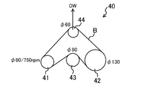
- the V rib side of the V-ribbed belt B is in contact with the drive pulley 41, the first driven pulley 42, and the third driven pulley 44 which are rib pulleys, and the second driven pulley whose back side is a flat pulley. It is comprised so that 43 may be wound in contact.
- the third driven pulley 44 is configured to be movable in the vertical direction so that belt tension can be applied to the V-ribbed belt B. Further, a misalignment of 3 ° is provided between the first driven pulley 42 and the second driven pulley 43.
- the belt running tester 40 was set, and a dead weight of 380 N was loaded on the third driven pulley 44 so as to apply the belt tension, and the atmosphere Under a temperature of 5 ° C., the drive pulley 41 was rotated at a rotational speed of 750 rpm to run the belt. Then, the belt running time until a specific abnormal noise was generated was measured and used as the sound generating running time. The test was terminated in a maximum of 300 hours.
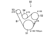
- FIG. 16 shows a pulley layout of a belt running test machine 50 for a sound test during rotation fluctuation belt running.
- Examples 1 and 2 had no abnormal noise for 300 hours.
- Comparative Example 1 produces an abnormal sound 1 hour after the start of traveling
- Comparative Examples 2 and 4 immediately after the start of traveling
- Comparative Example 3 produces an abnormal sound 25 hours after the start of traveling
- Comparative Example 8 produces an abnormal sound 8 hours after the start of traveling. Occurred.
- Examples 1 and 2 showed no abnormal noise.
- Comparative Examples 1, 3, and 5 were abnormal, and Comparative Examples 2 and 4 were loud.
Landscapes
- Engineering & Computer Science (AREA)
- General Engineering & Computer Science (AREA)
- Mechanical Engineering (AREA)
- Heating, Cooling, Or Curing Plastics Or The Like In General (AREA)
- Laminated Bodies (AREA)
Abstract
Description
図1及び2は実施形態1に係るVリブドベルトB(摩擦伝動ベルト)を示す。実施形態1に係るVリブドベルトBは、例えば、自動車のエンジンルーム内に設けられる補機駆動ベルト伝動装置等に用いられるものである。実施形態1に係るVリブドベルトBは、例えば、ベルト周長700~3000mm、ベルト幅10~36mm、及びベルト厚さ4.0~5.0mmである。
図13(a)及び(b)は実施形態2に係るVリブドベルトB(摩擦伝動ベルト)を示す。図13(a)は圧縮ゴム層11が単一層で構成された態様、及び図13(b)は圧縮ゴム層11がプーリ接触側表面層11aとその内側の内部ゴム層11bとの二層で構成された態様をそれぞれ示す。なお、実施形態1と同一名称の部分は実施形態1と同一符号で示す。実施形態2に係るVリブドベルトBもまた、例えば、自動車のエンジンルーム内に設けられる補機駆動ベルト伝動装置等に用いられるものである。
上記実施形態1及び2では、摩擦伝動ベルトとしてVリブドベルトBを示したが、特にこれに限定されるものではなく、ローエッジタイプのVベルト等であってもよい。
以下の構成の実施例1~2及び比較例1~3のVリブドベルトを作製した。それぞれの構成は表1にも示す。
EPDM組成物の圧縮ゴム層用、接着ゴム層用、及び背面ゴム層用それぞれの未架橋ゴムシート、並びに心線用の撚り糸を準備した。
編物を被せなかったことを除いて実施例1と同一の方法により製造したVリブドベルトを実施例2とした。
外型へのフッ素樹脂粉体の吹き付けを行わなかったことを除いて実施例1と同一の方法により製造したVリブドベルトを比較例1とした。
編物を被せず、且つ外型へのフッ素樹脂粉体の吹き付けを行わなかったことを除いて実施例1と同一の方法により製造したVリブドベルトを比較例2とした。
高密度ポリエチレンシートの巻き付けを行わなかったことを除いて実施例1と同一の方法により製造したVリブドベルトを比較例3とした。
編物を被せず、高密度ポリエチレンシートの巻き付けを行わず、且つ外型へのフッ素樹脂粉体の吹き付けの代わりに、加硫成型後にVリブ表面にフッ素樹脂粉体を吹き付けたことを除いて実施例1と同一の方法により製造したVリブドベルトを比較例4とした。
外型へのフッ素樹脂粉体の吹き付けの代わりに、高密度ポリエチレンシート表面にフッ素樹脂粉体を吹き付けたことを除いて実施例1と同一の方法により製造したVリブドベルトを比較例5とした。

実施例1~2及び比較例1~5のそれぞれについて以下の走行時音試験を実施した。
図15は、ミスアライメントベルト走行時音試験用のベルト走行試験機40のプーリレイアウトを示す。
図16は、回転変動ベルト走行時音試験用のベルト走行試験機50のプーリレイアウトを示す。
試験結果を表1に示す。
P 摩擦係数低減粉体
10 Vリブドベルト本体
10’ ベルト形成用成形体
16 熱可塑性樹脂膜
16’ 熱可塑性樹脂シート
17 粉体層
17a,17b,17c 摩擦係数低減粉体
18,18’ 布
20 補機駆動ベルト伝動装置
30 ベルト成形型
Claims (15)
- ゴム組成物で形成されたベルト本体がプーリに巻き掛けられて動力を伝達する摩擦伝動ベルトであって、
上記ベルト本体におけるプーリ接触側表面を被覆するように設けられた熱可塑性樹脂膜と、
上記熱可塑性樹脂膜の表面側に設けられた摩擦係数低減粉体を用いてなる粉体層と、
を備え、
上記粉体層は、上記熱可塑性樹脂膜に埋没した摩擦係数低減粉体と、該熱可塑性樹脂膜の表面に担持されて表面露出した摩擦係数低減粉体と、凝集して該熱可塑性樹脂膜の表面に担持されて露出した摩擦係数低減粉体に密着した摩擦係数低減粉体と、を含む摩擦伝動ベルト。 - 請求項1に記載された摩擦伝動ベルトにおいて、
上記熱可塑性樹脂膜には布が埋設されている摩擦伝動ベルト。 - 請求項2に記載された摩擦伝動ベルトにおいて、
上記布が編物である摩擦伝動ベルト。 - 請求項1乃至3のいずれかに記載された摩擦伝動ベルトにおいて、
上記熱可塑性樹脂膜の厚さが0.1~200μmである摩擦伝動ベルト。 - 請求項1乃至4のいずれかに記載された摩擦伝動ベルトにおいて、
上記熱可塑性樹脂膜を形成する熱可塑性樹脂の軟化温度又は融点が100~170℃である摩擦伝動ベルト。 - 請求項1乃至5のいずれかに記載された摩擦伝動ベルトにおいて、
上記熱可塑性樹脂膜がポリエチレン樹脂で形成されている摩擦伝動ベルト。 - 請求項1乃至6のいずれかに記載された摩擦伝動ベルトにおいて、
上記粉体層を構成する摩擦係数低減粉体の粒径が0.1~150μmである摩擦伝動ベルト。 - 請求項1乃至7のいずれかに記載された摩擦伝動ベルトにおいて、
上記粉体層を構成する摩擦係数低減粉体がフッ素樹脂で形成されている摩擦伝動ベルト。 - 請求項1乃至8のいずれかに記載された摩擦伝動ベルトにおいて、
上記ベルト本体がVリブドベルト本体である - ゴム組成物で形成されたベルト本体がプーリに巻き掛けられて動力を伝達する摩擦伝動ベルトであって、
ベルト成形型におけるプーリ接触側部分を形成するための成型面に、予め摩擦係数低減粉体を吹き付けて粉体層を形成し、そこに未架橋ゴム組成物を熱可塑性樹脂で被覆したベルト形成用成形体を圧接させて、該摩擦係数低減粉体が溶融せず且つ該熱可塑性樹脂が軟化乃至溶融する成型温度で該未架橋ゴム組成物を架橋させることにより製造された摩擦伝動ベルト。 - 請求項1乃至10のいずれかに記載された摩擦伝動ベルトと、該摩擦伝動ベルトのベルト本体が巻き掛けられた複数のプーリと、を備えたベルト伝動装置。
- 請求項11に記載されたベルト伝動装置において、
上記複数のプーリは、上記摩擦伝動ベルトのベルトスパン長が40~100mmである一対のプーリを含むベルト伝動装置。 - 請求項12に記載されたベルト伝動装置において、
上記一対のプーリ間のミスアライメントが0.5~2.0°であるベルト伝動装置。 - 請求項1乃至10のいずれかに記載された摩擦伝動ベルトの製造方法であって、
ベルト成形型におけるプーリ接触側部分を形成するための成型面に、予め摩擦係数低減粉体を吹き付けて粉体層を形成し、そこに未架橋ゴム組成物を熱可塑性樹脂で被覆したベルト形成用成形体を圧接させて、該摩擦係数低減粉体が溶融せず且つ該熱可塑性樹脂が軟化乃至溶融する成型温度で該未架橋ゴム組成物を架橋させる摩擦伝動ベルトの製造方法。 - 請求項14に記載された摩擦伝動ベルトの製造方法において、
上記ベルト形成用成形体における未架橋ゴム組成物と熱可塑性樹脂との間に布を介設する摩擦伝動ベルトの製造方法。
Priority Applications (8)
| Application Number | Priority Date | Filing Date | Title |
|---|---|---|---|
| BR112014016783A BR112014016783A8 (pt) | 2012-01-11 | 2012-12-25 | correia de transmissão por atrito que tem um corpo da correia feito de uma composição de borracha, e enrolada em torno de polias para transmissão de energia, sistema de transmissão da correia e método para a fabricação da correia de transmissão por atrito |
| RU2014132894A RU2608207C2 (ru) | 2012-01-11 | 2012-12-25 | Ремень фрикционной трансмиссии и способ его изготовления, а также система ременной трансмиссии |
| DE201211005638 DE112012005638T8 (de) | 2012-01-11 | 2012-12-25 | Reibungstreibriemen und Verfahren zum Herstellen desselben sowie Riementreibsystem |
| CN201280066283.9A CN104040215B (zh) | 2012-01-11 | 2012-12-25 | 摩擦传动带及其制造方法、以及带传动装置 |
| JP2013553110A JP6088985B2 (ja) | 2012-01-11 | 2012-12-25 | 摩擦伝動ベルト及びその製造方法、並びにベルト伝動装置 |
| KR1020147020649A KR101992943B1 (ko) | 2012-01-11 | 2012-12-25 | 마찰 전동 벨트 및 그 제조방법, 그리고 벨트 전동장치 |
| US14/327,436 US9951844B2 (en) | 2012-01-11 | 2014-07-09 | Friction transmission belt and method for fabricating same, and belt transmission system |
| IN6490DEN2014 IN2014DN06490A (ja) | 2012-01-11 | 2014-08-01 |
Applications Claiming Priority (2)
| Application Number | Priority Date | Filing Date | Title |
|---|---|---|---|
| JP2012002788 | 2012-01-11 | ||
| JP2012-002788 | 2012-01-11 |
Related Child Applications (1)
| Application Number | Title | Priority Date | Filing Date |
|---|---|---|---|
| US14/327,436 Continuation US9951844B2 (en) | 2012-01-11 | 2014-07-09 | Friction transmission belt and method for fabricating same, and belt transmission system |
Publications (1)
| Publication Number | Publication Date |
|---|---|
| WO2013105191A1 true WO2013105191A1 (ja) | 2013-07-18 |
Family
ID=48781170
Family Applications (1)
| Application Number | Title | Priority Date | Filing Date |
|---|---|---|---|
| PCT/JP2012/008273 WO2013105191A1 (ja) | 2012-01-11 | 2012-12-25 | 摩擦伝動ベルト及びその製造方法、並びにベルト伝動装置 |
Country Status (9)
| Country | Link |
|---|---|
| US (1) | US9951844B2 (ja) |
| JP (1) | JP6088985B2 (ja) |
| KR (1) | KR101992943B1 (ja) |
| CN (1) | CN104040215B (ja) |
| BR (1) | BR112014016783A8 (ja) |
| DE (1) | DE112012005638T8 (ja) |
| IN (1) | IN2014DN06490A (ja) |
| RU (1) | RU2608207C2 (ja) |
| WO (1) | WO2013105191A1 (ja) |
Cited By (3)
| Publication number | Priority date | Publication date | Assignee | Title |
|---|---|---|---|---|
| JP2017089896A (ja) * | 2014-04-30 | 2017-05-25 | 三ツ星ベルト株式会社 | 歯付ベルト |
| US10006519B2 (en) | 2014-04-30 | 2018-06-26 | Mitsuboshi Belting Ltd. | Toothed belt |
| JP2020041693A (ja) * | 2018-09-06 | 2020-03-19 | 三ツ星ベルト株式会社 | 伝動用vベルトおよびその製造方法 |
Families Citing this family (11)
| Publication number | Priority date | Publication date | Assignee | Title |
|---|---|---|---|---|
| KR101516934B1 (ko) * | 2011-12-14 | 2015-05-04 | 반도 카가쿠 가부시키가이샤 | 마찰 전동 벨트 및 그 제조방법 |
| ITTO20120419A1 (it) * | 2012-05-09 | 2013-11-10 | Dayco Europe Srl | Cinghia poli-v comprendente uno strato di materiale termoplastico ed un tessuto a maglia immerso in uno strato elastomerico |
| KR102253575B1 (ko) * | 2014-02-12 | 2021-05-18 | 반도 카가쿠 가부시키가이샤 | 전동벨트의 제조방법 및 전동벨트 |
| CN107532680B (zh) * | 2015-04-24 | 2022-03-11 | 阪东化学株式会社 | 传动带 |
| CN108368914B (zh) * | 2015-12-04 | 2018-12-18 | 阪东化学株式会社 | 多楔带 |
| JP6616793B2 (ja) * | 2016-04-15 | 2019-12-04 | 三ツ星ベルト株式会社 | 摩擦伝動ベルト |
| DE102016107556B3 (de) * | 2016-04-22 | 2017-05-18 | Arntz Beteiligungs Gmbh & Co. Kg | Verfahren zur Herstellung eines endlosen Treibriemens |
| DE102016209633A1 (de) * | 2016-06-02 | 2017-12-07 | Contitech Antriebssysteme Gmbh | Keilriemen und Verfahren zu seiner Herstellung |
| JP6846283B2 (ja) * | 2017-05-15 | 2021-03-24 | Nok株式会社 | 樹脂製ベルト |
| MY193858A (en) * | 2018-02-09 | 2022-10-28 | Inoova Mat Science Sdn Bhd | An elastomeric composition |
| JP6831943B1 (ja) * | 2019-10-24 | 2021-02-17 | 三ツ星ベルト株式会社 | 摩擦伝動ベルトおよびその製造方法 |
Citations (4)
| Publication number | Priority date | Publication date | Assignee | Title |
|---|---|---|---|---|
| JP2002005238A (ja) * | 2000-05-12 | 2002-01-09 | Goodyear Tire & Rubber Co:The | 動力伝達ベルト |
| JP2009036302A (ja) * | 2007-08-01 | 2009-02-19 | Bando Chem Ind Ltd | 伝動ベルト及びその製造方法 |
| JP2009533606A (ja) * | 2006-03-03 | 2009-09-17 | ハッチンソン | 伝動ベルト |
| JP2011190916A (ja) * | 2010-03-16 | 2011-09-29 | Bando Chemical Industries Ltd | 摩擦伝動ベルト及びその製造方法、並びにそれを用いたベルト伝動装置 |
Family Cites Families (17)
| Publication number | Priority date | Publication date | Assignee | Title |
|---|---|---|---|---|
| US4892510A (en) * | 1985-03-04 | 1990-01-09 | Bando Chemical Industries, Ltd. | V-ribbed belt and the method of manufacturing the same |
| DE69915387T2 (de) * | 1998-06-12 | 2005-02-24 | The Gates Corp., Denver | Flexible, thermoplastische hochtemperaturbeständige verbundwerkstoffe für die antriebsflächen eines förderbandes |
| US6443866B1 (en) * | 2000-08-14 | 2002-09-03 | The Goodyear Tire & Rubber Company | Power transmission belt |
| BR0208509B1 (pt) * | 2001-04-12 | 2011-08-09 | correia de camisa termoplástica e método para fabricar a mesma. | |
| JP4133595B2 (ja) * | 2002-08-08 | 2008-08-13 | ゲイツ・ユニッタ・アジア株式会社 | 伝動ベルト |
| ATE333057T1 (de) * | 2002-09-07 | 2006-08-15 | Contitech Antriebssysteme Gmbh | Keilrippenriemen und verfahren zu dessen herstellung |
| US7025699B2 (en) * | 2003-04-23 | 2006-04-11 | Dayco Products, Llc | Elastomer composition for power transmission belt tooth facing |
| JP2007070592A (ja) * | 2004-11-25 | 2007-03-22 | Mitsuboshi Belting Ltd | ゴム組成物、ゴム組成物の製造方法及び摩擦伝動ベルト |
| JP2007170587A (ja) * | 2005-12-26 | 2007-07-05 | Mitsuboshi Belting Ltd | Vリブドベルト |
| JP5291901B2 (ja) | 2007-07-27 | 2013-09-18 | バンドー化学株式会社 | 摩擦伝動ベルト及びそれを用いた自動車の補機駆動ベルト伝動装置 |
| KR101265821B1 (ko) * | 2008-01-25 | 2013-05-20 | 반도 카가쿠 가부시키가이샤 | 마찰전동벨트 |
| FR2936291B1 (fr) | 2008-09-23 | 2011-06-03 | Hutchinson | Courroie de transmission de puissance. |
| DE102008055497B4 (de) * | 2008-12-10 | 2020-06-18 | Contitech Antriebssysteme Gmbh | Elastischer Artikel, insbesondere Antriebsriemen, mit einer Textilauflage und einem Haftvermittler aus schmelzbarem Kunststoff |
| CN102428296B (zh) | 2009-05-20 | 2015-03-04 | 阪东化学株式会社 | 摩擦传动带及其制造方法 |
| JP5116791B2 (ja) * | 2010-03-23 | 2013-01-09 | 株式会社椿本チエイン | 歯付ベルト |
| KR101516934B1 (ko) * | 2011-12-14 | 2015-05-04 | 반도 카가쿠 가부시키가이샤 | 마찰 전동 벨트 및 그 제조방법 |
| DE102011121656A1 (de) * | 2011-12-20 | 2013-06-20 | Arntz Beteiligungs Gmbh & Co. Kg | Riemen mit mehrschichtig imprägnierter Textilauflage |
-
2012
- 2012-12-25 DE DE201211005638 patent/DE112012005638T8/de not_active Expired - Fee Related
- 2012-12-25 BR BR112014016783A patent/BR112014016783A8/pt active Search and Examination
- 2012-12-25 RU RU2014132894A patent/RU2608207C2/ru not_active IP Right Cessation
- 2012-12-25 CN CN201280066283.9A patent/CN104040215B/zh active Active
- 2012-12-25 KR KR1020147020649A patent/KR101992943B1/ko active IP Right Grant
- 2012-12-25 WO PCT/JP2012/008273 patent/WO2013105191A1/ja active Application Filing
- 2012-12-25 JP JP2013553110A patent/JP6088985B2/ja not_active Expired - Fee Related
-
2014
- 2014-07-09 US US14/327,436 patent/US9951844B2/en active Active
- 2014-08-01 IN IN6490DEN2014 patent/IN2014DN06490A/en unknown
Patent Citations (4)
| Publication number | Priority date | Publication date | Assignee | Title |
|---|---|---|---|---|
| JP2002005238A (ja) * | 2000-05-12 | 2002-01-09 | Goodyear Tire & Rubber Co:The | 動力伝達ベルト |
| JP2009533606A (ja) * | 2006-03-03 | 2009-09-17 | ハッチンソン | 伝動ベルト |
| JP2009036302A (ja) * | 2007-08-01 | 2009-02-19 | Bando Chem Ind Ltd | 伝動ベルト及びその製造方法 |
| JP2011190916A (ja) * | 2010-03-16 | 2011-09-29 | Bando Chemical Industries Ltd | 摩擦伝動ベルト及びその製造方法、並びにそれを用いたベルト伝動装置 |
Cited By (4)
| Publication number | Priority date | Publication date | Assignee | Title |
|---|---|---|---|---|
| JP2017089896A (ja) * | 2014-04-30 | 2017-05-25 | 三ツ星ベルト株式会社 | 歯付ベルト |
| US10006519B2 (en) | 2014-04-30 | 2018-06-26 | Mitsuboshi Belting Ltd. | Toothed belt |
| JP2020041693A (ja) * | 2018-09-06 | 2020-03-19 | 三ツ星ベルト株式会社 | 伝動用vベルトおよびその製造方法 |
| JP7219188B2 (ja) | 2018-09-06 | 2023-02-07 | 三ツ星ベルト株式会社 | 伝動用vベルトおよびその製造方法 |
Also Published As
| Publication number | Publication date |
|---|---|
| RU2014132894A (ru) | 2016-03-10 |
| KR20140109998A (ko) | 2014-09-16 |
| RU2608207C2 (ru) | 2017-01-17 |
| JPWO2013105191A1 (ja) | 2015-05-11 |
| DE112012005638T8 (de) | 2015-01-22 |
| US9951844B2 (en) | 2018-04-24 |
| BR112014016783A8 (pt) | 2017-07-04 |
| US20140323256A1 (en) | 2014-10-30 |
| JP6088985B2 (ja) | 2017-03-01 |
| BR112014016783A2 (pt) | 2017-06-13 |
| CN104040215B (zh) | 2016-01-20 |
| CN104040215A (zh) | 2014-09-10 |
| KR101992943B1 (ko) | 2019-06-25 |
| IN2014DN06490A (ja) | 2015-06-12 |
| DE112012005638T5 (de) | 2014-10-09 |
Similar Documents
| Publication | Publication Date | Title |
|---|---|---|
| JP6088985B2 (ja) | 摩擦伝動ベルト及びその製造方法、並びにベルト伝動装置 | |
| JP5309275B1 (ja) | 摩擦伝動ベルト及びその製造方法 | |
| JP5586282B2 (ja) | 摩擦伝動ベルト及びその製造方法、並びにそれを用いたベルト伝動装置 | |
| JP6101677B2 (ja) | 摩擦伝動ベルト | |
| JP5508648B2 (ja) | Vリブドベルト及びその製造方法 | |
| JP6412210B2 (ja) | 摩擦伝動ベルト | |
| KR101495453B1 (ko) | 마찰전동벨트 | |
| WO2017094213A1 (ja) | Vリブドベルト | |
| JP6438413B2 (ja) | 耐油性伝動ベルト | |
| JP2018076968A (ja) | 摩擦伝動ベルト | |
| US20170058995A1 (en) | Transmission belt | |
| JPWO2016194371A1 (ja) | 伝動ベルト | |
| JP6227843B1 (ja) | 伝動ベルト | |
| JP6078702B1 (ja) | Vリブドベルト | |
| JP6581892B2 (ja) | 摩擦伝動ベルト | |
| JP6903791B2 (ja) | 摩擦伝動ベルト | |
| JP2017106518A (ja) | 摩擦伝動ベルト | |
| WO2015146033A1 (ja) | 摩擦伝動ベルト |
Legal Events
| Date | Code | Title | Description |
|---|---|---|---|
| 121 | Ep: the epo has been informed by wipo that ep was designated in this application |
Ref document number: 12865417 Country of ref document: EP Kind code of ref document: A1 |
|
| ENP | Entry into the national phase |
Ref document number: 2013553110 Country of ref document: JP Kind code of ref document: A |
|
| WWE | Wipo information: entry into national phase |
Ref document number: 1120120056388 Country of ref document: DE Ref document number: 112012005638 Country of ref document: DE |
|
| ENP | Entry into the national phase |
Ref document number: 20147020649 Country of ref document: KR Kind code of ref document: A |
|
| ENP | Entry into the national phase |
Ref document number: 2014132894 Country of ref document: RU Kind code of ref document: A |
|
| REG | Reference to national code |
Ref country code: BR Ref legal event code: B01A Ref document number: 112014016783 Country of ref document: BR |
|
| 122 | Ep: pct application non-entry in european phase |
Ref document number: 12865417 Country of ref document: EP Kind code of ref document: A1 |
|
| ENP | Entry into the national phase |
Ref document number: 112014016783 Country of ref document: BR Kind code of ref document: A2 Effective date: 20140707 |