WO2013105175A1 - Dispositif de montage de composants - Google Patents
Dispositif de montage de composants Download PDFInfo
- Publication number
- WO2013105175A1 WO2013105175A1 PCT/JP2012/007891 JP2012007891W WO2013105175A1 WO 2013105175 A1 WO2013105175 A1 WO 2013105175A1 JP 2012007891 W JP2012007891 W JP 2012007891W WO 2013105175 A1 WO2013105175 A1 WO 2013105175A1
- Authority
- WO
- WIPO (PCT)
- Prior art keywords
- linear motor
- nozzle
- stator
- component mounting
- mounting apparatus
- Prior art date
Links
Images


Classifications
-
- B—PERFORMING OPERATIONS; TRANSPORTING
- B05—SPRAYING OR ATOMISING IN GENERAL; APPLYING FLUENT MATERIALS TO SURFACES, IN GENERAL
- B05B—SPRAYING APPARATUS; ATOMISING APPARATUS; NOZZLES
- B05B3/00—Spraying or sprinkling apparatus with moving outlet elements or moving deflecting elements
-
- H—ELECTRICITY
- H02—GENERATION; CONVERSION OR DISTRIBUTION OF ELECTRIC POWER
- H02K—DYNAMO-ELECTRIC MACHINES
- H02K41/00—Propulsion systems in which a rigid body is moved along a path due to dynamo-electric interaction between the body and a magnetic field travelling along the path
- H02K41/02—Linear motors; Sectional motors
- H02K41/03—Synchronous motors; Motors moving step by step; Reluctance motors
- H02K41/031—Synchronous motors; Motors moving step by step; Reluctance motors of the permanent magnet type
-
- H—ELECTRICITY
- H05—ELECTRIC TECHNIQUES NOT OTHERWISE PROVIDED FOR
- H05K—PRINTED CIRCUITS; CASINGS OR CONSTRUCTIONAL DETAILS OF ELECTRIC APPARATUS; MANUFACTURE OF ASSEMBLAGES OF ELECTRICAL COMPONENTS
- H05K13/00—Apparatus or processes specially adapted for manufacturing or adjusting assemblages of electric components
- H05K13/04—Mounting of components, e.g. of leadless components
- H05K13/0404—Pick-and-place heads or apparatus, e.g. with jaws
- H05K13/0408—Incorporating a pick-up tool
- H05K13/041—Incorporating a pick-up tool having multiple pick-up tools
-
- H—ELECTRICITY
- H05—ELECTRIC TECHNIQUES NOT OTHERWISE PROVIDED FOR
- H05K—PRINTED CIRCUITS; CASINGS OR CONSTRUCTIONAL DETAILS OF ELECTRIC APPARATUS; MANUFACTURE OF ASSEMBLAGES OF ELECTRICAL COMPONENTS
- H05K13/00—Apparatus or processes specially adapted for manufacturing or adjusting assemblages of electric components
- H05K13/04—Mounting of components, e.g. of leadless components
- H05K13/0404—Pick-and-place heads or apparatus, e.g. with jaws
- H05K13/0413—Pick-and-place heads or apparatus, e.g. with jaws with orientation of the component while holding it; Drive mechanisms for gripping tools, e.g. lifting, lowering or turning of gripping tools
-
- H—ELECTRICITY
- H02—GENERATION; CONVERSION OR DISTRIBUTION OF ELECTRIC POWER
- H02K—DYNAMO-ELECTRIC MACHINES
- H02K2201/00—Specific aspects not provided for in the other groups of this subclass relating to the magnetic circuits
- H02K2201/18—Machines moving with multiple degrees of freedom
Definitions
- the present invention relates to a component mounting apparatus that takes out a component from a component supply unit and mounts the component at a mounting position on a substrate.
- Patent Document 1 describes a component mounting apparatus in which a plurality of nozzle members are mounted on a head unit in a state where two or more nozzle members are arranged in two rows.
- each nozzle member is connected to a mover of a shaft type linear motor, and each nozzle member is driven up and down by the shaft type linear motor.
- the drive for moving the nozzle member up and down is compared to the configuration in which the nozzle member is driven up and down by a screw feed mechanism using a rotary motor as a drive source.
- the space occupied by the mechanism can be kept small, which is advantageous for narrowing the pitch of the nozzle members and reducing the size of the head unit.
- the shaft type linear motor is a so-called coreless linear motor in which the armature does not have a core
- the generated driving force propulsion force of the nozzle member
- the armature coil
- miniaturization of the head unit is hindered.
- An object of the present invention is to provide a technology that contributes to narrowing the pitch of an array of nozzle members and reducing the size of a head unit while allowing a nozzle member to be driven up and down at a higher speed in a component mounting apparatus. .
- a component mounting apparatus is a component mounting apparatus, and includes a first nozzle row including a plurality of nozzle members arranged in a row in a first direction, and a plurality arranged in a row in the first direction.
- a second nozzle row that is arranged in a second direction perpendicular to the first direction with respect to the first nozzle row, and a first linear motor that drives the nozzle member of the first nozzle row up and down,
- the linear motor main body includes a stator that is fixed to the frame member, and is opposed to the stator in the second direction and is upward and downward with respect to the stator.
- An electric machine comprising: a core having a plurality of teeth arranged in the vertical direction and extending in the second direction; and a coil mounted on each of the teeth of the core.
- the mover is a field element having a plurality of permanent magnets arranged in the vertical direction so that the surface polarities on the side facing the stator are alternately different, and the nozzle member is movable
- the first linear motor and the second linear motor are connected to a child, and the head is arranged such that the movers are close to each other in the second direction, and the stator is located outside the mover. It is mounted on the unit.
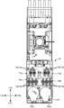
- FIG. 2 is a cross-sectional view showing the head unit (a cross-sectional view taken along the line II-II in FIG. 1). It is a bottom view which shows a head unit.
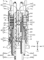
- FIG. 4 is a longitudinal sectional view (a sectional view taken along line IV-IV in FIG. 3) showing the head unit.
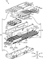
- FIG. 5 is an enlarged view of a main part of FIG. 4 showing the configuration of a front row head and a rear row head mounted on the head unit. It is a perspective view which shows the external appearance of a front row head. It is a disassembled perspective view which shows the structure of a front row head.
- FIG. 1 schematically shows a component mounting apparatus according to the present invention in a plan view.
- XYZ rectangular coordinate axes are shown in order to clarify the directional relationship.
- the component mounting apparatus includes a base 1, a substrate transport mechanism 2 that is disposed on the base 1 and transports a substrate 3 such as a printed wiring board (PWB) in the X direction, a component supply unit 4, 5, a component mounting head unit 6, a head unit driving mechanism for driving the head unit 6, an imaging unit 7 for component recognition, and the like.
- a substrate transport mechanism 2 that is disposed on the base 1 and transports a substrate 3 such as a printed wiring board (PWB) in the X direction
- PWB printed wiring board
- the substrate transport mechanism 2 includes a pair of conveyors 2 a and 2 a that transport the substrate 3 on the base 1. These conveyors 2a and 2a receive the board 3 from the right side of the figure, convey it to a predetermined mounting work position (position shown in the figure), and hold the board 3 by a holding device (not shown). Then, after the mounting operation, the conveyors 2a and 2a release the holding of the board 3, and carry out the board 3 to the left side in the figure.
- the component supply units 4 and 5 are arranged on both sides (both sides in the Y direction) of the substrate transport mechanism 2.
- a plurality of tape feeders 4 a arranged in the X direction along the substrate transport mechanism 2 are disposed in one of the component supply units 4 and 5.
- These tape feeders 4a are provided with reels around which small chip components such as ICs, transistors, capacitors, etc. are stored and wound.
- the tape feeders 4a are provided in the vicinity of the substrate transport mechanism 2 while intermittently delivering the tapes from the reels.
- a part is supplied to a predetermined part supply position.
- trays 5a and 5b are set in the component supply unit 5 on the other side at a predetermined interval in the X direction.
- Package-type parts such as QFP (Quad Flat Package) and BGA (Ball Grid Array) are arranged and placed on each tray 5a, 5b so that they can be taken out by the head unit 6 described later. ing.
- the head unit 6 takes out components from the component supply units 4 and 5 and mounts them on the substrate 3, and is disposed above the substrate transport mechanism 2 and the component supply units 4 and 5.
- the head unit 6 is movable in the X direction and the Y direction within a certain area by the head unit driving mechanism.
- the head unit driving mechanism is fixed to a pair of elevated frames 1a and 1a provided on the base 1, and extends in parallel with each other in the Y direction, and is supported by these fixed rails 9 in the X direction.
- a ball screw shaft 10 that is screwed into the unit support member 12 and driven by the Y-axis servomotor 11.
- the head unit drive mechanism is fixed to the unit support member 11 and supports the head unit 6 so as to be movable in the X direction.
- the head unit drive mechanism is screwed into the head unit 6 so as to drive the X-axis servo motor 15 as a drive source.
- the head unit driving mechanism moves the head unit 6 in the X direction via the ball screw shaft 14 by driving the X axis servo motor 15 and also moves the unit via the ball screw shaft 10 by driving the Y axis servo motor 11.
- the support member 12 is moved in the Y direction.
- the head unit driving mechanism moves the head unit 6 in the X direction and the Y direction within a certain region.
- the head unit 6 includes two front row heads 16a and 16b arranged along the X direction, and two rear row heads 16a and 16b arranged along the X direction in the same manner.
- Rear row heads 17a and 17b are provided.
- the front row heads 16a and 16b and the rear row heads 17a and 17b are units each including a multi-axis linear motor, as will be described in detail later.
- the front row heads 16a and 16b are each provided with three drive shafts 18 arranged in a row in the X direction (corresponding to the first direction of the present invention) and extending in the Z direction. Two drive shafts 18 are arranged in a row in the direction and extend in the Z direction.
- a total of ten drive shafts 18 are distributed in two rows in the front-rear direction (Y direction; corresponding to the second direction of the present invention). , And provided in a state of being distributed to four rear rows.
- the nozzle row formed by each nozzle 19 (drive shaft 18) of the front row heads 16a and 16b corresponds to the first nozzle row of the present invention
- each nozzle 19 (drive shaft 18) of the rear row heads 17a and 17b corresponds to the second nozzle row of the present invention.
- drive shafts 18 of the front row heads 16a and 16b and the drive shafts 18 of the rear row heads 17a and 17b are offset from each other in the X direction, whereby 10 nozzles 19 (drive shafts 18) as a whole are staggered. Are arranged in a shape.
- a nozzle 19 for sucking parts is attached to the tip (lower end) of each drive shaft 18.
- Each nozzle 19 can communicate with any one of a negative pressure generator, a positive pressure generator, and the atmosphere via an electric switching valve. As a result, the nozzle 19 can suck and hold the component by supplying a negative pressure to the tip of the nozzle 19 and then release the suction state of the component by supplying a positive pressure.
- the drive shaft 18 and the nozzle 19 correspond to the nozzle member of the present invention.
- Each nozzle 19 (drive shaft 18) can be moved up and down (moved in the Z direction) and rotated around the central axis (R direction) with respect to the head unit 6, and is driven by the lift drive mechanism and the rotation drive mechanism, respectively.
- the lift drive mechanism is incorporated in each of the heads 16a to 17b.
- the configuration of each of the heads 16a to 17b including the elevation drive mechanism and the configuration of the rotation drive mechanism of the nozzle 19 will be described later.
- the image pickup unit 7 picks up an image of a component taken out from the component supply units 4 and 5 before mounting in order to recognize an image of the holding state of the component by each nozzle 19.
- the component imaging unit 7 is disposed on the base 1 and at a position between the trays 5a and 5b.
- the imaging unit 7 is fixedly arranged on the base 1, and a camera (image sensor) that captures images of components held by the nozzles 19 from below and illumination for imaging the components.
- a lighting device for feeding when the head unit 6 moves above the imaging unit 7 after the components are sucked from the component supply units 4 and 5, images of the holding components of the respective nozzles 19 are imaged Data is output to a control device (not shown).
- the head unit 6 includes a total of four heads 16a to 17b including the front row heads 16a and 16b and the rear row heads 17a and 17b. As shown in FIGS. 3 and 4, among these heads 16a to 17b, the heads 16a and 17a located on the right side ( ⁇ X direction side) are adjacent to each other in the front-rear direction (Y direction). The heads 16b and 17b located on the left side are adjacent to each other in the front-rear direction. In this state, the heads 16 a to 17 b are fixed to the head frame 61 of the head unit 6.
- the configuration of the heads 16a to 17b will be described by taking the front row head 16a as an example mainly with reference to FIGS.
- the front row head 16a generally includes a multi-axis linear motor having a three-axis configuration, and the three drive shafts 18 that are individually driven up and down by the multi-axis linear motor (hereinafter simply referred to as a linear motor).
- the nozzle 19 attached to the lower end of each drive shaft 18, a return spring 20, and a linear encoder 32 are provided.
- the linear motor includes a linear motor main body 22 and a frame member 30 in which the linear motor main body 22 is incorporated.
- the linear motor main body 22 includes a stator 24, a mover 26, and a support member 28 that holds the mover 26 movably.
- the linear motor of this example (the linear motor of the front row head 16a) includes three linear motor main bodies 22, three linear encoders 32 corresponding to the respective linear motor main bodies 22, and 3 corresponding to the respective linear motor main bodies 22.
- the two return springs 20 are included, and these are incorporated in the common (one) frame member 30.
- the drive shaft 18 is connected to the mover 26 of each linear motor main body 22.
- each nozzle 19 (drive shaft 18) is driven up and down in the Z direction by the linear motor main body 22, and when the linear motor main body 22 is stopped, each urging force of the return spring 20 causes a predetermined ascending end position. It is comprised so that it may be hold
- the frame member 30 cooperates with an end block 310 whose normal direction is the Y direction, a pair of side plates 312 disposed on both sides of the end frame 310 in the X direction, and the end frame 310. It has a box-like shape penetrating in the Z direction, including a front block 314 that sandwiches both side plates 312 in the Y direction.
- These blocks 310 and 314 and the plate 312 are all made of a nonmagnetic material such as an aluminum alloy.
- Each linear motor body 22 includes a stator 24, a mover 26, and a support member 28 as described above.
- the stator 24 includes a comb-shaped core 241 integrally including a yoke extending in the Z direction and a plurality of teeth extending perpendicularly from the side portion of the yoke toward the rear side (the ⁇ Y direction side) and arranged in the Z direction.
- the armature includes a coil 242 attached to each tooth of the core 241.
- the stator 24 of each linear motor main body 22 is fixed to the front block 314 in a state of being arranged in parallel in the X direction. That is, the frame member 30 supports each stator 24.
- Reference numerals 244 in FIGS. 6 and 7 are wirings for supplying driving currents to the respective stators 24 (coils 242).
- the mover 26 is provided side by side in the Y direction with respect to the stator 24.
- the mover 26 has a facing surface that faces the stator 24 and has a rectangular cross-section extending in the Z direction, and a plurality of field elements fixed to the facing surface of the shaft-shaped member 261.
- the permanent magnet 262 and a mounting block 263 to which the drive shaft 18 is attached are provided.
- the plurality of permanent magnets 262 are fixed along the Z direction within a certain range from the upper end (+ Z direction side end) of the shaft-like member 261 so that the polarities on the surface side (that is, the stator 24 side) are alternately different. ing.
- the mounting block 263 is attached to a lower side ( ⁇ Z direction side end) of the shaft-like member 261 than a region where the permanent magnet 262 is fixed.
- the mounting block 263 is a structure that integrally includes a sleeve portion 263a having a rectangular cross section and a shaft mounting portion 263b that is connected to the lower end portion of the sleeve portion 263a.
- a stud pin 264 that protrudes forward along the Y direction is erected on the front surface of the upper end of the shaft attachment portion 263b, and one end portion of the return spring 20 is attached to the stud pin 264.
- the return spring 20 passes through the inside of the sleeve portion 263a, and the other end portion faces the sleeve 263a.
- the movers 26 of the respective linear motor main bodies 22 are arranged in parallel in the X direction, and in detail, the field elements (permanent magnets 262) face the armature (stator 24) in the Y direction.
- the predetermined gap is formed between the stator 24 and the mover 26 (more precisely, between the mover side end of the comb-shaped core 241 and the stator side surface of the permanent magnet 262).
- Each mover 26 is attached to the plurality of support members 28 fixed to the end block 310 so as to be slidable in the longitudinal direction (longitudinal direction of the shaft-like member 261; Z direction).
- each support member 28 is attached to the frame member for each linear motor main body 22, and supports each mover 26 so that it can move independently in the vertical direction.
- FIG. 7 only the support member 28 that holds the movable element 26 located on the most front side ( ⁇ X direction side) is shown, and the others are omitted.
- the other end of the return spring 20 is attached to the front block 314 with an unillustrated bolt.
- the front row head 16a further includes a shielding member 29 fixed to the frame member 30 (end block 310).
- the shielding member 29 is for preventing an adverse effect such as an interaction between the adjacent linear motor main bodies 22, for example, the movement of the movable element 26, and a shielding wall interposed between the adjacent movable elements 26. It is a U-shaped member provided, and is formed entirely from a magnetic material.
- the shaft member 261 and the support member 28 are configured by a so-called linear guide including a rail member and a slider that is movably mounted on the rail member. That is, the shaft member 261 of the movable element 26 is configured by the rail member of the guide device, and the support member 28 is configured by the slider.
- each linear motor main body 22 is configured to be able to move the mover 26 (drive shaft 18) stably and smoothly in the Z direction.
- the shaft-like member 261 (rail member) is made of a magnetic material. Accordingly, in the linear motor, the shaft-like member 261 also serves as a back yoke of a field element (permanent magnet 262). It has become. Further, as shown in FIG.
- the support members 28 of the respective linear motor main bodies 22 are arranged in a staggered manner in which the support members 28 of the adjacent linear motor main bodies 22 are vertically displaced.
- a stator 24 and a mover 26 of the linear motor main body 22 are arranged closer to each other in the X direction.
- the linear encoder 32 is for detecting the position of the mover 26 of the linear motor main body 22 in the Z direction.
- the linear encoder 32 includes a sensor substrate 321 provided with a magnetic sensor such as an MR sensor or a Hall sensor, and a plate-shaped magnetic scale 322 on which a magnetic scale readable by the magnetic sensor is recorded.
- the linear encoder 32 is provided corresponding to each linear motor main body 22.
- the front block 314 is mounted on the front block 314 in a state in which three sensor boards 321 are arranged in parallel so as to be respectively located on the lower side ( ⁇ Z direction side) of each stator 24. It is fixed.
- a flat mounting surface is formed on the front side of the mounting block 263 (sleeve portion 263a) of each mover 26, and the magnetic scale 322 is fixed to each mounting surface.
- the magnetic sensor of each sensor substrate 321 reads the corresponding magnetic scale 322, whereby the position of each mover 26 is controlled by a control device (not shown).
- the above has described the configuration of the front row head 16a located on the right side of the head unit 6, but the front row head 16b located on the left side also has the same configuration.
- the rear row heads 17a and 17b also have the same configuration as the front row head 16a except that the number of linear motor main bodies 22 is two.
- the frame member 30 of each linear motor of the front row heads 16a and 16b corresponds to the first frame member of the present invention
- the frame member of each linear motor of the rear row heads 17a and 17b is the second frame of the present invention. It corresponds to a frame member.
- the front row heads 16a and 16b and the rear row heads 17a and 17b are fixed to the head frame 61 of the head unit 6 in a state where they are arranged back to back so that the end blocks 310 of the frame member 30 are in contact with each other.
- the front row heads 16a and 16b and the rear row heads 17a and 17b are fixed to the head frame 61 in a state where the movers 26 of the linear motor main body 22 are close to each other and the stator 24 is located outside the mover 26.
- the linear motors of the heads 16a and 16b correspond to the first linear motor of the present invention
- the linear motors of the heads 17a and 17b correspond to the second linear motor of the present invention.
- the front row heads 16a and 16b and the rear row heads 17a and 17b are arranged so that the front and rear nozzles 19 (drive shafts 18) are alternately arranged in a state where the head unit 6 is viewed from the front (when viewed from the + Y direction side).
- Each linear motor main body 22 of the heads 16a and 17a and each linear motor main body 22 of the rear row heads 17a and 17b are offset in the X direction.
- a total of ten nozzles 19 (drive shafts 18) connected to each linear motor main body 22 are arranged in a staggered manner as described above.
- the rotary drive mechanism is configured as follows. That is, as shown in FIG. 4, the drive shaft 18 of each of the heads 16a to 17b is provided with the movable element 26 via a shaft holding member 181 that rotatably holds the drive shaft 18 around its central axis (R direction).
- the mounting block 263 is assembled.
- the drive shaft 18 of each head 16a to 17b can move in the Z direction and rotate around the central axis (R direction), and the intermediate portion in the longitudinal direction is a holding portion (not shown) of the head frame 61. Is held in.
- a drive belt is stretched over the pulleys in a predetermined order.
- the nozzles 19 (drive shafts 18) of the heads 16a to 17b are integrally rotated for each specific group.
- components are mounted as follows.
- the head unit 6 moves to the component supply units 4 and 5, and the components are sucked by the nozzles 19. Specifically, after the predetermined nozzle 19 is disposed, for example, above the tape feeder 4a, the drive shaft 18 is driven up and down by a linear motor, whereby the nozzle 19 is lowered and the components in the tape are adsorbed It is taken out with. At this time, if possible, the components 19 are simultaneously sucked by the plurality of nozzles 19. When the suction of the components is completed, the head unit 6 moves on the substrate 3 along the predetermined path, after passing over the component imaging unit 7.
- the suction state of the component by each nozzle 19 is image-recognized, the correction amount at the time of mounting is calculated by a control device (not shown), and the drive shaft is set so that the direction of the sucked component becomes a predetermined angle. 18 is rotated by R-axis servomotors 42a and 42b.
- the drive shaft 18 is driven up and down by the linear motor to mount the components on the substrate 3, and thereafter the head unit The remaining suction components are mounted on the substrate 3 by sequentially moving 6 to the mounting position.
- the linear motor (linear motor main body 22) that drives the nozzles 19 (drive shaft 18) up and down includes the armature (stator 24) from the core 241 and the coil 242 attached thereto. Is a so-called linear motor with a core. Therefore, a large propulsive force, that is, the raising / lowering driving force of the nozzle 19 can be obtained even with a compact configuration including a relatively small armature (stator).
- the linear motor (linear motor main body 22) has a configuration in which the stator 24 and the mover 26 are arranged in the Y direction, the occupied space in the X direction can be suppressed, and thus each head 16a to 17b.
- the nozzles 19 (drive shafts 18) can be arranged at a narrow pitch in the X direction. Furthermore, since the front row heads 16a, 16b and the rear row heads 17a, 17b are arranged so that the movers 26 of the linear motor main body 22 are close to each other and the stator 24 is located outside the mover 26, The nozzles 19 in the front row and the nozzles 19 in the rear row can be arranged at a narrow pitch in the Y direction.
- the mover 26 of the linear motor (linear motor main body 22) has a configuration in which the permanent magnet 262 is laminated on the shaft-like member 261 and is supported by the support member 28 so as to be directly movable on the frame member 30.
- the dimension from the surface of the mover 26 (surface facing the stator) to the bottom surface of the support member 28 (fixed surface with respect to the end block 310) is very small.
- the front row nozzle 19 and the back row nozzle 19 are different. They can be arranged at a narrow pitch in the Y direction.
- the nozzle 19 (drive shaft 18) can be driven up and down at a higher speed than the conventional component mounting apparatus of this type (described in Patent Document 1). Further, it is possible to effectively achieve a narrow pitch of the nozzle member arrangement and a reduction in the size of the head unit.
- the shaft-shaped member 261 is made of a magnetic material, so that the shaft-shaped member 261 also serves as a back yoke of a field element (permanent magnet 262).
- a field element permanent magnet 262
- the nozzles 19 of the front row heads 16a and 16b and the nozzles 19 of the rear row heads 17a and 17b can be arranged at a narrow pitch in the Y direction.
- the linear motor is a multi-axis linear motor, and three (or two) linear motor bodies 22 each including a stator 24, a mover 26, and a support member 28 are common to a hollow box type.
- the (one) frame member 30 is integrally assembled in a state of being arranged in parallel. That is, the stator 24 and the support member 28 of each linear motor main body 22 are fixedly supported by the common frame member 30. According to such a configuration, the space occupied by the frame member 30 can be reduced compared to a configuration in which a plurality of linear motors having independent structures are arranged in parallel, that is, a configuration in which the linear motor main bodies 22 are completely partitioned by a frame or the like. Thus, the entire linear motor is made compact in the direction in which the linear motor main bodies 22 are arranged. Therefore, the size of the head unit 6 can be reduced as the linear motor is made compact.
- the front row heads 16 a and 16 b and the rear row heads 17 a and 17 b are close to each other with the movers 26 of the linear motor main body 22, and the stator 24 is located outside the mover 26.
- the front and rear linear motors are arranged so that the stators 24 (armatures) that generate heat due to copper loss are separated from each other, so that a specific portion of the head frame 61 is thermally deformed. Is effectively prevented. Therefore, according to this component mounting apparatus, it is possible to prevent the occurrence of a drive error of the nozzle 19 (drive shaft 18) due to the thermal deformation and to perform component mounting with high accuracy.
- the component mounting apparatus described above is an exemplification of a preferred embodiment of the component mounting apparatus according to the present invention, and its specific configuration can be appropriately changed without departing from the gist of the present invention.
- the head unit 6 is incorporated into a common (one) frame member 30 with a multi-axis linear motor having a three-axis (two-axis) configuration, that is, three (two) linear motor bodies 22.
- the nozzle 19 (driving shaft 18) is driven by the linear motor thus produced.
- the nozzle 19 is driven by a single-axis linear motor, that is, a linear motor in which one linear motor body 22 is incorporated in one frame member.
- the structure which drives (drive shaft 18) may be sufficient.
- the nozzles 19 (drive shafts 18) of the front row heads 16a and 16b and the nozzles 19 (drive shafts 18) of the rear row heads 17a and 17b are offset in the X direction.
- the nozzles 19 may be arranged in the Y direction at the same position in the X direction.
- the configuration in which the nozzles 19 in the front row and the nozzles 19 in the rear row are offset in the X direction as in the embodiment, that is, the linear motor main body 22 in the front row and the linear motor main body 22 in the rear row in the X direction as described above.
- the stators 24 (armatures) of the front and rear linear motors can be separated from each other compared to the configuration in which the front and rear linear motor bodies 22 are arranged in the Y direction at the same position in the X direction. Therefore, from the viewpoint of preventing thermal deformation of the head frame 61, a configuration in which the nozzles 19 in the front row and the nozzles 19 in the rear row are offset in the X direction as in the above embodiment is advantageous.
- the shaft-like member 261 is made of a magnetic material, so that the shaft-like member 261 also serves as the back yoke of the field element (permanent magnet 262).
- a dedicated back yoke may be interposed between the shaft-shaped member 261 and the permanent magnet 262.
- each stator 24 and each support member 28 constituted by a slider are directly fixed and supported on the frame member 30, but the frame member 30 is interposed via an intermediate. It may be fixedly supported.
- a component mounting apparatus includes a first nozzle row including a plurality of nozzle members arranged in a row in a first direction, and a plurality of nozzle members arranged in a row in the first direction and the first A second nozzle row arranged in a second direction orthogonal to the first direction with respect to the nozzle row; a first linear motor that drives the nozzle member of the first nozzle row up and down; and a nozzle member of the first nozzle row.
- a head unit having a second linear motor that moves up and down, and each of the first linear motor and the second linear motor includes a linear motor main body and a frame member that supports the linear motor main body.
- the main body includes a stator that is fixed to the frame member, and a mover that is opposed to the stator in the second direction and is movable in the vertical direction with respect to the stator.
- the stator is an armature including a core having a plurality of teeth arranged in the vertical direction and extending in the second direction, and a coil attached to each of the teeth of the core
- the mover includes the fixed A field element having a plurality of permanent magnets arranged in the vertical direction so that the surface polarities on the side facing the child are alternately different, the nozzle member being connected to the mover, and the first linear
- the motor and the second linear motor are mounted on the head unit such that the movers are close to each other in the second direction, and the stator is positioned outside the mover.
- the first linear motor and the second linear motor that drive the nozzle member are so-called core-equipped linear motors in which an armature (stator) is configured by a core and a coil. Even in a compact configuration including a child (stator), a relatively large driving force, that is, a driving force of the nozzle member can be obtained.
- the first linear motor and the second linear motor have a configuration in which the mover and the stator are arranged in the second direction, it is possible to suppress the occupied space in the first direction. Therefore, it becomes possible to arrange the nozzle members in each nozzle row at a narrow pitch in the first direction.
- the nozzle members are also arranged between the nozzle rows (that is, in the second direction). It is possible to arrange them at a narrow pitch.
- the linear motor main body includes a support member that is attached to the frame member and supports the movable element so as to be movable in the vertical direction, and the movable element extends in the vertical direction to the stator. It includes a shaft-shaped member that has opposed surfaces and is movably supported by the support member, and the plurality of permanent magnets are fixed to the opposed surfaces of the shaft-shaped member.
- the dimension from the surface of the mover (surface facing the stator) to the bottom surface of the support member (fixed surface with respect to the frame member) can be further reduced.
- the nozzle members between the nozzle rows can be arranged at a narrow pitch in the second direction.
- the first linear motor is the frame member that integrally supports the plurality of linear motor bodies arranged in parallel in the first direction and the plurality of linear motor bodies.
- a first frame member, and the second linear motor integrally supports the plurality of linear motor bodies arranged in parallel in the first direction, and the plurality of linear motor bodies. It is preferable to have one second frame member which is a frame member.
- this configuration is that a plurality of linear motor frame members for driving a plurality of nozzle members are used in common for each nozzle row. According to this configuration, it is possible to reduce the size of the head unit by suppressing the space occupied by the frame member.
- the linear motor body of the first linear motor and the linear motor body of the second linear motor are offset from each other in the first direction.
- the stators can be separated from each other as compared with the configuration in which the linear motor main body of the first linear motor and the linear motor main body of the second linear motor are arranged in the second direction. This is advantageous in suppressing thermal deformation of the frame member.
- the present invention relates to a component mounting apparatus, and contributes to the narrowing of the arrangement of nozzle members and the miniaturization of the head unit while allowing the nozzle members to be driven up and down at a higher speed. Therefore, it is useful in the field of manufacturing a component mounting apparatus in which a plurality of rows of nozzle members are mounted on the head unit.
Landscapes
- Engineering & Computer Science (AREA)
- Manufacturing & Machinery (AREA)
- Microelectronics & Electronic Packaging (AREA)
- Physics & Mathematics (AREA)
- Chemical & Material Sciences (AREA)
- Combustion & Propulsion (AREA)
- Electromagnetism (AREA)
- Power Engineering (AREA)
- Supply And Installment Of Electrical Components (AREA)
- Linear Motors (AREA)
Abstract
Priority Applications (4)
| Application Number | Priority Date | Filing Date | Title |
|---|---|---|---|
| CN201280066858.7A CN104041207B (zh) | 2012-01-11 | 2012-12-11 | 元件安装装置 |
| KR1020147021377A KR101557718B1 (ko) | 2012-01-11 | 2012-12-11 | 부품 실장 장치 |
| EP12864919.1A EP2804458B1 (fr) | 2012-01-11 | 2012-12-11 | Dispositif de montage de composants |
| US14/370,621 US9370793B2 (en) | 2012-01-11 | 2012-12-11 | Component mounting device |
Applications Claiming Priority (2)
| Application Number | Priority Date | Filing Date | Title |
|---|---|---|---|
| JP2012003190A JP5873338B2 (ja) | 2012-01-11 | 2012-01-11 | 部品実装装置 |
| JP2012-003190 | 2012-01-11 |
Publications (1)
| Publication Number | Publication Date |
|---|---|
| WO2013105175A1 true WO2013105175A1 (fr) | 2013-07-18 |
Family
ID=48781154
Family Applications (1)
| Application Number | Title | Priority Date | Filing Date |
|---|---|---|---|
| PCT/JP2012/007891 WO2013105175A1 (fr) | 2012-01-11 | 2012-12-11 | Dispositif de montage de composants |
Country Status (6)
| Country | Link |
|---|---|
| US (1) | US9370793B2 (fr) |
| EP (1) | EP2804458B1 (fr) |
| JP (1) | JP5873338B2 (fr) |
| KR (1) | KR101557718B1 (fr) |
| CN (1) | CN104041207B (fr) |
| WO (1) | WO2013105175A1 (fr) |
Families Citing this family (3)
| Publication number | Priority date | Publication date | Assignee | Title |
|---|---|---|---|---|
| JP7231715B2 (ja) * | 2019-04-10 | 2023-03-01 | ヤマハ発動機株式会社 | リニア駆動装置及び部品実装用ヘッド |
| US20220117209A1 (en) * | 2020-10-16 | 2022-04-21 | Verdant Robotics, Inc. | Precision fluid delivery system |
| JP2022189465A (ja) * | 2021-06-11 | 2022-12-22 | 山洋電気株式会社 | リニアモータおよびリニアヘッドモジュール |
Citations (6)
| Publication number | Priority date | Publication date | Assignee | Title |
|---|---|---|---|---|
| JP2003046295A (ja) * | 2001-07-27 | 2003-02-14 | Fuji Mach Mfg Co Ltd | 電気部品装着システムおよび電気回路製造方法 |
| JP2006180645A (ja) * | 2004-12-24 | 2006-07-06 | Matsushita Electric Ind Co Ltd | 多軸リニアモータ、及び該多軸リニアモータを利用する実装ヘッド、部品実装装置、並びに磁力遮蔽材及び磁力遮蔽方法 |
| JP4208155B2 (ja) | 2006-03-27 | 2009-01-14 | パナソニック株式会社 | 実装ヘッド、および電子部品実装装置 |
| JP2009171660A (ja) * | 2008-01-11 | 2009-07-30 | Yamaha Motor Co Ltd | リニアモータ及び部品移載装置 |
| JP2009171683A (ja) * | 2008-01-11 | 2009-07-30 | Yamaha Motor Co Ltd | リニアモータ、該リニアモータを備えた部品実装装置、前記リニアモータを備えた部品検査装置およびリニアモータの駆動制御方法 |
| JP2010016115A (ja) * | 2008-07-02 | 2010-01-21 | Panasonic Corp | 部品実装方法 |
Family Cites Families (5)
| Publication number | Priority date | Publication date | Assignee | Title |
|---|---|---|---|---|
| JP2002239850A (ja) * | 2001-02-19 | 2002-08-28 | Murata Mfg Co Ltd | ハンドリング装置およびこのハンドリング装置を用いた部品組立装置 |
| US7043820B2 (en) | 2001-07-27 | 2006-05-16 | Fuji Machine Mfg. Co., Ltd. | Electric-component mounting system |
| JP4705118B2 (ja) * | 2008-01-11 | 2011-06-22 | ヤマハ発動機株式会社 | 多軸リニアモータ及び部品移載装置 |
| JP5253824B2 (ja) | 2008-01-11 | 2013-07-31 | ヤマハ発動機株式会社 | リニアモータ、部品実装装置及び部品検査装置 |
| JP4669021B2 (ja) * | 2008-03-28 | 2011-04-13 | ヤマハ発動機株式会社 | リニアモータユニットおよび該リニアモータユニットを備えた電子部品移載装置 |
-
2012
- 2012-01-11 JP JP2012003190A patent/JP5873338B2/ja active Active
- 2012-12-11 EP EP12864919.1A patent/EP2804458B1/fr active Active
- 2012-12-11 US US14/370,621 patent/US9370793B2/en active Active
- 2012-12-11 CN CN201280066858.7A patent/CN104041207B/zh active Active
- 2012-12-11 WO PCT/JP2012/007891 patent/WO2013105175A1/fr active Application Filing
- 2012-12-11 KR KR1020147021377A patent/KR101557718B1/ko active IP Right Grant
Patent Citations (6)
| Publication number | Priority date | Publication date | Assignee | Title |
|---|---|---|---|---|
| JP2003046295A (ja) * | 2001-07-27 | 2003-02-14 | Fuji Mach Mfg Co Ltd | 電気部品装着システムおよび電気回路製造方法 |
| JP2006180645A (ja) * | 2004-12-24 | 2006-07-06 | Matsushita Electric Ind Co Ltd | 多軸リニアモータ、及び該多軸リニアモータを利用する実装ヘッド、部品実装装置、並びに磁力遮蔽材及び磁力遮蔽方法 |
| JP4208155B2 (ja) | 2006-03-27 | 2009-01-14 | パナソニック株式会社 | 実装ヘッド、および電子部品実装装置 |
| JP2009171660A (ja) * | 2008-01-11 | 2009-07-30 | Yamaha Motor Co Ltd | リニアモータ及び部品移載装置 |
| JP2009171683A (ja) * | 2008-01-11 | 2009-07-30 | Yamaha Motor Co Ltd | リニアモータ、該リニアモータを備えた部品実装装置、前記リニアモータを備えた部品検査装置およびリニアモータの駆動制御方法 |
| JP2010016115A (ja) * | 2008-07-02 | 2010-01-21 | Panasonic Corp | 部品実装方法 |
Non-Patent Citations (1)
| Title |
|---|
| See also references of EP2804458A4 |
Also Published As
| Publication number | Publication date |
|---|---|
| US9370793B2 (en) | 2016-06-21 |
| KR20140101880A (ko) | 2014-08-20 |
| JP2013143494A (ja) | 2013-07-22 |
| EP2804458A1 (fr) | 2014-11-19 |
| EP2804458A4 (fr) | 2015-08-19 |
| CN104041207B (zh) | 2017-03-29 |
| CN104041207A (zh) | 2014-09-10 |
| JP5873338B2 (ja) | 2016-03-01 |
| US20150041557A1 (en) | 2015-02-12 |
| KR101557718B1 (ko) | 2015-10-06 |
| EP2804458B1 (fr) | 2017-08-23 |
Similar Documents
| Publication | Publication Date | Title |
|---|---|---|
| EP2234252B1 (fr) | Moteur linéaire, appareil de montage de composants et appareil d'inspection de composants | |
| WO2013105175A1 (fr) | Dispositif de montage de composants | |
| KR20100098605A (ko) | 리니어 모터 및 부품 이송 장치 | |
| KR101478694B1 (ko) | 단축 리니어 모터, 다축 리니어 모터 및 부품 이송 장치 | |
| JP5525956B2 (ja) | 実装機 | |
| WO2013105180A1 (fr) | Moteur linéaire et dispositif de montage de composant | |
| JP5475951B2 (ja) | リニアモータ及び部品移載装置 | |
| JP2005311157A (ja) | 電子部品実装用装置の直動機構 | |
| JP5000537B2 (ja) | 部品搬送装置、部品実装装置及び部品検査装置 | |
| JP5289775B2 (ja) | 部品認識装置、部品実装装置及び部品試験装置 | |
| JP2014022494A (ja) | 部品実装装置 | |
| JP5352089B2 (ja) | リニアモータ及び部品移載装置 | |
| JP5847318B2 (ja) | 光無線通信器を有する駆動装置 | |
| JP5250270B2 (ja) | リニアモータ及び部品移載装置 | |
| JPH09331198A (ja) | 電子部品実装装置 | |
| JP2009171682A (ja) | リニアモータ、部品実装装置及び部品検査装置 |
Legal Events
| Date | Code | Title | Description |
|---|---|---|---|
| 121 | Ep: the epo has been informed by wipo that ep was designated in this application |
Ref document number: 12864919 Country of ref document: EP Kind code of ref document: A1 |
|
| DPE1 | Request for preliminary examination filed after expiration of 19th month from priority date (pct application filed from 20040101) | ||
| WWE | Wipo information: entry into national phase |
Ref document number: 14370621 Country of ref document: US |
|
| REEP | Request for entry into the european phase |
Ref document number: 2012864919 Country of ref document: EP |
|
| WWE | Wipo information: entry into national phase |
Ref document number: 2012864919 Country of ref document: EP |
|
| ENP | Entry into the national phase |
Ref document number: 20147021377 Country of ref document: KR Kind code of ref document: A |
|
| NENP | Non-entry into the national phase |
Ref country code: DE |