WO2013103061A1 - 電子膨張弁および電子膨張弁を備えた空気調和機 - Google Patents
電子膨張弁および電子膨張弁を備えた空気調和機 Download PDFInfo
- Publication number
- WO2013103061A1 WO2013103061A1 PCT/JP2012/081325 JP2012081325W WO2013103061A1 WO 2013103061 A1 WO2013103061 A1 WO 2013103061A1 JP 2012081325 W JP2012081325 W JP 2012081325W WO 2013103061 A1 WO2013103061 A1 WO 2013103061A1
- Authority
- WO
- WIPO (PCT)
- Prior art keywords
- valve
- electronic expansion
- expansion valve
- opening point
- flow rate
- Prior art date
Links
- 238000004519 manufacturing process Methods 0.000 claims abstract description 12
- 239000003507 refrigerant Substances 0.000 claims description 101
- 239000012530 fluid Substances 0.000 claims description 6
- 238000004378 air conditioning Methods 0.000 abstract description 20
- 238000000034 method Methods 0.000 abstract description 17
- 239000007789 gas Substances 0.000 description 34
- 238000007689 inspection Methods 0.000 description 13
- 238000005259 measurement Methods 0.000 description 11
- 238000012937 correction Methods 0.000 description 10
- 230000002950 deficient Effects 0.000 description 7
- 238000000926 separation method Methods 0.000 description 7
- 230000000694 effects Effects 0.000 description 6
- 239000002826 coolant Substances 0.000 description 5
- 238000012986 modification Methods 0.000 description 3
- 230000004048 modification Effects 0.000 description 3
- 230000002093 peripheral effect Effects 0.000 description 3
- 230000007423 decrease Effects 0.000 description 2
- 239000006185 dispersion Substances 0.000 description 2
- 230000005284 excitation Effects 0.000 description 2
- IJGRMHOSHXDMSA-UHFFFAOYSA-N Atomic nitrogen Chemical compound N#N IJGRMHOSHXDMSA-UHFFFAOYSA-N 0.000 description 1
- 238000013459 approach Methods 0.000 description 1
- 238000006243 chemical reaction Methods 0.000 description 1
- 238000004891 communication Methods 0.000 description 1
- 230000001276 controlling effect Effects 0.000 description 1
- 230000001186 cumulative effect Effects 0.000 description 1
- 230000003247 decreasing effect Effects 0.000 description 1
- 238000013461 design Methods 0.000 description 1
- 238000010586 diagram Methods 0.000 description 1
- 229910001873 dinitrogen Inorganic materials 0.000 description 1
- 238000001595 flow curve Methods 0.000 description 1
- 239000007788 liquid Substances 0.000 description 1
- 230000001105 regulatory effect Effects 0.000 description 1
- 238000012360 testing method Methods 0.000 description 1
Images


Classifications
-
- F—MECHANICAL ENGINEERING; LIGHTING; HEATING; WEAPONS; BLASTING
- F25—REFRIGERATION OR COOLING; COMBINED HEATING AND REFRIGERATION SYSTEMS; HEAT PUMP SYSTEMS; MANUFACTURE OR STORAGE OF ICE; LIQUEFACTION SOLIDIFICATION OF GASES
- F25B—REFRIGERATION MACHINES, PLANTS OR SYSTEMS; COMBINED HEATING AND REFRIGERATION SYSTEMS; HEAT PUMP SYSTEMS
- F25B41/00—Fluid-circulation arrangements
- F25B41/30—Expansion means; Dispositions thereof
- F25B41/31—Expansion valves
- F25B41/34—Expansion valves with the valve member being actuated by electric means, e.g. by piezoelectric actuators
- F25B41/35—Expansion valves with the valve member being actuated by electric means, e.g. by piezoelectric actuators by rotary motors, e.g. by stepping motors
-
- F—MECHANICAL ENGINEERING; LIGHTING; HEATING; WEAPONS; BLASTING
- F16—ENGINEERING ELEMENTS AND UNITS; GENERAL MEASURES FOR PRODUCING AND MAINTAINING EFFECTIVE FUNCTIONING OF MACHINES OR INSTALLATIONS; THERMAL INSULATION IN GENERAL
- F16K—VALVES; TAPS; COCKS; ACTUATING-FLOATS; DEVICES FOR VENTING OR AERATING
- F16K31/00—Actuating devices; Operating means; Releasing devices
- F16K31/02—Actuating devices; Operating means; Releasing devices electric; magnetic
- F16K31/04—Actuating devices; Operating means; Releasing devices electric; magnetic using a motor
-
- F—MECHANICAL ENGINEERING; LIGHTING; HEATING; WEAPONS; BLASTING
- F16—ENGINEERING ELEMENTS AND UNITS; GENERAL MEASURES FOR PRODUCING AND MAINTAINING EFFECTIVE FUNCTIONING OF MACHINES OR INSTALLATIONS; THERMAL INSULATION IN GENERAL
- F16K—VALVES; TAPS; COCKS; ACTUATING-FLOATS; DEVICES FOR VENTING OR AERATING
- F16K37/00—Special means in or on valves or other cut-off apparatus for indicating or recording operation thereof, or for enabling an alarm to be given
- F16K37/0075—For recording or indicating the functioning of a valve in combination with test equipment
-
- F—MECHANICAL ENGINEERING; LIGHTING; HEATING; WEAPONS; BLASTING
- F25—REFRIGERATION OR COOLING; COMBINED HEATING AND REFRIGERATION SYSTEMS; HEAT PUMP SYSTEMS; MANUFACTURE OR STORAGE OF ICE; LIQUEFACTION SOLIDIFICATION OF GASES
- F25B—REFRIGERATION MACHINES, PLANTS OR SYSTEMS; COMBINED HEATING AND REFRIGERATION SYSTEMS; HEAT PUMP SYSTEMS
- F25B13/00—Compression machines, plants or systems, with reversible cycle
-
- F—MECHANICAL ENGINEERING; LIGHTING; HEATING; WEAPONS; BLASTING
- F25—REFRIGERATION OR COOLING; COMBINED HEATING AND REFRIGERATION SYSTEMS; HEAT PUMP SYSTEMS; MANUFACTURE OR STORAGE OF ICE; LIQUEFACTION SOLIDIFICATION OF GASES
- F25B—REFRIGERATION MACHINES, PLANTS OR SYSTEMS; COMBINED HEATING AND REFRIGERATION SYSTEMS; HEAT PUMP SYSTEMS
- F25B2313/00—Compression machines, plants or systems with reversible cycle not otherwise provided for
- F25B2313/031—Sensor arrangements
- F25B2313/0314—Temperature sensors near the indoor heat exchanger
-
- F—MECHANICAL ENGINEERING; LIGHTING; HEATING; WEAPONS; BLASTING
- F25—REFRIGERATION OR COOLING; COMBINED HEATING AND REFRIGERATION SYSTEMS; HEAT PUMP SYSTEMS; MANUFACTURE OR STORAGE OF ICE; LIQUEFACTION SOLIDIFICATION OF GASES
- F25B—REFRIGERATION MACHINES, PLANTS OR SYSTEMS; COMBINED HEATING AND REFRIGERATION SYSTEMS; HEAT PUMP SYSTEMS
- F25B2700/00—Sensing or detecting of parameters; Sensors therefor
- F25B2700/19—Pressures
- F25B2700/193—Pressures of the compressor
- F25B2700/1931—Discharge pressures
-
- Y—GENERAL TAGGING OF NEW TECHNOLOGICAL DEVELOPMENTS; GENERAL TAGGING OF CROSS-SECTIONAL TECHNOLOGIES SPANNING OVER SEVERAL SECTIONS OF THE IPC; TECHNICAL SUBJECTS COVERED BY FORMER USPC CROSS-REFERENCE ART COLLECTIONS [XRACs] AND DIGESTS
- Y02—TECHNOLOGIES OR APPLICATIONS FOR MITIGATION OR ADAPTATION AGAINST CLIMATE CHANGE
- Y02B—CLIMATE CHANGE MITIGATION TECHNOLOGIES RELATED TO BUILDINGS, e.g. HOUSING, HOUSE APPLIANCES OR RELATED END-USER APPLICATIONS
- Y02B30/00—Energy efficient heating, ventilation or air conditioning [HVAC]
- Y02B30/70—Efficient control or regulation technologies, e.g. for control of refrigerant flow, motor or heating
Definitions
- the present invention relates to an electronic expansion valve that is selectively opened and closed by moving a valve body with a stepping motor, and an air conditioner including the electronic expansion valve.
- the valve opening point at which the electronic expansion valve shifts from the closed state to the opened state is different for each electronic expansion valve. Such a difference is caused by variations in the mounting method of the stepping motor, the dimensions of the valve body, and the dimensions of the valve seat.
- the opening point of the electronic expansion valve mounted on the air conditioner is measured. . Specifically, the number of pulses input to the stepping motor of the electronic expansion valve is increased stepwise while detecting the temperature of the heat exchanger of the indoor unit of the air conditioner. In this process, the valve opening point is set based on the number of pulses when the heat exchanger of the indoor unit decreases by a predetermined temperature difference or more.
- This invention is made
- the objective is providing the electronic expansion valve which enables an air conditioner to perform the air-conditioning control according to the opening point of an electronic expansion valve. And it is providing the air conditioner which can perform air-conditioning control based on the valve-opening point of an electronic expansion valve.
- the valve body is movable so as to be closed, and is configured so that a distance between an inner surface of a valve hole of the valve body and a valve portion of the valve body varies when the valve body moves.
- an electronic expansion valve provided with the stepping motor, wherein the stepping motor moves the valve body in accordance with the number of pulses input to the stepping motor.
- a valve opening point is set based on the number of pulses of the stepping motor when the flow rate of the fluid flowing through the valve hole is a set value, and a pulse corresponding to the valve opening point in the manufacturing process of the electronic expansion valve
- the electronic expansion valve is given an identifier corresponding to the characteristic data of the electronic expansion valve including the measured number of pulses.
- the identifier corresponding to the characteristic data of the electronic expansion valve including the number of pulses at the valve opening point is assigned to the electronic expansion valve. Therefore, the air conditioner can perform control according to the opening point of the electronic expansion valve.
- the set value is a value equal to or greater than a maximum allowable value of a flow rate of fluid that is allowed to flow through the second refrigerant pipe when the valve hole of the valve body is closed by the valve portion. Is desirable.
- the number of pulses corresponding to the valve opening point can be easily measured.
- an air conditioner including the above-described electronic expansion valve
- the air conditioner stores an opening point of the electronic expansion valve
- the air conditioner is based on the opening point. Control the electronic expansion valve.
- the air conditioner controls the electronic expansion valve based on the valve opening point acquired in the manufacturing process. For this reason, an appropriate refrigerant flow rate is provided. Moreover, the air conditioner which can perform air-conditioning control stably is provided.
- an electronic expansion valve that enables the air conditioner to perform air conditioning control according to the opening point of the electronic expansion valve.
- the air conditioner which can perform air-conditioning control based on the valve opening point of an electronic expansion valve can be provided.
- the flowchart which shows the manufacturing method of the electronic expansion valve which concerns on embodiment of FIG.
- FIG. 1 shows the configuration of an air conditioner according to an embodiment of the present invention.
- An air conditioner 1 that performs indoor air conditioning includes a compressor 10 that compresses a refrigerant, an outdoor heat exchanger 20 that is provided outdoors, an electronic expansion valve 30 that expands the refrigerant, and an indoor heat exchanger that is provided indoors. 70, a four-way switching valve 80, and a control device 90 that controls the electronic expansion valve 30.
- the control device 90 includes a control circuit 90A and a storage device 91 that stores characteristic data of the electronic expansion valve 30.
- the storage device 91 is configured by, for example, a rewritable EEPROM (Electronically Erasable and Programmable Read Only Memory).
- a temperature sensor 81 and a pressure sensor 82 are connected to the control circuit 90A.
- the temperature sensor 81 detects the temperature of the refrigerant (hereinafter, refrigerant temperature) and outputs a refrigerant temperature signal corresponding to the refrigerant temperature to the control circuit 90A.
- the pressure sensor 82 detects the pressure of the refrigerant (hereinafter, refrigerant pressure), and outputs a refrigerant pressure signal corresponding to the refrigerant pressure to the control circuit 90A.
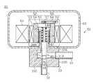
- the electronic expansion valve 30 will be described with reference to FIG.
- the electronic expansion valve 30 includes a first refrigerant pipe 31, a second refrigerant pipe 32, a valve body 33 to which the first refrigerant pipe 31 and the second refrigerant pipe 32 are connected, a rod-shaped valve body 40, and a valve body 40. And a stepping motor 50 that moves the motor along the central axis thereof.
- the valve body 33 has a columnar shape, and includes first and second surfaces 33A and 33C orthogonal to the central axis of the valve body 33 at both ends of the valve body 33, and a circumferential surface 33B.
- a guide pipe 38 extending along the central axis of the valve body 33 is provided on the first surface 33A, and the valve body 40 is movably inserted through the guide pipe 38.
- a male screw 38 ⁇ / b> A is formed on the outer peripheral surface of the guide tube 38.
- a coil spring 36 is disposed between the guide tube 38 and the valve body 40.
- the first refrigerant pipe 31 is connected to the circumferential surface 33B of the valve body 33.
- a second refrigerant pipe 32 is connected to the second surface 33 ⁇ / b> C of the valve body 33.
- a valve chamber 37 is formed inside the valve body 33.
- the first refrigerant pipe 31 is connected to the valve chamber 37 through a communication hole 31 ⁇ / b> A provided in the valve body 33.
- the second refrigerant pipe 32 is connected to the valve chamber 37 through a valve hole 34 provided in the valve main body 33.
- a taper portion whose inner diameter increases from the valve hole 34 toward the valve chamber 37 is formed at the boundary between the valve chamber 37 and the valve hole 34 on the inner surface of the valve hole 34.
- the tapered portion constitutes a valve seat 35.
- the central axis of the valve hole 34, the central axis of the guide tube 38, and the central axis of the valve body 40 coincide with each other.
- the valve body 40 is movable toward the valve hole 34 through the guide tube 38 and the valve chamber 37.
- the valve body 40 includes a main body portion 41 extending along the central axis thereof, a support rod 42 provided at one end of the main body portion 41, and a valve portion 43 provided at the other end of the main body portion 41.
- the main body portion 41 and the valve portion 43 are integrally formed.
- the main body 41 is supported relative to the support rod 42 along the central axis of the valve body 40 so as not to fall off, and is urged toward the valve hole 34 by a coil spring 36.
- the main body 41 and the support bar 42 are disposed in the guide tube 38.
- the valve portion 43 is disposed in the valve chamber 37 so as to form a variable throttle portion between the valve portion 43 and the valve seat 35. That is, when the valve body 40 moves, the distance between the inner surface of the valve hole 34 of the valve main body 33 and the valve portion 43 varies.
- the valve part 43 is formed in a truncated cone shape.
- the stepping motor 50 includes a stator 51, a rotor 52, a stopper mechanism 56 that stops the rotation of the rotor 52 at a mechanical reference position, and a case 60 that houses the stator 51, the rotor 52, and the stopper mechanism 56.
- the stator 51 is configured by an electromagnetic coil.
- the rotor 52 includes a permanent magnet 53, a rotor main body 54 that fixes the permanent magnet 53, and a fixing portion 55 to which the support rod 42 of the valve body 40 is attached.
- the valve body 33 is fixed to the case 60.
- the rotor body 54 is formed in a cylindrical shape.
- a guide tube 38 is inserted into the rotor body 54.
- a female screw 54 ⁇ / b> A that meshes with the male screw 38 ⁇ / b> A of the guide tube 38 is formed on the inner peripheral surface of the rotor body 54.
- a permanent magnet 53 is attached to the outer peripheral surface of the rotor body 54 so as to face the stator 51.
- a fixing portion 55 is attached to one end of the rotor body 54.
- One end of the coil spring 36 is in contact with the inner surface of the fixed portion 55.
- the other end of the coil spring 36 is in contact with the end surface of the main body 41 of the valve body 40.
- the stopper mechanism 56 will be described with reference to FIG.
- the stopper mechanism 56 includes a first gear 57 that is coaxial with the central axis of the support rod 42 of the valve body 40 and that can rotate integrally with the rotor 52, a second gear 58 that meshes with the first gear 57, and a second gear 58. And a stopper 59 for stopping the rotation of the motor.
- the second gear 58 has a fan shape in plan view and has an outer diameter larger than that of the first gear 57.
- the second gear 58 has end surfaces 58 ⁇ / b> A and 58 ⁇ / b> B extending along the radial direction of the second gear 58.
- the second gear 58 is rotatably supported by the case 60 by a support mechanism (not shown), and the stopper 59 is fixed to the case 60 by a fixing member (not shown).
- the stopper 59 is fixed to the case 60 by a fixing member (not shown).
- valve body 40 by driving the stepping motor 50 will be described.
- the position of the valve body 40 when the valve portion 43 contacts the valve seat 35 is referred to as a “contact position”.
- the distance between the valve portion 43 and the valve seat 35 (hereinafter, the throttle portion separation distance) is “0”.
- the label 61 on which the individual identification number 62 of the electronic expansion valve 30 and the barcode 63 are written is attached to the case 60 of the stepping motor 50.
- the individual identification number 62 is a number assigned to each electronic expansion valve 30 individually. That is, each electronic expansion valve 30 has a different individual identification number 62.
- the bar code 63 is an identifier corresponding to a measured value (hereinafter referred to as valve opening point data) of the valve opening point of the electronic expansion valve 30 to which the label 61 is attached.
- the valve opening point is set based on the number of pulses when the valve portion 43 and the valve seat 35 start to separate.
- Stepping motor 50 rotates rotor 52 based on the pulse signal output from control circuit 90A.
- the pulse signal includes a forward rotation pattern pulse signal and a reverse rotation pattern pulse signal.
- the pulse signal of the positive rotation pattern rotates the rotor 52 in the positive direction in a predetermined excitation method.
- the valve body 40 moves toward the valve hole 34 by the forward rotation of the rotor 52.
- the pulse signal of the reverse rotation pattern rotates the rotor 52 in the reverse direction in a predetermined excitation method. Due to the reverse rotation of the rotor 52, the valve body 40 moves away from the valve hole 34.
- the rotor 52 rotates positively by a rotation angle corresponding to the number of pulses included in the pulse signal. As a result, the valve body 40 moves toward the valve hole 34 by a distance corresponding to the rotation angle.
- the rotor 52 rotates reversely by a rotation angle corresponding to the number of pulses included in the pulse signal. As a result, the valve body 40 moves in a direction away from the valve hole 34 by a distance corresponding to the rotation angle.
- the number of pulses is set to an initial value of “0”. This initialization is performed, for example, when the air conditioner 1 is started.
- a value obtained by adding the number of pulses included in the pulse signal to the number of pulses corresponding to the current rotation angle position of the rotor 52 is set as a new number of pulses.
- a value obtained by subtracting the number of pulses included in the pulse signal from the number of pulses corresponding to the current rotation angle position of the rotor 52 is set as a new number of pulses. . That is, the cumulative value of the number of pulses included in the pulse signal input to the stepping motor 50 is given as the number of pulses.
- the throttle portion separation distance is substantially equal to “0”. Further, when the number of pulses is between “0” and the number of pulses corresponding to the valve opening point, the valve portion 43 is in contact with the valve seat 35, so that the throttle portion separation distance is substantially “0”. be equivalent to.
- the distance between the throttle portions increases as the number of pulses increases.
- the increment of the number of pulses and the throttle portion separation distance are substantially proportional.
- a curve G (1) shown in FIG. 6 shows the characteristics of the first electronic expansion valve 30, and a curve G (2) shows the characteristics of the second electronic expansion valve 30.
- valve closing state When the number of pulses on the horizontal axis in FIG. 6 is smaller than the number of pulses corresponding to the valve opening point, the valve portion 43 and the valve seat 35 are in contact with each other (hereinafter referred to as the valve closing state). In the valve-closed state, there is a slight gap between the valve portion 43 and the valve seat 35, so that the refrigerant slightly flows between the pipes 31 and 32. The refrigerant flow rate at this time is substantially constant regardless of the number of pulses. On the other hand, when the number of pulses becomes larger than the number of pulses corresponding to the valve opening point, the valve portion 43 is separated from the valve seat 35, so that the refrigerant flow rate increases in accordance with the increment of the number of pulses.
- valve opening point varies depending on the individual electronic expansion valve 30. This is due to the following reason.
- the electronic expansion valve 30 has variations in dimensions, assembly errors, and physical characteristics of parts constituting the electronic expansion valve 30. Therefore, the angle difference from the rotation angle of the rotor 52 when the valve portion 43 moves toward the valve hole 34 and contacts the valve seat 35 to the rotation angle when the rotor 52 is in the contact stop state is individual. It differs depending on the electronic expansion valve 30. For this reason, the valve opening point is different for each electronic expansion valve 30.
- Dimensional variations include the size of the valve body 40, the inclination of the conical surface of the valve portion 43, the inclination of the tapered portion of the valve seat 35, and the length of the coil spring 36.
- the assembly error includes an assembly error of the first gear 57, the second gear 58, and the stopper 59, and an assembly error of the valve body 40 to the fixing portion 55.
- Variations in physical characteristics include variations in the spring constant of the coil spring 36 and variations in the torque of the stepping motor 50.
- the distance between the throttle portions is controlled by the number of pulses. That is, the flow rate of the refrigerant is controlled by increasing or decreasing the number of pulses to change the throttle portion separation distance.
- the refrigerant flow rate control is performed based on a control map indicating the relationship between the number of pulses and the refrigerant flow rate.
- the opening points of the electronic expansion valves 30 mounted in each air conditioner 1 are different from each other, when the individual electronic expansion valves 30 are controlled using the same control map, the refrigerant flow rate There will be a difference.
- the desired refrigerant flow rate is small, the refrigerant flow rates realized by the individual electronic expansion valves 30 are greatly different.
- the refrigerant flow rate of the first electronic expansion valve 30 is F (1).
- the refrigerant flow rate of the second electronic expansion valve 30 is indicated as F (2).
- the air conditioning accuracy varies depending on the individual air conditioner 1 during the period in which the air conditioner 1 is operated with a small refrigerant flow rate.
- the electronic expansion valve 30 having a valve opening point that does not belong to the range in which the control map can be properly used is mounted on the air conditioner 1, the air conditioner 1 cools air excessively. Or it will be heated. For this reason, even if feedback control by the control circuit 90A is performed, the room temperature is not stabilized near the set temperature.
- the number of pulses of the refrigerant flow rate control is corrected based on the opening point of the electronic expansion valve 30.
- an example of the correction process will be described.
- the curve G (0) in FIG. the valve opening point of the curve G (0) is set as a reference valve opening point.
- the control circuit 90A sets a target value of the refrigerant flow rate (hereinafter, target refrigerant flow rate).
- target refrigerant flow rate the number of pulses to be input to the electronic expansion valve 30 (hereinafter, command pulse number) is set.
- the optimal number of pulses for realizing the target refrigerant flow rate is set by the control map, so that the target air conditioning state can be reached in the shortest time.
- the opening point of the electronic expansion valve 30 is often different from the reference valve opening point. Even if the number is set, the actual refrigerant flow rate is different from the target refrigerant flow rate. As described above, the main cause of such deviation is due to variations in the valve opening points.
- the control circuit 90A corrects the command pulse number based on the opening point of the electronic expansion valve 30. That is, the difference between the valve opening point of the electronic expansion valve 30 mounted on the air conditioner 1 and the reference valve opening point is calculated, and this difference is used as a correction value. Then, the correction command pulse number is calculated by adding the correction value to the initial command pulse number. In the control of the electronic expansion valve 30, the number of correction command pulses is used.
- control map is given by curve G (0). It is assumed that the characteristics of the mounted electronic expansion valve 30 are given by a curve G (1).
- the curve G (1) has a valve opening point (1), and the rate of change of the refrigerant flow rate with respect to the number of pulses in the valve open state of the curve G (1) is substantially equal to the curve G (0).
- the command pulse number is indicated by “Y” according to the control map.
- the characteristics of the mounted electronic expansion valve 30 are given by the curve G (1), when the electronic expansion valve 30 is controlled with the command pulse number “Y”, the refrigerant flow rate is insufficient and matches the target refrigerant flow rate. do not do. Therefore, the correction value (valve opening point (1) ⁇ reference valve opening point) is added to the command pulse number “Y” to calculate the correction command pulse number “Yx”. According to the correction command pulse number “Yx”, the mounted electronic expansion valve 30 can bring the refrigerant flow rate closer to the target refrigerant flow rate.
- FIG. 7 shows the relationship between the number of pulses and the gas flow rate in a range where the gas flow rate is small.
- the measurement conditions do not change for a certain time. Although it is possible to measure the valve opening point during operation of the air conditioner 1, the ambient temperature of the indoor heat exchanger 70 and the ambient temperature of the outdoor heat exchanger 20 change, and such measurement conditions are satisfied. It is difficult to let For this reason, the valve opening point of the electronic expansion valve 30 is measured in the manufacturing process of the electronic expansion valve 30.
- the gas is circulated from the first refrigerant pipe 31 of the electronic expansion valve 30 to the second refrigerant pipe 32.
- the gas pressure, gas temperature, and gas flow rate of the gas flowing into the first refrigerant pipe 31 are constant during measurement.
- the number of pulses input to the stepping motor 50 is gradually increased from 0, and the gas flow rate of the gas flowing through the second refrigerant pipe 32 at each pulse number is measured.
- the electronic expansion valve 30 is in the closed state, the gas flow rate of the gas flowing through the second refrigerant pipe 32 is substantially constant regardless of the number of pulses.
- the valve part 43 and the valve seat 35 are separated from each other, the gas flow rate of the gas flowing through the second refrigerant pipe 32 increases.
- valve opening point data measured value of the valve opening point
- the gas flow rate when the electronic expansion valve 30 is in the closed state is referred to as a leakage flow rate.
- the set value is set to the same value as the maximum allowable value of the leakage flow rate.
- the maximum allowable value is the maximum value of the refrigerant leakage amount that is allowed in design in the closed electronic expansion valve 30.
- the gas flow rate is measured with a flow meter such as a flow meter.
- the gas flow rate may be calculated by conversion using a differential pressure between the first refrigerant pipe 31 and the second refrigerant pipe 32.
- the method for measuring the gas flow rate is not particularly limited.
- valve opening point data measured as described above is different from the valve opening point. However, since the maximum allowable value of the leakage flow rate can be approximated to the minimum value in the control range of the refrigerant flow rate, the gas flow rate of the gas flowing through the second refrigerant pipe 32 becomes equal to the maximum allowable value of the leakage flow rate.
- the valve opening point can be set based on the number of pulses.
- the valve opening point data is associated with the electronic expansion valve 30 related to the measurement.
- valve opening point data is converted into an integer value and barcoded in a predetermined format.
- Bar code 63 (valve opening point code) is printed on label 61.
- the label 61 is affixed to the case 60 of the electronic expansion valve 30. Thereby, the electronic expansion valve 30 and the valve opening point data are associated one-to-one.
- the valve opening point data is measured in the manufacturing process as described above. At this time, the ambient environment is maintained under substantially constant conditions, and the gas flowing through the electronic expansion valve 30 is also managed under constant conditions. For this reason, the valve opening point data of each electronic expansion valve 30 is accurately measured.
- the electronic expansion valve 30 and the valve opening point data are associated one-on-one. Therefore, the air conditioner 1 in which the electronic expansion valve 30 is mounted can use the opening point data of the electronic expansion valve 30 as a parameter for controlling the refrigerant flow rate.
- the refrigerant flow rate is set to an appropriate value as described above, so that the stability of the air conditioning control is increased. In particular, the effect becomes remarkable when the refrigerant flow rate is controlled in a range where the flow rate is small.
- step S10 the electronic expansion valve 30 is assembled from each component.
- step S20 various inspections and measurements are performed on the electronic expansion valve 30.
- leak flow inspection For example, leak flow inspection, fully open flow inspection, and intermediate opening flow inspection. Also, check the operation check and valve opening point.
- the valve opening point is measured in the same manner as described above.
- the gas flow rate (leakage flow rate) when the number of pulses is “0” is measured, and it is determined whether or not it is below the maximum allowable value.
- the electronic expansion valve 30 is regarded as a defective product.
- the gas flow rate when the number of pulses is the maximum value is measured, and it is determined whether or not it is greater than or equal to the judgment value.
- the electronic expansion valve 30 is regarded as a defective product.
- the determination value is a value set in advance.
- the gas flow rate when the number of pulses is an intermediate value is measured, and it is determined whether or not the value is within the set range.
- the electronic expansion valve 30 is regarded as a defective product.
- the setting range indicates a range between a preset upper limit value and lower limit value.
- the operation inspection it is determined whether or not the stepping motor 50 operates at a predetermined voltage.
- the electronic expansion valve 30 is regarded as a defective product. Some defective products may be reassembled and re-inspected.
- step S30 the electronic expansion valve 30 that passed the inspection in all inspections is selected. A defective item in any one of the inspections is removed as a defective product (step S40).
- step S50 the barcode 63 corresponding to the valve opening point data is printed on the label 61, and this label 61 is attached to the case 60 of the electronic expansion valve 30.
- the valve opening point data of the label 61 is stored in the storage device 91 of the air conditioner 1 in the manufacturing process of the air conditioner 1. Specifically, the information of the barcode 63 of the label 61 attached to the electronic expansion valve 30 is read by a reader, and this information is stored in the storage device 91 as valve opening point data.
- the barcode 63 (opening point code), which is an identifier corresponding to the opening point data, is given to the electronic expansion valve 30.
- the valve opening point data of the electronic expansion valve 30 can be used for the air conditioner 1. That is, it is possible to cause the air conditioner 1 to perform control according to the opening point of the electronic expansion valve 30.
- the set value of the gas flow rate when measuring the valve opening point is made equal to the maximum allowable value of the leakage flow rate.
- valve-opening point data can be acquired easily. That is, in order to accurately measure the valve opening point, it is necessary to measure an inflection point at which the rate of change in the refrigerant flow rate relative to the change in the number of pulses changes. In the above embodiment, such measurement is performed. It does not have to be.
- the air conditioner 1 of the above embodiment stores the valve opening point data of the electronic expansion valve 30 that is mounted, and controls the electronic expansion valve 30 based on the valve opening point data. For this reason, the frequency at which the refrigerant flow rate deviates from the appropriate value decreases. In addition, the number of air conditioners 1 having low air conditioning control stability can be reduced.
- the valve opening point is measured by flowing gas through the electronic expansion valve 30, but the valve opening point may be measured by the following method. For example, when light is incident from one of the first refrigerant pipe 31 and the second refrigerant pipe 32 and the amount of light leakage is detected by the other refrigerant pipe, and the amount of light leakage is equal to a predetermined amount of light.
- the valve opening point is set based on the number of pulses.
- valve opening point of the electronic expansion valve 30 a liquid may be used instead of the gas.
- valve opening point may be measured using a refrigerant actually used. In the case of using the refrigerant, the temperature difference between the first refrigerant pipe 31 and the second refrigerant pipe 32 is detected, and the valve opening point is set based on the number of pulses when the temperature difference is equal to the predetermined temperature difference. May be.
- the set value for measuring the valve opening point of the electronic expansion valve 30 is equal to the maximum allowable value of the leakage flow rate, but this set value may be larger than the maximum allowable value of the leakage flow rate. Even in this case, the effect (1) can be obtained.
- the valve opening point data of the electronic expansion valve 30 is converted into a barcode, but the characteristic data of the electronic expansion valve 30 other than the valve opening point data may be converted into a barcode and applied to the electronic expansion valve 30.
- the characteristic data other than the valve opening point data include a leakage flow rate, a full opening flow rate, an inflection point of the flow rate curve, and the like.
- the leakage flow rate is measurement data obtained by a leakage flow rate inspection.
- the fully open flow rate is measurement data obtained by the fully open flow rate inspection.
- the inflection point of the flow rate curve is set based on the number of pulses when the rate of change of the refrigerant flow rate with respect to the increase in the pulse number in the flow rate curve showing the change in the refrigerant flow rate with the increase in the pulse number.
- the valve opening point data is converted into a barcode, but the form of the identifier is not limited to this.
- the identifier may be in a form that can be read by a predetermined means when the electronic expansion valve 30 is mounted on the air conditioner 1. That is, giving the valve opening point data to the electronic expansion valve 30 includes the following aspects.
- valve opening point data In another form of giving valve opening point data, a QR code (registered trademark) may be used instead of the barcode 63. Further, the numerical value of the valve opening point data may be printed on the label 61. In this case, the numerical value of the label 61 is read by image recognition. The valve opening point data may be converted into a magnetic signal, formed into a magnetic stripe, and attached to the label 61. Valve opening point data may be recorded on the IC tag. In this case, other inspection results may be stored in the IC tag.
- QR code registered trademark
- the valve opening point data may be associated with the individual identification number 62 of the electronic expansion valve 30.
- the data is recorded in association with the individual identification number 62 and the valve opening point data using a data sheet or an electronic file.
- valve opening point data corresponding to the individual identification number 62 of the electronic expansion valve 30 is read from a data sheet or an electronic file. Even in such a method, the electronic expansion valve 30 and the valve opening point data are associated one-to-one, so that the effect (1) is obtained.
- the data including the valve opening point data and the characteristic data of the electronic expansion valve 30 other than the valve opening point data may be used as one code.
- the valve opening point data and various characteristic data other than the valve opening point data are separated by a predetermined decoding program.
- the number of pulses when the gas flow rate becomes a set value (for example, the maximum allowable value of the leakage flow rate) is stored as valve opening point data (measured value of the valve opening point).
- the definition of is not limited to this.
- the first inflection point of the flow rate curve when the number of pulses is gradually increased from “0” may be stored as valve opening point data. Also with this configuration, the effect shown in (1) above can be obtained.
- the configuration of the electronic expansion valve 30 is as follows.
- a valve body 40 having a valve portion 43 inserted into the valve hole 34 of the valve body 33, the valve body 40 being connected to the valve hole of the valve body 33 by the valve portion 43.
- 34 is movable to selectively open and close, and when the valve body 40 moves, the distance between the inner surface of the valve hole 34 of the valve body 33 and the valve portion 43 of the valve body 40
- An electronic device comprising: the valve body 40 configured to vary, and a stepping motor 50 that moves the valve body 40 in accordance with the number of pulses input to the stepping motor 50.
- the valve hole 34 A valve opening point is set based on the pulse number of the stepping motor 50 when the rate of change of the flow rate of the fluid flowing therethrough with respect to the pulse number starts to increase, and the valve opening point is set in the manufacturing process of the electronic expansion valve 30.
- the number of corresponding pulses is measured, and an identifier corresponding to the characteristic data of the electronic expansion valve 30 including the measured number of pulses is given. Also with this configuration, the effect according to the above (1) can be obtained. Note that when the rate of change of the flow rate of the fluid flowing through the valve hole 34 starts to increase, the first inflection point of the flow rate curve when the pulse number is gradually increased from “0”. Show.
Landscapes
- Engineering & Computer Science (AREA)
- General Engineering & Computer Science (AREA)
- Mechanical Engineering (AREA)
- Physics & Mathematics (AREA)
- Thermal Sciences (AREA)
- Electrically Driven Valve-Operating Means (AREA)
- Air Conditioning Control Device (AREA)
Abstract
Description
なお、本発明は上記実施形態に限られるものではなく、上記実施形態を例えば以下に示すように変更して実施することもできる。また以下の各変形例は、異なる変形例と組み合わせて実施することもできる。
Claims (3)
- 第1冷媒配管と、
第2冷媒配管と、
前記第1冷媒配管に接続された弁室、および該弁室と前記第2冷媒配管との間を接続する弁孔を有した弁本体と、
前記弁本体の弁孔に挿入される弁部を有する弁体であって、該弁体は、前記弁部によって前記弁本体の弁孔を選択的に開放および閉鎖するように移動可能であり、前記弁体が移動する際に、前記弁本体の弁孔の内面と前記弁体の弁部との間の距離が変動するように構成された前記弁体と、
ステッピングモータであって、該ステッピングモータに入力されるパルス数に応じて前記弁体を移動させる前記ステッピングモータとを備えた電子膨張弁において、
前記弁孔を通って流動する流体の流量が設定値に等しいときの前記ステッピングモータのパルス数に基づいて開弁点を設定し、
前記電子膨張弁の製造工程において前記開弁点に対応するパルス数が測定され、その測定されたパルス数を含む前記電子膨張弁の特性データに対応する識別子が付与されていることを特徴とする電子膨張弁。 - 請求項1に記載の電子膨張弁において、
前記設定値は、前記弁部によって前記弁本体の弁孔が閉鎖されている際に前記第2冷媒配管を通って流動することが許容される流体の流量の最大許容値以上の値であることを特徴とする電子膨張弁。 - 請求項1または2に記載の電子膨張弁を備えた空気調和機において、
前記電子膨張弁の開弁点を記憶し、かつ前記開弁点に基づいて前記電子膨張弁を制御することを特徴とする空気調和機。
Priority Applications (6)
| Application Number | Priority Date | Filing Date | Title |
|---|---|---|---|
| AU2012364111A AU2012364111B2 (en) | 2012-01-04 | 2012-12-04 | Electronic expansion valve and air conditioner provided with electronic expansion valve |
| US14/368,024 US9310114B2 (en) | 2012-01-04 | 2012-12-04 | Electronic expansion valve and air conditioner provided with electronic expansion valve |
| ES12864323.6T ES2573628T3 (es) | 2012-01-04 | 2012-12-04 | Válvula de expansión electrónica y acondicionador de aire provisto de válvula de expansión electrónica |
| EP12864323.6A EP2801771B1 (en) | 2012-01-04 | 2012-12-04 | Electronic expansion valve and air conditioner provided with electronic expansion valve |
| CN201280065722.4A CN104024770B (zh) | 2012-01-04 | 2012-12-04 | 电子膨胀阀和具备电子膨胀阀的空调机 |
| KR1020147018235A KR101476116B1 (ko) | 2012-01-04 | 2012-12-04 | 전자 팽창 밸브 및 전자 팽창 밸브를 구비한 공기 조화기 |
Applications Claiming Priority (2)
| Application Number | Priority Date | Filing Date | Title |
|---|---|---|---|
| JP2012000261 | 2012-01-04 | ||
| JP2012-000261 | 2012-01-04 |
Publications (1)
| Publication Number | Publication Date |
|---|---|
| WO2013103061A1 true WO2013103061A1 (ja) | 2013-07-11 |
Family
ID=48745127
Family Applications (1)
| Application Number | Title | Priority Date | Filing Date |
|---|---|---|---|
| PCT/JP2012/081325 WO2013103061A1 (ja) | 2012-01-04 | 2012-12-04 | 電子膨張弁および電子膨張弁を備えた空気調和機 |
Country Status (8)
| Country | Link |
|---|---|
| US (1) | US9310114B2 (ja) |
| EP (1) | EP2801771B1 (ja) |
| JP (1) | JP5218694B1 (ja) |
| KR (1) | KR101476116B1 (ja) |
| CN (1) | CN104024770B (ja) |
| AU (1) | AU2012364111B2 (ja) |
| ES (1) | ES2573628T3 (ja) |
| WO (1) | WO2013103061A1 (ja) |
Cited By (3)
| Publication number | Priority date | Publication date | Assignee | Title |
|---|---|---|---|---|
| US20160258660A1 (en) * | 2013-10-28 | 2016-09-08 | Gree Electric Appliances, Inc. Of Zhuhai | Electronic expansion valve |
| WO2022127265A1 (zh) * | 2020-12-14 | 2022-06-23 | 广东威灵电机制造有限公司 | 阀针组件、电子膨胀阀和制冷设备 |
| WO2022176050A1 (ja) | 2021-02-17 | 2022-08-25 | 三菱電機株式会社 | 空気調和装置 |
Families Citing this family (19)
| Publication number | Priority date | Publication date | Assignee | Title |
|---|---|---|---|---|
| US10588176B2 (en) * | 2014-02-28 | 2020-03-10 | Ayr Ltd. | Electronic vaporiser system |
| EP3147593B1 (en) * | 2015-09-22 | 2021-03-17 | Honeywell spol s.r.o. | Expansion valve for a vapor compression system |
| CN105299973B (zh) * | 2015-10-19 | 2018-04-20 | 珠海格力电器股份有限公司 | 一种电子膨胀阀的控制方法及系统 |
| ITUA201656563U1 (it) * | 2016-03-11 | 2017-09-11 | Elbi Int Spa | Dispositivo elettrovalvolare. |
| CN107284193B (zh) * | 2016-03-31 | 2022-06-14 | 杭州三花研究院有限公司 | 空调系统、该空调系统的控制系统及控制方法 |
| JP2018185104A (ja) * | 2017-04-26 | 2018-11-22 | 株式会社デンソー | 冷凍サイクル装置 |
| US10082216B1 (en) * | 2017-07-21 | 2018-09-25 | Johnson Controls Technology Company | Adaptive valve control system |
| EP3712472A4 (en) * | 2017-11-13 | 2021-08-04 | Emerson Climate Technologies (Suzhou) Co., Ltd. | ELECTRONIC EXPANSION VALVE |
| EP3671070A1 (en) | 2018-12-20 | 2020-06-24 | Danfoss A/S | Valve, in particular expansion valve |
| EP3671073A1 (en) | 2018-12-20 | 2020-06-24 | Danfoss A/S | Electric expansion valve |
| WO2021228780A1 (en) * | 2020-05-11 | 2021-11-18 | Rotiny Aps | Actuator for fluid flow controllers |
| DE102020112658B4 (de) * | 2020-05-11 | 2022-05-19 | Pierburg Gmbh | Expansionsventilanordnung für einen Kälte- oder Klimakreislauf |
| ES2943533T3 (es) * | 2020-07-20 | 2023-06-14 | Abb Schweiz Ag | Compartimento de disyuntor |
| JP7357939B2 (ja) * | 2021-03-08 | 2023-10-10 | 株式会社不二工機 | 弁本体アセンブリ、ステーターユニット、電動弁および空気調和機、ならびに、弁本体アセンブリの製造方法およびステーターユニットの製造方法 |
| CN113137716B (zh) * | 2021-03-25 | 2023-01-31 | 青岛海尔空调电子有限公司 | 用于多联机系统的膨胀阀类型识别方法及多联机 |
| CN115711318A (zh) | 2021-08-23 | 2023-02-24 | 株式会社不二工机 | 电动阀、该电动阀的控制方法及其制造方法 |
| JP7345922B2 (ja) * | 2021-08-23 | 2023-09-19 | 株式会社不二工機 | 電動弁、その制御方法、およびその製造方法 |
| JP7479714B2 (ja) * | 2022-02-14 | 2024-05-09 | 株式会社不二工機 | 電動弁制御装置および電動弁装置、ならびに、電動弁の制御方法 |
| WO2023199425A1 (ja) * | 2022-04-13 | 2023-10-19 | 三菱電機株式会社 | 冷媒漏洩検知システムおよび漏洩検知装置 |
Citations (5)
| Publication number | Priority date | Publication date | Assignee | Title |
|---|---|---|---|---|
| JPH06265222A (ja) * | 1993-03-11 | 1994-09-20 | Mitsubishi Heavy Ind Ltd | 空気調和機の膨張弁制御装置 |
| JPH0996452A (ja) * | 1995-09-29 | 1997-04-08 | Toshiba Corp | 空気調和機 |
| JP2001194029A (ja) * | 2000-01-05 | 2001-07-17 | Kubota Corp | 冷凍回路における電子膨張弁の調整方法 |
| JP2009068744A (ja) | 2007-09-12 | 2009-04-02 | Mitsubishi Heavy Ind Ltd | 電動膨張弁の開弁パルス設定方法およびマルチ形空気調和機 |
| JP2011255330A (ja) * | 2010-06-10 | 2011-12-22 | Hitachi Koki Co Ltd | 遠心分離機 |
Family Cites Families (11)
| Publication number | Priority date | Publication date | Assignee | Title |
|---|---|---|---|---|
| JPH05256544A (ja) | 1992-03-12 | 1993-10-05 | Toshiba Corp | 冷凍機の電子膨脹弁制御装置 |
| US5675982A (en) * | 1996-04-26 | 1997-10-14 | Rocky Research | Pulsed operation control valve |
| CN2314309Y (zh) * | 1997-12-24 | 1999-04-14 | 泰州市电器厂 | 家用空调用电子膨胀阀 |
| DE19846226C2 (de) * | 1998-10-07 | 2002-07-11 | Emerson Electric Gmbh | Ventilanordnung |
| JP3937029B2 (ja) | 1999-03-26 | 2007-06-27 | 株式会社鷺宮製作所 | 電動弁 |
| CN1120962C (zh) * | 2000-06-07 | 2003-09-10 | 三星电子株式会社 | 用于空调启动的控制系统和控制方法 |
| JP2005024152A (ja) * | 2003-07-01 | 2005-01-27 | Matsushita Electric Ind Co Ltd | マルチ式空気調和機の膨張弁制御方法 |
| CN2703169Y (zh) | 2004-06-02 | 2005-06-01 | 浙江盾安精工集团有限公司 | 变频空调用减速式电子膨胀阀 |
| CN2786597Y (zh) | 2005-04-14 | 2006-06-07 | 珠海格力电器股份有限公司 | 空调室外机的测试机及测试系统 |
| JP5022120B2 (ja) | 2007-07-03 | 2012-09-12 | 株式会社不二工機 | 冷暖房システム用の電動弁 |
| JP4329858B2 (ja) * | 2007-11-30 | 2009-09-09 | ダイキン工業株式会社 | 冷凍装置 |
-
2012
- 2012-12-03 JP JP2012264162A patent/JP5218694B1/ja active Active
- 2012-12-04 US US14/368,024 patent/US9310114B2/en active Active
- 2012-12-04 WO PCT/JP2012/081325 patent/WO2013103061A1/ja active Application Filing
- 2012-12-04 EP EP12864323.6A patent/EP2801771B1/en active Active
- 2012-12-04 KR KR1020147018235A patent/KR101476116B1/ko active IP Right Grant
- 2012-12-04 CN CN201280065722.4A patent/CN104024770B/zh active Active
- 2012-12-04 ES ES12864323.6T patent/ES2573628T3/es active Active
- 2012-12-04 AU AU2012364111A patent/AU2012364111B2/en active Active
Patent Citations (5)
| Publication number | Priority date | Publication date | Assignee | Title |
|---|---|---|---|---|
| JPH06265222A (ja) * | 1993-03-11 | 1994-09-20 | Mitsubishi Heavy Ind Ltd | 空気調和機の膨張弁制御装置 |
| JPH0996452A (ja) * | 1995-09-29 | 1997-04-08 | Toshiba Corp | 空気調和機 |
| JP2001194029A (ja) * | 2000-01-05 | 2001-07-17 | Kubota Corp | 冷凍回路における電子膨張弁の調整方法 |
| JP2009068744A (ja) | 2007-09-12 | 2009-04-02 | Mitsubishi Heavy Ind Ltd | 電動膨張弁の開弁パルス設定方法およびマルチ形空気調和機 |
| JP2011255330A (ja) * | 2010-06-10 | 2011-12-22 | Hitachi Koki Co Ltd | 遠心分離機 |
Non-Patent Citations (1)
| Title |
|---|
| See also references of EP2801771A4 |
Cited By (4)
| Publication number | Priority date | Publication date | Assignee | Title |
|---|---|---|---|---|
| US20160258660A1 (en) * | 2013-10-28 | 2016-09-08 | Gree Electric Appliances, Inc. Of Zhuhai | Electronic expansion valve |
| US10119735B2 (en) * | 2013-10-28 | 2018-11-06 | Gree Electric Appliances, Inc. Of Zhuhai | Electronic expansion valve |
| WO2022127265A1 (zh) * | 2020-12-14 | 2022-06-23 | 广东威灵电机制造有限公司 | 阀针组件、电子膨胀阀和制冷设备 |
| WO2022176050A1 (ja) | 2021-02-17 | 2022-08-25 | 三菱電機株式会社 | 空気調和装置 |
Also Published As
| Publication number | Publication date |
|---|---|
| KR20140092415A (ko) | 2014-07-23 |
| JP5218694B1 (ja) | 2013-06-26 |
| EP2801771B1 (en) | 2016-03-02 |
| KR101476116B1 (ko) | 2014-12-23 |
| AU2012364111A1 (en) | 2014-07-17 |
| EP2801771A1 (en) | 2014-11-12 |
| EP2801771A4 (en) | 2014-12-24 |
| AU2012364111B2 (en) | 2014-10-16 |
| US9310114B2 (en) | 2016-04-12 |
| ES2573628T3 (es) | 2016-06-09 |
| CN104024770A (zh) | 2014-09-03 |
| CN104024770B (zh) | 2015-10-14 |
| US20150020540A1 (en) | 2015-01-22 |
| JP2013156006A (ja) | 2013-08-15 |
Similar Documents
| Publication | Publication Date | Title |
|---|---|---|
| WO2013103061A1 (ja) | 電子膨張弁および電子膨張弁を備えた空気調和機 | |
| US8827546B2 (en) | Method for calibrating a superheat sensor | |
| US7766037B2 (en) | Adjustable shutoff valve | |
| US10048105B2 (en) | System and method for providing a self validating mass flow controller and mass flow meter | |
| US10197314B2 (en) | Electronic expansion valve and methods for calibrating an electronic expansion valve | |
| RU2627755C1 (ru) | Арматура и способ управления арматурой | |
| US10852041B2 (en) | HVAC system with electronically controlled expansion valve | |
| US7938382B2 (en) | System and method of step detection for a stepper motor | |
| JP7345922B2 (ja) | 電動弁、その制御方法、およびその製造方法 | |
| US20200200453A1 (en) | Expansion Valve In Temperature Control Systems | |
| JP7202909B2 (ja) | 電動アクチュエータおよび劣化指標計算方法 | |
| Moreira | Design and testing of test rigs for fault detection in energy systems | |
| JP2019039534A (ja) | 流量制御弁および角度センサ劣化判定方法 | |
| JP2020153410A (ja) | 電動アクチュエータおよび劣化指標計算方法 | |
| JP2020118281A (ja) | 電動アクチュエータおよび劣化指標計算方法 | |
| US10001145B2 (en) | Electro-pneumatic converter with balanced flapper | |
| JP2020154531A (ja) | 電動アクチュエータおよびねじれ角計算方法 | |
| JP2020153408A (ja) | 電動アクチュエータおよび劣化指標計算方法 | |
| JP2020118282A (ja) | 電動アクチュエータおよび劣化指標計算方法 | |
| JP2019028815A (ja) | 流量制御弁および開度現在値補正方法 |
Legal Events
| Date | Code | Title | Description |
|---|---|---|---|
| 121 | Ep: the epo has been informed by wipo that ep was designated in this application |
Ref document number: 12864323 Country of ref document: EP Kind code of ref document: A1 |
|
| WWE | Wipo information: entry into national phase |
Ref document number: 14368024 Country of ref document: US |
|
| WWE | Wipo information: entry into national phase |
Ref document number: 2012864323 Country of ref document: EP |
|
| ENP | Entry into the national phase |
Ref document number: 20147018235 Country of ref document: KR Kind code of ref document: A |
|
| NENP | Non-entry into the national phase |
Ref country code: DE |
|
| ENP | Entry into the national phase |
Ref document number: 2012364111 Country of ref document: AU Date of ref document: 20121204 Kind code of ref document: A |