WO2013099416A1 - キースイッチ構造 - Google Patents
キースイッチ構造 Download PDFInfo
- Publication number
- WO2013099416A1 WO2013099416A1 PCT/JP2012/077638 JP2012077638W WO2013099416A1 WO 2013099416 A1 WO2013099416 A1 WO 2013099416A1 JP 2012077638 W JP2012077638 W JP 2012077638W WO 2013099416 A1 WO2013099416 A1 WO 2013099416A1
- Authority
- WO
- WIPO (PCT)
- Prior art keywords
- link member
- rotation support
- switch structure
- key
- key switch
- Prior art date
- Legal status (The legal status is an assumption and is not a legal conclusion. Google has not performed a legal analysis and makes no representation as to the accuracy of the status listed.)
- Ceased
Links
Images


Classifications
-
- H—ELECTRICITY
- H01—ELECTRIC ELEMENTS
- H01H—ELECTRIC SWITCHES; RELAYS; SELECTORS; EMERGENCY PROTECTIVE DEVICES
- H01H13/00—Switches having rectilinearly-movable operating part or parts adapted for pushing or pulling in one direction only, e.g. push-button switch
- H01H13/02—Details
- H01H13/12—Movable parts; Contacts mounted thereon
- H01H13/14—Operating parts, e.g. push-button
-
- H—ELECTRICITY
- H01—ELECTRIC ELEMENTS
- H01H—ELECTRIC SWITCHES; RELAYS; SELECTORS; EMERGENCY PROTECTIVE DEVICES
- H01H3/00—Mechanisms for operating contacts
- H01H3/02—Operating parts, i.e. for operating driving mechanism by a mechanical force external to the switch
- H01H3/12—Push-buttons
- H01H3/122—Push-buttons with enlarged actuating area, e.g. of the elongated bar-type; Stabilising means therefor
- H01H3/125—Push-buttons with enlarged actuating area, e.g. of the elongated bar-type; Stabilising means therefor using a scissor mechanism as stabiliser
-
- H—ELECTRICITY
- H01—ELECTRIC ELEMENTS
- H01H—ELECTRIC SWITCHES; RELAYS; SELECTORS; EMERGENCY PROTECTIVE DEVICES
- H01H13/00—Switches having rectilinearly-movable operating part or parts adapted for pushing or pulling in one direction only, e.g. push-button switch
- H01H13/70—Switches having rectilinearly-movable operating part or parts adapted for pushing or pulling in one direction only, e.g. push-button switch having a plurality of operating members associated with different sets of contacts, e.g. keyboard
- H01H13/702—Switches having rectilinearly-movable operating part or parts adapted for pushing or pulling in one direction only, e.g. push-button switch having a plurality of operating members associated with different sets of contacts, e.g. keyboard with contacts carried by or formed from layers in a multilayer structure, e.g. membrane switches
- H01H13/705—Switches having rectilinearly-movable operating part or parts adapted for pushing or pulling in one direction only, e.g. push-button switch having a plurality of operating members associated with different sets of contacts, e.g. keyboard with contacts carried by or formed from layers in a multilayer structure, e.g. membrane switches characterised by construction, mounting or arrangement of operating parts, e.g. push-buttons or keys
Definitions
- the present invention relates to a key switch structure, and more particularly to a key switch structure used for a keyboard of an information processing device, a measuring device, a medical device, a personal computer, a word processor, or the like.
- a link mechanism is configured by combining an outer link member formed in a frame shape and an inner link member formed in a frame shape in an X shape.
- the link mechanism is provided between the key top and the back plate.
- the present invention has been made to solve the above-described problem, and an object of the present invention is to provide a key switch structure in which the key top is difficult to come off from the link mechanism.
- one end side is rotatably engaged with the rotation support portion provided on the back surface of the key top that is pressed down to conduct the contact, and the other end side is slidably held on the surface of the back plate.
- One link member and the one link member are rotatably connected, one end side is rotatably held on the surface of the back plate, and the other end side is slidable on the back surface of the key top.
- Another link member to be held a link mechanism that supports the key top so as to be capable of coming into contact with and separated from the back plate, an engagement portion provided in the one link member, and the rotation support portion
- a key switch structure having an engaged portion that engages with the engaging portion and restricts the key top from being detached from the one link member.
- the engagement portion is provided in one link member that is rotatably engaged with the rotation support portion on the back surface of the key top, and the engaged portion is provided in the rotation support portion. And since the engaging part of one link member is engaging with the to-be-engaged part of a rotation support part, even if it lifts a key top with respect to a link mechanism, a key top does not come off from the said link mechanism easily.
- the engaging portion is a recess formed in the one link member, and the back plate side is open, and the engaged portion is formed in the rotation support portion, and the opening extends from the opening to the recess. It is a protrusion that fits.
- the engaging portion is a recess formed in one link member and opened on the back plate side.
- the engaged portion is a protrusion that is provided in the rotation support portion and fits into the recess.
- the engaging portion is a protrusion formed on the one link member, the engaged portion is formed on the rotation support portion, the back plate side is closed, and the protrusion is It is a recessed part to fit.
- the engaging portion is a protrusion formed on one link member.
- the engaged portion is a recess provided in the rotation support portion, the back plate side being closed, and the projection being fitted therein. Therefore, even if the key top is lifted with respect to the link mechanism, the protrusion is applied to the wall on the back plate side of the recess, so that the key top is difficult to come off from one link member.
- a rotation pin is formed on one end side of the one link member, and the rotation support portion has a rotation support surface that is a concave surface that supports the rotation pin on a surface on a side facing each other. It has a pair of formed rotation support claws, the recess is formed in the vicinity of the rotation pin in the one link member, and the projection is formed in the rotation support claw.
- the rotation support claws are elastically deformed in the direction in which the rotation pins spread to each other, and the rotation pin is supported on the recessed surface.
- claw fits in the recessed part formed in the one link member. Therefore, the one link member can be mounted on the rotation support portion only by press-fitting the rotation pin between the rotation support claws until the rotation pin is supported by the recessed surface.
- a rotation pin is formed on one end side of the one link member, and the rotation support portion has a rotation support surface that is a concave surface that supports the rotation pin on a surface on a side facing each other.
- a pair of rotation support claws are formed, the protrusion is formed in the vicinity of the rotation pin in the one link member, and the recess is formed in the rotation support claw.
- the rotation support claws are elastically deformed in the direction in which the rotation pins spread to each other, and the rotation pin is supported on the recessed surface. And the protrusion of one link member is inserted in the recess of the rotation support claw. Therefore, the one link member can be attached to the rotation support portion on the back surface of the key top by simply press-fitting the rotation pin between the rotation support claws until the rotation pin is supported on the concave surface.
- a groove is formed on the surface of the rotation support claw opposite to the side on which the recessed surface is formed.
- the rotation support claw is thin by forming a groove on the surface of the rotation support claw opposite to the side where the concave surface is formed. For this reason, even when the thickness of the upper surface of the key top is reduced, it is possible to prevent molding defects such as sink marks from occurring in the portion where the rotation support claw is formed.
- a key switch structure in which the key top is not easily detached from the link mechanism.
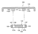
- FIG. 1 is a cross-sectional view illustrating an overall configuration of a key switch structure according to Embodiment 1.
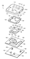
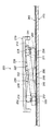
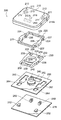
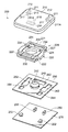
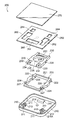
- FIG. It is the disassembled perspective view seen from diagonally upward which shows the whole structure of the key switch structure which concerns on Embodiment 1.
- FIG. It is the top view which looked at the place which assembled
- FIG. 6A a cross-sectional view of the key top taken along the plane AA in FIG. 6A as viewed from the rotary support claw, and the second link member in the plane B- in FIG. 6B. It is sectional drawing which looked at the cross section cut
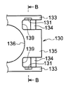
- FIG. 5 is an enlarged plan view showing an engagement relationship between a protrusion formed on a rotation support claw of a key top in the key switch structure according to the first embodiment and a concave portion of a second link member. It is an enlarged side view which shows the said engagement relationship. It is a top view which shows the structure which looked at the rotation support nail
- a cross-sectional view of the key top taken along the plane AA in FIG. 9A as viewed from the rotary support claw, and the second link member in the plane B- in FIG. 9B. It is sectional drawing which looked at the cross section cut
- a cross-sectional view of the key top taken along the plane AA in FIG. 13A as viewed from the rotary support claw, and the second link member in the plane B- in FIG. 13B. It is sectional drawing which looked at the cross section cut
- FIG. 17B is a cross-sectional view of the key top taken along a plane CC in FIG. 17A as viewed toward the rotation support claw.
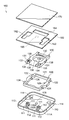
- FIG. 10 is a cross-sectional view illustrating an overall configuration of a key switch structure according to a seventh embodiment. It is the disassembled perspective view seen from diagonally upward which shows the whole structure of the key switch structure concerning Embodiment 7.
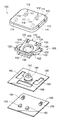
- the key switch structure concerning Embodiment 7 it is an exploded perspective view seen from the slanting upper part which shows the state where the 1st link member and the 2nd link member combined and constituted the link mechanism. It is the disassembled perspective view seen from diagonally downward which shows the whole structure of the key switch structure concerning Embodiment 7.
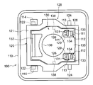
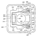
- FIG. It is the top view which looked at the place which assembled
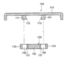
- the key switch structure 100 which is a first example of a key switch structure of the present invention will be described with reference to the drawings.
- the key switch structure 100 includes a key top 110, a link mechanism 128 including a first link member 120 and a second link member 130, and an example of an elastic member.
- the rubber dome 140, the membrane sheet 160, and the back plate 170 to which the first holder 150 and the second holder 152 are attached are configured.
- the first link member 120 is another link member of the present invention
- the second link member 130 is one link member of the present invention.
- the back plate 170 is a plate made of a material having a certain degree of hardness and rigidity, such as a metal or a hard resin.
- the membrane sheet 160 is configured such that an upper sheet 160A on which a wiring pattern is printed and a lower sheet 160C are bonded with a spacer sheet 160B interposed therebetween. Further, the membrane sheet 160 is formed of a flexible material that is attached to the surface of the back plate 170.
- holes 162, 164 are formed in the membrane sheet 160 in accordance with the positions of the first holder 150 and the second holder 152.
- the membrane sheet 160 is stuck on the back plate 170 with the first holder 150 and the second holder 152 protruding from the holes 162 and 164, respectively.
- a contact portion 166 is provided at the center of the membrane sheet 160.
- the contact portion 166 includes an upper contact 166A provided on the upper sheet 160A and a lower contact 166B provided on the lower sheet 160C.
- the rubber dome 140 is fixed between the membrane sheet 160 and the key top 110 with an adhesive or the like.
- the rubber dome 140 is formed in a substantially cup shape using rubber or the like as a material, and has a fitting hole 142 in the upper center. Further, a contact pressing portion 144 is formed to protrude toward the membrane sheet 160 at the center of the inner surface of the rubber dome 140.
- the key top 110 When the key top 110 is pressed, the key top 110 moves while maintaining parallel to the membrane sheet 160 (back plate 170) by the action of a link mechanism 128 described later.
- the rubber dome 140 is compressed and deformed, and the contact pressing portion 144 formed inside presses the portion of the membrane sheet 160 where the contact portion 166 is provided.
- the upper contact 166A and the lower contact 166B come into contact with each other and are electrically connected to be in a closed state as a switch.
- each component When the pressing of the key top 110 is released, each component returns to the original state by the restoring force (elasticity) of the rubber dome 140 and the membrane sheet 160. And since the contact part 166 of the membrane sheet 160 loses a contact and an electrical contact is cut
- first link member 120 the second link member 130, and the link mechanism 128 will be described.
- first link member 120 and the second link member 130 have a nested structure in which the second link member 130 is fitted inside the first link member 120.
- the first link member 120 and the second link member 130 constitute a pantograph type link mechanism 128.
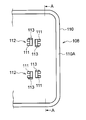
- the first link member 120 is a link member outside the link mechanism 128 and includes a frame body 121 formed in a substantially rectangular frame shape, a pair of rotating pins 124, and a pair of The sliding pin 122 and a pair of rotating shafts 126 are provided.
- the pair of rotation pins 124 is formed on one end side of the frame body 121 and is inserted into the first holder 150 of the back plate 170 and held rotatably.
- the pair of sliding pins 122 are formed on the other end side of the frame body 121, and in the horizontal direction on the back side (side facing the membrane sheet 160) of the key top 110, in other words, along the surface direction of the membrane sheet 160. Holds slidable.
- the pair of rotating shafts 126 protrudes inward from the center portion of the frame body 121.
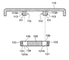
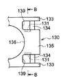
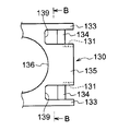
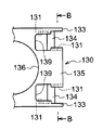
- the second link member 130 is a link member inside the link mechanism 128, and a circular escape hole 136 for escaping the rubber dome 140 is opened at the center. ing. Therefore, the second link member 130 also has a frame shape as a whole.
- the edge on the one end side of the second link member 130 is recessed in two directions toward the escape hole 136, in other words, in the direction toward the other end side, and is formed into a cut portion 139 parallel to each other.
- a portion between the two cut portions 139 is an inner ladder portion 135, and a portion outside each cut portion 139 is an outer ladder portion 133.
- a rotation pin 134 is formed between the outer ladder portion 133 and the inner ladder portion 135, in other words, between a pair of opposite side wall surfaces of the respective cut portions 139. ing.
- the second link member 130 is rotatably held on the back surface of the key top 110 by the rotation pin 134.
- An example of the engaging portion of the present invention is an inner surface of the outer ladder portion 133, in other words, a portion between the rotating pin 134 and the bottom surface of the notch portion 139 on the outer side wall surface of the notch portion 139.
- a certain recess 131 is formed. The recess 131 opens downward, in other words, toward the membrane sheet 160 (back sheet 170), but closes upward.
- the edge on the other end side of the second link member 130 is recessed in one direction toward the escape hole 136, in other words, toward the one end side.
- a sliding pin 132 is formed between a pair of opposing side wall surfaces of the recessed portion. The sliding pin 132 is inserted into the second holder 152 of the back plate 170 and is slidably held along the horizontal direction.
- a shaft hole 138 into which the rotation shaft 126 of the first link member 120 is fitted is formed at the center of the second link member 130.
- the first link member 120 and the second link member 130 are supported so as to be rotatable relative to each other when the rotating shaft 126 of the first link member 120 is fitted into the shaft hole 138 of the second link member 130.
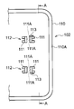
- a pair of rotation support portions 112 and a pair of slide support portions 114 are provided on the back surface of the key top 110.
- a pair of rotation support part 112 supports the rotation pin 134 of the 2nd link member 130 so that rotation is possible.
- the pair of slide support portions 114 support the slide pin 122 of the first link member 120 so that the slide pin 122 can be rotated and translated (slidable) in the horizontal direction (direction along the surface on the back side of the key top 110). .
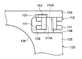
- each of the rotation support portions 112 includes a pair of rotation support claws 111.
- a rotation support surface 111A which is a cylindrical concave surface having a radius of curvature matched to the outer peripheral surface of the rotation pin 134, is formed.
- a groove is formed on the surface of the support surface of the rotation pin 134 opposite to the side on which the rotation support surface 111A is formed. Therefore, the rotation support claw 111 has a U-shaped cross section that is recessed toward the rotation support surface 111A when viewed from below, in other words, a C-shaped cross section.
- the rotation support claw 111 near the slide support portion 114, in other words, the lower end portion of the outer side wall of the rotation support claw 111 on the key center side, A projection 113 that engages with the recess 131 of the second link member 130 is provided.
- the protrusion 113 is an example of the engaged portion of the present invention.
- the protrusion 113 has a wedge-shaped cross section that expands upward.
- FIGS. 5 and 8A in a state where the second link member 130 is assembled to the key top 110, the space between the inner side surface of the rotation support claw 111 and the inner ladder portion 135 of the second link member 130 is shown. In other words, a gap is formed between the inner side surface of the rotation support claw 111 and the side wall surface of the second link member 130 on the side opposite to the side where the recess 131 is formed.
- the key switch structure 100 of Embodiment 1 can be assembled along the following procedures. First, the second link member 130 is fitted inside the first link member 120, and the rotation shaft 126 of the first link member 120 is fitted into the shaft hole 138 of the second link member 130 to constitute the link mechanism 128.
- the rotation pin 124 of the first link member 120 in the link mechanism 128 is fitted into the first holder 150 of the back plate 170.
- the sliding pin 132 of the second link member 130 is fitted into the second holder 152 of the back plate 170.
- the rotation pin 134 When the rotation pin 134 is fitted into the rotation support portion 112 of the key top 110, the rotation pin 134 is inserted between the pair of rotation support claws 111 constituting the rotation support portion 112 and supported by the rotation support surface 111A.
- the protrusion 113 protrudes from the lower end portion of the outer surface of one of the pair of rotation support claws 111. For this reason, when the rotation pin 134 is inserted between the rotation support claws 111, the projection 113 interferes with the inner surface of the outer ladder portion 133 in the second link member 130, in other words, the outer surface of the cut portion 139.
- the rotation support claw 111 When the projection 113 of the rotation support claw 111 gets over the outer ladder 133, the rotation support claw 111 returns to the position before elastic deformation. As a result, the rotation pin 134 is fitted into the rotation support surface 111 ⁇ / b> A, and at the same time, the protrusion 113 engages with the recess 131 formed in the outer ladder 133.
- the rubber dome 140 urges the key top 110 in a direction away from the membrane sheet 160 (back plate 170). This urging force acts in a direction in which the crossing angle between the first link member 120 and the second link member 130 becomes large.
- the rotation pin 124 of the first link member 120 rotates inside the first holder 150 of the back plate 170.
- the rotation pin 134 of the second link member 130 rotates inside the rotation support portion 112 of the key top 110.
- the slide pin 122 of the first link member 120 slides horizontally in the direction away from the rotation pin 134 of the second link member 130 inside the slide support portion 114 of the key top 110.
- the sliding pin 132 of the second link member 130 slides horizontally in the direction away from the rotation pin 124 of the first link member 120 inside the second holder 152 of the back plate 170.
- the first link member 120 and the second link member 130 rotate in a direction in which the crossing angle becomes smaller as a whole. Therefore, the key top 110 moves toward the membrane sheet 160 (back plate 170) while maintaining a horizontal state, and compresses and deforms the rubber dome 140. And the contact pressing part 144 presses the contact part 166 of the membrane sheet 160, and it will be in a closed state as a switch.
- the key top 110 When the hand is released from the key top 110, the key top 110 is kept parallel by the link mechanism 128, and the height before pressing down in the direction away from the membrane sheet 160 (back plate 170) by the action of the rubber dome 140 and the link mechanism 128. Return. Then, the contact pressing part 144 is separated from the contact part 166 of the membrane sheet 160 and is opened as a switch (see FIG. 1).
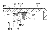
- the protrusion 113 of the rotation support claw 111 is fitted into the recess 131 provided in the outer ladder portion 133. .
- the upper surface 113 ⁇ / b> A of the protrusion 113 is in a state facing the ceiling surface 131 ⁇ / b> A of the recess 131. Therefore, when the key top 110 is lifted to some extent with respect to the link mechanism 128, the protrusion 113 is caught on the ceiling surface 131A of the recess 131, and the key top 110 cannot be lifted any more.
- the key top 110 is not easily detached from the link mechanism 128, specifically, the second link member 130. As a result, the key top 110 cannot be removed to the extent that a fingernail or the like is caught on the key top 110 when the key is pressed.
- the second link member 130 is connected to the outer surface of the rotation support claw 111 and the outer ladder portion 133 both when the key top 110 is raised and lowered. It rotates with respect to the rotation support claw 111 of the key top 110 while maintaining contact with the inner surface. As a result, the key top 110 is prevented from rotating with respect to the link mechanism 128.
- the rotation support claw 111 is thin because it has a U-shaped cross section, and even when the thickness of the ceiling of the key top 110 becomes thin, molding defects such as sink marks occur in the portion of the locking claw. Can be suppressed.
- the configurations of the back plate 170, the first holder 150, the second holder 152, the membrane sheet 160, the rubber dome 140, and the first link member 120 are the same as those of the key switch structure 100 of the first embodiment. Further, the configuration of the slide support portion 114 in the key top 110 is the same as that of the key switch structure 100 of the first embodiment.
- the recess 131 has a bottom surface of the notch 139 across the rotation pin 134 on the inner surface of the outer ladder 133. Is formed on the opposite side. In other words, the recess 131 is formed in a portion closer to the end than the rotation pin 134 on the outer side wall surface of the cut portion 139.
- the protrusion 113 to be fitted in the recess 131 is provided on the rotary claw 111 on the side close to the outer wall 110 ⁇ / b> A of the key top 110. In other words, the protrusion 113 is provided on the outer side wall of the rotation support claw 111 on the key peripheral side. And the protrusion 113 is made into the wedge shape which spreads upwards similarly to the key switch structure 100 of Embodiment 1.
- the second link member 130 has the same configuration as the second link member 130 in the key switch structure 100 of the first embodiment except for the above points.
- the assembly procedure of the key switch structure 102 is the same as that of the key switch structure 100 of the first embodiment.
- the rotation pin 134 of the second link member 130 is inserted between the rotation support claws 111 of the key top 110, the rotation support claw 111 on the key peripheral side is formed between the protrusion 113 and the outer ladder portion 133.
- the key switch structure 100 is the same as that of the key switch structure 100 of the first embodiment except that it is elastically deformed toward the inner ladder 135 of the second link member 130 due to mutual interference.
- a protrusion 113 is provided on the rotation support claw 111 on the key peripheral side in the rotation support portion 112.
- the recess 131 is provided on the inner surface of the outer ladder 133 of the second link member 130. Therefore, the key switch structure 102 has a vertical shift when the key top 110 is lifted by the claw as compared with the key switch structure 100 of the first embodiment in which the protrusion 113 is provided on the rotation support claw 111 on the key center side. However, it has the feature of being less.
- the configurations of the back plate 170, the first holder 150, the second holder 152, the membrane sheet 160, the rubber dome 140, and the first link member 120 are the same as those of the key switch structure 100 of the first embodiment. Further, the configuration of the slide support portion 114 in the key top 110 is the same as that of the key switch structure 100 of the first embodiment.
- the recess 131 is a portion between the rotation pin 134 on the side surface of the inner ladder portion 135 and the bottom surface of the cut surface 139. Is formed. In other words, the recess 131 is formed in a portion between the rotation pin 134 and the bottom surface of the cut surface 139 on the inner side wall surface of the cut portion 139.
- the protrusion 113 to be engaged with the recess 131 is provided on the inner surface of the rotation support claw 111 on the key center side of the key top 110.
- the protrusion 113 has a wedge shape that spreads upward as in the key switch structure 100 of the first embodiment.
- the second link member 130 has the same configuration as the second link member 130 in the key switch structure 100 of the first embodiment except for the above points.
- the assembly procedure of the key switch structure 104 is the same as that of the key switch structure 100 of the first embodiment.
- the rotation pin 134 of the second link member 130 is inserted between the rotation support claws 111 of the key top 110, the rotation support claw 111 on the key center side is formed between the protrusion 113 and the inner ladder 135.
- the key switch structure 100 is the same as that of the first embodiment except that the second link member 130 is elastically deformed in the direction toward the outer ladder 133 due to the mutual interference.
- a protrusion 113 is provided on the inner surface of the rotation support claw 111 on the key center side in the rotation support portion 112.
- the recess 131 is provided on the side surface of the inner ladder portion 135 of the second link member 130.
- the inner ladder 135 is less likely to be deformed than the outer ladder 133. Therefore, in the key switch structure 104 of the third embodiment, the key top 110 is linked to the key switch structure 100 of the first embodiment in which the protrusion 113 is provided on the outer side surface of the rotation support claw 111 on the key center side. It is difficult to disengage from the mechanism 128.
- Embodiment 4 a key switch structure 106 as a fourth example of the key switch structure of the present invention will be described with reference to the drawings.
- the recess 131 has a bottom surface of the notch 139 with respect to the rotation pin 134 on the side surface of the inner ladder 135 of the second link member 130. It is formed in the part on the opposite side.
- the protrusion 113 to be engaged with the recess 131 is provided on the inner surface of the rotation support claw 111 on the key peripheral side of the key top 110.
- the key switch structure 106 has the same configuration as the key switch structure 104 of the third embodiment.
- the protrusion 113 is provided on the rotation support claw 111 on the key peripheral side in the rotation support portion 112.
- the recessed part 131 is provided in the side surface of the inner ladder part 135 of the 2nd link member 130, ie, the side wall surface inside the notch part 139. Therefore, the key switch structure 106 has an up-down direction when the key top 110 is lifted by the claw, compared to the key switch structure 104 of the third embodiment in which the protrusion 113 is provided on the rotation support claw 111 on the key center side. However, it has the feature of being less.
- the key switch structure 108 is provided not only on the outer side surface of the rotation support claw 111 on the key center side but also on the inner side surface of the rotation support claw 111 on the key peripheral side.
- the projection 113 is provided in a projecting manner.
- a recess 131 is also formed in a portion of the insertion portion 139 opposite to the bottom surface.
- the portion where the recess 131 is provided faces inward with respect to the portion where the recess 131 is not provided with the rotation pin 134 as a boundary. In other words, it protrudes toward the inner ladder part 135. And the level
- the portion provided with the recess 131 on the inner side wall surface of the notch 139 faces outward with respect to the portion where the recess is not provided with the rotation pin 134 as a boundary, in other words, on the outer ladder portion 133. Protrusively. Similar to the outer side wall surface, a step is formed between a portion of the inner side wall portion where the concave portion 131 is provided and a portion where the concave portion 131 is not provided.
- the second link member has a crank shape that spreads toward the outer ladder portion 133.
- the surface opposite to the side on which the projection 113 of the rotation support claw 111 on the key center side and the rotation support claw 111 on the key peripheral side is provided.
- a gap is formed between the side wall surface of the cut portion 139 where the recess 131 is not provided.
- the key switch structure 108 has the same configuration as the key switch structure 100 of the first embodiment.
- the protrusion 113 is provided on each of the rotation support claws 111 on the key peripheral side and the key center side in the rotation support portion 112.
- a recess 131 is provided on both the inner surface of the outer ladder portion 133 and the side surface of the inner ladder portion 135 of the second link member 130. Therefore, the key switch structure 108 has a key top 110 that is different from the key switch structure in which the protrusion 113 is provided on one of the rotation support claw 111 on the key center side and the rotation support claw 111 on the key peripheral side. It has a feature that it is further difficult to come off from the link mechanism 128.
- the configurations of the back plate 170, the first holder 150, the second holder 152, the membrane sheet 160, the rubber dome 140, and the first link member 120 are the same as those of the key switch structure 100 of the first embodiment. Further, the configuration of the slide support portion 114 in the key top 110 is the same as that of the key switch structure 100 of the first embodiment.
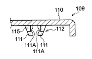
- a concave portion 115 as an example of an engaged portion is formed on the outer side surface of the rotation support claw 111 on the key center side. Yes. Therefore, the thickness d1 of the rotation support claw 111 on the key center side is larger by the depth of the recess 115 than the thickness d2 of the rotation support claw 111 on the key peripheral side.
- the recess 115 is open toward the slide support 114, in other words, toward the key center, but closed toward the back plate 170, that is, downward.
- a protrusion 137 is formed as an example of an engaging portion that engages with the recess 115 of the rotation support claw 111. As shown in FIG. 18, the protrusion 137 has a wedge shape that extends downward.
- the second link member 130 has the same configuration as the second link member 130 in the key switch structure 100 of Embodiment 1 except for the above points (see FIG. 17C).
- the assembly procedure of the key switch structure 109 is the same as that of the key switch structure 100 of the first embodiment.
- the rotation pin 134 of the second link member 130 is inserted between the rotation support claws 111 of the key top 110, due to the mutual interference between the protrusion 137 of the outer ladder 133 and the rotation support claw 111 on the key center side,
- the rotation support claws 111 on the key center side are deformed toward each other, in other words, toward the inner ladder 135, and the outer ladder 133 is elastically deformed outward.
- the recess 115 is closed downward, and the protrusion 137 has a wedge shape that extends downward.
- the protrusion 137 engages with the recess 115 of the rotation support claw 111.
- the bottom surface 137 ⁇ / b> A of the protrusion 137 shown in FIG. 18 is in a state facing the bottom surface 115 ⁇ / b> A of the recess 115. Therefore, when the key top 110 is lifted to some extent relative to the link mechanism 128, the protrusion 137 is caught on the bottom surface 115A of the recess 115 and cannot be lifted any further.
- the thickness d1 of the rotation support claw 111 on the key center side where the recess 115 is provided is larger than the thickness d2 of the rotation support claw 111 on the key center side in the key switch structure 100 of the first embodiment.
- the key switch structure of the sixth embodiment has a key top 110 having a link mechanism compared to a key switch structure in which the thickness of the rotation support claw on the key center side and the rotation support claw 111 on the key peripheral side is d2. It is hard to come off from 128.
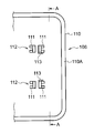
- the key switch structure 200 includes a key top 210, a link mechanism 228 configured to include a first link member 220 and a second link member 230, and a rubber dome as an elastic member. 240, the membrane sheet 260, and the back plate 270 to which the first holder 250 and the second holder 252 are attached.
- the first link member 220 and the second link member 230 correspond to one link member and another link member of the present invention.
- the back plate 270 is a plate made of a material having a certain degree of hardness and rigidity, such as a metal or a hard resin.
- the membrane sheet 260 has a structure in which two sheets on which a wiring pattern is printed with a spacer sheet (not shown) sandwiched therebetween, that is, an upper sheet and a lower sheet (not shown) are bonded to each other. It is made of a flexible material that is affixed to.
- the membrane sheet 260 is stuck on the back plate 270 such that the first holder 250 and the second holder 252 protrude from the holes 262 and 264, respectively.
- the holes 262 and 264 are formed in the membrane sheet 260 in accordance with the positions of the first holder 250 and the second holder 252.
- a contact portion 266 is provided at the center of the membrane sheet 260.
- a rubber dome 240 is fixed to the key top 210 on the contact portion 266 with an adhesive or the like.
- the rubber dome 240 is formed in a substantially cup shape using rubber or the like as a material, and has a fitting hole 242 in the upper center.
- a contact pressing portion 244 is formed to protrude toward the membrane sheet 260 at the center of the inner surface of the rubber dome 240.
- first link member 220, the second link member 230, and the link mechanism 228 will be described.
- first link member 220 and the second link member 230 have a nested structure in which the second link member 230 is fitted inside the first link member 220.
- the first link member 220 and the second link member 230 constitute a pantograph type link mechanism 228.
- the first link member 220 is a link member outside the link mechanism 228.
- the first link member 220 is formed on a frame body 221 formed in a substantially rectangular frame shape, a pair of rotating pins 224 formed on one end side of the frame body 221, and the other end side of the frame body 221.
- a pair of sliding pins 222 and a pair of rotating shafts 226 projecting inward from the center of the frame 221 are provided.
- the pair of rotating pins 224 are rotatably held on the back surface of the key top 210 (the membrane sheet 260, in other words, the surface facing the back sheet 270).
- the pair of sliding pins 222 is held slidably along the horizontal direction, in other words, along the surface direction of the membrane plate 260, at the sliding support portion 252 of the back plate 270.
- the second link member 230 is a link member inside the link mechanism 228.
- a circular escape hole 236 for escaping the rubber dome 240 is opened at the center of the second link member 230. Therefore, the second link member 230 has a frame shape as a whole.
- the edge on the one end side of the second link member 230 is recessed in two directions toward the escape hole 236, in other words, in the direction toward the other end side, and is formed as a cut portion 239 parallel to each other.
- a portion between the two cut portions 239 is an inner ladder portion 235, and a portion outside each cut portion 239 is an outer ladder portion 233. Therefore, the outer ladder portion 233 is formed at two locations, and the inner ladder portion 235 is formed at one location.
- a rotation pin 234 is formed between the outer ladder 233 and the inner ladder 235, respectively.
- the second link member 230 is rotatably held by the first holder 250 of the back plate 270 at the rotation pin 234.
- the edge on the other end side of the second link member 230 is recessed in one direction toward the escape hole 236, in other words, toward the one end side.
- a sliding pin 232 is formed between a pair of opposing side wall surfaces of the recessed portion. As will be described later, the sliding pin 232 is slidably held along the horizontal direction on the back surface of the key top 210.
- a shaft hole 238 into which the rotation shaft 226 of the first link member 220 is fitted is formed in the center portion of the second link member 230.
- the first link member 220 and the second link member 230 are rotatably supported by the rotation shaft 226 of the first link member 220 fitting into the shaft hole 238 of the second link member 230.
- a pair of rotation support portions 212 and a pair of slide support portions 214 are provided on the back surface of the key top 210.
- a pair of rotation support part 212 supports the rotation pin 224 of the 1st link member 230 so that rotation is possible.
- the pair of slide support portions 214 support the slide pin 232 of the second link member 230 so that the slide pin 232 can be rotated and translated (slidable) in the horizontal direction (the direction along the surface on the back side of the key top 210). .
- each of the rotation support portions 212 includes a pair of rotation support claws 211.
- a rotation support surface 211 ⁇ / b> A that is a cylindrical concave surface having a radius of curvature matched to the outer peripheral surface of the rotation pin 224 is formed.
- the rotation pin 224 is supported on the rotation support surface 211A.
- a groove is formed on the surface of the rotation support claw 211 opposite to the side on which the rotation support surface 211A is formed. For this reason, the rotation support claw 211 has a U-shaped cross section that is recessed toward the rotation support surface 211A as viewed from below, in other words, a C-shaped cross section.
- a protrusion 213 that engages with the recess 227 of the first link member 220 is provided at the lower end portion of the inner side wall of the rotation support claw 211 on the key peripheral side.
- the protrusion 213 has a wedge-shaped cross section that expands upward.
- the key switch structure 200 of the seventh embodiment can be assembled according to the same procedure as the key switch structure 100 of the first embodiment.
- the second link member 230 is fitted inside the first link member 220, and the rotation shaft 226 of the first link member 220 is fitted into the shaft hole 238 of the second link member 230 to constitute the link mechanism 228.
- the rotation pin 234 of the second link member 230 in the link mechanism 228 is fitted into the first holder 250 of the back plate 270.
- the sliding pin 222 of the first link member 220 is fitted into the second holder 252 of the back plate 270.
- the rotation pin 224 When the rotation pin 224 is fitted into the rotation support portion 212 of the key top 210, the rotation pin 224 is inserted between the pair of rotation support claws 211 constituting the rotation support portion 212 and is fitted between the rotation support surfaces 211A. .
- the rotation pin 224 since the protrusion 213 protrudes from the lower end portion of the inner surface of the rotation support claw 211 on the key peripheral side among the pair of rotation support claws 211, the rotation pin 224 is supported to rotate. When inserted between the claws 211, the protrusion 213 interferes with the outer surface of the frame 211 in the first link member 220.
- the rotation support claw 211 on the key center side and the rotation support claw 211 on the key peripheral side are elastically deformed in a direction in which the interval increases, and the rotation support claw 211 on the key peripheral side is separated from each other in other words.
- the elastic deformation is performed in a direction away from the one link member 220. Thereby, the protrusion 213 gets over the outer surface of the frame body 221.
- the rotation support claw 211 When the protrusion 213 of the rotation support claw 211 gets over the outer surface of the frame body 221, the rotation support claw 211 returns to the position before elastic deformation. Thereby, the rotation pin 224 is supported by the rotation support surface 211 ⁇ / b> A, and the protrusion 213 is engaged with the recess 227.
- the first link member 220 and the second link member 230 intersect with each other in an X shape to constitute a link mechanism 228.
- the link mechanism 228 is held by the back plate 170 at the sliding pin 222 of the first link member 220 and the rotating pin 234 of the second link member 230, and at the same time as the rotating pin 224 of the first link member 220 and the second pin 224.
- the key top 210 is held by the sliding pin 232 of the two link member 230.
- the rubber dome 240 biases the key top 210 in a direction away from the membrane sheet 260. This urging force acts in a direction in which the crossing angle between the first link member 220 and the second link member 230 becomes large.
- the sliding pin 222 of the first link member 220 slides in the direction away from the rotating pin 234 of the second link member 230 inside the sliding support portion 252 of the back plate 270. Further, the sliding pin 232 of the second link member 230 slides in the direction away from the rotating pin 224 of the first link member 220 inside the sliding support portion 214 of the key top 210. At the same time, the rotation pin 224 of the first link member 220 rotates inside the rotation support portion 212 of the key top 210. Further, the rotation pin 234 of the second link member 230 rotates inside the first holder 250 of the back plate 270.
- the first link member 220 and the second link member 230 rotate in a direction in which the crossing angle becomes smaller as a whole. Therefore, the key top 210 moves toward the membrane sheet 260 (back plate 270) while maintaining a horizontal state, and compresses and deforms the rubber dome 240. Then, the contact pressing part 244 presses the contact part 266 of the membrane sheet 260 to be closed as a switch.
- the key top 210 When the hand is released from the key top 210, the key top 210 is kept parallel by the link mechanism 228, and the height before being pressed in the direction away from the membrane sheet 260 (back plate 270) by the action of the rubber dome 240 and the link mechanism 228. It will return. Then, the contact pressing part 244 is separated from the contact part 266 of the membrane sheet 260 and is opened as a switch (see FIG. 19).
- the protrusion 213 of the rotation support claw 211 engages with the recess 227 of the first link member 220. Then, the upper surface of the protrusion 213 is in a state facing the ceiling surface of the recess 227. For this reason, if the key top 210 is lifted to a certain degree with respect to the link mechanism 228, the protrusion 213 is caught on the ceiling surface of the recess 237 and cannot be lifted any further. Therefore, even when the keyboard is thinned, the key top 210 is difficult to be detached from the link mechanism 228. As a result, the key top 210 cannot be removed to the extent that a fingernail or the like is caught on the key top 210 when the key is pressed.
- the rotation support claw 211 has a U-shaped cross section and is thin. For this reason, even when the thickness of the ceiling of the key top 210 is thin, it is possible to prevent molding defects such as sink marks from occurring in the portion of the locking claw.
Landscapes
- Push-Button Switches (AREA)
Priority Applications (2)
| Application Number | Priority Date | Filing Date | Title |
|---|---|---|---|
| CN201280030208.7A CN103650087A (zh) | 2011-12-27 | 2012-10-25 | 键开关结构 |
| US14/131,602 US20140138225A1 (en) | 2011-12-27 | 2012-10-25 | Key switch structure |
Applications Claiming Priority (2)
| Application Number | Priority Date | Filing Date | Title |
|---|---|---|---|
| JP2011-286648 | 2011-12-27 | ||
| JP2011286648A JP2013134969A (ja) | 2011-12-27 | 2011-12-27 | キースイッチ構造 |
Publications (1)
| Publication Number | Publication Date |
|---|---|
| WO2013099416A1 true WO2013099416A1 (ja) | 2013-07-04 |
Family
ID=48696918
Family Applications (1)
| Application Number | Title | Priority Date | Filing Date |
|---|---|---|---|
| PCT/JP2012/077638 Ceased WO2013099416A1 (ja) | 2011-12-27 | 2012-10-25 | キースイッチ構造 |
Country Status (4)
| Country | Link |
|---|---|
| US (1) | US20140138225A1 (enExample) |
| JP (1) | JP2013134969A (enExample) |
| CN (1) | CN103650087A (enExample) |
| WO (1) | WO2013099416A1 (enExample) |
Cited By (1)
| Publication number | Priority date | Publication date | Assignee | Title |
|---|---|---|---|---|
| CN103413709A (zh) * | 2013-08-14 | 2013-11-27 | 北京东方惠尔图像技术有限公司 | 按键组件和超声诊断系统的控制面板组件 |
Families Citing this family (4)
| Publication number | Priority date | Publication date | Assignee | Title |
|---|---|---|---|---|
| CN204927141U (zh) * | 2015-09-06 | 2015-12-30 | 东莞市凯华电子有限公司 | 一种薄形键盘开关 |
| WO2020122887A1 (en) * | 2018-12-12 | 2020-06-18 | Hewlett-Packard Development Company, L.P. | Rolling elements-based pivoting supports for keyboards |
| JP7484436B2 (ja) * | 2020-01-15 | 2024-05-16 | オムロン株式会社 | スイッチ、スイッチアッセンブリ及び操作装置 |
| JP7516874B2 (ja) * | 2020-06-02 | 2024-07-17 | オムロン株式会社 | スイッチ、スイッチアッセンブリ及びキー入力装置 |
Citations (2)
| Publication number | Priority date | Publication date | Assignee | Title |
|---|---|---|---|---|
| JPH05290673A (ja) * | 1991-11-19 | 1993-11-05 | Brother Ind Ltd | キースイッチ装置 |
| JP2008293923A (ja) * | 2007-05-28 | 2008-12-04 | Oki Electric Ind Co Ltd | キースイッチ構造 |
Family Cites Families (7)
| Publication number | Priority date | Publication date | Assignee | Title |
|---|---|---|---|---|
| JP2800617B2 (ja) * | 1993-01-06 | 1998-09-21 | ブラザー工業株式会社 | キースイッチ |
| US5758763A (en) * | 1995-08-17 | 1998-06-02 | Hosiden Corporation | Pantograph type keyboard switch |
| JP3922854B2 (ja) * | 1999-12-07 | 2007-05-30 | 富士通コンポーネント株式会社 | キースイッチ及びキーボード |
| CN1220228C (zh) * | 2001-04-25 | 2005-09-21 | 达方电子股份有限公司 | 键盘的可掀离顶盖按键装置 |
| CN201282054Y (zh) * | 2008-09-03 | 2009-07-29 | 邱灯锋 | 键盘结构 |
| TWI408715B (zh) * | 2009-09-25 | 2013-09-11 | Primax Electronics Ltd | 按鍵結構以及具有此結構之鍵盤 |
| JP5682449B2 (ja) * | 2011-05-20 | 2015-03-11 | 沖電気工業株式会社 | キースイッチ構造 |
-
2011
- 2011-12-27 JP JP2011286648A patent/JP2013134969A/ja not_active Ceased
-
2012
- 2012-10-25 CN CN201280030208.7A patent/CN103650087A/zh active Pending
- 2012-10-25 WO PCT/JP2012/077638 patent/WO2013099416A1/ja not_active Ceased
- 2012-10-25 US US14/131,602 patent/US20140138225A1/en not_active Abandoned
Patent Citations (2)
| Publication number | Priority date | Publication date | Assignee | Title |
|---|---|---|---|---|
| JPH05290673A (ja) * | 1991-11-19 | 1993-11-05 | Brother Ind Ltd | キースイッチ装置 |
| JP2008293923A (ja) * | 2007-05-28 | 2008-12-04 | Oki Electric Ind Co Ltd | キースイッチ構造 |
Cited By (1)
| Publication number | Priority date | Publication date | Assignee | Title |
|---|---|---|---|---|
| CN103413709A (zh) * | 2013-08-14 | 2013-11-27 | 北京东方惠尔图像技术有限公司 | 按键组件和超声诊断系统的控制面板组件 |
Also Published As
| Publication number | Publication date |
|---|---|
| CN103650087A (zh) | 2014-03-19 |
| US20140138225A1 (en) | 2014-05-22 |
| JP2013134969A (ja) | 2013-07-08 |
Similar Documents
| Publication | Publication Date | Title |
|---|---|---|
| JP5682449B2 (ja) | キースイッチ構造 | |
| JP4371987B2 (ja) | プッシュオンスイッチ | |
| WO2013099416A1 (ja) | キースイッチ構造 | |
| JP5256066B2 (ja) | プッシュスイッチ | |
| JP6634295B2 (ja) | スイッチ装置 | |
| JP2011060601A (ja) | キースイッチ装置及びキーボード | |
| JP2009009385A (ja) | キーボードおよび電子機器 | |
| JP2001297653A (ja) | キーボード装置およびキーボード装置を有する電子機器 | |
| JP5578959B2 (ja) | プッシュスイッチ | |
| JP5003286B2 (ja) | キースイッチ構造 | |
| TW201502866A (zh) | 薄型按鍵結構及其按壓模組 | |
| CN106814802B (zh) | 可携式电子装置 | |
| JP2013143355A (ja) | 電子装置 | |
| JP2006244977A (ja) | 押釦スイッチ | |
| JP4487892B2 (ja) | スイッチ装置の防水構造 | |
| JP5190008B2 (ja) | 情報処理装置 | |
| JP2007287347A (ja) | スイッチ装置 | |
| JP3180966U (ja) | プッシュスイッチ | |
| JP2009070671A (ja) | 押釦スイッチ | |
| JP2011100678A (ja) | 押釦スイッチ | |
| JP2007012428A (ja) | 操作スイッチ | |
| JP2011109545A (ja) | キーパッド | |
| CN119511616A (zh) | 下潜式滑动门盖组件与具有下潜式滑动门盖组件的投影设备 | |
| WO2023053554A1 (ja) | プッシュスイッチ | |
| JP2014179722A (ja) | 携帯端末装置 |
Legal Events
| Date | Code | Title | Description |
|---|---|---|---|
| 121 | Ep: the epo has been informed by wipo that ep was designated in this application |
Ref document number: 12861862 Country of ref document: EP Kind code of ref document: A1 |
|
| WWE | Wipo information: entry into national phase |
Ref document number: 14131602 Country of ref document: US |
|
| NENP | Non-entry into the national phase |
Ref country code: DE |
|
| 122 | Ep: pct application non-entry in european phase |
Ref document number: 12861862 Country of ref document: EP Kind code of ref document: A1 |