WO2013099416A1 - Key switch structure - Google Patents
Key switch structure Download PDFInfo
- Publication number
- WO2013099416A1 WO2013099416A1 PCT/JP2012/077638 JP2012077638W WO2013099416A1 WO 2013099416 A1 WO2013099416 A1 WO 2013099416A1 JP 2012077638 W JP2012077638 W JP 2012077638W WO 2013099416 A1 WO2013099416 A1 WO 2013099416A1
- Authority
- WO
- WIPO (PCT)
- Prior art keywords
- link member
- rotation support
- key
- switch structure
- key switch
- Prior art date
Links
Images


Classifications
-
- H—ELECTRICITY
- H01—ELECTRIC ELEMENTS
- H01H—ELECTRIC SWITCHES; RELAYS; SELECTORS; EMERGENCY PROTECTIVE DEVICES
- H01H13/00—Switches having rectilinearly-movable operating part or parts adapted for pushing or pulling in one direction only, e.g. push-button switch
- H01H13/02—Details
- H01H13/12—Movable parts; Contacts mounted thereon
- H01H13/14—Operating parts, e.g. push-button
-
- H—ELECTRICITY
- H01—ELECTRIC ELEMENTS
- H01H—ELECTRIC SWITCHES; RELAYS; SELECTORS; EMERGENCY PROTECTIVE DEVICES
- H01H3/00—Mechanisms for operating contacts
- H01H3/02—Operating parts, i.e. for operating driving mechanism by a mechanical force external to the switch
- H01H3/12—Push-buttons
- H01H3/122—Push-buttons with enlarged actuating area, e.g. of the elongated bar-type; Stabilising means therefor
- H01H3/125—Push-buttons with enlarged actuating area, e.g. of the elongated bar-type; Stabilising means therefor using a scissor mechanism as stabiliser
-
- H—ELECTRICITY
- H01—ELECTRIC ELEMENTS
- H01H—ELECTRIC SWITCHES; RELAYS; SELECTORS; EMERGENCY PROTECTIVE DEVICES
- H01H13/00—Switches having rectilinearly-movable operating part or parts adapted for pushing or pulling in one direction only, e.g. push-button switch
- H01H13/70—Switches having rectilinearly-movable operating part or parts adapted for pushing or pulling in one direction only, e.g. push-button switch having a plurality of operating members associated with different sets of contacts, e.g. keyboard
- H01H13/702—Switches having rectilinearly-movable operating part or parts adapted for pushing or pulling in one direction only, e.g. push-button switch having a plurality of operating members associated with different sets of contacts, e.g. keyboard with contacts carried by or formed from layers in a multilayer structure, e.g. membrane switches
- H01H13/705—Switches having rectilinearly-movable operating part or parts adapted for pushing or pulling in one direction only, e.g. push-button switch having a plurality of operating members associated with different sets of contacts, e.g. keyboard with contacts carried by or formed from layers in a multilayer structure, e.g. membrane switches characterised by construction, mounting or arrangement of operating parts, e.g. push-buttons or keys
Definitions
- the present invention relates to a key switch structure, and more particularly to a key switch structure used for a keyboard of an information processing device, a measuring device, a medical device, a personal computer, a word processor, or the like.
- a link mechanism is configured by combining an outer link member formed in a frame shape and an inner link member formed in a frame shape in an X shape.
- the link mechanism is provided between the key top and the back plate.
- the present invention has been made to solve the above-described problem, and an object of the present invention is to provide a key switch structure in which the key top is difficult to come off from the link mechanism.
- one end side is rotatably engaged with the rotation support portion provided on the back surface of the key top that is pressed down to conduct the contact, and the other end side is slidably held on the surface of the back plate.
- One link member and the one link member are rotatably connected, one end side is rotatably held on the surface of the back plate, and the other end side is slidable on the back surface of the key top.
- Another link member to be held a link mechanism that supports the key top so as to be capable of coming into contact with and separated from the back plate, an engagement portion provided in the one link member, and the rotation support portion
- a key switch structure having an engaged portion that engages with the engaging portion and restricts the key top from being detached from the one link member.
- the engagement portion is provided in one link member that is rotatably engaged with the rotation support portion on the back surface of the key top, and the engaged portion is provided in the rotation support portion. And since the engaging part of one link member is engaging with the to-be-engaged part of a rotation support part, even if it lifts a key top with respect to a link mechanism, a key top does not come off from the said link mechanism easily.
- the engaging portion is a recess formed in the one link member, and the back plate side is open, and the engaged portion is formed in the rotation support portion, and the opening extends from the opening to the recess. It is a protrusion that fits.
- the engaging portion is a recess formed in one link member and opened on the back plate side.
- the engaged portion is a protrusion that is provided in the rotation support portion and fits into the recess.
- the engaging portion is a protrusion formed on the one link member, the engaged portion is formed on the rotation support portion, the back plate side is closed, and the protrusion is It is a recessed part to fit.
- the engaging portion is a protrusion formed on one link member.
- the engaged portion is a recess provided in the rotation support portion, the back plate side being closed, and the projection being fitted therein. Therefore, even if the key top is lifted with respect to the link mechanism, the protrusion is applied to the wall on the back plate side of the recess, so that the key top is difficult to come off from one link member.
- a rotation pin is formed on one end side of the one link member, and the rotation support portion has a rotation support surface that is a concave surface that supports the rotation pin on a surface on a side facing each other. It has a pair of formed rotation support claws, the recess is formed in the vicinity of the rotation pin in the one link member, and the projection is formed in the rotation support claw.
- the rotation support claws are elastically deformed in the direction in which the rotation pins spread to each other, and the rotation pin is supported on the recessed surface.
- claw fits in the recessed part formed in the one link member. Therefore, the one link member can be mounted on the rotation support portion only by press-fitting the rotation pin between the rotation support claws until the rotation pin is supported by the recessed surface.
- a rotation pin is formed on one end side of the one link member, and the rotation support portion has a rotation support surface that is a concave surface that supports the rotation pin on a surface on a side facing each other.
- a pair of rotation support claws are formed, the protrusion is formed in the vicinity of the rotation pin in the one link member, and the recess is formed in the rotation support claw.
- the rotation support claws are elastically deformed in the direction in which the rotation pins spread to each other, and the rotation pin is supported on the recessed surface. And the protrusion of one link member is inserted in the recess of the rotation support claw. Therefore, the one link member can be attached to the rotation support portion on the back surface of the key top by simply press-fitting the rotation pin between the rotation support claws until the rotation pin is supported on the concave surface.
- a groove is formed on the surface of the rotation support claw opposite to the side on which the recessed surface is formed.
- the rotation support claw is thin by forming a groove on the surface of the rotation support claw opposite to the side where the concave surface is formed. For this reason, even when the thickness of the upper surface of the key top is reduced, it is possible to prevent molding defects such as sink marks from occurring in the portion where the rotation support claw is formed.
- a key switch structure in which the key top is not easily detached from the link mechanism.
- FIG. 1 is a cross-sectional view illustrating an overall configuration of a key switch structure according to Embodiment 1.
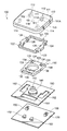
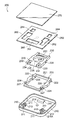
- FIG. It is the disassembled perspective view seen from diagonally upward which shows the whole structure of the key switch structure which concerns on Embodiment 1.
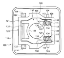
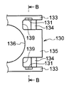
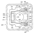
- FIG. It is the top view which looked at the place which assembled
- FIG. 6A a cross-sectional view of the key top taken along the plane AA in FIG. 6A as viewed from the rotary support claw, and the second link member in the plane B- in FIG. 6B. It is sectional drawing which looked at the cross section cut
- FIG. 5 is an enlarged plan view showing an engagement relationship between a protrusion formed on a rotation support claw of a key top in the key switch structure according to the first embodiment and a concave portion of a second link member. It is an enlarged side view which shows the said engagement relationship. It is a top view which shows the structure which looked at the rotation support nail
- a cross-sectional view of the key top taken along the plane AA in FIG. 9A as viewed from the rotary support claw, and the second link member in the plane B- in FIG. 9B. It is sectional drawing which looked at the cross section cut
- a cross-sectional view of the key top taken along the plane AA in FIG. 13A as viewed from the rotary support claw, and the second link member in the plane B- in FIG. 13B. It is sectional drawing which looked at the cross section cut
- FIG. 17B is a cross-sectional view of the key top taken along a plane CC in FIG. 17A as viewed toward the rotation support claw.
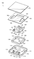
- FIG. 10 is a cross-sectional view illustrating an overall configuration of a key switch structure according to a seventh embodiment. It is the disassembled perspective view seen from diagonally upward which shows the whole structure of the key switch structure concerning Embodiment 7.
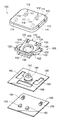
- the key switch structure concerning Embodiment 7 it is an exploded perspective view seen from the slanting upper part which shows the state where the 1st link member and the 2nd link member combined and constituted the link mechanism. It is the disassembled perspective view seen from diagonally downward which shows the whole structure of the key switch structure concerning Embodiment 7.
- FIG. It is the top view which looked at the place which assembled
- the key switch structure 100 which is a first example of a key switch structure of the present invention will be described with reference to the drawings.
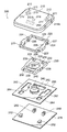
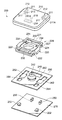
- the key switch structure 100 includes a key top 110, a link mechanism 128 including a first link member 120 and a second link member 130, and an example of an elastic member.
- the rubber dome 140, the membrane sheet 160, and the back plate 170 to which the first holder 150 and the second holder 152 are attached are configured.
- the first link member 120 is another link member of the present invention
- the second link member 130 is one link member of the present invention.
- the back plate 170 is a plate made of a material having a certain degree of hardness and rigidity, such as a metal or a hard resin.
- the membrane sheet 160 is configured such that an upper sheet 160A on which a wiring pattern is printed and a lower sheet 160C are bonded with a spacer sheet 160B interposed therebetween. Further, the membrane sheet 160 is formed of a flexible material that is attached to the surface of the back plate 170.
- holes 162, 164 are formed in the membrane sheet 160 in accordance with the positions of the first holder 150 and the second holder 152.
- the membrane sheet 160 is stuck on the back plate 170 with the first holder 150 and the second holder 152 protruding from the holes 162 and 164, respectively.
- a contact portion 166 is provided at the center of the membrane sheet 160.
- the contact portion 166 includes an upper contact 166A provided on the upper sheet 160A and a lower contact 166B provided on the lower sheet 160C.
- the rubber dome 140 is fixed between the membrane sheet 160 and the key top 110 with an adhesive or the like.
- the rubber dome 140 is formed in a substantially cup shape using rubber or the like as a material, and has a fitting hole 142 in the upper center. Further, a contact pressing portion 144 is formed to protrude toward the membrane sheet 160 at the center of the inner surface of the rubber dome 140.
- the key top 110 When the key top 110 is pressed, the key top 110 moves while maintaining parallel to the membrane sheet 160 (back plate 170) by the action of a link mechanism 128 described later.
- the rubber dome 140 is compressed and deformed, and the contact pressing portion 144 formed inside presses the portion of the membrane sheet 160 where the contact portion 166 is provided.
- the upper contact 166A and the lower contact 166B come into contact with each other and are electrically connected to be in a closed state as a switch.
- each component When the pressing of the key top 110 is released, each component returns to the original state by the restoring force (elasticity) of the rubber dome 140 and the membrane sheet 160. And since the contact part 166 of the membrane sheet 160 loses a contact and an electrical contact is cut
- first link member 120 the second link member 130, and the link mechanism 128 will be described.
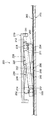
- first link member 120 and the second link member 130 have a nested structure in which the second link member 130 is fitted inside the first link member 120.
- the first link member 120 and the second link member 130 constitute a pantograph type link mechanism 128.
- the first link member 120 is a link member outside the link mechanism 128 and includes a frame body 121 formed in a substantially rectangular frame shape, a pair of rotating pins 124, and a pair of The sliding pin 122 and a pair of rotating shafts 126 are provided.
- the pair of rotation pins 124 is formed on one end side of the frame body 121 and is inserted into the first holder 150 of the back plate 170 and held rotatably.
- the pair of sliding pins 122 are formed on the other end side of the frame body 121, and in the horizontal direction on the back side (side facing the membrane sheet 160) of the key top 110, in other words, along the surface direction of the membrane sheet 160. Holds slidable.
- the pair of rotating shafts 126 protrudes inward from the center portion of the frame body 121.
- the second link member 130 is a link member inside the link mechanism 128, and a circular escape hole 136 for escaping the rubber dome 140 is opened at the center. ing. Therefore, the second link member 130 also has a frame shape as a whole.
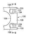
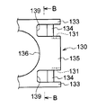
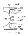
- the edge on the one end side of the second link member 130 is recessed in two directions toward the escape hole 136, in other words, in the direction toward the other end side, and is formed into a cut portion 139 parallel to each other.
- a portion between the two cut portions 139 is an inner ladder portion 135, and a portion outside each cut portion 139 is an outer ladder portion 133.
- a rotation pin 134 is formed between the outer ladder portion 133 and the inner ladder portion 135, in other words, between a pair of opposite side wall surfaces of the respective cut portions 139. ing.
- the second link member 130 is rotatably held on the back surface of the key top 110 by the rotation pin 134.
- An example of the engaging portion of the present invention is an inner surface of the outer ladder portion 133, in other words, a portion between the rotating pin 134 and the bottom surface of the notch portion 139 on the outer side wall surface of the notch portion 139.
- a certain recess 131 is formed. The recess 131 opens downward, in other words, toward the membrane sheet 160 (back sheet 170), but closes upward.
- the edge on the other end side of the second link member 130 is recessed in one direction toward the escape hole 136, in other words, toward the one end side.
- a sliding pin 132 is formed between a pair of opposing side wall surfaces of the recessed portion. The sliding pin 132 is inserted into the second holder 152 of the back plate 170 and is slidably held along the horizontal direction.
- a shaft hole 138 into which the rotation shaft 126 of the first link member 120 is fitted is formed at the center of the second link member 130.
- the first link member 120 and the second link member 130 are supported so as to be rotatable relative to each other when the rotating shaft 126 of the first link member 120 is fitted into the shaft hole 138 of the second link member 130.
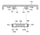
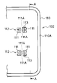
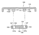
- a pair of rotation support portions 112 and a pair of slide support portions 114 are provided on the back surface of the key top 110.
- a pair of rotation support part 112 supports the rotation pin 134 of the 2nd link member 130 so that rotation is possible.
- the pair of slide support portions 114 support the slide pin 122 of the first link member 120 so that the slide pin 122 can be rotated and translated (slidable) in the horizontal direction (direction along the surface on the back side of the key top 110). .
- each of the rotation support portions 112 includes a pair of rotation support claws 111.
- a rotation support surface 111A which is a cylindrical concave surface having a radius of curvature matched to the outer peripheral surface of the rotation pin 134, is formed.
- a groove is formed on the surface of the support surface of the rotation pin 134 opposite to the side on which the rotation support surface 111A is formed. Therefore, the rotation support claw 111 has a U-shaped cross section that is recessed toward the rotation support surface 111A when viewed from below, in other words, a C-shaped cross section.
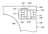
- the rotation support claw 111 near the slide support portion 114, in other words, the lower end portion of the outer side wall of the rotation support claw 111 on the key center side, A projection 113 that engages with the recess 131 of the second link member 130 is provided.
- the protrusion 113 is an example of the engaged portion of the present invention.
- the protrusion 113 has a wedge-shaped cross section that expands upward.
- FIGS. 5 and 8A in a state where the second link member 130 is assembled to the key top 110, the space between the inner side surface of the rotation support claw 111 and the inner ladder portion 135 of the second link member 130 is shown. In other words, a gap is formed between the inner side surface of the rotation support claw 111 and the side wall surface of the second link member 130 on the side opposite to the side where the recess 131 is formed.
- the key switch structure 100 of Embodiment 1 can be assembled along the following procedures. First, the second link member 130 is fitted inside the first link member 120, and the rotation shaft 126 of the first link member 120 is fitted into the shaft hole 138 of the second link member 130 to constitute the link mechanism 128.
- the rotation pin 124 of the first link member 120 in the link mechanism 128 is fitted into the first holder 150 of the back plate 170.
- the sliding pin 132 of the second link member 130 is fitted into the second holder 152 of the back plate 170.
- the rotation pin 134 When the rotation pin 134 is fitted into the rotation support portion 112 of the key top 110, the rotation pin 134 is inserted between the pair of rotation support claws 111 constituting the rotation support portion 112 and supported by the rotation support surface 111A.
- the protrusion 113 protrudes from the lower end portion of the outer surface of one of the pair of rotation support claws 111. For this reason, when the rotation pin 134 is inserted between the rotation support claws 111, the projection 113 interferes with the inner surface of the outer ladder portion 133 in the second link member 130, in other words, the outer surface of the cut portion 139.
- the rotation support claw 111 When the projection 113 of the rotation support claw 111 gets over the outer ladder 133, the rotation support claw 111 returns to the position before elastic deformation. As a result, the rotation pin 134 is fitted into the rotation support surface 111 ⁇ / b> A, and at the same time, the protrusion 113 engages with the recess 131 formed in the outer ladder 133.
- the rubber dome 140 urges the key top 110 in a direction away from the membrane sheet 160 (back plate 170). This urging force acts in a direction in which the crossing angle between the first link member 120 and the second link member 130 becomes large.
- the rotation pin 124 of the first link member 120 rotates inside the first holder 150 of the back plate 170.
- the rotation pin 134 of the second link member 130 rotates inside the rotation support portion 112 of the key top 110.
- the slide pin 122 of the first link member 120 slides horizontally in the direction away from the rotation pin 134 of the second link member 130 inside the slide support portion 114 of the key top 110.
- the sliding pin 132 of the second link member 130 slides horizontally in the direction away from the rotation pin 124 of the first link member 120 inside the second holder 152 of the back plate 170.
- the first link member 120 and the second link member 130 rotate in a direction in which the crossing angle becomes smaller as a whole. Therefore, the key top 110 moves toward the membrane sheet 160 (back plate 170) while maintaining a horizontal state, and compresses and deforms the rubber dome 140. And the contact pressing part 144 presses the contact part 166 of the membrane sheet 160, and it will be in a closed state as a switch.
- the key top 110 When the hand is released from the key top 110, the key top 110 is kept parallel by the link mechanism 128, and the height before pressing down in the direction away from the membrane sheet 160 (back plate 170) by the action of the rubber dome 140 and the link mechanism 128. Return. Then, the contact pressing part 144 is separated from the contact part 166 of the membrane sheet 160 and is opened as a switch (see FIG. 1).
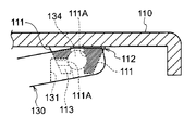
- the protrusion 113 of the rotation support claw 111 is fitted into the recess 131 provided in the outer ladder portion 133. .
- the upper surface 113 ⁇ / b> A of the protrusion 113 is in a state facing the ceiling surface 131 ⁇ / b> A of the recess 131. Therefore, when the key top 110 is lifted to some extent with respect to the link mechanism 128, the protrusion 113 is caught on the ceiling surface 131A of the recess 131, and the key top 110 cannot be lifted any more.
- the key top 110 is not easily detached from the link mechanism 128, specifically, the second link member 130. As a result, the key top 110 cannot be removed to the extent that a fingernail or the like is caught on the key top 110 when the key is pressed.
- the second link member 130 is connected to the outer surface of the rotation support claw 111 and the outer ladder portion 133 both when the key top 110 is raised and lowered. It rotates with respect to the rotation support claw 111 of the key top 110 while maintaining contact with the inner surface. As a result, the key top 110 is prevented from rotating with respect to the link mechanism 128.
- the rotation support claw 111 is thin because it has a U-shaped cross section, and even when the thickness of the ceiling of the key top 110 becomes thin, molding defects such as sink marks occur in the portion of the locking claw. Can be suppressed.
- the configurations of the back plate 170, the first holder 150, the second holder 152, the membrane sheet 160, the rubber dome 140, and the first link member 120 are the same as those of the key switch structure 100 of the first embodiment. Further, the configuration of the slide support portion 114 in the key top 110 is the same as that of the key switch structure 100 of the first embodiment.
- the recess 131 has a bottom surface of the notch 139 across the rotation pin 134 on the inner surface of the outer ladder 133. Is formed on the opposite side. In other words, the recess 131 is formed in a portion closer to the end than the rotation pin 134 on the outer side wall surface of the cut portion 139.
- the protrusion 113 to be fitted in the recess 131 is provided on the rotary claw 111 on the side close to the outer wall 110 ⁇ / b> A of the key top 110. In other words, the protrusion 113 is provided on the outer side wall of the rotation support claw 111 on the key peripheral side. And the protrusion 113 is made into the wedge shape which spreads upwards similarly to the key switch structure 100 of Embodiment 1.
- the second link member 130 has the same configuration as the second link member 130 in the key switch structure 100 of the first embodiment except for the above points.
- the assembly procedure of the key switch structure 102 is the same as that of the key switch structure 100 of the first embodiment.
- the rotation pin 134 of the second link member 130 is inserted between the rotation support claws 111 of the key top 110, the rotation support claw 111 on the key peripheral side is formed between the protrusion 113 and the outer ladder portion 133.
- the key switch structure 100 is the same as that of the key switch structure 100 of the first embodiment except that it is elastically deformed toward the inner ladder 135 of the second link member 130 due to mutual interference.
- a protrusion 113 is provided on the rotation support claw 111 on the key peripheral side in the rotation support portion 112.
- the recess 131 is provided on the inner surface of the outer ladder 133 of the second link member 130. Therefore, the key switch structure 102 has a vertical shift when the key top 110 is lifted by the claw as compared with the key switch structure 100 of the first embodiment in which the protrusion 113 is provided on the rotation support claw 111 on the key center side. However, it has the feature of being less.
- the configurations of the back plate 170, the first holder 150, the second holder 152, the membrane sheet 160, the rubber dome 140, and the first link member 120 are the same as those of the key switch structure 100 of the first embodiment. Further, the configuration of the slide support portion 114 in the key top 110 is the same as that of the key switch structure 100 of the first embodiment.
- the recess 131 is a portion between the rotation pin 134 on the side surface of the inner ladder portion 135 and the bottom surface of the cut surface 139. Is formed. In other words, the recess 131 is formed in a portion between the rotation pin 134 and the bottom surface of the cut surface 139 on the inner side wall surface of the cut portion 139.
- the protrusion 113 to be engaged with the recess 131 is provided on the inner surface of the rotation support claw 111 on the key center side of the key top 110.
- the protrusion 113 has a wedge shape that spreads upward as in the key switch structure 100 of the first embodiment.
- the second link member 130 has the same configuration as the second link member 130 in the key switch structure 100 of the first embodiment except for the above points.
- the assembly procedure of the key switch structure 104 is the same as that of the key switch structure 100 of the first embodiment.
- the rotation pin 134 of the second link member 130 is inserted between the rotation support claws 111 of the key top 110, the rotation support claw 111 on the key center side is formed between the protrusion 113 and the inner ladder 135.
- the key switch structure 100 is the same as that of the first embodiment except that the second link member 130 is elastically deformed in the direction toward the outer ladder 133 due to the mutual interference.
- a protrusion 113 is provided on the inner surface of the rotation support claw 111 on the key center side in the rotation support portion 112.
- the recess 131 is provided on the side surface of the inner ladder portion 135 of the second link member 130.
- the inner ladder 135 is less likely to be deformed than the outer ladder 133. Therefore, in the key switch structure 104 of the third embodiment, the key top 110 is linked to the key switch structure 100 of the first embodiment in which the protrusion 113 is provided on the outer side surface of the rotation support claw 111 on the key center side. It is difficult to disengage from the mechanism 128.
- Embodiment 4 a key switch structure 106 as a fourth example of the key switch structure of the present invention will be described with reference to the drawings.
- the recess 131 has a bottom surface of the notch 139 with respect to the rotation pin 134 on the side surface of the inner ladder 135 of the second link member 130. It is formed in the part on the opposite side.
- the protrusion 113 to be engaged with the recess 131 is provided on the inner surface of the rotation support claw 111 on the key peripheral side of the key top 110.
- the key switch structure 106 has the same configuration as the key switch structure 104 of the third embodiment.
- the protrusion 113 is provided on the rotation support claw 111 on the key peripheral side in the rotation support portion 112.
- the recessed part 131 is provided in the side surface of the inner ladder part 135 of the 2nd link member 130, ie, the side wall surface inside the notch part 139. Therefore, the key switch structure 106 has an up-down direction when the key top 110 is lifted by the claw, compared to the key switch structure 104 of the third embodiment in which the protrusion 113 is provided on the rotation support claw 111 on the key center side. However, it has the feature of being less.
- the key switch structure 108 is provided not only on the outer side surface of the rotation support claw 111 on the key center side but also on the inner side surface of the rotation support claw 111 on the key peripheral side.
- the projection 113 is provided in a projecting manner.
- a recess 131 is also formed in a portion of the insertion portion 139 opposite to the bottom surface.
- the portion where the recess 131 is provided faces inward with respect to the portion where the recess 131 is not provided with the rotation pin 134 as a boundary. In other words, it protrudes toward the inner ladder part 135. And the level
- the portion provided with the recess 131 on the inner side wall surface of the notch 139 faces outward with respect to the portion where the recess is not provided with the rotation pin 134 as a boundary, in other words, on the outer ladder portion 133. Protrusively. Similar to the outer side wall surface, a step is formed between a portion of the inner side wall portion where the concave portion 131 is provided and a portion where the concave portion 131 is not provided.
- the second link member has a crank shape that spreads toward the outer ladder portion 133.
- the surface opposite to the side on which the projection 113 of the rotation support claw 111 on the key center side and the rotation support claw 111 on the key peripheral side is provided.
- a gap is formed between the side wall surface of the cut portion 139 where the recess 131 is not provided.
- the key switch structure 108 has the same configuration as the key switch structure 100 of the first embodiment.
- the protrusion 113 is provided on each of the rotation support claws 111 on the key peripheral side and the key center side in the rotation support portion 112.
- a recess 131 is provided on both the inner surface of the outer ladder portion 133 and the side surface of the inner ladder portion 135 of the second link member 130. Therefore, the key switch structure 108 has a key top 110 that is different from the key switch structure in which the protrusion 113 is provided on one of the rotation support claw 111 on the key center side and the rotation support claw 111 on the key peripheral side. It has a feature that it is further difficult to come off from the link mechanism 128.
- the configurations of the back plate 170, the first holder 150, the second holder 152, the membrane sheet 160, the rubber dome 140, and the first link member 120 are the same as those of the key switch structure 100 of the first embodiment. Further, the configuration of the slide support portion 114 in the key top 110 is the same as that of the key switch structure 100 of the first embodiment.
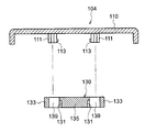
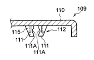
- a concave portion 115 as an example of an engaged portion is formed on the outer side surface of the rotation support claw 111 on the key center side. Yes. Therefore, the thickness d1 of the rotation support claw 111 on the key center side is larger by the depth of the recess 115 than the thickness d2 of the rotation support claw 111 on the key peripheral side.
- the recess 115 is open toward the slide support 114, in other words, toward the key center, but closed toward the back plate 170, that is, downward.
- a protrusion 137 is formed as an example of an engaging portion that engages with the recess 115 of the rotation support claw 111. As shown in FIG. 18, the protrusion 137 has a wedge shape that extends downward.
- the second link member 130 has the same configuration as the second link member 130 in the key switch structure 100 of Embodiment 1 except for the above points (see FIG. 17C).
- the assembly procedure of the key switch structure 109 is the same as that of the key switch structure 100 of the first embodiment.
- the rotation pin 134 of the second link member 130 is inserted between the rotation support claws 111 of the key top 110, due to the mutual interference between the protrusion 137 of the outer ladder 133 and the rotation support claw 111 on the key center side,
- the rotation support claws 111 on the key center side are deformed toward each other, in other words, toward the inner ladder 135, and the outer ladder 133 is elastically deformed outward.
- the recess 115 is closed downward, and the protrusion 137 has a wedge shape that extends downward.
- the protrusion 137 engages with the recess 115 of the rotation support claw 111.
- the bottom surface 137 ⁇ / b> A of the protrusion 137 shown in FIG. 18 is in a state facing the bottom surface 115 ⁇ / b> A of the recess 115. Therefore, when the key top 110 is lifted to some extent relative to the link mechanism 128, the protrusion 137 is caught on the bottom surface 115A of the recess 115 and cannot be lifted any further.
- the thickness d1 of the rotation support claw 111 on the key center side where the recess 115 is provided is larger than the thickness d2 of the rotation support claw 111 on the key center side in the key switch structure 100 of the first embodiment.
- the key switch structure of the sixth embodiment has a key top 110 having a link mechanism compared to a key switch structure in which the thickness of the rotation support claw on the key center side and the rotation support claw 111 on the key peripheral side is d2. It is hard to come off from 128.
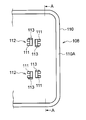
- the key switch structure 200 includes a key top 210, a link mechanism 228 configured to include a first link member 220 and a second link member 230, and a rubber dome as an elastic member. 240, the membrane sheet 260, and the back plate 270 to which the first holder 250 and the second holder 252 are attached.
- the first link member 220 and the second link member 230 correspond to one link member and another link member of the present invention.
- the back plate 270 is a plate made of a material having a certain degree of hardness and rigidity, such as a metal or a hard resin.
- the membrane sheet 260 has a structure in which two sheets on which a wiring pattern is printed with a spacer sheet (not shown) sandwiched therebetween, that is, an upper sheet and a lower sheet (not shown) are bonded to each other. It is made of a flexible material that is affixed to.
- the membrane sheet 260 is stuck on the back plate 270 such that the first holder 250 and the second holder 252 protrude from the holes 262 and 264, respectively.
- the holes 262 and 264 are formed in the membrane sheet 260 in accordance with the positions of the first holder 250 and the second holder 252.
- a contact portion 266 is provided at the center of the membrane sheet 260.
- a rubber dome 240 is fixed to the key top 210 on the contact portion 266 with an adhesive or the like.
- the rubber dome 240 is formed in a substantially cup shape using rubber or the like as a material, and has a fitting hole 242 in the upper center.
- a contact pressing portion 244 is formed to protrude toward the membrane sheet 260 at the center of the inner surface of the rubber dome 240.
- first link member 220, the second link member 230, and the link mechanism 228 will be described.
- first link member 220 and the second link member 230 have a nested structure in which the second link member 230 is fitted inside the first link member 220.
- the first link member 220 and the second link member 230 constitute a pantograph type link mechanism 228.
- the first link member 220 is a link member outside the link mechanism 228.
- the first link member 220 is formed on a frame body 221 formed in a substantially rectangular frame shape, a pair of rotating pins 224 formed on one end side of the frame body 221, and the other end side of the frame body 221.
- a pair of sliding pins 222 and a pair of rotating shafts 226 projecting inward from the center of the frame 221 are provided.
- the pair of rotating pins 224 are rotatably held on the back surface of the key top 210 (the membrane sheet 260, in other words, the surface facing the back sheet 270).
- the pair of sliding pins 222 is held slidably along the horizontal direction, in other words, along the surface direction of the membrane plate 260, at the sliding support portion 252 of the back plate 270.
- the second link member 230 is a link member inside the link mechanism 228.
- a circular escape hole 236 for escaping the rubber dome 240 is opened at the center of the second link member 230. Therefore, the second link member 230 has a frame shape as a whole.
- the edge on the one end side of the second link member 230 is recessed in two directions toward the escape hole 236, in other words, in the direction toward the other end side, and is formed as a cut portion 239 parallel to each other.
- a portion between the two cut portions 239 is an inner ladder portion 235, and a portion outside each cut portion 239 is an outer ladder portion 233. Therefore, the outer ladder portion 233 is formed at two locations, and the inner ladder portion 235 is formed at one location.
- a rotation pin 234 is formed between the outer ladder 233 and the inner ladder 235, respectively.
- the second link member 230 is rotatably held by the first holder 250 of the back plate 270 at the rotation pin 234.
- the edge on the other end side of the second link member 230 is recessed in one direction toward the escape hole 236, in other words, toward the one end side.
- a sliding pin 232 is formed between a pair of opposing side wall surfaces of the recessed portion. As will be described later, the sliding pin 232 is slidably held along the horizontal direction on the back surface of the key top 210.
- a shaft hole 238 into which the rotation shaft 226 of the first link member 220 is fitted is formed in the center portion of the second link member 230.
- the first link member 220 and the second link member 230 are rotatably supported by the rotation shaft 226 of the first link member 220 fitting into the shaft hole 238 of the second link member 230.
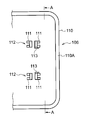
- a pair of rotation support portions 212 and a pair of slide support portions 214 are provided on the back surface of the key top 210.
- a pair of rotation support part 212 supports the rotation pin 224 of the 1st link member 230 so that rotation is possible.
- the pair of slide support portions 214 support the slide pin 232 of the second link member 230 so that the slide pin 232 can be rotated and translated (slidable) in the horizontal direction (the direction along the surface on the back side of the key top 210). .
- each of the rotation support portions 212 includes a pair of rotation support claws 211.
- a rotation support surface 211 ⁇ / b> A that is a cylindrical concave surface having a radius of curvature matched to the outer peripheral surface of the rotation pin 224 is formed.
- the rotation pin 224 is supported on the rotation support surface 211A.
- a groove is formed on the surface of the rotation support claw 211 opposite to the side on which the rotation support surface 211A is formed. For this reason, the rotation support claw 211 has a U-shaped cross section that is recessed toward the rotation support surface 211A as viewed from below, in other words, a C-shaped cross section.
- a protrusion 213 that engages with the recess 227 of the first link member 220 is provided at the lower end portion of the inner side wall of the rotation support claw 211 on the key peripheral side.
- the protrusion 213 has a wedge-shaped cross section that expands upward.
- the key switch structure 200 of the seventh embodiment can be assembled according to the same procedure as the key switch structure 100 of the first embodiment.
- the second link member 230 is fitted inside the first link member 220, and the rotation shaft 226 of the first link member 220 is fitted into the shaft hole 238 of the second link member 230 to constitute the link mechanism 228.
- the rotation pin 234 of the second link member 230 in the link mechanism 228 is fitted into the first holder 250 of the back plate 270.
- the sliding pin 222 of the first link member 220 is fitted into the second holder 252 of the back plate 270.
- the rotation pin 224 When the rotation pin 224 is fitted into the rotation support portion 212 of the key top 210, the rotation pin 224 is inserted between the pair of rotation support claws 211 constituting the rotation support portion 212 and is fitted between the rotation support surfaces 211A. .
- the rotation pin 224 since the protrusion 213 protrudes from the lower end portion of the inner surface of the rotation support claw 211 on the key peripheral side among the pair of rotation support claws 211, the rotation pin 224 is supported to rotate. When inserted between the claws 211, the protrusion 213 interferes with the outer surface of the frame 211 in the first link member 220.
- the rotation support claw 211 on the key center side and the rotation support claw 211 on the key peripheral side are elastically deformed in a direction in which the interval increases, and the rotation support claw 211 on the key peripheral side is separated from each other in other words.
- the elastic deformation is performed in a direction away from the one link member 220. Thereby, the protrusion 213 gets over the outer surface of the frame body 221.
- the rotation support claw 211 When the protrusion 213 of the rotation support claw 211 gets over the outer surface of the frame body 221, the rotation support claw 211 returns to the position before elastic deformation. Thereby, the rotation pin 224 is supported by the rotation support surface 211 ⁇ / b> A, and the protrusion 213 is engaged with the recess 227.
- the first link member 220 and the second link member 230 intersect with each other in an X shape to constitute a link mechanism 228.
- the link mechanism 228 is held by the back plate 170 at the sliding pin 222 of the first link member 220 and the rotating pin 234 of the second link member 230, and at the same time as the rotating pin 224 of the first link member 220 and the second pin 224.
- the key top 210 is held by the sliding pin 232 of the two link member 230.
- the rubber dome 240 biases the key top 210 in a direction away from the membrane sheet 260. This urging force acts in a direction in which the crossing angle between the first link member 220 and the second link member 230 becomes large.
- the sliding pin 222 of the first link member 220 slides in the direction away from the rotating pin 234 of the second link member 230 inside the sliding support portion 252 of the back plate 270. Further, the sliding pin 232 of the second link member 230 slides in the direction away from the rotating pin 224 of the first link member 220 inside the sliding support portion 214 of the key top 210. At the same time, the rotation pin 224 of the first link member 220 rotates inside the rotation support portion 212 of the key top 210. Further, the rotation pin 234 of the second link member 230 rotates inside the first holder 250 of the back plate 270.
- the first link member 220 and the second link member 230 rotate in a direction in which the crossing angle becomes smaller as a whole. Therefore, the key top 210 moves toward the membrane sheet 260 (back plate 270) while maintaining a horizontal state, and compresses and deforms the rubber dome 240. Then, the contact pressing part 244 presses the contact part 266 of the membrane sheet 260 to be closed as a switch.
- the key top 210 When the hand is released from the key top 210, the key top 210 is kept parallel by the link mechanism 228, and the height before being pressed in the direction away from the membrane sheet 260 (back plate 270) by the action of the rubber dome 240 and the link mechanism 228. It will return. Then, the contact pressing part 244 is separated from the contact part 266 of the membrane sheet 260 and is opened as a switch (see FIG. 19).
- the protrusion 213 of the rotation support claw 211 engages with the recess 227 of the first link member 220. Then, the upper surface of the protrusion 213 is in a state facing the ceiling surface of the recess 227. For this reason, if the key top 210 is lifted to a certain degree with respect to the link mechanism 228, the protrusion 213 is caught on the ceiling surface of the recess 237 and cannot be lifted any further. Therefore, even when the keyboard is thinned, the key top 210 is difficult to be detached from the link mechanism 228. As a result, the key top 210 cannot be removed to the extent that a fingernail or the like is caught on the key top 210 when the key is pressed.
- the rotation support claw 211 has a U-shaped cross section and is thin. For this reason, even when the thickness of the ceiling of the key top 210 is thin, it is possible to prevent molding defects such as sink marks from occurring in the portion of the locking claw.
Landscapes
- Push-Button Switches (AREA)
Abstract
The purpose of the present invention is to provide a key switch structure in which there is little decrease in the force of removal of the key top from the link mechanism, even when the keyboard is of a thin-type. This invention is provided with a link mechanism (128) for detachably supporting a key top (110) against a back sheet (170). The link mechanism (128) is provided with: a first link member (120), one end side of the first link member (120) being rotatably held at the obverse surface of the back plate (170), and the other end side of the first link member (120) being slidably held at the reverse surface of the key top (110); and a second link member (130) rotatably connected to the first link member (120), one end side of the second link member (130) engaging rotatably with a rotation support part (112) provided to the reverse surface of the key top (110) and the other end side of the second link member (130) being slidably held at the obverse surface of the back plate (170). A recess (131) is provided to the second link member (130), and a protrusion (113) is formed on the rotation support part (112), the protrusion (113) engaging with the recess (131) and restricting detachment of the key top (110) from the second link member (130).
Description
本発明はキースイッチ構造に関し、特に、情報処理機器、測定機器、医療機器、パーソナルコンピュータ、ワードプロセッサなどのキーボードに用いられるキースイッチ構造に関する。
The present invention relates to a key switch structure, and more particularly to a key switch structure used for a keyboard of an information processing device, a measuring device, a medical device, a personal computer, a word processor, or the like.
キーボードにおいては、キートップのどの部分を押下してもキートップが傾くことなく下降する所謂操作性を確保することが要求されている。そのような要求を満たすキースイッチ構造として、キートップと、キートップの下に設けられキートップを上下方向に案内するリンク機構と、を有するキースイッチ構造が開発された(例えば特許第4341733号公報を参照のこと)。
In the keyboard, it is required to ensure the so-called operability that the key top descends without tilting when any part of the key top is pressed. As a key switch structure that satisfies such requirements, a key switch structure having a key top and a link mechanism that is provided under the key top and guides the key top in the vertical direction has been developed (for example, Japanese Patent No. 4341733). checking).
上記キースイッチ構造においては、枠状に形成された外側のリンク部材と、同じく枠状に形成された内側のリンク部材と、をX字型に組み合わせてリンク機構が構成されている。そして、このリンク機構が、キートップとバックプレートとの間に設けられている。
In the key switch structure, a link mechanism is configured by combining an outer link member formed in a frame shape and an inner link member formed in a frame shape in an X shape. The link mechanism is provided between the key top and the back plate.
しかしながら、キースイッチ構造が上記の構造とされたキーボードにおいては、キーボードが薄型化された場合、キーボードの使用時、とくにキー押下時にキートップに指の爪等が引っ掛かると、キートップがリンク機構から外れ易いという問題があった。
However, in the keyboard having the key switch structure as described above, when the keyboard is thinned, when the keyboard is used, particularly when a fingernail is caught on the key top when the key is pressed, the key top is removed from the link mechanism. There was a problem that it was easy to come off.
本発明は、上記問題を解決すべく成されたもので、キートップがリンク機構から外れ難いキースイッチ構造の提供を目的とする。
The present invention has been made to solve the above-described problem, and an object of the present invention is to provide a key switch structure in which the key top is difficult to come off from the link mechanism.
本発明のある態様は、 押し下げられて接点を導通させるキートップの裏面に設けられた回転支持部に一端側が回動可能に係合し、他端側がバックプレートの表面を摺動可能に保持される一のリンク部材と、前記一のリンク部材と回動可能に連結されるとともに、一端側が前記バックプレートの表面に回動可能に保持され、他端側が前記キートップの裏面に摺動可能に保持される他のリンク部材と、を備え、前記キートップを前記バックプレートに対して接離可能に支持するリンク機構と、前記一のリンク部材に設けられた係合部と、前記回転支持部に形成され、前記係合部と係合して、前記キートップが前記一のリンク部材から外れるのを制限する被係合部と、を有するキースイッチ構造、を備える。
In one aspect of the present invention, one end side is rotatably engaged with the rotation support portion provided on the back surface of the key top that is pressed down to conduct the contact, and the other end side is slidably held on the surface of the back plate. One link member and the one link member are rotatably connected, one end side is rotatably held on the surface of the back plate, and the other end side is slidable on the back surface of the key top. Another link member to be held, a link mechanism that supports the key top so as to be capable of coming into contact with and separated from the back plate, an engagement portion provided in the one link member, and the rotation support portion And a key switch structure having an engaged portion that engages with the engaging portion and restricts the key top from being detached from the one link member.
上記態様では、キートップの裏面の回転支持部に回動可能に係合される一のリンク部材に係合部が、回転支持部に被係合部が設けられている。そして、一のリンク部材の係合部が回転支持部の被係合部に係合しているため、キートップをリンク機構に対して持ち上げてもキートップが前記リンク機構から外れ難い。
In the above aspect, the engagement portion is provided in one link member that is rotatably engaged with the rotation support portion on the back surface of the key top, and the engaged portion is provided in the rotation support portion. And since the engaging part of one link member is engaging with the to-be-engaged part of a rotation support part, even if it lifts a key top with respect to a link mechanism, a key top does not come off from the said link mechanism easily.
上記態様において、前記係合部が、前記一のリンク部材に形成され、前記バックプレート側が開口した凹部であり、前記被係合部が、前記回転支持部に形成され、前記開口から前記凹部に嵌る突起である。
In the above aspect, the engaging portion is a recess formed in the one link member, and the back plate side is open, and the engaged portion is formed in the rotation support portion, and the opening extends from the opening to the recess. It is a protrusion that fits.
上記態様では、係合部は、一のリンク部材に形成され、バックプレート側が開口した凹部である。一方、被係合部は、回転支持部に設けられ、前記凹部に嵌る突起である。
In the above aspect, the engaging portion is a recess formed in one link member and opened on the back plate side. On the other hand, the engaged portion is a protrusion that is provided in the rotation support portion and fits into the recess.
したがって、キートップをリンク機構に対して持ち上げても、凹部の開口していない側の壁に突起が掛かるので、キートップが一のリンク部材から外れ難い。
Therefore, even if the key top is lifted with respect to the link mechanism, a protrusion is applied to the wall on the side where the recess is not open, so that the key top is difficult to come off from one link member.
上記態様において、前記係合部が、前記一のリンク部材に形成された突起であり、前記被係合部が、前記回転支持部に形成され、前記バックプレート側が閉じているとともに、前記突起が嵌る凹部である。
In the above aspect, the engaging portion is a protrusion formed on the one link member, the engaged portion is formed on the rotation support portion, the back plate side is closed, and the protrusion is It is a recessed part to fit.
上記態様では、係合部は、一のリンク部材に形成された突起である。一方、被係合部は、回転支持部に設けられ、バックプレート側が閉じているとともに、前記突起が嵌る凹部である。したがって、キートップをリンク機構に対して持ち上げても、凹部のバックプレート側の壁に突起が掛かるので、キートップが一のリンク部材から外れ難い。
In the above aspect, the engaging portion is a protrusion formed on one link member. On the other hand, the engaged portion is a recess provided in the rotation support portion, the back plate side being closed, and the projection being fitted therein. Therefore, even if the key top is lifted with respect to the link mechanism, the protrusion is applied to the wall on the back plate side of the recess, so that the key top is difficult to come off from one link member.
上記態様において、前記一のリンク部材の一端側には回転ピンが形成されているとともに、前記回転支持部は、前記回転ピンを支承する凹陥面である回転支持面が互いに対向する側の面に形成された一対の回転支持爪を有し、前記凹部は、前記一のリンク部材における前記回転ピンの近傍に形成され、前記突起は、前記回転支持爪に形成されている。
In the above aspect, a rotation pin is formed on one end side of the one link member, and the rotation support portion has a rotation support surface that is a concave surface that supports the rotation pin on a surface on a side facing each other. It has a pair of formed rotation support claws, the recess is formed in the vicinity of the rotation pin in the one link member, and the projection is formed in the rotation support claw.
上記態様では、一のリンク部材の回転ピンを一対の回転支持爪の間に挿入すると、回転支持爪が互いに広がる方向に弾性変形して、回転ピンが凹陥面に支承される。そして、一のリンク部材に形成された凹部には回転支持爪に形成された突起が嵌入する。したがって、回転ピンを凹陥面に支承されるまで回転支持爪の間に圧入するだけで、一のリンク部材を回転支持部に装着できる。
In the above aspect, when the rotation pin of one link member is inserted between the pair of rotation support claws, the rotation support claws are elastically deformed in the direction in which the rotation pins spread to each other, and the rotation pin is supported on the recessed surface. And the protrusion formed in the rotation support nail | claw fits in the recessed part formed in the one link member. Therefore, the one link member can be mounted on the rotation support portion only by press-fitting the rotation pin between the rotation support claws until the rotation pin is supported by the recessed surface.
上記態様において、前記一のリンク部材の一端側には回転ピンが形成されているとともに、前記回転支持部は、前記回転ピンを支承する凹陥面である回転支持面が互いに対向する側の面に形成された一対の回転支持爪を有し、前記突起は、前記一のリンク部材における前記回転ピンの近傍に形成され、前記凹部は、前記回転支持爪に形成されている。
In the above aspect, a rotation pin is formed on one end side of the one link member, and the rotation support portion has a rotation support surface that is a concave surface that supports the rotation pin on a surface on a side facing each other. A pair of rotation support claws are formed, the protrusion is formed in the vicinity of the rotation pin in the one link member, and the recess is formed in the rotation support claw.
上記態様では、一のリンク部材の回転ピンを一対の回転支持爪の間に挿入すると、回転支持爪が互いに広がる方向に弾性変形して、回転ピンが凹陥面に支承される。そして、一のリンク部材の突起が回転支持爪の凹部に嵌入する。したがって、回転ピンを凹陥面に支承されるまで回転支持爪の間に圧入するだけで、一のリンク部材をキートップ裏面の回転支持部に装着できる。
In the above aspect, when the rotation pin of one link member is inserted between the pair of rotation support claws, the rotation support claws are elastically deformed in the direction in which the rotation pins spread to each other, and the rotation pin is supported on the recessed surface. And the protrusion of one link member is inserted in the recess of the rotation support claw. Therefore, the one link member can be attached to the rotation support portion on the back surface of the key top by simply press-fitting the rotation pin between the rotation support claws until the rotation pin is supported on the concave surface.
上記態様において、前記回転支持爪の前記凹陥面が形成された側とは反対側の面に溝が形成されている。
In the above aspect, a groove is formed on the surface of the rotation support claw opposite to the side on which the recessed surface is formed.
上記態様では、回転支持爪における凹陥面が形成された側とは反対側の面に溝を形成することにより、回転支持爪が薄肉とされている。このため、キートップの上面の板厚が薄くなった場合においても、回転支持爪を形成した部分にヒケなどの成形不良が生じるのを防止できる。
In the above aspect, the rotation support claw is thin by forming a groove on the surface of the rotation support claw opposite to the side where the concave surface is formed. For this reason, even when the thickness of the upper surface of the key top is reduced, it is possible to prevent molding defects such as sink marks from occurring in the portion where the rotation support claw is formed.
以上説明したように、本発明によれば、キートップがリンク機構から外れ難いキースイッチ構造が提供される。
As described above, according to the present invention, there is provided a key switch structure in which the key top is not easily detached from the link mechanism.
1.実施形態1
以下、図面を参照して本発明のキースイッチ構造の第1の例であるキースイッチ構造100について説明する。
(構成)
図1~図4に示すように、キースイッチ構造100は、キートップ110と、第1リンク部材120と第2リンク部材130とを含んで構成されるリンク機構128と、弾性部材の一例としてのラバードーム140と、メンブレンシート160と、第1ホルダ150及び第2ホルダ152が取り付けられたバックプレート170と、を含んで構成されている。ここで、第1リンク部材120は本発明の他のリンク部材であり、第2リンク部材130は本発明の一のリンク部材である。 1. Embodiment 1
Hereinafter, akey switch structure 100 which is a first example of a key switch structure of the present invention will be described with reference to the drawings.
(Constitution)
As shown in FIGS. 1 to 4, thekey switch structure 100 includes a key top 110, a link mechanism 128 including a first link member 120 and a second link member 130, and an example of an elastic member. The rubber dome 140, the membrane sheet 160, and the back plate 170 to which the first holder 150 and the second holder 152 are attached are configured. Here, the first link member 120 is another link member of the present invention, and the second link member 130 is one link member of the present invention.
以下、図面を参照して本発明のキースイッチ構造の第1の例であるキースイッチ構造100について説明する。
(構成)
図1~図4に示すように、キースイッチ構造100は、キートップ110と、第1リンク部材120と第2リンク部材130とを含んで構成されるリンク機構128と、弾性部材の一例としてのラバードーム140と、メンブレンシート160と、第1ホルダ150及び第2ホルダ152が取り付けられたバックプレート170と、を含んで構成されている。ここで、第1リンク部材120は本発明の他のリンク部材であり、第2リンク部材130は本発明の一のリンク部材である。 1. Embodiment 1
Hereinafter, a
(Constitution)
As shown in FIGS. 1 to 4, the
バックプレート170は、金属製あるいは硬質の樹脂製など、ある程度の硬度と剛性を備えた素材で形成された板材である。メンブレンシート160は、スペーサシート160Bを挟んで配線パターンが印刷された上部シート160Aと下部シート160Cとが貼合された構成とされている。さらに、メンブレンシート160は、バックプレート170の表面に貼付される柔軟な素材で形成されている。
The back plate 170 is a plate made of a material having a certain degree of hardness and rigidity, such as a metal or a hard resin. The membrane sheet 160 is configured such that an upper sheet 160A on which a wiring pattern is printed and a lower sheet 160C are bonded with a spacer sheet 160B interposed therebetween. Further, the membrane sheet 160 is formed of a flexible material that is attached to the surface of the back plate 170.
図2~図4に示すように、メンブレンシート160には、第1ホルダ150、第2ホルダ152の位置に合わせて穴162、164が形成されている。そして、メンブレンシート160は、穴162、164からそれぞれ第1ホルダ150、第2ホルダ152を突出させた状態で、バックプレート170上に貼付されている。
2 to 4, holes 162, 164 are formed in the membrane sheet 160 in accordance with the positions of the first holder 150 and the second holder 152. The membrane sheet 160 is stuck on the back plate 170 with the first holder 150 and the second holder 152 protruding from the holes 162 and 164, respectively.
図1に示すように、メンブレンシート160の中央には接点部166が設けられている。接点部166は、上部シート160Aに設けられた上部接点166Aと下部シート160Cに設けられた下部接点166Bとからなる。この接点部166上において、メンブレンシート160とキートップ110との間にラバードーム140が接着剤などで固定されている。ラバードーム140は、ゴム等を素材として略カップ状に形成され、上部中央に嵌合穴142を有している。さらに、ラバードーム140の内面の中央部には、接点押下部144がメンブレンシート160に向けて突出形成されている。
As shown in FIG. 1, a contact portion 166 is provided at the center of the membrane sheet 160. The contact portion 166 includes an upper contact 166A provided on the upper sheet 160A and a lower contact 166B provided on the lower sheet 160C. On the contact portion 166, the rubber dome 140 is fixed between the membrane sheet 160 and the key top 110 with an adhesive or the like. The rubber dome 140 is formed in a substantially cup shape using rubber or the like as a material, and has a fitting hole 142 in the upper center. Further, a contact pressing portion 144 is formed to protrude toward the membrane sheet 160 at the center of the inner surface of the rubber dome 140.
キートップ110が押下されることにより、キートップ110は、後述するリンク機構128の作用によってメンブレンシート160(バックプレート170)に向けて平行を保ちながら移動する。そして、ラバードーム140が圧縮変形すると共に、内部に形成されている接点押下部144が、メンブレンシート160の接点部166が設けられた部分を押圧する。
When the key top 110 is pressed, the key top 110 moves while maintaining parallel to the membrane sheet 160 (back plate 170) by the action of a link mechanism 128 described later. The rubber dome 140 is compressed and deformed, and the contact pressing portion 144 formed inside presses the portion of the membrane sheet 160 where the contact portion 166 is provided.
メンブレンシート160の接点部166の部分が押圧されると、上部接点166Aと下部接点166Bとが接触して電気的に接続され、スイッチとして閉成状態となる。
When the portion of the contact portion 166 of the membrane sheet 160 is pressed, the upper contact 166A and the lower contact 166B come into contact with each other and are electrically connected to be in a closed state as a switch.
キートップ110の押下を解除すると、各構成部品は、ラバードーム140とメンブレンシート160との復元力(弾性)によって元の状態に戻る。そして、メンブレンシート160の接点部166が接触を失い、電気的接触が絶たれるため、スイッチは開放状態となる。
When the pressing of the key top 110 is released, each component returns to the original state by the restoring force (elasticity) of the rubber dome 140 and the membrane sheet 160. And since the contact part 166 of the membrane sheet 160 loses a contact and an electrical contact is cut | disconnected, a switch will be in an open state.
以下、第1リンク部材120と第2リンク部材130とリンク機構128とについて説明する。図3に示すように、第1リンク部材120と第2リンク部材130とは、第1リンク部材120の内側に第2リンク部材130が嵌り込む入れ子構造となっている。そして、これら第1リンク部材120と第2リンク部材130とで、パンタグラフ方式のリンク機構128が構成されている。
Hereinafter, the first link member 120, the second link member 130, and the link mechanism 128 will be described. As shown in FIG. 3, the first link member 120 and the second link member 130 have a nested structure in which the second link member 130 is fitted inside the first link member 120. The first link member 120 and the second link member 130 constitute a pantograph type link mechanism 128.
図2~図5に示すように、第1リンク部材120は、リンク機構128の外側のリンク部材であって、略矩形枠状に形成された枠体121と、一対の回転ピン124と、一対の摺動ピン122と、一対の回転軸126と、を備える。一対の回転ピン124は、枠体121の一端側に形成され、バックプレート170の第1ホルダ150に挿入されて回動可能に保持される。一対の摺動ピン122は、枠体121の他端側に形成され、キートップ110の裏側(メンブレンシート160に対向する側)の面において水平方向、言い換えればメンブレンシート160の面方向に沿ってスライド可能に保持される。一対の回転軸126は、枠体121の中央部から内側に突出している。
As shown in FIGS. 2 to 5, the first link member 120 is a link member outside the link mechanism 128 and includes a frame body 121 formed in a substantially rectangular frame shape, a pair of rotating pins 124, and a pair of The sliding pin 122 and a pair of rotating shafts 126 are provided. The pair of rotation pins 124 is formed on one end side of the frame body 121 and is inserted into the first holder 150 of the back plate 170 and held rotatably. The pair of sliding pins 122 are formed on the other end side of the frame body 121, and in the horizontal direction on the back side (side facing the membrane sheet 160) of the key top 110, in other words, along the surface direction of the membrane sheet 160. Holds slidable. The pair of rotating shafts 126 protrudes inward from the center portion of the frame body 121.
図2~図5に示すように、第2リンク部材130は、リンク機構128の内側のリンク部材であって、中央部には、ラバードーム140を逃げるための円形状の逃げ孔136が開口している。したがって、第2リンク部材130もまた、全体として枠体状とされている。
As shown in FIGS. 2 to 5, the second link member 130 is a link member inside the link mechanism 128, and a circular escape hole 136 for escaping the rubber dome 140 is opened at the center. ing. Therefore, the second link member 130 also has a frame shape as a whole.
第2リンク部材130の一端側の端縁は、2箇所において逃げ孔136に向かう方向、言い換えれば他端側に向かう方向に凹陥して互いに平行な切込部139とされている。そして、2つの切込部139の間の部分は内梯部135とされ、それぞれの切込部139の外側の部分は外梯部133とされている。
The edge on the one end side of the second link member 130 is recessed in two directions toward the escape hole 136, in other words, in the direction toward the other end side, and is formed into a cut portion 139 parallel to each other. A portion between the two cut portions 139 is an inner ladder portion 135, and a portion outside each cut portion 139 is an outer ladder portion 133.
図2~図8に示すように、外梯部133と内梯部135との間、言い換えればそれぞれの切込部139の互いに対向する一対の側壁面の間には、回転ピン134が形成されている。そして、後述するように、第2リンク部材130は、回転ピン134においてキートップ110の裏面で回動可能に保持されている。そして、外梯部133の内側の面、言い換えれば切込部139の外側の側壁面における回転ピン134と切込部139の底面との間の部分には、本発明の係合部の一例である凹部131が形成されている。凹部131は、下方、換言すればメンブレンシート160(バックシート170)に向かって開口しているが、上方に向かっては閉じている。
As shown in FIGS. 2 to 8, a rotation pin 134 is formed between the outer ladder portion 133 and the inner ladder portion 135, in other words, between a pair of opposite side wall surfaces of the respective cut portions 139. ing. As will be described later, the second link member 130 is rotatably held on the back surface of the key top 110 by the rotation pin 134. An example of the engaging portion of the present invention is an inner surface of the outer ladder portion 133, in other words, a portion between the rotating pin 134 and the bottom surface of the notch portion 139 on the outer side wall surface of the notch portion 139. A certain recess 131 is formed. The recess 131 opens downward, in other words, toward the membrane sheet 160 (back sheet 170), but closes upward.
一方、第2リンク部材130の他端側の端縁は、1箇所において逃げ孔136に向かう方向、言い換えれば一端側に向かう方向に凹陥している。そして、前記凹陥部の互いに対向する一対の側壁面の間には、摺動ピン132が形成されている。摺動ピン132は、バックプレート170の第2ホルダ152に挿入されて水平方向に沿って摺動可能に保持される。
On the other hand, the edge on the other end side of the second link member 130 is recessed in one direction toward the escape hole 136, in other words, toward the one end side. A sliding pin 132 is formed between a pair of opposing side wall surfaces of the recessed portion. The sliding pin 132 is inserted into the second holder 152 of the back plate 170 and is slidably held along the horizontal direction.
図2~図5に示すように、第2リンク部材130の中央部には、第1リンク部材120の回転軸126が嵌り込む軸穴138が形成されている。第1リンク部材120と第2リンク部材130とは、第1リンク部材120の回転軸126が第2リンク部材130の軸穴138に嵌り込むことによって互いに回動可能に支持される。
As shown in FIGS. 2 to 5, a shaft hole 138 into which the rotation shaft 126 of the first link member 120 is fitted is formed at the center of the second link member 130. The first link member 120 and the second link member 130 are supported so as to be rotatable relative to each other when the rotating shaft 126 of the first link member 120 is fitted into the shaft hole 138 of the second link member 130.
図1~図5に示すように、キートップ110の裏側の面には、一対の回転支持部112と、一対のスライド支持部114と、が設けられている。一対の回転支持部112は、第2リンク部材130の回転ピン134を回動可能に支持する。一対のスライド支持部114は、第1リンク部材120の摺動ピン122を回動可能にかつ水平方向(キートップ110の裏側の面に沿った方向)に平行移動(摺動)可能に支持する。
As shown in FIG. 1 to FIG. 5, a pair of rotation support portions 112 and a pair of slide support portions 114 are provided on the back surface of the key top 110. A pair of rotation support part 112 supports the rotation pin 134 of the 2nd link member 130 so that rotation is possible. The pair of slide support portions 114 support the slide pin 122 of the first link member 120 so that the slide pin 122 can be rotated and translated (slidable) in the horizontal direction (direction along the surface on the back side of the key top 110). .
図1~図8に示すように、回転支持部112は、それぞれ一対の回転支持爪111を備える。回転支持爪111における回転ピン134の支承面には、回転ピン134の外周面に合わせた曲率半径を有する円筒面状の凹陥面である回転支持面111Aが形成されている。さらに、回転ピン134の支承面で回転支持面111Aが形成された側とは反対側の面には、溝が形成されている。したがって、回転支持爪111は、下方から見ると回転支持面111Aに向かって凹陥するU字型断面、言い換えればC字型断面を有している。
As shown in FIGS. 1 to 8, each of the rotation support portions 112 includes a pair of rotation support claws 111. On the support surface of the rotation pin 134 in the rotation support claw 111, a rotation support surface 111A, which is a cylindrical concave surface having a radius of curvature matched to the outer peripheral surface of the rotation pin 134, is formed. Further, a groove is formed on the surface of the support surface of the rotation pin 134 opposite to the side on which the rotation support surface 111A is formed. Therefore, the rotation support claw 111 has a U-shaped cross section that is recessed toward the rotation support surface 111A when viewed from below, in other words, a C-shaped cross section.
図1~図8に示すように、一対の回転支持爪111のうち、スライド支持部114寄りの回転支持爪111、換言すればキー中心側の回転支持爪111における外側の側壁の下端部には、第2リンク部材130の凹部131と係合する突起113が設けられている。突起113は、本発明の被係合部の一例である。突起113は、上方に向かって拡大する楔状の断面を有している。
As shown in FIGS. 1 to 8, of the pair of rotation support claws 111, the rotation support claw 111 near the slide support portion 114, in other words, the lower end portion of the outer side wall of the rotation support claw 111 on the key center side, A projection 113 that engages with the recess 131 of the second link member 130 is provided. The protrusion 113 is an example of the engaged portion of the present invention. The protrusion 113 has a wedge-shaped cross section that expands upward.
したがって、第2リンク部材130の回転ピン134を一対の回転支持爪111の間に挿入して回転支持面11Aで支承された状態とすると、図5、図7、図8A、及び図8Bに示すように、回転支持爪111の突起113が第2リンク部材130の凹部131に嵌り込む。
Therefore, when the rotation pin 134 of the second link member 130 is inserted between the pair of rotation support claws 111 and supported by the rotation support surface 11A, it is shown in FIGS. 5, 7, 8A, and 8B. As described above, the protrusion 113 of the rotation support claw 111 is fitted into the recess 131 of the second link member 130.
また、図5および図8Aに示したように、第2リンク部材130をキートップ110に組み付けた状態において、回転支持爪111の内側の側面と第2リンク部材130の内梯部135との間、言い換えれば、回転支持爪111の内側の側面と第2リンク部材130における切込部139の凹部131が形成された側とは反対側の側壁面との間には、隙間が形成される。
Further, as shown in FIGS. 5 and 8A, in a state where the second link member 130 is assembled to the key top 110, the space between the inner side surface of the rotation support claw 111 and the inner ladder portion 135 of the second link member 130 is shown. In other words, a gap is formed between the inner side surface of the rotation support claw 111 and the side wall surface of the second link member 130 on the side opposite to the side where the recess 131 is formed.
(キースイッチ構造の組み立て手順)
実施形態1のキースイッチ構造100は、以下の手順に沿って組み立てることができる。先ず、第1リンク部材120の内側に第2リンク部材130を嵌め込み、第1リンク部材120の回転軸126を第2リンク部材130の軸穴138に嵌めこんでリンク機構128を構成する。 (Key switch structure assembly procedure)
Thekey switch structure 100 of Embodiment 1 can be assembled along the following procedures. First, the second link member 130 is fitted inside the first link member 120, and the rotation shaft 126 of the first link member 120 is fitted into the shaft hole 138 of the second link member 130 to constitute the link mechanism 128.
実施形態1のキースイッチ構造100は、以下の手順に沿って組み立てることができる。先ず、第1リンク部材120の内側に第2リンク部材130を嵌め込み、第1リンク部材120の回転軸126を第2リンク部材130の軸穴138に嵌めこんでリンク機構128を構成する。 (Key switch structure assembly procedure)
The
次いで、リンク機構128における第1リンク部材120の回転ピン124をバックプレート170の第1ホルダ150に嵌め込む。そして、第2リンク部材130の摺動ピン132をバックプレート170の第2ホルダ152に嵌め込む。
Next, the rotation pin 124 of the first link member 120 in the link mechanism 128 is fitted into the first holder 150 of the back plate 170. Then, the sliding pin 132 of the second link member 130 is fitted into the second holder 152 of the back plate 170.
最後に、第2リンク部材130の回転ピン134をキートップ110の回転支持部112に嵌め込むとともに、第1リンク部材120の摺動ピン122をスライド支持部114に嵌め込む。
Finally, the rotation pin 134 of the second link member 130 is fitted into the rotation support portion 112 of the key top 110 and the slide pin 122 of the first link member 120 is fitted into the slide support portion 114.
回転ピン134をキートップ110の回転支持部112に嵌め込むと、回転ピン134は、回転支持部112を構成する一対の回転支持爪111の間に挿入され、回転支持面111Aで支承される。
When the rotation pin 134 is fitted into the rotation support portion 112 of the key top 110, the rotation pin 134 is inserted between the pair of rotation support claws 111 constituting the rotation support portion 112 and supported by the rotation support surface 111A.
前述のように、一対の回転支持爪111のうち、一方における外側の面の下端部には突起113が突設されている。このため、回転ピン134を回転支持爪111の間に挿入すると、突起113が第2リンク部材130における外梯部133の内側の面、言い換えれば切込部139の外側の面と干渉する。
As described above, the protrusion 113 protrudes from the lower end portion of the outer surface of one of the pair of rotation support claws 111. For this reason, when the rotation pin 134 is inserted between the rotation support claws 111, the projection 113 interferes with the inner surface of the outer ladder portion 133 in the second link member 130, in other words, the outer surface of the cut portion 139.
しかしながら、図5および図8Aに示すように、回転支持爪111の内側の面と第2リンク部材130の内梯部135との間には隙間がある。これにより、キー中心側の回転支持爪111とキー周縁側の回転支持爪111とは、互いに間隔が広がる方向に変形する。さらに、キー中心側の回転支持爪は、互いに近接する方向に、換言すれば第2リンク部材130における内梯部135に向かって弾性変形する。これにより、突起113が外梯部133の内側の面を乗り越える。
However, as shown in FIGS. 5 and 8A, there is a gap between the inner surface of the rotation support claw 111 and the inner ladder portion 135 of the second link member 130. Thereby, the rotation support claw 111 on the key center side and the rotation support claw 111 on the key peripheral side are deformed in a direction in which the interval increases. Further, the rotation support pawls on the key center side are elastically deformed toward each other, in other words, toward the inner ladder portion 135 of the second link member 130. Thereby, the protrusion 113 gets over the inner surface of the outer ladder part 133.
回転支持爪111の突起113が外梯部133を乗り越えると、回転支持爪111は弾性変形前の位置に戻る。これにより、回転ピン134が回転支持面111Aに嵌め込まれると同時に、突起113が外梯部133に形成された凹部131と係合する。
When the projection 113 of the rotation support claw 111 gets over the outer ladder 133, the rotation support claw 111 returns to the position before elastic deformation. As a result, the rotation pin 134 is fitted into the rotation support surface 111 </ b> A, and at the same time, the protrusion 113 engages with the recess 131 formed in the outer ladder 133.
(作用)
図3に示すように、実施形態1のキースイッチ構造100においては、第1リンク部材120と第2リンク部材130とがX字型に交差してリンク機構128を構成している。このため、前述のように、リンク機構128は、第1リンク部材120の回転ピン124と第2リンク部材130の摺動ピン132とにおいてバックプレート170に保持される。さらに、リンク機構128は、第1リンク部材120の摺動ピン122と第2リンク部材130の回転ピン134とにおいてキートップ110に保持される。 (Action)
As shown in FIG. 3, in thekey switch structure 100 of the first embodiment, the first link member 120 and the second link member 130 intersect with each other in an X shape to form a link mechanism 128. Therefore, as described above, the link mechanism 128 is held by the back plate 170 at the rotation pin 124 of the first link member 120 and the sliding pin 132 of the second link member 130. Further, the link mechanism 128 is held on the key top 110 by the sliding pin 122 of the first link member 120 and the rotation pin 134 of the second link member 130.
図3に示すように、実施形態1のキースイッチ構造100においては、第1リンク部材120と第2リンク部材130とがX字型に交差してリンク機構128を構成している。このため、前述のように、リンク機構128は、第1リンク部材120の回転ピン124と第2リンク部材130の摺動ピン132とにおいてバックプレート170に保持される。さらに、リンク機構128は、第1リンク部材120の摺動ピン122と第2リンク部材130の回転ピン134とにおいてキートップ110に保持される。 (Action)
As shown in FIG. 3, in the
通常状態(キートップ110を押下していない状態)では、ラバードーム140は、キートップ110を、メンブレンシート160(バックプレート170)から離れる方向へ付勢している。この付勢力は、第1リンク部材120と第2リンク部材130との交差角度が大となる方向へ作用する。
In a normal state (a state where the key top 110 is not pressed), the rubber dome 140 urges the key top 110 in a direction away from the membrane sheet 160 (back plate 170). This urging force acts in a direction in which the crossing angle between the first link member 120 and the second link member 130 becomes large.
キートップ110を押下すると、第1リンク部材120の回転ピン124が、バックプレート170の第1ホルダ150の内部で回転する。そして、第2リンク部材130の回転ピン134が、キートップ110の回転支持部112の内側で回転する。さらに、第1リンク部材120の摺動ピン122が、キートップ110のスライド支持部114の内側において、第2リンク部材130の回転ピン134から遠ざかる方向に向かって水平に摺動する。同時に、第2リンク部材130の摺動ピン132は、バックプレート170の第2ホルダ152の内部において、第1リンク部材120の回転ピン124から遠ざかる方向に向かって水平に摺動する。
When the key top 110 is pressed, the rotation pin 124 of the first link member 120 rotates inside the first holder 150 of the back plate 170. Then, the rotation pin 134 of the second link member 130 rotates inside the rotation support portion 112 of the key top 110. Further, the slide pin 122 of the first link member 120 slides horizontally in the direction away from the rotation pin 134 of the second link member 130 inside the slide support portion 114 of the key top 110. At the same time, the sliding pin 132 of the second link member 130 slides horizontally in the direction away from the rotation pin 124 of the first link member 120 inside the second holder 152 of the back plate 170.
これによって、第1リンク部材120と第2リンク部材130とは、全体として交差角度が小さくなる方向に回転する。このため、キートップ110は、水平状態を保ちながらメンブレンシート160(バックプレート170)に向けて移動してラバードーム140を圧縮変形させる。そして、接点押下部144がメンブレンシート160の接点部166を押圧して、スイッチとして閉成状態となる。
Thereby, the first link member 120 and the second link member 130 rotate in a direction in which the crossing angle becomes smaller as a whole. Therefore, the key top 110 moves toward the membrane sheet 160 (back plate 170) while maintaining a horizontal state, and compresses and deforms the rubber dome 140. And the contact pressing part 144 presses the contact part 166 of the membrane sheet 160, and it will be in a closed state as a switch.
キートップ110から手を離すと、キートップ110は、リンク機構128によって平行を保ちながら、ラバードーム140及びリンク機構128の作用によってメンブレンシート160(バックプレート170)から離れる方向に押下前の高さまで復帰する。そして、接点押下部144は、メンブレンシート160の接点部166から離間して、スイッチとしては開放状態となる(図1参照)。
When the hand is released from the key top 110, the key top 110 is kept parallel by the link mechanism 128, and the height before pressing down in the direction away from the membrane sheet 160 (back plate 170) by the action of the rubber dome 140 and the link mechanism 128. Return. Then, the contact pressing part 144 is separated from the contact part 166 of the membrane sheet 160 and is opened as a switch (see FIG. 1).
一方、第2リンク部材130の回転ピン134がキートップ110の回転支持部112に填め込まれた状態においては、回転支持爪111の突起113が外梯部133に設けられた凹部131に嵌り込む。そして、図7に示すように、突起113の上面113Aが凹部131の天井面131Aに相対する状態となる。したがって、リンク機構128に対してキートップ110をある程度持ち上げると、突起113が凹部131の天井面131Aに引っ掛かり、キートップ110はそれ以上持ち上がらなくなる。故に、キーボードが薄型化された場合においても、キートップ110はリンク機構128、具体的には第2リンク部材130から外れ難くなる。これにより、キー押下時にキートップ110に指の爪等が引っ掛かった程度では、キートップ110は外れなくなる。
On the other hand, in a state where the rotation pin 134 of the second link member 130 is fitted in the rotation support portion 112 of the key top 110, the protrusion 113 of the rotation support claw 111 is fitted into the recess 131 provided in the outer ladder portion 133. . Then, as shown in FIG. 7, the upper surface 113 </ b> A of the protrusion 113 is in a state facing the ceiling surface 131 </ b> A of the recess 131. Therefore, when the key top 110 is lifted to some extent with respect to the link mechanism 128, the protrusion 113 is caught on the ceiling surface 131A of the recess 131, and the key top 110 cannot be lifted any more. Therefore, even when the keyboard is thinned, the key top 110 is not easily detached from the link mechanism 128, specifically, the second link member 130. As a result, the key top 110 cannot be removed to the extent that a fingernail or the like is caught on the key top 110 when the key is pressed.
また、図8Aに示すように、回転支持爪111の外側の面と外梯部133の内側の面との間には殆ど隙間がない。このため、図8Bにおいて斜線を付した部分が示すように、キートップ110が上昇するときも下降するときも、第2リンク部材130は、回転支持爪111の外側の面と外梯部133の内側の面とが接触を保った状態でキートップ110の回転支持爪111に対して回転する。これにより、キートップ110がリンク機構128に対して回転することが抑止される。
Further, as shown in FIG. 8A, there is almost no gap between the outer surface of the rotation support claw 111 and the inner surface of the outer ladder 133. For this reason, as shown by the hatched portion in FIG. 8B, the second link member 130 is connected to the outer surface of the rotation support claw 111 and the outer ladder portion 133 both when the key top 110 is raised and lowered. It rotates with respect to the rotation support claw 111 of the key top 110 while maintaining contact with the inner surface. As a result, the key top 110 is prevented from rotating with respect to the link mechanism 128.
また、回転支持爪111は、U字型断面とされているから薄肉であり、キートップ110の天井の肉が薄くなった場合においても係止爪の部分にヒケなどの成形不良が生じることを抑止できる。
Further, the rotation support claw 111 is thin because it has a U-shaped cross section, and even when the thickness of the ceiling of the key top 110 becomes thin, molding defects such as sink marks occur in the portion of the locking claw. Can be suppressed.
2.実施形態2
以下、図面を参照して本発明のキースイッチ構造の第2の例であるキースイッチ構造102について説明する。 2. Embodiment 2
Hereinafter, akey switch structure 102 as a second example of the key switch structure of the present invention will be described with reference to the drawings.
以下、図面を参照して本発明のキースイッチ構造の第2の例であるキースイッチ構造102について説明する。 2. Embodiment 2
Hereinafter, a
(構成)
キースイッチ構造102において、バックプレート170、第1ホルダ150、第2ホルダ152、メンブレンシート160、ラバードーム140、第1リンク部材120の構成は、実施形態1のキースイッチ構造100と同一である。また、キートップ110におけるスライド支持部114の構成についても実施形態1のキースイッチ構造100と同様である。 (Constitution)
In thekey switch structure 102, the configurations of the back plate 170, the first holder 150, the second holder 152, the membrane sheet 160, the rubber dome 140, and the first link member 120 are the same as those of the key switch structure 100 of the first embodiment. Further, the configuration of the slide support portion 114 in the key top 110 is the same as that of the key switch structure 100 of the first embodiment.
キースイッチ構造102において、バックプレート170、第1ホルダ150、第2ホルダ152、メンブレンシート160、ラバードーム140、第1リンク部材120の構成は、実施形態1のキースイッチ構造100と同一である。また、キートップ110におけるスライド支持部114の構成についても実施形態1のキースイッチ構造100と同様である。 (Constitution)
In the
しかしながら、図9A、図9B、および図10に示すように、第2リンク部材130においては、凹部131は、外梯部133の内側の面における回転ピン134を挟んで切込部139の底面とは反対側の部分に形成されている。言い換えれば、凹部131は、切り込み部139の外側の側壁面における回転ピン134よりも端部側の部分に形成されている。そして、凹部131に嵌るべき突起113は、キートップ110の外壁110Aに近い側の回転爪111に設けられている。言い換えれば、突起113は、キー周縁側の回転支持爪111における外側の側壁に設けられている。そして、突起113は、実施形態1のキースイッチ構造100と同様に上方に向かって広がる楔状とされている。
However, as shown in FIGS. 9A, 9B and 10, in the second link member 130, the recess 131 has a bottom surface of the notch 139 across the rotation pin 134 on the inner surface of the outer ladder 133. Is formed on the opposite side. In other words, the recess 131 is formed in a portion closer to the end than the rotation pin 134 on the outer side wall surface of the cut portion 139. The protrusion 113 to be fitted in the recess 131 is provided on the rotary claw 111 on the side close to the outer wall 110 </ b> A of the key top 110. In other words, the protrusion 113 is provided on the outer side wall of the rotation support claw 111 on the key peripheral side. And the protrusion 113 is made into the wedge shape which spreads upwards similarly to the key switch structure 100 of Embodiment 1. FIG.
キースイッチ構造102においては、第2リンク部材130は、上記の点を除いては実施形態1のキースイッチ構造100における第2リンク部材130と同様の構成を有する。
In the key switch structure 102, the second link member 130 has the same configuration as the second link member 130 in the key switch structure 100 of the first embodiment except for the above points.
(作用)
キースイッチ構造102の組み立て手順は実施形態1のキースイッチ構造100と同様である。また作用についても、第2リンク部材130の回転ピン134をキートップ110の回転支持爪111の間に挿入する際に、キー周縁側の回転支持爪111が、突起113と外梯部133との相互干渉によって互いに近接する方向、言い換えれば、第2リンク部材130の内梯部135に向かって弾性変形する以外は、実施形態1のキースイッチ構造100と同様である。 (Function)
The assembly procedure of thekey switch structure 102 is the same as that of the key switch structure 100 of the first embodiment. As for the action, when the rotation pin 134 of the second link member 130 is inserted between the rotation support claws 111 of the key top 110, the rotation support claw 111 on the key peripheral side is formed between the protrusion 113 and the outer ladder portion 133. The key switch structure 100 is the same as that of the key switch structure 100 of the first embodiment except that it is elastically deformed toward the inner ladder 135 of the second link member 130 due to mutual interference.
キースイッチ構造102の組み立て手順は実施形態1のキースイッチ構造100と同様である。また作用についても、第2リンク部材130の回転ピン134をキートップ110の回転支持爪111の間に挿入する際に、キー周縁側の回転支持爪111が、突起113と外梯部133との相互干渉によって互いに近接する方向、言い換えれば、第2リンク部材130の内梯部135に向かって弾性変形する以外は、実施形態1のキースイッチ構造100と同様である。 (Function)
The assembly procedure of the
実施形態2のキースイッチ構造102においては、回転支持部112におけるキー周縁側の回転支持爪111に突起113が設けられている。そして、凹部131は、第2リンク部材130の外梯部133の内側の面に設けられている。したがって、キースイッチ構造102は、キー中心側の回転支持爪111に突起113が設けられた実施形態1のキースイッチ構造100と比較して、キートップ110を爪で持ち上げたときの上下方向のがたが、より少ないという特徴を有する。
In the key switch structure 102 of the second embodiment, a protrusion 113 is provided on the rotation support claw 111 on the key peripheral side in the rotation support portion 112. The recess 131 is provided on the inner surface of the outer ladder 133 of the second link member 130. Therefore, the key switch structure 102 has a vertical shift when the key top 110 is lifted by the claw as compared with the key switch structure 100 of the first embodiment in which the protrusion 113 is provided on the rotation support claw 111 on the key center side. However, it has the feature of being less.
3.実施形態3
以下、図面を参照して本発明のキースイッチ構造の第3の例であるキースイッチ構造104について説明する。 3. Embodiment 3
Hereinafter, akey switch structure 104 as a third example of the key switch structure of the present invention will be described with reference to the drawings.
以下、図面を参照して本発明のキースイッチ構造の第3の例であるキースイッチ構造104について説明する。 3. Embodiment 3
Hereinafter, a
(構成)
キースイッチ構造104において、バックプレート170、第1ホルダ150、第2ホルダ152、メンブレンシート160、ラバードーム140、第1リンク部材120の構成は、実施形態1のキースイッチ構造100と同一である。また、キートップ110におけるスライド支持部114の構成についても実施形態1のキースイッチ構造100と同様である。 (Constitution)
In thekey switch structure 104, the configurations of the back plate 170, the first holder 150, the second holder 152, the membrane sheet 160, the rubber dome 140, and the first link member 120 are the same as those of the key switch structure 100 of the first embodiment. Further, the configuration of the slide support portion 114 in the key top 110 is the same as that of the key switch structure 100 of the first embodiment.
キースイッチ構造104において、バックプレート170、第1ホルダ150、第2ホルダ152、メンブレンシート160、ラバードーム140、第1リンク部材120の構成は、実施形態1のキースイッチ構造100と同一である。また、キートップ110におけるスライド支持部114の構成についても実施形態1のキースイッチ構造100と同様である。 (Constitution)
In the
しかしながら、図11A、図11B、および図12に示すように、第2リンク部材130においては、凹部131は、内梯部135の側面における回転ピン134と切込面139の底面との間の部分に形成されている。言い換えれば、凹部131は、切込部139の内側の側壁面における回転ピン134と切込面139の底面との間の部分に形成されている。そして、凹部131と係合すべき突起113は、キートップ110におけるキー中心側の回転支持爪111の内側の面に設けられている。突起113は、実施形態1のキースイッチ構造100と同様に上方に向かって広がる楔状とされている。
However, as shown in FIGS. 11A, 11B, and 12, in the second link member 130, the recess 131 is a portion between the rotation pin 134 on the side surface of the inner ladder portion 135 and the bottom surface of the cut surface 139. Is formed. In other words, the recess 131 is formed in a portion between the rotation pin 134 and the bottom surface of the cut surface 139 on the inner side wall surface of the cut portion 139. The protrusion 113 to be engaged with the recess 131 is provided on the inner surface of the rotation support claw 111 on the key center side of the key top 110. The protrusion 113 has a wedge shape that spreads upward as in the key switch structure 100 of the first embodiment.
なお、第2リンク部材130をキートップ110に組み付けた状態においては、回転支持爪111における外側の側面と、第2リンク部材130の外梯部133の内側の面、言い換えれば切込部139の凹部131を形成した側とは反対側、即ち外側の側壁面と、の間には、隙間が形成される。
In the state where the second link member 130 is assembled to the key top 110, the outer side surface of the rotation support claw 111 and the inner surface of the outer ladder portion 133 of the second link member 130, in other words, the notch portion 139. A gap is formed between the side opposite to the side where the recess 131 is formed, that is, the outer side wall surface.
キースイッチ構造104において、第2リンク部材130は、上記の点を除いて、実施形態1のキースイッチ構造100における第2リンク部材130と同様の構成を有する。
In the key switch structure 104, the second link member 130 has the same configuration as the second link member 130 in the key switch structure 100 of the first embodiment except for the above points.
(作用)
キースイッチ構造104の組み立て手順は、実施形態1のキースイッチ構造100と同様である。また作用についても、第2リンク部材130の回転ピン134をキートップ110の回転支持爪111の間に挿入する際に、キー中心側の回転支持爪111が、突起113と内梯部135との相互干渉によって第2リンク部材130における外梯部133に向かう方向に弾性変形する以外は、実施形態1のキースイッチ構造100と同様である。 (Function)
The assembly procedure of thekey switch structure 104 is the same as that of the key switch structure 100 of the first embodiment. As for the operation, when the rotation pin 134 of the second link member 130 is inserted between the rotation support claws 111 of the key top 110, the rotation support claw 111 on the key center side is formed between the protrusion 113 and the inner ladder 135. The key switch structure 100 is the same as that of the first embodiment except that the second link member 130 is elastically deformed in the direction toward the outer ladder 133 due to the mutual interference.
キースイッチ構造104の組み立て手順は、実施形態1のキースイッチ構造100と同様である。また作用についても、第2リンク部材130の回転ピン134をキートップ110の回転支持爪111の間に挿入する際に、キー中心側の回転支持爪111が、突起113と内梯部135との相互干渉によって第2リンク部材130における外梯部133に向かう方向に弾性変形する以外は、実施形態1のキースイッチ構造100と同様である。 (Function)
The assembly procedure of the
実施形態3のキースイッチ構造104においては、回転支持部112におけるキー中心側の回転支持爪111の内側の面に突起113が設けられている。また、凹部131は、第2リンク部材130の内梯部135の側面に設けられている。そして、内梯部135は外梯部133と比較して変形しにくい。したがって、実施形態3のキースイッチ構造104は、キー中心側の回転支持爪111の外側の側面に突起113が設けられた実施形態1のキースイッチ構造100と比較して、キートップ110が、リンク機構128から外れ難い。
In the key switch structure 104 of the third embodiment, a protrusion 113 is provided on the inner surface of the rotation support claw 111 on the key center side in the rotation support portion 112. The recess 131 is provided on the side surface of the inner ladder portion 135 of the second link member 130. The inner ladder 135 is less likely to be deformed than the outer ladder 133. Therefore, in the key switch structure 104 of the third embodiment, the key top 110 is linked to the key switch structure 100 of the first embodiment in which the protrusion 113 is provided on the outer side surface of the rotation support claw 111 on the key center side. It is difficult to disengage from the mechanism 128.
4.実施形態4
以下、図面を参照して本発明のキースイッチ構造の第4の例であるキースイッチ構造106について説明する。 4). Embodiment 4
Hereinafter, akey switch structure 106 as a fourth example of the key switch structure of the present invention will be described with reference to the drawings.
以下、図面を参照して本発明のキースイッチ構造の第4の例であるキースイッチ構造106について説明する。 4). Embodiment 4
Hereinafter, a
図13A、図13B、および図14に示すように、キースイッチ構造106においては、凹部131は、第2リンク部材130の内梯部135の側面における回転ピン134に対して切込部139の底面とは反対側の部分に形成されている。そして、凹部131と係合すべき突起113は、キートップ110におけるキー周縁側の回転支持爪111の内側の面に設けられている。以上の構成を除いて、キースイッチ構造106は、実施形態3のキースイッチ構造104と同様の構成を有する。
As shown in FIGS. 13A, 13B, and 14, in the key switch structure 106, the recess 131 has a bottom surface of the notch 139 with respect to the rotation pin 134 on the side surface of the inner ladder 135 of the second link member 130. It is formed in the part on the opposite side. The protrusion 113 to be engaged with the recess 131 is provided on the inner surface of the rotation support claw 111 on the key peripheral side of the key top 110. Except for the above configuration, the key switch structure 106 has the same configuration as the key switch structure 104 of the third embodiment.
実施形態4のキースイッチ構造106においては、回転支持部112におけるキー周縁側の回転支持爪111に突起113が設けられている。そして、凹部131は、第2リンク部材130の内梯部135の側面、言い換えれば切込部139の内側の側壁面に設けられている。したがって、キースイッチ構造106は、キー中心側の回転支持爪111に突起113が設けられた実施形態3のキースイッチ構造104と比較して、キートップ110を爪で持ち上げたときの上下方向のがたが、より少ないという特徴を有する。
In the key switch structure 106 of the fourth embodiment, the protrusion 113 is provided on the rotation support claw 111 on the key peripheral side in the rotation support portion 112. And the recessed part 131 is provided in the side surface of the inner ladder part 135 of the 2nd link member 130, ie, the side wall surface inside the notch part 139. Therefore, the key switch structure 106 has an up-down direction when the key top 110 is lifted by the claw, compared to the key switch structure 104 of the third embodiment in which the protrusion 113 is provided on the rotation support claw 111 on the key center side. However, it has the feature of being less.
5.実施形態5
以下、図面を参照して本発明のキースイッチ構造の第5の例であるキースイッチ構造108について説明する。 5. Embodiment 5
Hereinafter, akey switch structure 108 as a fifth example of the key switch structure of the present invention will be described with reference to the drawings.
以下、図面を参照して本発明のキースイッチ構造の第5の例であるキースイッチ構造108について説明する。 5. Embodiment 5
Hereinafter, a
図15A、図15B、および図16に示すように、キースイッチ構造108は、キー中心側の回転支持爪111の外側の側面だけではなく、キー周縁側の回転支持爪111の内側の側面にも突起113を突設した構成とされている。
As shown in FIGS. 15A, 15B, and 16, the key switch structure 108 is provided not only on the outer side surface of the rotation support claw 111 on the key center side but also on the inner side surface of the rotation support claw 111 on the key peripheral side. The projection 113 is provided in a projecting manner.
したがって、第2リンク部材130においては、外梯部133の内側の面における回転ピン134と切込部139の底部との間のみならず、内梯部135の側面における回転ピン134を挟んで切込部139の底面とは反対側の部分にも凹部131が形成されている。
Therefore, in the second link member 130, not only between the rotation pin 134 on the inner surface of the outer ladder part 133 and the bottom of the notch part 139, but also with the rotation pin 134 on the side surface of the inner ladder part 135 interposed therebetween. A recess 131 is also formed in a portion of the insertion portion 139 opposite to the bottom surface.
なお、図15Bに示すように、切込部139の外側の側壁面において、凹部131が設けられた部分は、回転ピン134を境として凹部131が設けられていない部分に対して、内側に向かって、言い換えれば内梯部135に向かって突出している。そして、外側の側壁部における凹部131が設けられた部分と凹部131が設けられていない部分との間には、段差が形成されている。
As shown in FIG. 15B, on the outer side wall surface of the notch 139, the portion where the recess 131 is provided faces inward with respect to the portion where the recess 131 is not provided with the rotation pin 134 as a boundary. In other words, it protrudes toward the inner ladder part 135. And the level | step difference is formed between the part in which the recessed part 131 was provided in the outer side wall part, and the part in which the recessed part 131 is not provided.
一方、切込部139の内側の側壁面において、凹部131が設けられた部分は、回転ピン134を境として凹部が設けられていない部分に対して外側に向かって、言い換えれば外梯部133に向かって突出している。そして、外側の側壁面と同様に、内側の側壁部における凹部131が設けられた部分と凹部131が設けられていない部分との間には、段差が形成されている。
On the other hand, the portion provided with the recess 131 on the inner side wall surface of the notch 139 faces outward with respect to the portion where the recess is not provided with the rotation pin 134 as a boundary, in other words, on the outer ladder portion 133. Protrusively. Similar to the outer side wall surface, a step is formed between a portion of the inner side wall portion where the concave portion 131 is provided and a portion where the concave portion 131 is not provided.
したがって、切込部139を上方から見ると、第2リンク部材は、外梯部133に向かって広がるクランク状とされている。そして、第2リンク部材130をキートップ110に組み付けた状態においては、キー中心側の回転支持爪111およびキー周縁側の回転支持爪111の突起113が設けられた側とは反対側の面と、切込部139における凹部131が設けられていない側の側壁面との間に隙間が形成される。これにより、回転ピン134を回転支持部112に嵌め込む際に、キー中心側の回転支持爪111およびキー周縁側の回転支持爪111の何れも、突起113が第2リンク部材130と干渉すると、前記隙間に逃げる方向に弾性変形する。
Therefore, when the cut portion 139 is viewed from above, the second link member has a crank shape that spreads toward the outer ladder portion 133. In a state where the second link member 130 is assembled to the key top 110, the surface opposite to the side on which the projection 113 of the rotation support claw 111 on the key center side and the rotation support claw 111 on the key peripheral side is provided. A gap is formed between the side wall surface of the cut portion 139 where the recess 131 is not provided. As a result, when the rotation pin 134 is fitted into the rotation support portion 112, if the protrusion 113 interferes with the second link member 130 in both the rotation support claw 111 on the key center side and the rotation support claw 111 on the key peripheral side, Elastically deforms in a direction to escape into the gap.
以上の構成を除いて、キースイッチ構造108は、実施形態1のキースイッチ構造100と同様の構成を有する。
Except for the above configuration, the key switch structure 108 has the same configuration as the key switch structure 100 of the first embodiment.
実施形態5のキースイッチ構造108においては、回転支持部112におけるキー周縁側およびキー中心側の回転支持爪111の何れにも突起113が設けられている。そして、第2リンク部材130の外梯部133の内側の面および内梯部135の側面の何れにも凹部131が設けられている。したがって、キースイッチ構造108は、キー中心側の回転支持爪111およびキー周縁側の回転支持爪111の何れか一方に突起113が設けられた形態のキースイッチ構造と比較して、キートップ110がリンク機構128から更に外れ難いという特徴を有する。
In the key switch structure 108 of the fifth embodiment, the protrusion 113 is provided on each of the rotation support claws 111 on the key peripheral side and the key center side in the rotation support portion 112. A recess 131 is provided on both the inner surface of the outer ladder portion 133 and the side surface of the inner ladder portion 135 of the second link member 130. Therefore, the key switch structure 108 has a key top 110 that is different from the key switch structure in which the protrusion 113 is provided on one of the rotation support claw 111 on the key center side and the rotation support claw 111 on the key peripheral side. It has a feature that it is further difficult to come off from the link mechanism 128.
6.実施形態6
以下、図面を参照して本発明のキースイッチ構造の第6の例であるキースイッチ構造109について説明する。 6). Embodiment 6
Hereinafter, akey switch structure 109 as a sixth example of the key switch structure of the present invention will be described with reference to the drawings.
以下、図面を参照して本発明のキースイッチ構造の第6の例であるキースイッチ構造109について説明する。 6). Embodiment 6
Hereinafter, a
(構成)
キースイッチ構造109において、バックプレート170、第1ホルダ150、第2ホルダ152、メンブレンシート160、ラバードーム140、第1リンク部材120の構成は、実施形態1のキースイッチ構造100と同一である。また、キートップ110におけるスライド支持部114の構成についても実施形態1のキースイッチ構造100と同様である。 (Constitution)
In thekey switch structure 109, the configurations of the back plate 170, the first holder 150, the second holder 152, the membrane sheet 160, the rubber dome 140, and the first link member 120 are the same as those of the key switch structure 100 of the first embodiment. Further, the configuration of the slide support portion 114 in the key top 110 is the same as that of the key switch structure 100 of the first embodiment.
キースイッチ構造109において、バックプレート170、第1ホルダ150、第2ホルダ152、メンブレンシート160、ラバードーム140、第1リンク部材120の構成は、実施形態1のキースイッチ構造100と同一である。また、キートップ110におけるスライド支持部114の構成についても実施形態1のキースイッチ構造100と同様である。 (Constitution)
In the
しかしながら、図17A、図17B、および図18に示すように、キースイッチ構造109においては、キー中心側の回転支持爪111の外側の側面に被係合部の一例としての凹部115が形成されている。したがって、キー中心側の回転支持爪111の厚さd1は、キー周縁側の回転支持爪111の厚さd2よりも凹部115の深さの分だけ大きい。また、凹部115は、スライド支持部114に向かう方向、換言すればキー中心側に向かって開いているが、バックプレート170に向かう方向、即ち下方には閉じた形態とされている。
However, as shown in FIGS. 17A, 17B, and 18, in the key switch structure 109, a concave portion 115 as an example of an engaged portion is formed on the outer side surface of the rotation support claw 111 on the key center side. Yes. Therefore, the thickness d1 of the rotation support claw 111 on the key center side is larger by the depth of the recess 115 than the thickness d2 of the rotation support claw 111 on the key peripheral side. The recess 115 is open toward the slide support 114, in other words, toward the key center, but closed toward the back plate 170, that is, downward.
一方、第2リンク部材130において、外梯部133の内側の面、言い換えれば切込部139における外側の側壁面の回転ピン134を挟んで切込部139の底面とは反対側の部分には、回転支持爪111の凹部115に係合する係合部の一例としての突起137が形成されている。図18に示すように、突起137は、下方に向かって広がる楔状とされている。
On the other hand, in the second link member 130, on the inner surface of the outer ladder portion 133, in other words, on the portion on the opposite side of the bottom surface of the notch portion 139 across the rotation pin 134 on the outer side wall surface of the notch portion 139. A protrusion 137 is formed as an example of an engaging portion that engages with the recess 115 of the rotation support claw 111. As shown in FIG. 18, the protrusion 137 has a wedge shape that extends downward.
キースイッチ構造109において、第2リンク部材130は、上記の点を除いて、実施形態1のキースイッチ構造100における第2リンク部材130と同様の構成を有する(図17C参照)。
In the key switch structure 109, the second link member 130 has the same configuration as the second link member 130 in the key switch structure 100 of Embodiment 1 except for the above points (see FIG. 17C).
(作用)
キースイッチ構造109の組み立て手順は実施形態1のキースイッチ構造100と同様である。但し、第2リンク部材130の回転ピン134をキートップ110の回転支持爪111の間に挿入する際に、外梯部133の突起137とキー中心側の回転支持爪111との相互干渉によって、キー中心側の回転支持爪111が、互いに近接する方向、換言すれば内梯部135に向かって変形するとともに、外梯部133が外側に弾性変形する。 (Function)
The assembly procedure of thekey switch structure 109 is the same as that of the key switch structure 100 of the first embodiment. However, when the rotation pin 134 of the second link member 130 is inserted between the rotation support claws 111 of the key top 110, due to the mutual interference between the protrusion 137 of the outer ladder 133 and the rotation support claw 111 on the key center side, The rotation support claws 111 on the key center side are deformed toward each other, in other words, toward the inner ladder 135, and the outer ladder 133 is elastically deformed outward.
キースイッチ構造109の組み立て手順は実施形態1のキースイッチ構造100と同様である。但し、第2リンク部材130の回転ピン134をキートップ110の回転支持爪111の間に挿入する際に、外梯部133の突起137とキー中心側の回転支持爪111との相互干渉によって、キー中心側の回転支持爪111が、互いに近接する方向、換言すれば内梯部135に向かって変形するとともに、外梯部133が外側に弾性変形する。 (Function)
The assembly procedure of the
また、前述のように、凹部115は、下方に閉じた形態とされ、突起137は下方に向かって広がる楔状である。このため、第2リンク部材130の回転ピン134がキートップ110の回転支持面111Aで支承された状態においては、突起137が回転支持爪111の凹部115と係合する。そして、図18に示す突起137の底面137Aが、凹部115の底面115Aに相対する状態となる。したがって、リンク機構128に対してキートップ110をある程度持ち上げると、突起137が凹部115の底面115Aに引っ掛かり、それ以上持ち上がらなくなる。
Further, as described above, the recess 115 is closed downward, and the protrusion 137 has a wedge shape that extends downward. For this reason, when the rotation pin 134 of the second link member 130 is supported by the rotation support surface 111 </ b> A of the key top 110, the protrusion 137 engages with the recess 115 of the rotation support claw 111. Then, the bottom surface 137 </ b> A of the protrusion 137 shown in FIG. 18 is in a state facing the bottom surface 115 </ b> A of the recess 115. Therefore, when the key top 110 is lifted to some extent relative to the link mechanism 128, the protrusion 137 is caught on the bottom surface 115A of the recess 115 and cannot be lifted any further.
また、凹部115が設けられているキー中心側の回転支持爪111の厚さd1は、実施形態1のキースイッチ構造100におけるキー中心側の回転支持爪111の厚さd2よりも大きいから、互いに近接する方向に弾性変形しにくい。したがって、突起137を凹部115から脱出させるのに必要な抜去力は、キー中心側の回転支持爪111とキー周縁側の回転支持爪111との厚さをd2としたキースイッチ構造において、突起113を凹部131から脱出させるのに必要な抜去力よりも大きい。このため、実施形態6のキースイッチ構造は、キー中心側の回転支持爪とキー周縁側の回転支持爪111との厚さをd2としたキースイッチ構造と比較して、キートップ110がリンク機構128から更に外れ難い。
Further, the thickness d1 of the rotation support claw 111 on the key center side where the recess 115 is provided is larger than the thickness d2 of the rotation support claw 111 on the key center side in the key switch structure 100 of the first embodiment. Hard to elastically deform in the direction of proximity. Accordingly, the removal force required to allow the protrusion 137 to escape from the recess 115 is the protrusion 113 in the key switch structure in which the thickness of the rotation support claw 111 on the key center side and the rotation support claw 111 on the key peripheral side is d2. This is larger than the extraction force required to escape from the recess 131. Therefore, the key switch structure of the sixth embodiment has a key top 110 having a link mechanism compared to a key switch structure in which the thickness of the rotation support claw on the key center side and the rotation support claw 111 on the key peripheral side is d2. It is hard to come off from 128.
7.実施形態7
以下、図面を参照して本発明のキースイッチ構造の第7の例であるキースイッチ構造200について説明する。
(構成)
図19~図22に示すように、キースイッチ構造200は、キートップ210と、第1リンク部材220と第2リンク部材230とを含んで構成されるリンク機構228と、弾性部材としてのラバードーム240と、メンブレンシート260と、第1ホルダ250及び第2ホルダ252が取り付けられたバックプレート270と、を含んで構成されている。ここで、第1リンク部材220および第2リンク部材230は、本発明の一のリンク部材および他のリンク部材に相当する。 7). Embodiment 7
Hereinafter, akey switch structure 200 as a seventh example of the key switch structure of the present invention will be described with reference to the drawings.
(Constitution)
As shown in FIGS. 19 to 22, thekey switch structure 200 includes a key top 210, a link mechanism 228 configured to include a first link member 220 and a second link member 230, and a rubber dome as an elastic member. 240, the membrane sheet 260, and the back plate 270 to which the first holder 250 and the second holder 252 are attached. Here, the first link member 220 and the second link member 230 correspond to one link member and another link member of the present invention.
以下、図面を参照して本発明のキースイッチ構造の第7の例であるキースイッチ構造200について説明する。
(構成)
図19~図22に示すように、キースイッチ構造200は、キートップ210と、第1リンク部材220と第2リンク部材230とを含んで構成されるリンク機構228と、弾性部材としてのラバードーム240と、メンブレンシート260と、第1ホルダ250及び第2ホルダ252が取り付けられたバックプレート270と、を含んで構成されている。ここで、第1リンク部材220および第2リンク部材230は、本発明の一のリンク部材および他のリンク部材に相当する。 7). Embodiment 7
Hereinafter, a
(Constitution)
As shown in FIGS. 19 to 22, the
バックプレート270は、金属製あるいは硬質の樹脂製など、ある程度の硬度と剛性を備えた素材で形成された板材である。また、メンブレンシート260は、図示しないスペーサシートを挟んで配線パターンが印刷された2枚のシート、即ち図示しない上部シートと下部シートとが貼合された構成とされており、バックプレート270の表面に貼付される柔軟な素材で形成されている。
The back plate 270 is a plate made of a material having a certain degree of hardness and rigidity, such as a metal or a hard resin. The membrane sheet 260 has a structure in which two sheets on which a wiring pattern is printed with a spacer sheet (not shown) sandwiched therebetween, that is, an upper sheet and a lower sheet (not shown) are bonded to each other. It is made of a flexible material that is affixed to.
図20~図22に示すように、メンブレンシート260は、穴262、264からそれぞれ第1ホルダ250、第2ホルダ252が突出するように、バックプレート270上に貼付されている。穴262、264は、第1ホルダ250、第2ホルダ252の位置に合わせてメンブレンシート260に形成されている。
20 to 22, the membrane sheet 260 is stuck on the back plate 270 such that the first holder 250 and the second holder 252 protrude from the holes 262 and 264, respectively. The holes 262 and 264 are formed in the membrane sheet 260 in accordance with the positions of the first holder 250 and the second holder 252.
図19に示すように、メンブレンシート260の中央には接点部266が設けられている。この接点部266上において、キートップ210との間には、ラバードーム240が接着剤などで固定されている。ラバードーム240は、ゴム等を素材として略カップ状に形成され、上部中央に嵌合穴242を有している。また、ラバードーム240の内面の中央部には、接点押下部244がメンブレンシート260に向けて突出形成されている。
As shown in FIG. 19, a contact portion 266 is provided at the center of the membrane sheet 260. A rubber dome 240 is fixed to the key top 210 on the contact portion 266 with an adhesive or the like. The rubber dome 240 is formed in a substantially cup shape using rubber or the like as a material, and has a fitting hole 242 in the upper center. In addition, a contact pressing portion 244 is formed to protrude toward the membrane sheet 260 at the center of the inner surface of the rubber dome 240.
以下、第1リンク部材220と第2リンク部材230とリンク機構228とについて説明する。図21に示すように、第1リンク部材220と第2リンク部材230とは、第1リンク部材220の内側に第2リンク部材230が嵌り込む入れ子構造となっている。そして、これら第1リンク部材220と第2リンク部材230とでパンタグラフ方式のリンク機構228が構成されている。
Hereinafter, the first link member 220, the second link member 230, and the link mechanism 228 will be described. As shown in FIG. 21, the first link member 220 and the second link member 230 have a nested structure in which the second link member 230 is fitted inside the first link member 220. The first link member 220 and the second link member 230 constitute a pantograph type link mechanism 228.
図20~図23に示すように、第1リンク部材220は、リンク機構228の外側のリンク部材である。そして、第1リンク部材220は、略矩形枠状に形成された枠体221と、枠体221の一端側に形成された一対の回転ピン224と、枠体221の他端側に形成された一対の摺動ピン222と、枠体221の中央部から内側に突出した一対の回転軸226と、を備える。一対の回転ピン224は、キートップ210の裏面(メンブレンシート260、言いかえればバックシート270に対向する側の面)に回動可能に保持される。一対の摺動ピン222は、バックプレート270の摺動支持部252において水平方向、言い換えればメンブレンプレート260の面方向に沿ってスライド可能に保持される。
20 to 23, the first link member 220 is a link member outside the link mechanism 228. The first link member 220 is formed on a frame body 221 formed in a substantially rectangular frame shape, a pair of rotating pins 224 formed on one end side of the frame body 221, and the other end side of the frame body 221. A pair of sliding pins 222 and a pair of rotating shafts 226 projecting inward from the center of the frame 221 are provided. The pair of rotating pins 224 are rotatably held on the back surface of the key top 210 (the membrane sheet 260, in other words, the surface facing the back sheet 270). The pair of sliding pins 222 is held slidably along the horizontal direction, in other words, along the surface direction of the membrane plate 260, at the sliding support portion 252 of the back plate 270.
第1リンク部材220の枠体221の外側の面における回転ピン224の近傍には、バックプレート270に向かう方向、言い換えれば下方に向かって開口した凹部227が形成されている。
In the vicinity of the rotation pin 224 on the outer surface of the frame body 221 of the first link member 220, a recess 227 that opens toward the back plate 270, in other words, downward is formed.
図20~図23に示すように、第2リンク部材230は、リンク機構228の内側のリンク部材である。そして、第2リンク部材230の中央部には、ラバードーム240を逃げるための円形状の逃げ孔236が開口している。したがって、第2リンク部材230もまた、全体として枠体状とされている。
20 to 23, the second link member 230 is a link member inside the link mechanism 228. A circular escape hole 236 for escaping the rubber dome 240 is opened at the center of the second link member 230. Therefore, the second link member 230 has a frame shape as a whole.
第2リンク部材230の一端側の端縁は、2箇所において逃げ孔236に向かう方向、言い換えれば他端側に向かう方向に凹陥して互いに平行な切込部239とされている。そして、2つの切込部239の間の部分は内梯部235とされ、それぞれの切込部239の外側の部分は外梯部233とされている。したがって、外梯部233は、2箇所、内梯部235は1箇所形成されている。
The edge on the one end side of the second link member 230 is recessed in two directions toward the escape hole 236, in other words, in the direction toward the other end side, and is formed as a cut portion 239 parallel to each other. A portion between the two cut portions 239 is an inner ladder portion 235, and a portion outside each cut portion 239 is an outer ladder portion 233. Therefore, the outer ladder portion 233 is formed at two locations, and the inner ladder portion 235 is formed at one location.
外梯部233と内梯部235との間には、それぞれ回転ピン234が形成されている。後述するように、第2リンク部材230は、回転ピン234においてバックプレート270の第1ホルダ250に回動可能に保持される。
A rotation pin 234 is formed between the outer ladder 233 and the inner ladder 235, respectively. As will be described later, the second link member 230 is rotatably held by the first holder 250 of the back plate 270 at the rotation pin 234.
一方、第2リンク部材230の他端側の端縁は、1箇所において逃げ孔236に向かう方向、言い換えれば一端側に向かう方向に凹陥している。そして、前記凹陥部の互いに対向する一対の側壁面の間には、摺動ピン232が形成されている。摺動ピン232は、後述するように、キートップ210の裏面において水平方向に沿って摺動可能に保持される。
On the other hand, the edge on the other end side of the second link member 230 is recessed in one direction toward the escape hole 236, in other words, toward the one end side. A sliding pin 232 is formed between a pair of opposing side wall surfaces of the recessed portion. As will be described later, the sliding pin 232 is slidably held along the horizontal direction on the back surface of the key top 210.
図20~図23に示すように、第2リンク部材230の中央部には、第1リンク部材220の回転軸226が嵌り込む軸穴238が形成されている。第1リンク部材220と第2リンク部材230とは、第1リンク部材220の回転軸226が第2リンク部材230の軸穴238に嵌り込むことによって互いに回動可能に支持される。
20 to 23, a shaft hole 238 into which the rotation shaft 226 of the first link member 220 is fitted is formed in the center portion of the second link member 230. The first link member 220 and the second link member 230 are rotatably supported by the rotation shaft 226 of the first link member 220 fitting into the shaft hole 238 of the second link member 230.
図19~図23に示すように、キートップ210の裏側の面には、一対の回転支持部212と、一対のスライド支持部214とが設けられている。一対の回転支持部212は、第1リンク部材230の回転ピン224を回動可能に支持する。一対のスライド支持部214は、第2リンク部材230の摺動ピン232を回動可能にかつ水平方向(キートップ210の裏側の面に沿った方向)に平行移動(摺動)可能に支持する。
As shown in FIG. 19 to FIG. 23, a pair of rotation support portions 212 and a pair of slide support portions 214 are provided on the back surface of the key top 210. A pair of rotation support part 212 supports the rotation pin 224 of the 1st link member 230 so that rotation is possible. The pair of slide support portions 214 support the slide pin 232 of the second link member 230 so that the slide pin 232 can be rotated and translated (slidable) in the horizontal direction (the direction along the surface on the back side of the key top 210). .
図19~図23に示すように、回転支持部212は、それぞれ一対の回転支持爪211を備える。回転支持爪211の互いに対応する側の面には、回転ピン224の外周面に合わせた曲率半径を有する円筒面状の凹陥面である回転支持面211Aが形成されている。そして、回転ピン224は、回転支持面211Aにおいて支承される。また、回転支持爪211における回転支持面211Aが形成された側と反対側の面には、溝が形成されている。このため、回転支持爪211は、下方から見て回転支持面211Aに向かって凹陥するU字型断面、言い換えればC字型断面とされている。
19 to 23, each of the rotation support portions 212 includes a pair of rotation support claws 211. On the surfaces of the rotation support claws 211 that correspond to each other, a rotation support surface 211 </ b> A that is a cylindrical concave surface having a radius of curvature matched to the outer peripheral surface of the rotation pin 224 is formed. The rotation pin 224 is supported on the rotation support surface 211A. Further, a groove is formed on the surface of the rotation support claw 211 opposite to the side on which the rotation support surface 211A is formed. For this reason, the rotation support claw 211 has a U-shaped cross section that is recessed toward the rotation support surface 211A as viewed from below, in other words, a C-shaped cross section.
一対の回転支持爪211のうち、キー周縁側の回転支持爪211における内側の側壁の下端部には、第1リンク部材220の凹部227と係合する突起213が設けられている。突起213は、上方に向かって拡大する楔状の断面を有している。
Among the pair of rotation support claws 211, a protrusion 213 that engages with the recess 227 of the first link member 220 is provided at the lower end portion of the inner side wall of the rotation support claw 211 on the key peripheral side. The protrusion 213 has a wedge-shaped cross section that expands upward.
したがって、第1リンク部材220の回転ピン224を回転支持爪111の間に挿入すると、回転支持爪211の突起213が第1リンク部材220の凹部227に嵌り込む。
Therefore, when the rotation pin 224 of the first link member 220 is inserted between the rotation support claws 111, the protrusion 213 of the rotation support claw 211 fits into the recess 227 of the first link member 220.
(キースイッチ構造の組み立て手順)
(Key switch structure assembly procedure)
実施形態7のキースイッチ構造200は、実施形態1のキースイッチ構造100と同様の手順に沿って組み立てることができる。先ず、第1リンク部材220の内側に第2リンク部材230を嵌め込み、第1リンク部材220の回転軸226を第2リンク部材230の軸穴238に嵌めこんでリンク機構228を構成する。
The key switch structure 200 of the seventh embodiment can be assembled according to the same procedure as the key switch structure 100 of the first embodiment. First, the second link member 230 is fitted inside the first link member 220, and the rotation shaft 226 of the first link member 220 is fitted into the shaft hole 238 of the second link member 230 to constitute the link mechanism 228.
次いで、リンク機構228における第2リンク部材230の回転ピン234をバックプレート270の第1ホルダ250に嵌め込む。そして、第1リンク部材220の摺動ピン222をバックプレート270の第2ホルダ252に嵌め込む。
Next, the rotation pin 234 of the second link member 230 in the link mechanism 228 is fitted into the first holder 250 of the back plate 270. Then, the sliding pin 222 of the first link member 220 is fitted into the second holder 252 of the back plate 270.
最後に、第1リンク部材220の回転ピン224をキートップ210の回転支持部212に嵌め込むとともに、第2リンク部材230の摺動ピン232をスライド支持部214に嵌め込む。
Finally, the rotation pin 224 of the first link member 220 is fitted into the rotation support portion 212 of the key top 210 and the slide pin 232 of the second link member 230 is fitted into the slide support portion 214.
回転ピン224をキートップ210の回転支持部212に嵌め込むと、回転ピン224は、回転支持部212を構成する一対の回転支持爪211の間に挿入され、回転支持面211Aの間に嵌め込まれる。ここで、前述のように、一対の回転支持爪211のうち、キー周縁側の回転支持爪211における内側の面の下端部には突起213が突設されているから、回転ピン224を回転支持爪211の間に挿入すると、突起213が第1リンク部材220における枠体211の外側の面と干渉する。そして、キー中心側の回転支持爪211とキー周縁側の回転支持爪211は互いに間隔が広がる方向に弾性変形するとともに、キー周縁側の回転支持爪211は互いに離間する方向に、換言すれば第1リンク部材220から遠ざかる方向に弾性変形する。これにより、突起213が枠体221の外側の面を乗り越える。
When the rotation pin 224 is fitted into the rotation support portion 212 of the key top 210, the rotation pin 224 is inserted between the pair of rotation support claws 211 constituting the rotation support portion 212 and is fitted between the rotation support surfaces 211A. . Here, as described above, since the protrusion 213 protrudes from the lower end portion of the inner surface of the rotation support claw 211 on the key peripheral side among the pair of rotation support claws 211, the rotation pin 224 is supported to rotate. When inserted between the claws 211, the protrusion 213 interferes with the outer surface of the frame 211 in the first link member 220. Then, the rotation support claw 211 on the key center side and the rotation support claw 211 on the key peripheral side are elastically deformed in a direction in which the interval increases, and the rotation support claw 211 on the key peripheral side is separated from each other in other words. The elastic deformation is performed in a direction away from the one link member 220. Thereby, the protrusion 213 gets over the outer surface of the frame body 221.
回転支持爪211の突起213が枠体221の外側の面を乗り越えると、回転支持爪211は弾性変形前の位置に戻る。これにより、回転ピン224が回転支持面211Aで支承されるとともに、突起213が凹部227に係合される。
When the protrusion 213 of the rotation support claw 211 gets over the outer surface of the frame body 221, the rotation support claw 211 returns to the position before elastic deformation. Thereby, the rotation pin 224 is supported by the rotation support surface 211 </ b> A, and the protrusion 213 is engaged with the recess 227.
(作用)
図21に示すように、実施形態7のキースイッチ構造200では、第1リンク部材220と第2リンク部材230とがX字型に交差してリンク機構228を構成している。このため、リンク機構228は、第1リンク部材220の摺動ピン222と第2リンク部材230の回転ピン234とにおいてバックプレート170に保持されるとともに、第1リンク部材220の回転ピン224と第2リンク部材230の摺動ピン232とにおいてキートップ210に保持される。 (Action)
As shown in FIG. 21, in thekey switch structure 200 of the seventh embodiment, the first link member 220 and the second link member 230 intersect with each other in an X shape to constitute a link mechanism 228. For this reason, the link mechanism 228 is held by the back plate 170 at the sliding pin 222 of the first link member 220 and the rotating pin 234 of the second link member 230, and at the same time as the rotating pin 224 of the first link member 220 and the second pin 224. The key top 210 is held by the sliding pin 232 of the two link member 230.
図21に示すように、実施形態7のキースイッチ構造200では、第1リンク部材220と第2リンク部材230とがX字型に交差してリンク機構228を構成している。このため、リンク機構228は、第1リンク部材220の摺動ピン222と第2リンク部材230の回転ピン234とにおいてバックプレート170に保持されるとともに、第1リンク部材220の回転ピン224と第2リンク部材230の摺動ピン232とにおいてキートップ210に保持される。 (Action)
As shown in FIG. 21, in the
通常状態(キートップ210を押下していない状態)では、ラバードーム240は、キートップ210を、メンブレンシート260から離れる方向へ付勢している。この付勢力は、第1リンク部材220と第2リンク部材230との交差角度が大となる方向へ作用する。
In the normal state (the state in which the key top 210 is not pressed), the rubber dome 240 biases the key top 210 in a direction away from the membrane sheet 260. This urging force acts in a direction in which the crossing angle between the first link member 220 and the second link member 230 becomes large.
キートップ210を押下すると、第1リンク部材220の摺動ピン222が、バックプレート270の摺動支持部252の内部で第2リンク部材230の回転ピン234から遠ざかる方向に摺動する。また、第2リンク部材230の摺動ピン232が、キートップ210の摺動支持部214の内側で第1リンク部材220の回転ピン224から遠ざかる方向に摺動する。同時に、第1リンク部材220の回転ピン224が、キートップ210の回転支持部212の内側において回転する。また、第2リンク部材230の回転ピン234が、バックプレート270の第1ホルダ250の内部において回転する。
When the key top 210 is pressed, the sliding pin 222 of the first link member 220 slides in the direction away from the rotating pin 234 of the second link member 230 inside the sliding support portion 252 of the back plate 270. Further, the sliding pin 232 of the second link member 230 slides in the direction away from the rotating pin 224 of the first link member 220 inside the sliding support portion 214 of the key top 210. At the same time, the rotation pin 224 of the first link member 220 rotates inside the rotation support portion 212 of the key top 210. Further, the rotation pin 234 of the second link member 230 rotates inside the first holder 250 of the back plate 270.
これによって、第1リンク部材220と第2リンク部材230とは、全体として交差角度が小さくなる方向に回転する。このため、キートップ210は、水平状態を保ちながらメンブレンシート260(バックプレート270)に向けて移動してラバードーム240を圧縮変形させる。そして、接点押下部244がメンブレンシート260の接点部266を押圧してスイッチとして閉成状態となる。
Thereby, the first link member 220 and the second link member 230 rotate in a direction in which the crossing angle becomes smaller as a whole. Therefore, the key top 210 moves toward the membrane sheet 260 (back plate 270) while maintaining a horizontal state, and compresses and deforms the rubber dome 240. Then, the contact pressing part 244 presses the contact part 266 of the membrane sheet 260 to be closed as a switch.
キートップ210から手を離すと、キートップ210は、リンク機構228によって平行を保ちながら、ラバードーム240及びリンク機構228の作用によって、メンブレンシート260(バックプレート270)から離れる方向に押下前の高さまで復帰する。そして、接点押下部244は、メンブレンシート260の接点部266から離間してスイッチとしては開放状態となる(図19参照)。
When the hand is released from the key top 210, the key top 210 is kept parallel by the link mechanism 228, and the height before being pressed in the direction away from the membrane sheet 260 (back plate 270) by the action of the rubber dome 240 and the link mechanism 228. It will return. Then, the contact pressing part 244 is separated from the contact part 266 of the membrane sheet 260 and is opened as a switch (see FIG. 19).
一方、第1リンク部材220の回転ピン224がキートップ210の回転支持部212に填め込まれた状態においては、回転支持爪211の突起213が第1リンク部材220の凹部227と係合する。そして、突起213の上面が凹部227の天井面に相対する状態となる。このため、リンク機構228に対してキートップ210をある程度持ち上げると、突起213が凹部237の天井面に引っ掛かり、それ以上持ち上がらなくなる。したがって、キーボードが薄型化された場合においても、キートップ210がリンク機構228から外れ難くなる。これにより、キー押下時にキートップ210に指の爪等が引っ掛かった程度ではキートップ210は外れなくなる。
On the other hand, in a state where the rotation pin 224 of the first link member 220 is fitted into the rotation support portion 212 of the key top 210, the protrusion 213 of the rotation support claw 211 engages with the recess 227 of the first link member 220. Then, the upper surface of the protrusion 213 is in a state facing the ceiling surface of the recess 227. For this reason, if the key top 210 is lifted to a certain degree with respect to the link mechanism 228, the protrusion 213 is caught on the ceiling surface of the recess 237 and cannot be lifted any further. Therefore, even when the keyboard is thinned, the key top 210 is difficult to be detached from the link mechanism 228. As a result, the key top 210 cannot be removed to the extent that a fingernail or the like is caught on the key top 210 when the key is pressed.
図20~図23に示すように、回転支持爪211はU字型断面とされ、薄肉とされている。このため、キートップ210の天井の肉が薄くなった場合においても係止爪の部分にヒケなどの成形不良が生じることを抑止できる。
20 to 23, the rotation support claw 211 has a U-shaped cross section and is thin. For this reason, even when the thickness of the ceiling of the key top 210 is thin, it is possible to prevent molding defects such as sink marks from occurring in the portion of the locking claw.
Claims (6)
- 押し下げられて接点を導通させるキートップの裏面に設けられた回転支持部に一端側が回動可能に係合し、他端側がバックプレートの表面を摺動可能に保持される一のリンク部材と、前記一のリンク部材と回動可能に連結されるとともに、一端側が前記バックプレートの表面に回動可能に保持され、他端側が前記キートップの裏面に摺動可能に保持される他のリンク部材と、を備え、前記キートップを前記バックプレートに対して接離可能に支持するリンク機構と、
前記一のリンク部材に設けられた係合部と、
前記回転支持部に形成され、前記係合部と係合して、前記キートップが前記一のリンク部材から外れるのを制限する被係合部と、
を有するキースイッチ構造。 One link member whose one end side is rotatably engaged with the rotation support portion provided on the back surface of the key top that is pushed down to conduct the contact, and the other end side is slidably held on the surface of the back plate; The other link member that is rotatably connected to the one link member, one end side is rotatably held on the surface of the back plate, and the other end side is slidably held on the back surface of the key top. And a link mechanism that supports the key top so as to be able to contact and separate from the back plate;
An engaging portion provided on the one link member;
An engaged portion that is formed on the rotation support portion, engages with the engaging portion, and restricts the key top from being detached from the one link member;
Key switch structure with - 前記係合部は、前記一のリンク部材に形成され、前記バックプレート側が開口した凹部であり、
前記被係合部は、前記回転支持部に形成され、前記開口から前記凹部に嵌る突起である請求項1に記載のキースイッチ構造。 The engaging portion is a recess formed in the one link member and opened on the back plate side,
The key switch structure according to claim 1, wherein the engaged portion is a protrusion that is formed on the rotation support portion and fits into the recess from the opening. - 前記係合部は、前記一のリンク部材に形成された突起であり、
前記被係合部は、前記回転支持部に形成され、前記バックプレート側が閉じているとともに、前記突起が嵌る凹部である請求項1に記載のキースイッチ構造。 The engaging portion is a protrusion formed on the one link member,
2. The key switch structure according to claim 1, wherein the engaged portion is a recess formed in the rotation support portion and closed on the back plate side and into which the protrusion is fitted. - 前記一のリンク部材の一端側には回転ピンが形成されているとともに、
前記回転支持部は、前記回転ピンを支承する凹陥面である回転支持面が互いに対向する側の面に形成された一対の回転支持爪を有し、
前記凹部は、前記一のリンク部材における前記回転ピンの近傍に形成され、
前記突起は、前記回転支持爪に形成されている
請求項2に記載のキースイッチ構造。 A rotation pin is formed on one end side of the one link member,
The rotation support portion has a pair of rotation support claws formed on the surfaces on the opposite sides of the rotation support surface which is a concave surface for supporting the rotation pin,
The recess is formed in the vicinity of the rotating pin in the one link member,
The key switch structure according to claim 2, wherein the protrusion is formed on the rotation support claw. - 前記一のリンク部材の一端側には回転ピンが形成されているとともに、
前記回転支持部は、前記回転ピンを支承する凹陥面である回転支持面が互いに対向する側の面に形成された一対の回転支持爪を有し、
前記突起は、前記一のリンク部材における前記回転ピンの近傍に形成され、
前記凹部は、前記回転支持爪に形成されている
請求項3に記載のキースイッチ構造。 A rotation pin is formed on one end side of the one link member,
The rotation support portion has a pair of rotation support claws formed on the surfaces on the opposite sides of the rotation support surface which is a concave surface for supporting the rotation pin,
The protrusion is formed in the vicinity of the rotating pin in the one link member,
The key switch structure according to claim 3, wherein the recess is formed in the rotation support claw. - 前記回転支持爪の前記凹陥面が形成された側とは反対側の面に溝が形成されている請求項4または5に記載のキースイッチ構造。 The key switch structure according to claim 4 or 5, wherein a groove is formed on a surface of the rotation support claw opposite to the side on which the concave surface is formed.
Priority Applications (2)
| Application Number | Priority Date | Filing Date | Title |
|---|---|---|---|
| US14/131,602 US20140138225A1 (en) | 2011-12-27 | 2012-10-25 | Key switch structure |
| CN201280030208.7A CN103650087A (en) | 2011-12-27 | 2012-10-25 | Key switch structure |
Applications Claiming Priority (2)
| Application Number | Priority Date | Filing Date | Title |
|---|---|---|---|
| JP2011286648A JP2013134969A (en) | 2011-12-27 | 2011-12-27 | Key switch structure |
| JP2011-286648 | 2011-12-27 |
Publications (1)
| Publication Number | Publication Date |
|---|---|
| WO2013099416A1 true WO2013099416A1 (en) | 2013-07-04 |
Family
ID=48696918
Family Applications (1)
| Application Number | Title | Priority Date | Filing Date |
|---|---|---|---|
| PCT/JP2012/077638 WO2013099416A1 (en) | 2011-12-27 | 2012-10-25 | Key switch structure |
Country Status (4)
| Country | Link |
|---|---|
| US (1) | US20140138225A1 (en) |
| JP (1) | JP2013134969A (en) |
| CN (1) | CN103650087A (en) |
| WO (1) | WO2013099416A1 (en) |
Cited By (1)
| Publication number | Priority date | Publication date | Assignee | Title |
|---|---|---|---|---|
| CN103413709A (en) * | 2013-08-14 | 2013-11-27 | 北京东方惠尔图像技术有限公司 | Key assembly and control panel assembly of ultrasonic diagnosis system |
Families Citing this family (3)
| Publication number | Priority date | Publication date | Assignee | Title |
|---|---|---|---|---|
| CN204927141U (en) * | 2015-09-06 | 2015-12-30 | 东莞市凯华电子有限公司 | Thin type keyboard switch |
| WO2020122887A1 (en) * | 2018-12-12 | 2020-06-18 | Hewlett-Packard Development Company, L.P. | Rolling elements-based pivoting supports for keyboards |
| JP2021190348A (en) * | 2020-06-02 | 2021-12-13 | オムロン株式会社 | Switch, switch assembly, key input device |
Citations (2)
| Publication number | Priority date | Publication date | Assignee | Title |
|---|---|---|---|---|
| JPH05290673A (en) * | 1991-11-19 | 1993-11-05 | Brother Ind Ltd | Key switch device |
| JP2008293923A (en) * | 2007-05-28 | 2008-12-04 | Oki Electric Ind Co Ltd | Key switch structure |
Family Cites Families (7)
| Publication number | Priority date | Publication date | Assignee | Title |
|---|---|---|---|---|
| JP2800617B2 (en) * | 1993-01-06 | 1998-09-21 | ブラザー工業株式会社 | Key switch |
| US5758763A (en) * | 1995-08-17 | 1998-06-02 | Hosiden Corporation | Pantograph type keyboard switch |
| JP3922854B2 (en) * | 1999-12-07 | 2007-05-30 | 富士通コンポーネント株式会社 | Key switch and keyboard |
| CN1220228C (en) * | 2001-04-25 | 2005-09-21 | 达方电子股份有限公司 | key unit with detachable top cover for keyboard |
| CN201282054Y (en) * | 2008-09-03 | 2009-07-29 | 邱灯锋 | Keyboard structure |
| TWI408715B (en) * | 2009-09-25 | 2013-09-11 | Primax Electronics Ltd | Key structure and keyboard including the structure |
| JP5682449B2 (en) * | 2011-05-20 | 2015-03-11 | 沖電気工業株式会社 | Key switch structure |
-
2011
- 2011-12-27 JP JP2011286648A patent/JP2013134969A/en not_active Ceased
-
2012
- 2012-10-25 US US14/131,602 patent/US20140138225A1/en not_active Abandoned
- 2012-10-25 CN CN201280030208.7A patent/CN103650087A/en active Pending
- 2012-10-25 WO PCT/JP2012/077638 patent/WO2013099416A1/en active Application Filing
Patent Citations (2)
| Publication number | Priority date | Publication date | Assignee | Title |
|---|---|---|---|---|
| JPH05290673A (en) * | 1991-11-19 | 1993-11-05 | Brother Ind Ltd | Key switch device |
| JP2008293923A (en) * | 2007-05-28 | 2008-12-04 | Oki Electric Ind Co Ltd | Key switch structure |
Cited By (1)
| Publication number | Priority date | Publication date | Assignee | Title |
|---|---|---|---|---|
| CN103413709A (en) * | 2013-08-14 | 2013-11-27 | 北京东方惠尔图像技术有限公司 | Key assembly and control panel assembly of ultrasonic diagnosis system |
Also Published As
| Publication number | Publication date |
|---|---|
| US20140138225A1 (en) | 2014-05-22 |
| JP2013134969A (en) | 2013-07-08 |
| CN103650087A (en) | 2014-03-19 |
Similar Documents
| Publication | Publication Date | Title |
|---|---|---|
| JP5682449B2 (en) | Key switch structure | |
| WO2010087494A1 (en) | Push switch | |
| KR100664365B1 (en) | Pushon switch | |
| WO2013099416A1 (en) | Key switch structure | |
| JP4389967B2 (en) | Key switch structure and keyboard device | |
| WO2010150640A1 (en) | Key switch structure | |
| US6529370B1 (en) | Keyboard switch | |
| JP6634295B2 (en) | Switch device | |
| JP5293778B2 (en) | Waterproof structure of battery mounting part in electronic equipment | |
| JP2009009385A (en) | Keyboard and electronic equipment | |
| US20170365422A1 (en) | Key switch | |
| JP5578959B2 (en) | Push switch | |
| JP5003286B2 (en) | Key switch structure | |
| US9418798B2 (en) | Keyboard | |
| JP5563547B2 (en) | Keyboard mounting structure | |
| JP4487892B2 (en) | Waterproof structure of switch device | |
| JP4185520B2 (en) | Multi-directional push switch | |
| JP2013143355A (en) | Electronic apparatus | |
| JP2011113652A (en) | Switch device | |
| JP5394200B2 (en) | Push button switch | |
| JP5264531B2 (en) | Switch guard | |
| JP2007059346A (en) | Switch structure and portable communication equipment having it | |
| JP2007200737A (en) | Push-button switch | |
| JP2007012428A (en) | Operating switch | |
| JP4252509B2 (en) | Keyboard device |
Legal Events
| Date | Code | Title | Description |
|---|---|---|---|
| 121 | Ep: the epo has been informed by wipo that ep was designated in this application |
Ref document number: 12861862 Country of ref document: EP Kind code of ref document: A1 |
|
| WWE | Wipo information: entry into national phase |
Ref document number: 14131602 Country of ref document: US |
|
| NENP | Non-entry into the national phase |
Ref country code: DE |
|
| 122 | Ep: pct application non-entry in european phase |
Ref document number: 12861862 Country of ref document: EP Kind code of ref document: A1 |