WO2013084510A1 - コンテナ用冷凍装置 - Google Patents
コンテナ用冷凍装置Info
- Publication number
- WO2013084510A1 WO2013084510A1 PCT/JP2012/007874 JP2012007874W WO2013084510A1 WO 2013084510 A1 WO2013084510 A1 WO 2013084510A1 JP 2012007874 W JP2012007874 W JP 2012007874W WO 2013084510 A1 WO2013084510 A1 WO 2013084510A1
- Authority
- WO
- WIPO (PCT)
- Prior art keywords
- refrigerant
- compressor
- evaporator
- valve
- pressure
- Prior art date
Links
Images


Classifications
-
- F—MECHANICAL ENGINEERING; LIGHTING; HEATING; WEAPONS; BLASTING
- F25—REFRIGERATION OR COOLING; COMBINED HEATING AND REFRIGERATION SYSTEMS; HEAT PUMP SYSTEMS; MANUFACTURE OR STORAGE OF ICE; LIQUEFACTION SOLIDIFICATION OF GASES
- F25B—REFRIGERATION MACHINES, PLANTS OR SYSTEMS; COMBINED HEATING AND REFRIGERATION SYSTEMS; HEAT PUMP SYSTEMS
- F25B49/00—Arrangement or mounting of control or safety devices
- F25B49/02—Arrangement or mounting of control or safety devices for compression type machines, plants or systems
-
- F—MECHANICAL ENGINEERING; LIGHTING; HEATING; WEAPONS; BLASTING
- F25—REFRIGERATION OR COOLING; COMBINED HEATING AND REFRIGERATION SYSTEMS; HEAT PUMP SYSTEMS; MANUFACTURE OR STORAGE OF ICE; LIQUEFACTION SOLIDIFICATION OF GASES
- F25B—REFRIGERATION MACHINES, PLANTS OR SYSTEMS; COMBINED HEATING AND REFRIGERATION SYSTEMS; HEAT PUMP SYSTEMS
- F25B47/00—Arrangements for preventing or removing deposits or corrosion, not provided for in another subclass
- F25B47/02—Defrosting cycles
- F25B47/022—Defrosting cycles hot gas defrosting
-
- F—MECHANICAL ENGINEERING; LIGHTING; HEATING; WEAPONS; BLASTING
- F25—REFRIGERATION OR COOLING; COMBINED HEATING AND REFRIGERATION SYSTEMS; HEAT PUMP SYSTEMS; MANUFACTURE OR STORAGE OF ICE; LIQUEFACTION SOLIDIFICATION OF GASES
- F25B—REFRIGERATION MACHINES, PLANTS OR SYSTEMS; COMBINED HEATING AND REFRIGERATION SYSTEMS; HEAT PUMP SYSTEMS
- F25B2400/00—General features or devices for refrigeration machines, plants or systems, combined heating and refrigeration systems or heat-pump systems, i.e. not limited to a particular subgroup of F25B
- F25B2400/04—Refrigeration circuit bypassing means
- F25B2400/0403—Refrigeration circuit bypassing means for the condenser
-
- F—MECHANICAL ENGINEERING; LIGHTING; HEATING; WEAPONS; BLASTING
- F25—REFRIGERATION OR COOLING; COMBINED HEATING AND REFRIGERATION SYSTEMS; HEAT PUMP SYSTEMS; MANUFACTURE OR STORAGE OF ICE; LIQUEFACTION SOLIDIFICATION OF GASES
- F25B—REFRIGERATION MACHINES, PLANTS OR SYSTEMS; COMBINED HEATING AND REFRIGERATION SYSTEMS; HEAT PUMP SYSTEMS
- F25B2400/00—General features or devices for refrigeration machines, plants or systems, combined heating and refrigeration systems or heat-pump systems, i.e. not limited to a particular subgroup of F25B
- F25B2400/04—Refrigeration circuit bypassing means
- F25B2400/0411—Refrigeration circuit bypassing means for the expansion valve or capillary tube
-
- F—MECHANICAL ENGINEERING; LIGHTING; HEATING; WEAPONS; BLASTING
- F25—REFRIGERATION OR COOLING; COMBINED HEATING AND REFRIGERATION SYSTEMS; HEAT PUMP SYSTEMS; MANUFACTURE OR STORAGE OF ICE; LIQUEFACTION SOLIDIFICATION OF GASES
- F25B—REFRIGERATION MACHINES, PLANTS OR SYSTEMS; COMBINED HEATING AND REFRIGERATION SYSTEMS; HEAT PUMP SYSTEMS
- F25B2400/00—General features or devices for refrigeration machines, plants or systems, combined heating and refrigeration systems or heat-pump systems, i.e. not limited to a particular subgroup of F25B
- F25B2400/13—Economisers
-
- F—MECHANICAL ENGINEERING; LIGHTING; HEATING; WEAPONS; BLASTING
- F25—REFRIGERATION OR COOLING; COMBINED HEATING AND REFRIGERATION SYSTEMS; HEAT PUMP SYSTEMS; MANUFACTURE OR STORAGE OF ICE; LIQUEFACTION SOLIDIFICATION OF GASES
- F25B—REFRIGERATION MACHINES, PLANTS OR SYSTEMS; COMBINED HEATING AND REFRIGERATION SYSTEMS; HEAT PUMP SYSTEMS
- F25B2600/00—Control issues
- F25B2600/02—Compressor control
- F25B2600/021—Inverters therefor
-
- F—MECHANICAL ENGINEERING; LIGHTING; HEATING; WEAPONS; BLASTING
- F25—REFRIGERATION OR COOLING; COMBINED HEATING AND REFRIGERATION SYSTEMS; HEAT PUMP SYSTEMS; MANUFACTURE OR STORAGE OF ICE; LIQUEFACTION SOLIDIFICATION OF GASES
- F25B—REFRIGERATION MACHINES, PLANTS OR SYSTEMS; COMBINED HEATING AND REFRIGERATION SYSTEMS; HEAT PUMP SYSTEMS
- F25B2700/00—Sensing or detecting of parameters; Sensors therefor
- F25B2700/19—Pressures
- F25B2700/193—Pressures of the compressor
- F25B2700/1931—Discharge pressures
-
- F—MECHANICAL ENGINEERING; LIGHTING; HEATING; WEAPONS; BLASTING
- F25—REFRIGERATION OR COOLING; COMBINED HEATING AND REFRIGERATION SYSTEMS; HEAT PUMP SYSTEMS; MANUFACTURE OR STORAGE OF ICE; LIQUEFACTION SOLIDIFICATION OF GASES
- F25B—REFRIGERATION MACHINES, PLANTS OR SYSTEMS; COMBINED HEATING AND REFRIGERATION SYSTEMS; HEAT PUMP SYSTEMS
- F25B2700/00—Sensing or detecting of parameters; Sensors therefor
- F25B2700/19—Pressures
- F25B2700/193—Pressures of the compressor
- F25B2700/1933—Suction pressures
-
- F—MECHANICAL ENGINEERING; LIGHTING; HEATING; WEAPONS; BLASTING
- F25—REFRIGERATION OR COOLING; COMBINED HEATING AND REFRIGERATION SYSTEMS; HEAT PUMP SYSTEMS; MANUFACTURE OR STORAGE OF ICE; LIQUEFACTION SOLIDIFICATION OF GASES
- F25B—REFRIGERATION MACHINES, PLANTS OR SYSTEMS; COMBINED HEATING AND REFRIGERATION SYSTEMS; HEAT PUMP SYSTEMS
- F25B6/00—Compression machines, plants or systems, with several condenser circuits
- F25B6/02—Compression machines, plants or systems, with several condenser circuits arranged in parallel
-
- Y—GENERAL TAGGING OF NEW TECHNOLOGICAL DEVELOPMENTS; GENERAL TAGGING OF CROSS-SECTIONAL TECHNOLOGIES SPANNING OVER SEVERAL SECTIONS OF THE IPC; TECHNICAL SUBJECTS COVERED BY FORMER USPC CROSS-REFERENCE ART COLLECTIONS [XRACs] AND DIGESTS
- Y02—TECHNOLOGIES OR APPLICATIONS FOR MITIGATION OR ADAPTATION AGAINST CLIMATE CHANGE
- Y02B—CLIMATE CHANGE MITIGATION TECHNOLOGIES RELATED TO BUILDINGS, e.g. HOUSING, HOUSE APPLIANCES OR RELATED END-USER APPLICATIONS
- Y02B30/00—Energy efficient heating, ventilation or air conditioning [HVAC]
- Y02B30/70—Efficient control or regulation technologies, e.g. for control of refrigerant flow, motor or heating
Definitions
- the present invention relates to a container refrigeration apparatus, and particularly relates to measures for increasing the refrigerant flow rate in a heating operation during a defrost operation or a cooling operation.
- Patent Document 1 discloses this type of container refrigeration apparatus.
- the container refrigeration apparatus includes a refrigerant circuit to which a compressor, a condenser, an expansion valve, and an evaporator are connected.
- the evaporator is provided in the container.
- the refrigerant absorbs heat from the air in the warehouse and evaporates. Thereby, the internal air is cooled.
- the refrigerant circuit of the container refrigeration apparatus is provided with a bypass circuit for supplying the refrigerant (so-called hot gas) compressed by the compressor to the evaporator without passing through the condenser.
- This bypass circuit has two bypass pipes and two on-off valves corresponding to the respective bypass pipes. Each bypass pipe communicates a gas line between the compressor and the condenser and a liquid line between the expansion valve and the evaporator. In the container refrigeration apparatus, by using such a bypass circuit, a heating operation of heating the air in the warehouse with hot gas flowing through the evaporator is performed.
- the heating capacity in the cabinet during the heating operation is adjusted by switching the open / close state of the two open / close valves.
- the container refrigeration apparatus described above does not have means for reducing the superheat degree SH when the superheat degree SH of the compressed refrigerant of the compressor is increased in the heating operation. For this reason, there has been a problem that the discharge temperature of the compressor is abnormally increased, particularly when the outside temperature is low and the outside temperature is low.
- the present invention has been made in view of such a point, and an object thereof is to increase the amount of refrigerant circulating in the refrigerant circuit during a heating operation or a defrost operation during a cooling operation.
- a compressor (30), a condenser (31), an expansion valve (32), and an evaporator (33) are connected in order, and the compressed refrigerant of the compressor (30) is supplied to the condenser. (31) and a refrigerant circuit (20) having a hot gas bypass circuit (22) for bypassing the expansion valve (32) and sending it to the evaporator (33) and performing a refrigeration cycle, 30) A refrigeration apparatus for containers in which a bypass operation is performed in which the compressed refrigerant of 30) passes through the hot gas bypass circuit (22) and flows into the evaporator (33), and in the bypass operation, the compressor (30) A refrigerant inflow operation in which a part of the compressed refrigerant flows into the high-pressure liquid pipe (25) including the condenser (31), and after the refrigerant inflow operation, the refrigerant in the high-pressure liquid pipe (25) is supplied to the expansion valve (32). ) Through which the refrigerant is replenished and allowed to flow into the e
- the refrigerant discharged from the compressor (30) is condensed by the condenser (31), then expanded by the expansion valve (32), and then by the evaporator (33). Evaporate.
- the evaporator (33) heat is exchanged between the refrigerant and the internal air of the container, and the internal air is cooled.
- the compressed refrigerant discharged from the compressor (30) bypasses the condenser (31) and the expansion valve (32), and the evaporator (33 ).
- the bypass operation for example, when the degree of superheat SH of the compressed refrigerant increases during low outside air, a part of the compressed refrigerant of the compressor (30) is replaced with a high-pressure liquid pipe including a condenser (31) of the refrigerant circuit (20) ( 25)
- the refrigerant inflow operation is performed.
- the refrigerant pressure in the high-pressure liquid pipe (25) including the condenser (31) increases.
- coolant amount adjustment part (107) performs the refrigerant
- the compressed refrigerant flowing into the high-pressure liquid pipe (25) is sent to the evaporator (33)
- the compressed refrigerant of the compressor (30) is transferred to the hot gas bypass circuit (22) and the evaporator (33).
- the amount of refrigerant in the circulating flow that returns to the compressor (30) through the flow increases.
- the degree of superheat SH of the compressed refrigerant decreases.
- the compressed refrigerant that has flowed into the high-pressure liquid pipe (25) is sent to the evaporator (33), the refrigerating machine oil remaining in the evaporator (33) can be recovered during the bypass operation.
- the compressed refrigerant of the compressor (30) returns to the compressor (30) through the hot gas bypass circuit (22) and the evaporator (33).
- the defrosting operation for defrosting the frost in the evaporator (33) can be performed by the circulation flow returning to the above, and the refrigerant amount adjusting unit (107) performs the refrigerant inflow operation and the A first refrigerant replenishment operation that is a refrigerant replenishment operation is configured to be executed, and during the defrosting operation, the refrigerant in the high-pressure liquid pipe (25) is transferred to the compressor after the refrigerant inflow operation and the refrigerant inflow operation.
- the refrigerant in the high-pressure liquid pipe (25) is removed from the evaporator (33). ) Is replenished.
- the refrigerant in the high-pressure liquid pipe (25) is replenished to the compression chamber in the intermediate pressure state of the compressor (30) after the refrigerant inflow operation. Is done.
- the refrigerant amount adjusting unit (107) is configured such that the superheat degree SH of the compressed refrigerant in the compressor (30) is equal to or greater than a predetermined value during the bypass operation. In this case, the refrigerant inflow operation and the refrigerant replenishment operation are performed.
- the refrigerant inflow operation and the refrigerant replenishment operation are performed.
- the refrigerant amount adjusting unit (107) is configured such that the degree of superheat SH of the compressed refrigerant of the compressor (30) is greater than a predetermined value during the bypass operation.
- the refrigerant inflow operation and the refrigerant replenishment operation are performed when the operation continues for a time.
- the refrigerant amount adjusting unit (107) performs the refrigerant inflow operation and the refrigerant. Perform replenishment operation.
- the refrigerant flow rate adjusting unit (107) is configured to allow the refrigerant flow rate to flow in when the operating speed N of the compressor (30) reaches an upper limit during the bypass operation. The operation and the refrigerant replenishment operation are performed.
- the refrigerant amount adjusting unit (107) performs the refrigerant inflow operation and the refrigerant replenishment operation.
- the refrigerant amount adjusting unit (107) is configured such that the superheat degree SH of the refrigerant sucked in the compressor (30) is equal to or greater than a predetermined value during the bypass operation. In this case, the refrigerant inflow operation and the refrigerant replenishment operation are performed.
- the refrigerant inflow operation and the refrigerant replenishment operation are performed.
- the pressure of the refrigerant in the high pressure liquid pipe (25) is increased. Can do.
- the compressed refrigerant of the compressor (30) passes through the hot gas bypass circuit (22) and the evaporator (33) and returns to the compressor (30) in a circulating flow including a condenser (31) (25 ) Can be supplied without any remaining refrigerant.
- coolant of the said circulation flow increases, the superheat degree SH of a compression refrigerant
- the refrigerant pressure in the high-pressure liquid pipe (25) is increased to increase the high-pressure liquid pipe (25) and the evaporator (33 ) And a sufficient pressure difference can be secured. Therefore, the refrigerant in the high-pressure liquid pipe (25) can be reliably supplemented to the refrigerant circulation in the bypass operation even at the time of low outside air where the refrigerant pressure in the high-pressure liquid pipe (25) becomes low.
- the refrigerant in the high-pressure liquid pipe (25) is caused to flow from the expansion valve (32) to the evaporator (33), a large amount of high-pressure refrigerant can be allowed to flow into the evaporator (33). Thereby, the refrigeration oil remaining in the evaporator (33) can be reliably recovered.
- the operating speed of the compressor (30) is higher and the high pressure (discharge pressure of the compressor (30)) is higher than in the heating operation. Therefore, the refrigerant pressure in the high pressure liquid pipe (25) is higher in the refrigerant inflow operation in the defrosting operation than in the refrigerant inflow operation in the heating operation. For this reason, in the defrosting operation, if the refrigerant replenishment operation for causing the refrigerant in the high-pressure liquid pipe (25) to flow into the evaporator (33) is performed as in the heating operation, the refrigerant is excessively replenished.
- the refrigerant in the high pressure liquid pipe (25) is replenished to the evaporator (33), and during the defrosting operation.
- the refrigerant replenishment operation (second refrigerant replenishment operation)
- the refrigerant in the high-pressure liquid pipe (25) is replenished to the compression chamber in the intermediate pressure state in the compressor (30). Since the inflow portion of the refrigerant into the compression chamber is provided with a resistance so that a large amount of refrigerant does not flow, it is possible to prevent the refrigerant from being replenished excessively. As a result, oil leakage in the compressor (30) can be prevented and reliability can be improved.
- the superheat degree SH of the compressed refrigerant when the superheat degree SH of the compressed refrigerant becomes equal to or greater than a predetermined value during the bypass operation, according to the fourth aspect, the superheat degree SH of the compressed refrigerant is reduced during the bypass operation. Since the refrigerant inflow operation and the refrigerant replenishment operation are performed when a state larger than the predetermined value continues for a predetermined time, the refrigerant inflow operation or the like is performed when the refrigerant shortage is surely caused during the bypass operation. Can do.
- the refrigerant inflow operation and the refrigerant replenishment operation are performed when the operating rotational speed N of the compressor (30) reaches the upper limit.
- the refrigerant inflow operation and the like can be performed.
- the refrigerant inflow operation and the refrigerant replenishment operation are performed when the superheat degree SH of the suction refrigerant exceeds a predetermined value during the bypass operation. Then, the refrigerant inflow operation or the like can be performed.
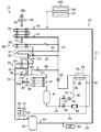
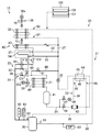
- FIG. 1 is a piping system diagram showing a refrigerant circuit of a container refrigeration apparatus according to this embodiment.
- FIG. 2 is a block diagram illustrating a determination operation according to the present embodiment.
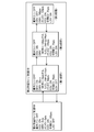
- FIG. 3 is a block diagram showing refrigerant charge control during the heating operation according to the present embodiment.
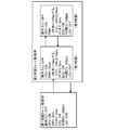
- FIG. 4 is a block diagram showing the refrigerant charge control in the defrost operation according to the present embodiment.
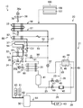
- FIG. 5 is a piping diagram showing the cooling operation of the cooling operation according to the present embodiment.
- FIG. 6 is a piping system diagram showing the cooling operation of the cooling operation according to the present embodiment.
- FIG. 7 is a piping diagram showing a heating operation and a defrost operation in the cooling operation according to the present embodiment.
- FIG. 1 is a piping system diagram showing a refrigerant circuit of a container refrigeration apparatus according to this embodiment.
- FIG. 2 is a block diagram illustrating a determination operation according to the present embodiment.
- FIG. 3 is
- FIG. 8 is a piping diagram illustrating the first refrigerant charge control according to the present embodiment.
- FIG. 9 is a piping diagram illustrating a first stage of second refrigerant charge control during the heating operation according to the present embodiment.
- FIG. 10 is a piping diagram illustrating a second stage of the second refrigerant charge control during the heating operation according to the present embodiment.
- FIG. 11 is a piping diagram illustrating a third stage of the second refrigerant charge control during the heating operation according to the present embodiment.
- the container refrigeration apparatus (10) of the present embodiment cools the interior of a container (not shown).
- the container refrigeration apparatus (10) also serves as a lid that closes the side opening surface of the container body.
- the container refrigeration apparatus (10) includes a refrigerant circuit (20) that circulates refrigerant and performs a cooling cycle.
- the refrigerant circuit (20) includes a main circuit (21), a hot gas bypass circuit (22), a reheat circuit (80), and a supercooling circuit (23).
- the main circuit (21) includes a compressor (30), a condenser (31), a main expansion valve (32), and an evaporator (33) connected in series by a refrigerant pipe in order.
- the compressor (30) has a motor (not shown) that drives the compression mechanism.
- the rotation speed of the motor of the compressor (30) is controlled in multiple stages by an inverter. That is, the compressor (30) is configured such that the operating rotational speed N is variable.
- the condenser (31) and the evaporator (33) are both fin-and-tube heat exchangers.
- the condenser (31) is arranged outside the warehouse. In the condenser (31), heat is exchanged between the outside air and the refrigerant.
- the evaporator (33) is arrange
- a drain pan (37) is provided below the evaporator (33).
- the drain pan (37) is formed in a flat container shape whose upper side is open. Inside the drain pan (37), frost and ice blocks that have fallen off from the evaporator (33), condensed water condensed from the air, and the like are collected.
- the main expansion valve (32) is configured such that the opening degree can be adjusted in multiple stages by a pulse motor.
- the main expansion valve (32) constitutes the main EV in FIGS.
- the condenser (31) is provided with an external fan (35), while the evaporator (33) is provided with an internal fan (36).
- the internal fan (36) is configured to supply the cooling air cooled by the evaporator (33) into the internal space.
- the external fan (35) and the internal fan (36) are provided with an external fan motor (35a) and an internal fan motor (36a), respectively.
- a fourth open / close valve (38) and a check valve (CV) are sequentially provided in the high-pressure gas pipe (24) between the compressor (30) and the condenser (31).
- the fourth on-off valve (38) is configured such that the opening degree can be adjusted in multiple stages by a pulse motor.
- the fourth on-off valve (38) constitutes the DMV in FIGS.
- the check valve (CV) allows the refrigerant to flow in the direction of the arrow shown in FIG. 1 and prohibits the reverse flow.
- the high pressure liquid pipe (25) between the condenser (31) and the main expansion valve (32) includes a receiver (41), a second on-off valve (49), a dryer (43), and a supercooling heat exchanger ( 44) and so on.
- the receiver (41) is provided on the downstream side of the condenser (31), and is configured to allow the refrigerant that has flowed through the condenser (31) to flow into the saturated liquid and the saturated gas.
- the second on-off valve (49) is an openable / closable solenoid valve.
- the second on-off valve (49) constitutes the LSV in FIGS.
- the dryer (43) is configured to capture moisture in the liquid refrigerant that has flowed through the condenser (31).
- a liquid seal prevention pipe (90) connected to the downstream side of the main expansion valve (32) is connected to the upstream side of the condenser (31).
- the liquid seal prevention pipe (90) is provided with a liquid seal on-off valve (91).
- the supercooling heat exchanger (44) cools the liquid refrigerant that has flowed through the condenser (31).
- the supercooling heat exchanger (44) has a primary side passage (45) and a secondary side passage (46). That is, in the supercooling heat exchanger (44), the refrigerant flowing through the primary side passage (45) and the refrigerant flowing through the secondary side passage exchange heat.
- the primary side passage (45) is connected to the high-pressure liquid pipe (25) of the main circuit (21), and the secondary side passage (46) is connected to the supercooling branch pipe (26) of the supercooling circuit (23). Has been.
- the inflow end of the supercooling branch pipe (26) is connected between the receiver (41) and the second on-off valve (49) in the high-pressure liquid pipe (25).
- the outflow end of the supercooling branch pipe (26) is connected to a compression chamber (intermediate compression chamber) in the middle of compression (intermediate pressure state) of the compressor (30). That is, the subcooling branch pipe (26) is a passage through which a part of the liquid refrigerant in the high-pressure liquid pipe (25) is divided and flows into the intermediate compression chamber of the compressor (30).
- a first on-off valve (47) and a supercooling expansion valve (48) are provided on the inflow side of the secondary passage (46) in the supercooling branch pipe (26).
- the first on-off valve (47) is an openable / closable solenoid valve.
- the first on-off valve (47) constitutes the ESV in FIGS.
- the supercooling expansion valve (48) can be adjusted in multiple stages by a pulse motor, and constitutes a decompression mechanism for decompressing the refrigerant.
- the supercooling expansion valve (48) constitutes the intermediate EV in FIGS.
- the hot gas bypass circuit (22) has one main passage (50) and two branch passages (51, 52) branched from the main passage (50).
- the two branch passages (51, 52) refer to a first branch passage (51) and a second branch passage (52).
- the inflow end of the main passage (50) is connected between the fourth on-off valve (38) in the high-pressure gas pipe (24) and the discharge side of the compressor (30).
- a third on-off valve (53) is provided in the main passage (50).
- the third on-off valve (53) is an openable / closable solenoid valve.
- the third on-off valve (53) constitutes the HSV in FIGS.
- the first branch passage (51) has one end connected to the outflow end of the main passage (50) and the other end connected to the low-pressure liquid pipe (27) between the main expansion valve (32) and the evaporator (33). It is connected.
- the second branch passage (52) has one end connected to the outflow end of the main passage (50) and the other end connected to the low-pressure liquid pipe (27).
- the second branch passage (52) is composed of a refrigerant pipe that is longer than the first branch passage (51).
- the second branch passage (52) has a drain pan heater (54) arranged meandering along the bottom of the drain pan (37).
- the drain pan heater (54) is configured to heat the inside of the drain pan (37) with a refrigerant.
- the hot gas bypass circuit (22) supplies the refrigerant compressed by the compressor (30) (the high-temperature gas refrigerant discharged from the compressor (30)) to the evaporator (33).
- a bypass circuit is configured.
- the reheat circuit (80) has a reheat passage (82).
- the inflow end of the reheat passage (82) is connected between the fourth on-off valve (38) in the high-pressure gas pipe (24) and the discharge side of the compressor (30).
- the reheat passage (82) is provided with a fifth on-off valve (81).
- the fifth on-off valve (81) is an openable / closable solenoid valve.
- the reheat passage (82) has a reheat heat exchanger (83) and a capillary tube. In the dehumidifying operation, the reheat heat exchanger (83) exchanges heat between the discharged refrigerant that has flowed in and the air that has been cooled and dehumidified by the evaporator (33), and heats the air. .
- the reheat heat exchanger (83) is a fin-and-tube heat exchanger.
- the capillary tube decompresses the refrigerant that has flowed out of the reheat heat exchanger (83).
- the reheat circuit (80) supplies a part of the refrigerant (high-temperature gas refrigerant discharged from the compressor (30)) compressed by the compressor (30) to the reheat heat exchanger (83).
- the circuit for doing is comprised. Note that the description of the dehumidifying operation is omitted.
- the refrigerant circuit (20) is also provided with various sensors.
- the high pressure gas pipe (24) is provided with a high pressure sensor (60), a high pressure switch (61), and a discharge temperature sensor (62).
- the high pressure sensor (60) detects the pressure of the high pressure gas refrigerant discharged from the compressor (30).
- the discharge temperature sensor (62) detects the temperature of the high-pressure gas refrigerant discharged from the compressor (30).
- the low pressure gas pipe (28) between the evaporator (33) and the compressor (30) is provided with a low pressure sensor (63) and a suction temperature sensor (64).
- the low pressure sensor (63) detects the pressure of the low pressure gas refrigerant sucked into the compressor (30).
- the suction temperature sensor (64) detects the temperature of the low-pressure gas refrigerant sucked into the compressor (30).
- the subcooling branch pipe (26) is provided with an inflow temperature sensor (65) on the inflow side of the secondary side passage (46) and an outflow temperature sensor (66) on the outflow side of the secondary side passage (46). It has been.
- the inflow temperature sensor (65) detects the temperature of the refrigerant immediately before flowing into the secondary side passage (46).
- the outflow temperature sensor (66) detects the temperature of the refrigerant immediately after flowing out of the secondary side passage (46).
- the low-pressure liquid pipe (27) is provided with an inflow temperature sensor (67) on the inflow side of the evaporator (33).
- the inflow temperature sensor (67) detects the temperature of the refrigerant immediately before flowing into the evaporator (33).
- the low pressure gas pipe (28) is provided with an outflow temperature sensor (68) on the outflow side of the evaporator (33).
- the outflow temperature sensor (68) detects the temperature of the refrigerant immediately after flowing out of the evaporator (33).
- an outside air temperature sensor (69) is provided on the suction side of the condenser (31).
- the outside air temperature sensor (69) detects the temperature of the outside air just before being sucked into the condenser (31) (that is, the temperature of the outside air).
- a suction temperature sensor (70) is provided on the suction side of the evaporator (33), and an outlet temperature sensor (71) is provided on the outlet side of the evaporator (33).
- the suction temperature sensor (70) detects the temperature of the internal air immediately before passing through the evaporator (33).
- the blowing temperature sensor (71) detects the temperature of the internal air immediately after passing through the evaporator (33) (the blowing air temperature SS).
- the container refrigeration apparatus (10) is provided with a controller (100) as a control unit for controlling the refrigerant circuit (20).
- the controller (100) includes a refrigerant amount determination unit (106) that determines whether or not the refrigerant amount of the refrigerant circuit (20) is insufficient in the heating operation or the defrost operation of the cooling operation, and the refrigerant amount determination unit (106 ) And a refrigerant amount adjusting unit (107) for replenishing (charging) the refrigerant in the circulation flow of the refrigerant circuit (20).
- the heating operation and the defrost operation in the cooling operation constitute a bypass operation according to the present invention.
- the refrigerant amount determination unit (106) performs determination 1 and determination 2, as shown in FIG.
- determination 1 it is determined that the temperature of the refrigerant discharged from the compressor (30) is abnormally high, and refrigerant charge control is performed.
- the condition of the determination 2 it is determined that the temperature of the refrigerant discharged from the compressor (30) is an appropriate temperature, and the operation returns to the cooling operation or the defrost operation.
- the determination 1 when the state corresponding to the pressure equivalent saturation temperature HP (T) of the high-pressure refrigerant is too low and the superheat degree SH (DCHS-HP (T)) of the discharged refrigerant is 35 ° C. or more continues for 1 minute, and defrost During operation or heating operation, when the operation speed N of the compressor (30) reaches an upper limit value, it is determined that the temperature of the refrigerant discharged from the compressor (30) is abnormally high.
- the 35 ° C. constitutes a predetermined value related to the superheat degree SH of the compressed refrigerant according to the present invention, and the one minute constitutes a predetermined time related to the superheat degree SH of the compressed refrigerant according to the present invention.
- the superheat degree SH of the discharged refrigerant can be reduced by increasing the operating speed N and increasing the refrigerant circulation amount.
- the superheat degree SH can be changed and stabilized more quickly than the refrigerant charge control. Therefore, when the operation speed N of the compressor (30) cannot be increased any more than the upper limit value, the superheat degree SH of the discharged refrigerant is reduced by performing the first refrigerant charge control.
- the determination 1 if the state corresponding to the pressure equivalent saturation temperature LP (T) of the low-pressure refrigerant is too low and the superheat degree SH (SGS-LP (T)) of the suction refrigerant is 25 ° C. or more continues for 3 minutes,
- the operation speed N of the compressor (30) reaches the upper limit value, it is determined that the temperature of the refrigerant discharged from the compressor (30) is abnormally high.
- the 25 ° C. constitutes a predetermined value related to the superheat degree SH of the suction refrigerant according to the present invention.
- the operation returns to the cooling operation or the defrost operation. That is, when the pressure (high pressure) HPT of the discharge refrigerant of the compressor (30) is 1500 kPa or more or the superheat degree SH (DCHS-HP (T)) of the discharge refrigerant is 10 ° C. or less, the compressor Returning to normal heating operation or defrost operation assuming that the discharge temperature of (30) becomes appropriate. In addition, when 5 minutes have passed since the refrigerant charge control was started, the normal heating operation or defrost operation is resumed.
- the value which shows the specific temperature condition, time condition, or pressure condition in the said determination 1 or 2 is an illustration, and is not limited to this.
- the refrigerant amount adjusting unit (107) adjusts the shortage of the refrigerant flow rate circulating in the refrigerant circuit (20). As shown in FIGS. 3 and 4, the refrigerant amount adjusting unit (107) performs first refrigerant charge control and second refrigerant charge control. 3 shows the refrigerant charge control during the heating operation, FIG. 4 shows the refrigerant charge control during the defrost operation, and the first refrigerant charge control of FIG. 3 and the first refrigerant charge control of FIG. It is.
- the third on-off valve (53), the first on-off valve (47), and the supercooling expansion valve (48) are opened during the heating operation or the defrost operation, and the fourth on-off valve (38).
- the liquid refrigerant in the receiver (41) passes through the supercooling branch pipe (26) and is a compression chamber in an intermediate pressure state in the compressor (30). To flow into.
- the second refrigerant charge control during the heating operation (FIG. 3) is performed in the first to third stages, and the second refrigerant charge control during the defrost operation (FIG. 4) is performed in the first to second stages. Is done.
- the compressor (30) is opened with the fourth on-off valve (38) slightly opened and the second on-off valve (49) closed.
- the discharged refrigerant (compressed refrigerant according to the present invention) is caused to flow into the high-pressure liquid pipe (25).
- pressure liquid pipe (25) increases, and a pressure becomes high.
- the second on-off valve (49) and the main expansion valve (32) that were closed in the first stage are fully opened, and the condenser (31)
- the high-pressure refrigerant accumulated in the receiver (41) and the high-pressure liquid pipe (25) flows through the second on-off valve (49) and the main expansion valve (32) to the evaporator (33).
- the 3rd on-off valve (53) opened in the 2nd step will be in a fully closed state, and the discharge refrigerant of compressor (30) will be a condenser ( 31), flows into the receiver (41) and the high-pressure liquid pipe (25).
- the second on-off valve (49) and the main expansion valve (32) are opened, the refrigerant accumulated in the condenser (31), the receiver (41), and the high-pressure liquid pipe (25) It flows through the second on-off valve (49) and the main expansion valve (32) to the evaporator (33).
- the fourth on-off valve (38) is slightly opened and the second on-off valve (49) and the main expansion valve (32) are closed.
- the supercooling expansion valve (48) is opened, and the refrigerant discharged from the compressor (30) (the compressed refrigerant according to the present invention) is caused to flow into the high-pressure liquid pipe (25).
- pressure liquid pipe (25) increases, and a pressure becomes high.
- the fourth on-off valve (38) is further opened from the state of the first stage.
- the refrigerant accumulated in the condenser (31), the receiver (41), and the high-pressure liquid pipe (25) passes through the supercooling branch pipe (26) to the compression chamber in the intermediate pressure state in the compressor (30). Inflow.
- the first stage during the heating operation and the defrost operation described above constitutes the refrigerant inflow operation according to the present invention
- the second to third stages during the heating operation constitute the first refrigerant replenishment operation according to the present invention
- the second stage during the defrost operation constitutes the second refrigerant supply operation according to the present invention.
- the operation of the container refrigeration apparatus (10) is roughly classified into “cooling operation” and “defrost operation”.
- the cooling operation is an operation for cooling the interior of the container to a relatively low temperature. That is, the cooling operation is an operation of refrigeration / cooling the inside of the warehouse in order to preserve the transported goods (for example, fresh food) accommodated in the container body.
- the refrigerant discharged from the compressor (30) is passed through the hot gas bypass circuit (22) to melt the frost adhering to the surface of the heat transfer tube of the evaporator (33) (defrosting). Driving).
- the defrost operation is executed, for example, every time a predetermined set time elapses from the start of the cooling operation, and the cooling operation is resumed after the defrost operation ends.
- the refrigerant compressed by the compressor (30) is condensed by the condenser (31) and then passes through the receiver (41).
- a part of the refrigerant that has passed through the receiver (41) flows through the low-pressure liquid pipe (27) as it is, and the rest is divided into the supercooling branch pipe (26).
- the refrigerant that has flowed through the low-pressure liquid pipe (27) is depressurized by the main expansion valve (32), and then flows through the evaporator (33).
- the evaporator (33) the refrigerant absorbs heat from the internal air and evaporates. Thereby, the air in a warehouse is cooled.
- the refrigerant evaporated in the evaporator (33) is sucked into the compressor (30) and compressed again.
- the refrigerant divided into the supercooling branch pipe (26) passes through the supercooling expansion valve (48) and is reduced to an intermediate pressure, and then passes through the secondary passage (46) of the supercooling heat exchanger (44). Flowing. In the supercooling heat exchanger (44), heat is exchanged between the refrigerant flowing through the primary passage (45) and the refrigerant flowing through the secondary passage (46). As a result, the refrigerant in the primary passage (45) is subcooled, while the refrigerant in the secondary passage (46) evaporates. The refrigerant that has flowed out of the secondary passage (46) is sucked into the compression chamber in the intermediate pressure state from the intermediate port of the compressor (30).
- the line from the fully closed main expansion valve (32) to the suction port of the compressor (30) ie, the low pressure liquid pipe (27) and the low pressure gas pipe (28)
- the refrigerant is sucked into the compressor (30).
- the refrigerant discharged from the compressor (30) is condensed in the condenser (31) to be in a liquid state and stored in the receiver (41). Thereby, in the pump-down operation, the refrigerant in the refrigerant circuit (20) is collected in the receiver (41).
- the operating speed N (operating frequency) of the compressor (30) is controlled to be constant in principle. Moreover, the rotation speed of the outside fan (35) becomes the maximum rotation speed. Thereby, the condensation of the refrigerant is promoted in the condenser.
- This heating operation is executed when the temperature inside the container is lower than the target temperature and the inside of the container is excessively cooled.
- a pump-down operation is performed immediately before the heating operation.
- the second on-off valve (49) is closed and the third on-off valve (53) is opened.
- the main expansion valve (32) is fully closed (0 pulse).
- the first on-off valve (47), the fourth on-off valve (38), the fifth on-off valve (81) and the supercooling expansion valve (48) are in a fully closed state (0 pulse) in principle. Then, while the compressor (30) and the internal fan (36) are operated, the external fan (35) is basically stopped.
- the refrigerant compressed by the compressor (30) is supplied to the evaporator (33) via the hot gas bypass circuit (22). Specifically, the high-temperature and high-pressure gas refrigerant flows through the main circuit (21) and then splits into the first branch passage (51) and the second branch passage (52). The refrigerant branched to the second branch passage (52) passes through the drain pan heater (54) and then merges with the refrigerant flowing out of the first branch passage (51). The combined refrigerant flows to the evaporator (33). In the evaporator (33), the refrigerant dissipates heat to the internal air. As a result, the internal air is heated, so that the internal temperature can be brought close to the target temperature. The refrigerant radiated by the evaporator (33) is sucked into the compressor (30) and compressed.
- the high-temperature and high-pressure gas refrigerant compressed by the compressor (30) is converted into a condenser (31), a receiver (41), a supercooling heat exchanger (44), and a main expansion valve.
- This is an operation of bypassing (32) and supplying directly to the evaporator (33).
- the third on-off valve (53) is opened, the second on-off valve (49) is fully closed (0 pulse), the first on-off valve (47), the fourth on-off valve (38), the fifth The on-off valve (81) and the supercooling expansion valve (48) are in a fully closed state (0 pulse) in principle.
- the compressor (30) starts operation, and the outside fan (35) and the inside fan (36) are stopped in principle.
- the refrigerant compressed by the compressor (30) is supplied to the evaporator (33) via the hot gas bypass circuit (22). Specifically, after the high-pressure gas refrigerant flows through the main circuit (21), it passes through the third on-off valve (53) and is divided into the first branch passage (51) and the second branch passage (52). The refrigerant branched to the second branch passage (52) passes through the drain pan heater (54). Here, in the drain pan (37), ice blocks and the like peeled off from the surface of the evaporator (33) are collected. The ice blocks and the like are heated and melted by the refrigerant flowing inside the drain pan heater (54). The melted water is discharged out of the warehouse through a predetermined channel.
- the refrigerant that has flowed out of the drain pan heater (54) merges with the refrigerant that has passed through the first branch passage (51), and flows through the evaporator (33).
- a high-pressure gas refrigerant (so-called hot gas) flows through the heat transfer tube.
- hot gas a high-pressure gas refrigerant
- surroundings of a heat exchanger tube is gradually heated from the inside with a refrigerant
- the frost adhering to the evaporator (33) is gradually collected in the drain pan (37).
- the refrigerant used for defrosting of the evaporator (33) is sucked into the compressor (30) and compressed.
- the high pressure discharge pressure of the compressor (30)
- the high pressure constant control is performed.
- the operating speed of the compressor (30) during the defrost operation is higher than the operating speed of the compressor (30) during the heating operation.
- the refrigerant amount adjusting unit (107) determines whether to perform the first refrigerant charge control or the second refrigerant charge control based on the outside air temperature (the detected value of the outside air temperature sensor (69)). Specifically, as shown in FIG. 5, in the heating operation, the first refrigerant charge control is performed when the outside air temperature is ⁇ 5 ° C. or higher (broken line A), and the second refrigerant when the outside air temperature is less than ⁇ 5 ° C. Charge control is performed (broken line B). In the case of the defrost operation, as shown in FIG. 5, the first refrigerant charge control is performed when the outside air temperature is 10 ° C. or higher (solid line C), and the second refrigerant charge control is performed when the outside air temperature is less than 10 ° C. ( Solid line D).
- the first on-off valve (47) and the supercooling expansion valve (48) are opened by the refrigerant amount adjusting unit (107).
- the fourth on-off valve (38) is in the closed state (0 pulse), and the outside fan (35) remains stopped.
- the third on-off valve (53) is in an open state, and the second on-off valve (49) and the main expansion valve (32) are in a closed state.
- the liquid refrigerant accumulated in the receiver (41) flows into the compression chamber in the intermediate pressure state in the compressor (30) through the supercooling branch pipe (26). As a result, as shown in FIG.
- HP (T) is a pressure equivalent saturation temperature of the discharge refrigerant (high pressure refrigerant) of the compressor (30)
- DCHS is a temperature detected by the discharge temperature sensor (62).
- LP (T) is the saturation temperature corresponding to the pressure of the suction refrigerant (low pressure refrigerant) of the compressor (30)
- SGS is the temperature detected by the suction temperature sensor (64).
- HPT is the pressure of the refrigerant (high-pressure refrigerant) discharged from the compressor (30).
- the first refrigerant charge control is performed when the outside air temperature is relatively high as described above.
- the refrigerant pressure in the high-pressure liquid pipe (25) is relatively high, and compression of the intermediate pressure state in the high-pressure liquid pipe (25) and the compressor (30) that is the charge (replenishment) destination A sufficient pressure difference from the chamber can be secured. Therefore, the refrigerant in the high-pressure liquid pipe (25) can be easily flowed to the compressor (30) by the pressure difference only by opening the first on-off valve (47) and the supercooling expansion valve (48).
- the refrigerant amount determination unit (106) determines that the refrigerant flow rate is appropriate by satisfying the condition of determination 2 after the first refrigerant charge control, the normal heating operation or defrost operation shown in FIG. 7 is resumed. That is, when the pressure (high pressure) HPT of the discharge refrigerant of the compressor (30) is 1500 kPa or more, or the superheat degree SH (DCHS-HP (T)) of the discharge refrigerant is 10 ° C. or less, the compressor ( Assuming that the temperature of the refrigerant discharged in 30) is appropriate, the normal heating operation or defrosting operation is resumed. Also, when 5 minutes have passed since entering the refrigerant charge control, the normal heating operation or defrosting operation is resumed.
- the second refrigerant charge control is performed as shown in FIGS. Is done.
- the refrigerant valve controller (107) opens the fourth on-off valve (38) to an opening of 30 pulses, and the main expansion valve (32) to 55 pulses. Opened and the second on-off valve (49) is closed. Then, the supercooling expansion valve (48) is throttled to 70 pulses. At this time, the first on-off valve (47) and the third on-off valve (53) are in an open state, and the outside fan (35) remains stopped.
- the fourth on-off valve (38) is opened up to 150 pulses at the maximum every 30 pulses every 5 seconds. By doing so, as shown in FIG.
- the high-temperature and high-pressure gas refrigerant discharged from the compressor (30) passes from the fourth on-off valve (38) to the condenser (31), the receiver (41), and the high-pressure liquid pipe ( Compressed refrigerant flows into 25) and the pressure of the accumulated refrigerant increases.
- the second refrigerant charge control proceeds to the second stage.
- the refrigerant amount adjusting unit (107) opens the fourth on-off valve (38) by 100 pulses every 5 seconds, up to 350 pulses. Further, the main expansion valve (32) is opened up to 100 pulses, and the second on-off valve (49) is opened.
- the refrigerant accumulated in the condenser (31), the receiver (41), and the high-pressure liquid pipe (25) becomes the second on-off valve (49) and the main expansion valve (32).
- the second refrigerant charge control proceeds to the third stage.
- the refrigerant amount adjusting unit (107) opens the fourth on-off valve (38) up to 760 pulses, and the third on-off valve (53) is fully closed. . That is, the refrigerant circuit (20) is in the same state as the cooling operation of the cooling operation. In this third stage, as shown in FIG.
- the high-temperature and high-pressure gas refrigerant discharged from the compressor (30), together with the refrigerant accumulated in the condenser (31), receiver (41), and high-pressure liquid pipe (25), is discharged from the main expansion valve (32) to the evaporator. Since it is supplied to (33), the flow rate of the refrigerant flowing through the evaporator (33) increases. For this reason, the refrigerating machine oil remaining in the evaporator (33) can be reliably recovered.
- the refrigerant amount adjusting unit (107) opens the fourth on-off valve (38) to an opening of 30 pulses, and the main expansion valve (32) and the second on-off valve are opened and closed.
- the valve (49) is closed.
- the supercooling expansion valve (48) opens up to 200 pulses.
- the first on-off valve (47) and the third on-off valve (53) are in an open state, and the outside fan (35) remains stopped.
- the fourth on-off valve (38) is opened up to 150 pulses at the maximum every 30 pulses every 5 seconds.
- the high-temperature and high-pressure gas refrigerant discharged from the compressor (30) is discharged from the fourth on-off valve (38) to the condenser (31 ),
- the compressed refrigerant flows into the receiver (41) and the high-pressure liquid pipe (25), and the pressure of the accumulated refrigerant increases.
- the second refrigerant charge control proceeds to the second stage.
- the second stage of the second refrigerant charge control during the defrost operation is the same state as the first stage except for the fourth on-off valve (38).
- the fourth on-off valve (38) is opened up to 350 pulses at the maximum by 100 pulses every 5 seconds by the refrigerant amount adjusting unit (107).
- the refrigerant accumulated in the condenser (31), the receiver (41), and the high-pressure liquid pipe (25) flows into the first on-off valve (47) and the supercooling expansion valve (48). ), That is, through the supercooling branch pipe (26), flows into the compression chamber in the intermediate pressure state in the compressor (30).
- the refrigerant in the high-pressure liquid pipe (25) is charged (supplemented) into the refrigerant circulation in the defrost operation, and the refrigerant flow rate during the defrost operation increases.
- the superheat degree SH of the refrigerant discharged from the compressor (30) is lowered, and the refrigeration oil remaining in the evaporator (33) is reliably recovered. Is done.
- the second refrigerant charge control is performed when the outside air temperature is relatively low as described above (that is, when the outside air is low). At low outside air, the refrigerant pressure in the high-pressure liquid pipe (25) is low, and in this state, the high-pressure liquid pipe (25) and the evaporator (33) and compressor (30) that are the charge (replenishment) destination A sufficient pressure difference from the compression chamber in the intermediate pressure state cannot be secured. If it does so, a sufficient quantity of refrigerant
- the refrigerant pressure in the high-pressure liquid pipe (25) is increased (the first stage is performed) before charging the refrigerant. Even at that time, the pressure difference can be secured, and a sufficient amount of refrigerant can be charged.
- the refrigerant inflow operation (the first stage of the second refrigerant charge control) for causing the compressed refrigerant to flow into the high-pressure liquid pipe (25) in the heating operation and the defrost operation at the time of low outside air with a low outside air temperature. Since the refrigerant pressure in the high-pressure liquid pipe (25) is increased, intermediate pressure compression is performed in the high-pressure liquid pipe (25) and the evaporator (33) or compressor (30) that is the charge (replenishment) destination. A sufficient pressure difference from the chamber can be secured.
- the refrigerant in the high pressure liquid pipe (25) can be reliably charged (supplemented) into the refrigerant circulation in the heating operation and defrost operation. .
- the refrigerant in the high-pressure liquid pipe (25) is caused to flow from the main expansion valve (32) to the evaporator (33), the high-pressure refrigerant can be allowed to flow into the evaporator (33). Thereby, the refrigeration oil remaining in the evaporator (33) can be reliably recovered.
- the operating speed of the compressor (30) is higher and the high pressure (discharge pressure of the compressor (30)) is higher than in the heating operation in order to increase the defrosting capacity. Therefore, the refrigerant pressure in the high pressure liquid pipe (25) is higher in the refrigerant inflow operation in the defrost operation than in the refrigerant inflow operation in the heating operation. Therefore, in the defrost operation, if the refrigerant replenishment operation is performed in which the refrigerant in the high-pressure liquid pipe (25) flows into the evaporator (33) through the main expansion valve (32) as in the heating operation, the refrigerant is excessively replenished. End up.
- the refrigerant in the high pressure liquid pipe (25) is passed through the supercooling branch pipe (26) in the compressor (30). It flows into the compression chamber in the intermediate pressure state. Since the inflow portion of the refrigerant into the compression chamber is provided with a resistance so that a large amount of refrigerant does not flow, it is possible to prevent the refrigerant from being replenished excessively. As a result, oil leakage in the compressor (30) can be prevented, leading to improved reliability. That is, in the defrost operation, the refrigerant replenishment amount can be made appropriate by performing the refrigerant replenishment operation of flowing the refrigerant in the high pressure liquid pipe (25) into the compression chamber in the intermediate pressure state in the compressor (30).
- the refrigerant inflow operation can be performed when the refrigerant is surely short in the heating operation and the defrost operation.
- the refrigerant inflow operation is performed when the operating speed N of the compressor (30) reaches the upper limit during the defrost operation, the refrigerant inflow occurs when the refrigerant is surely in a shortage state during the defrost operation.
- the action can be performed.
- the refrigerant inflow operation is performed when the operation rotational speed N of the compressor (30) reaches the upper limit, and therefore the refrigerant is surely in a shortage state during the heating operation.
- the refrigerant inflow operation can be performed.
- the superheat degree SH of the refrigerant sucked in the compressor (30) becomes 25 ° C. or higher, a part of the high-temperature high-pressure gas refrigerant discharged from the compressor (30) is a high-pressure liquid containing the condenser (31). Since it is made to flow into the pipe (25), the pressure of the refrigerant in the high-pressure liquid pipe (25) can be increased. For this reason, the compressed refrigerant of the compressor (30) is supplied to the circulating flow returning to the compressor (30) through the hot gas bypass circuit (22) and the evaporator (33) without leaving the refrigerant of the high-pressure liquid pipe (25). be able to. Thereby, since the refrigerant
- the present invention may be configured as follows for the above embodiment.
- the same control as the second refrigerant charge control (FIG. 3) during the heating operation may be added as the third refrigerant charge control. That is, in the defrost operation, the refrigerant amount adjustment unit (107) determines which of the first refrigerant charge control to the third refrigerant charge control is performed based on the outside air temperature. Specifically, as described above, the second refrigerant charge control may be performed when the outside air temperature is less than 10 ° C., and the third refrigerant charge control may be performed when the outside air temperature is less than ⁇ 30 ° C.
- the second refrigerant charge control (FIG. 4) may be changed to the same control as the second refrigerant charge control (FIG. 3) during the heating operation.
- the present invention is useful for a container refrigeration apparatus.
- Refrigerant circuit 20 Refrigerant circuit 22 Hot gas bypass circuit 30 Compressor 31 Condenser 32 Expansion valve 33 Evaporator 107 Refrigerant amount adjustment unit
Landscapes
- Engineering & Computer Science (AREA)
- Physics & Mathematics (AREA)
- Mechanical Engineering (AREA)
- Thermal Sciences (AREA)
- General Engineering & Computer Science (AREA)
- Devices That Are Associated With Refrigeration Equipment (AREA)
- Defrosting Systems (AREA)
Abstract
コンテナ用冷凍装置(10)は、ホットガスバイパス回路(22)を有して冷凍サイクルを行う冷媒回路(20)を備え、圧縮機(30)の圧縮冷媒をホットガスバイパス回路(22)を通過させて蒸発器(33)へ流入させるバイパス運転が行われるものを対象としている。バイパス運転時において、圧縮機(30)の圧縮冷媒の一部を凝縮器(31)を含む高圧液管(25)に流入させる冷媒流入動作と、該冷媒流入動作の後に高圧液管(25)の冷媒を蒸発器(33)に流入させる冷媒補給動作とを実行可能な冷媒量調節部(107)を備えている。
Description
本発明は、コンテナ用冷凍装置に関し、特に、デフロスト運転又は冷却運転中の加熱動作における冷媒流量の増加対策に係るものである。
従来、冷凍サイクルを行う冷凍装置として、コンテナの庫内を冷却するコンテナ用冷凍装置がある。特許文献1には、この種のコンテナ用冷凍装置が開示されている。
上記コンテナ用冷凍装置は、圧縮機と凝縮器と膨張弁と蒸発器とが接続される冷媒回路を備えている。蒸発器は、コンテナの庫内に設けられている。蒸発器では、冷媒が庫内の空気から吸熱して蒸発する。これにより庫内空気が冷却される。
また、このコンテナ用冷凍装置の冷媒回路には、圧縮機で圧縮された冷媒(いわゆるホットガス)を凝縮器を介さずに蒸発器へ供給するためのバイパス回路が設けられている。このバイパス回路は、2本のバイパス管と、各々のバイパス管に対応する2つの開閉弁とを有している。各バイパス管は、圧縮機と凝縮器との間のガスラインと、膨張弁と蒸発器との間の液ラインとを連通させている。コンテナ用冷凍装置では、このようなバイパス回路を用いることで、蒸発器を流れるホットガスによって庫内の空気を加熱する加熱動作を行っている。
上述したように、特許文献1に開示のコンテナ用冷凍装置では、2つの開閉弁の開閉状態を切り換えることで、加熱動作時における庫内の加熱能力を調節している。
しかしながら、上述したコンテナ用冷凍装置には、加熱動作において、圧縮機の圧縮冷媒の過熱度SHが高くなった場合に、該過熱度SHを下げる手段がない。このため、特に外気温度が低い低外気時には圧縮機の吐出温度が異常に上昇してしまうという問題があった。
本発明は、斯かる点に鑑みてなされたものであり、冷却運転中の加熱動作時やデフロスト運転時において、冷媒回路の冷媒循環量を増大させることを目的とする。
第1の発明は、圧縮機(30)と凝縮器(31)と膨張弁(32)と蒸発器(33)とが順に接続されると共に、上記圧縮機(30)の圧縮冷媒を上記凝縮器(31)および膨張弁(32)をバイパスして上記蒸発器(33)へ送るためのホットガスバイパス回路(22)を有して冷凍サイクルを行う冷媒回路(20)を備え、上記圧縮機(30)の圧縮冷媒をホットガスバイパス回路(22)を通過させて蒸発器(33)へ流入させるバイパス運転が行われるコンテナ用冷凍装置であって、上記バイパス運転時において、上記圧縮機(30)の圧縮冷媒の一部を上記凝縮器(31)を含む高圧液管(25)に流入させる冷媒流入動作と、該冷媒流入動作の後に上記高圧液管(25)の冷媒を上記膨張弁(32)を通過させて上記蒸発器(33)に流入させる冷媒補給動作とを実行可能な冷媒量調節部(107)を備えている。
上記第1の発明では、冷媒回路(20)において、圧縮機(30)から吐出した冷媒が凝縮器(31)で凝縮された後、膨張弁(32)で膨張し、蒸発器(33)で蒸発する。蒸発器(33)では冷媒とコンテナの庫内空気との間で熱交換され、該庫内空気が冷却される。
次に、バイパス運転では、ホットガスバイパス回路(22)を通過することで、圧縮機(30)から吐出した圧縮冷媒が凝縮器(31)および膨張弁(32)をバイパスして蒸発器(33)へ送られる。そして、バイパス運転時では、例えば低外気時に圧縮冷媒の過熱度SHが高くなると、圧縮機(30)の圧縮冷媒の一部を冷媒回路(20)の凝縮器(31)を含む高圧液管(25)に流入させる冷媒流入動作が行われる。圧縮冷媒が流入されることで、凝縮器(31)を含む高圧液管(25)の冷媒の圧力は高くなる。そして、冷媒量調節部(107)は、凝縮器(31)を含む高圧液管(25)の冷媒を膨張弁(32)を通過させて蒸発器(33)に流入させる冷媒補給動作を行う。
このように、高圧液管(25)に流入させた圧縮冷媒を蒸発器(33)に送るようにしたため、圧縮機(30)の圧縮冷媒がホットガスバイパス回路(22)および蒸発器(33)を経て圧縮機(30)へ戻る循環流れの冷媒量が増大する。これによって、圧縮冷媒の過熱度SHが低下する。また、高圧液管(25)に流入させた圧縮冷媒を蒸発器(33)に送るようにしたため、バイパス運転時において、蒸発器(33)に残留している冷凍機油を回収することができる。
第2の発明は、上記第1の発明において、上記バイパス運転として、上記圧縮機(30)の圧縮冷媒がホットガスバイパス回路(22)および蒸発器(33)を経て圧縮機(30)へ戻る循環流れで上記蒸発器(33)でコンテナ庫内を加熱する加熱動作と、上記圧縮機(30)の圧縮冷媒がホットガスバイパス回路(22)および蒸発器(33)を経て圧縮機(30)へ戻る循環流れで、上記蒸発器(33)の霜を除霜する除霜運転とが実行可能であり、上記冷媒量調節部(107)は、上記加熱動作時において、上記冷媒流入動作と上記冷媒補給動作である第1冷媒補給動作とを実行可能に構成され、上記除霜運転時において、上記冷媒流入動作と、該冷媒流入動作の後に上記高圧液管(25)の冷媒を上記圧縮機(30)の中間圧状態の圧縮室に流入させる第2冷媒補給動作とを実行可能に構成されている。
上記第2の発明では、バイパス運転としての加熱動作時において、圧縮冷媒の過熱度SHが高くなると、上述したように、冷媒流入動作の後、高圧液管(25)の冷媒が蒸発器(33)に補充される。一方、バイパス運転としてのデフロスト運転時において、圧縮冷媒の過熱度SHが高くなると、冷媒流入動作の後、高圧液管(25)の冷媒が圧縮機(30)の中間圧状態の圧縮室に補充される。
第3の発明は、上記第1又は第2の発明において、上記冷媒量調節部(107)は、上記バイパス運転時において、上記圧縮機(30)の圧縮冷媒の過熱度SHが所定値以上となった場合に、上記冷媒流入動作および冷媒補給動作を行うように構成されている。
上記第3の発明では、バイパス運転時において、圧縮機(30)の圧縮冷媒の過熱度SHが所定値以上になると、冷媒流入動作および冷媒補給動作が行われる。
第4の発明は、上記第3の発明において、上記冷媒量調節部(107)は、バイパス運転時において、上記圧縮機(30)の圧縮冷媒の過熱度SHが所定値よりも大きい状態が所定時間、継続した場合に、上記冷媒流入動作および冷媒補給動作を行うように構成されている。
上記第4の発明では、バイパス運転において、圧縮機(30)の圧縮冷媒の過熱度SHが所定値よりも大きい状態が所定時間、継続すると、冷媒量調節部(107)が冷媒流入動作および冷媒補給動作を行う。
第5の発明は、上記第3の発明において、上記冷媒量調節部(107)は、上記バイパス運転時において上記圧縮機(30)の運転回転数Nが上限となった場合に、上記冷媒流入動作および冷媒補給動作を行うように構成されている。
上記第5の発明では、バイパス運転時において、圧縮機(30)の運転回転数Nが上限となった場合に、冷媒量調節部(107)が冷媒流入動作および冷媒補給動作を行う。
第6の発明は、上記第1又は第2の発明において、上記冷媒量調節部(107)は、上記バイパス運転時において、上記圧縮機(30)の吸入冷媒の過熱度SHが所定値以上となった場合に、上記冷媒流入動作および冷媒補給動作を行うように構成されている。
上記第6の発明では、バイパス運転時において、圧縮機(30)の吸入冷媒の過熱度SHが所定値以上になると、冷媒流入動作および冷媒補給動作が行われる。
上記第1の発明によれば、圧縮冷媒の一部を凝縮器(31)を含む高圧液管(25)に流入させるようにしたため、高圧液管(25)内の冷媒の圧力を高くすることができる。このため、圧縮機(30)の圧縮冷媒がホットガスバイパス回路(22)および蒸発器(33)を経て圧縮機(30)へ戻る循環流れに、凝縮器(31)を含む高圧液管(25)の冷媒を残らず供給することができる。これにより、上記循環流れの冷媒が増大するため、圧縮冷媒の過熱度SHを下げることができる。
つまり、高圧液管(25)に圧縮冷媒を流入させる冷媒流入動作を行うことで、高圧液管(25)の冷媒圧力を昇圧して高圧液管(25)と補充先である蒸発器(33)との圧力差を充分に確保することができる。したがって、高圧液管(25)の冷媒圧力が低くなる低外気時であっても、確実に高圧液管(25)の冷媒をバイパス運転の冷媒循環に補充することができる。
また、高圧液管(25)の冷媒を膨張弁(32)から蒸発器(33)に流入させたため、高圧冷媒を大量に蒸発器(33)へ流入させることができる。これにより、蒸発器(33)に残った冷凍機油を確実に回収することができる。
除霜運転では、除霜能力を稼ぐために、加熱動作時よりも圧縮機(30)の運転回転数が高く高圧(圧縮機(30)の吐出圧力)が高い。そのため、除霜運転の冷媒流入動作では、加熱動作の冷媒流入動作よりも高圧液管(25)の冷媒圧力が高くなる。そのため、除霜運転において、加熱動作と同様に高圧液管(25)の冷媒を蒸発器(33)に流入させる冷媒補給動作を行うと、過剰に冷媒が補給されてしまう。そうすると、除霜運転における冷媒の循環量が過剰となり、圧縮機(30)を流れる冷媒が湿り気味となる。圧縮機(30)において、冷媒が湿り気味になると、冷凍機油が冷媒と共に流出しやすくなり、油ぎれが生じてしまう。
そこで、上記第2の発明によれば、加熱動作時の冷媒補給動作(第1冷媒補給動作)では高圧液管(25)の冷媒を蒸発器(33)に補充するようにし、除霜運転時の冷媒補給動作(第2冷媒補給動作)では高圧液管(25)の冷媒を圧縮機(30)における中間圧状態の圧縮室に補充するようにした。この圧縮室への冷媒の流入部は、冷媒が多量に流入しないように抵抗が付けられているため、過剰に冷媒が補充されるのを防止できる。この結果、圧縮機(30)における油ぎれを防止でき、信頼性を向上させることができる。
上記第3の発明によれば、バイパス運転時において圧縮冷媒の過熱度SHが所定値以上になった場合に、さらに上記第4の発明によれば、バイパス運転時において圧縮冷媒の過熱度SHが所定値よりも大きい状態が所定時間、継続した場合に、冷媒流入動作および冷媒補給動作を行うようにしたため、バイパス運転時において確実に冷媒不足状態となったときに、冷媒流入動作等を行うことができる。
さらに、上記第5の発明によれば、バイパス運転時において、圧縮機(30)の運転回転数Nが上限となった場合に冷媒流入動作および冷媒補給動作を行うようにしたため、バイパス運転時において確実に冷媒不足状態となったときに、冷媒流入動作等を行うことができる。
上記第6の発明によれば、バイパス運転時において吸入冷媒の過熱度SHが所定値以上となった場合に冷媒流入動作および冷媒補給動作を行うようにしたため、バイパス運転時において確実に冷媒不足状態となったときに、冷媒流入動作等を行うことができる。
以下、本発明の実施形態を図面に基づいて詳細に説明する。
本実施形態のコンテナ用冷凍装置(10)は、図示しないコンテナの庫内を冷却するものである。コンテナ用冷凍装置(10)は、コンテナ本体の側方の開口面を閉塞する蓋体を兼用している。
図1に示すように、上記コンテナ用冷凍装置(10)は、冷媒が循環して冷却サイクルを行う冷媒回路(20)を備えている。この冷媒回路(20)は、主回路(21)と、ホットガスバイパス回路(22)とレヒート回路(80)と過冷却回路(23)とを有している。
上記主回路(21)は、圧縮機(30)と凝縮器(31)と主膨張弁(32)と蒸発器(33)とが順に冷媒配管によって直列に接続されて構成されている。
上記圧縮機(30)は、圧縮機構を駆動するモータ(図示省略)を有している。この圧縮機(30)のモータの回転数は、インバータによって多段階に制御される。つまり、圧縮機(30)は、運転回転数Nが可変に構成されている。
上記凝縮器(31)および蒸発器(33)は、いずれもフィン・アンド・チューブ熱交換器で構成されている。凝縮器(31)は、庫外に配置されている。凝縮器(31)では、庫外の空気と冷媒とが熱交換する。蒸発器(33)は、庫内に配置されている。蒸発器(33)では、庫内の空気と冷媒とが熱交換する。また、蒸発器(33)の下方には、ドレンパン(37)が設けられている。ドレンパン(37)は、上側が開放された扁平な容器状に形成されている。ドレンパン(37)の内部には、蒸発器(33)から剥がれ落ちた霜や氷塊や、空気中から凝縮した結露水等が回収される。主膨張弁(32)は、開度がパルスモータによって多段階に調節可能に構成されている。主膨張弁(32)は、図2~図4におけるメインEVを構成している。また、上記凝縮器(31)には、庫外ファン(35)が設けられる一方、蒸発器(33)には、庫内ファン(36)が設けられている。該庫内ファン(36)は、蒸発器(33)で冷却された冷却空気を庫内に供給するように構成されている。上記庫外ファン(35)および庫内ファン(36)には、それぞれ庫外ファンモータ(35a)および庫内ファンモータ(36a)が設けられている。
上記圧縮機(30)と凝縮器(31)との間の高圧ガス管(24)には、第4開閉弁(38)と逆止弁(CV)とが順に設けられている。第4開閉弁(38)は、開度がパルスモータによって多段階に調節可能に構成されている。第4開閉弁(38)は、図2~図4におけるDMVを構成している。逆止弁(CV)は、図1に示す矢印の方向への冷媒の流れを許容し、その逆の流れを禁止している。
上記凝縮器(31)と主膨張弁(32)との間の高圧液管(25)には、レシーバ(41)と第2開閉弁(49)とドライヤ(43)と過冷却熱交換器(44)とが順に設けられている。上記レシーバ(41)は、凝縮器(31)の下流側に設けられ、凝縮器(31)を流れた冷媒を流入させ、飽和液と飽和ガスとに分離するように構成されている。上記第2開閉弁(49)は、開閉自在な電磁弁で構成されている。第2開閉弁(49)は、図2~図4におけるLSVを構成している。上記ドライヤ(43)は、凝縮器(31)を流れた液冷媒中の水分を捕捉するように構成されている。凝縮器(31)の上流側には、主膨張弁(32)の下流側に接続される液封防止管(90)が接続されている。この液封防止管(90)には液封開閉弁(91)が設けられている。
上記過冷却熱交換器(44)は、凝縮器(31)を流れた液冷媒を冷却するものである。過冷却熱交換器(44)は、1次側通路(45)と2次側通路(46)を有している。つまり、過冷却熱交換器(44)では、1次側通路(45)を流れる冷媒と2次側通路を流れる冷媒とが熱交換する。1次側通路(45)は、主回路(21)の高圧液管(25)に接続され、2次側通路(46)は、過冷却回路(23)の過冷却分岐管(26)に接続されている。過冷却分岐管(26)の流入端は、高圧液管(25)におけるレシーバ(41)と第2開閉弁(49)の間に接続している。過冷却分岐管(26)の流出端は、圧縮機(30)の圧縮途中(中間圧力状態)の圧縮室(中間圧縮室)と接続している。つまり、過冷却分岐管(26)は、高圧液管(25)の液冷媒の一部が分流し圧縮機(30)の中間圧縮室へ流入する通路である。過冷却分岐管(26)における2次側通路(46)の流入側には、第1開閉弁(47)と過冷却膨張弁(48)とが設けられている。第1開閉弁(47)は、開閉自在な電磁弁で構成されている。第1開閉弁(47)は、図2~図4におけるESVを構成している。過冷却膨張弁(48)は、開度がパルスモータによって多段階に調節可能であり、冷媒を減圧する減圧機構を構成している。過冷却膨張弁(48)は、図2~図4における中間EVを構成している。
上記ホットガスバイパス回路(22)は、1本の主通路(50)と、該主通路(50)から分岐する2本の分岐通路(51,52)とを有している。この2本の分岐通路(51,52)は、第1分岐通路(51)と第2分岐通路(52)をいう。主通路(50)の流入端は、高圧ガス管(24)における第4開閉弁(38)と圧縮機(30)の吐出側との間に接続している。主通路(50)には、第3開閉弁(53)が設けられている。第3開閉弁(53)は、開閉自在な電磁弁で構成されている。第3開閉弁(53)は、図2~図4におけるHSVを構成している。
上記第1分岐通路(51)は、一端が主通路(50)の流出端に接続され、他端が主膨張弁(32)と蒸発器(33)との間の低圧液管(27)に接続されている。同様に、第2分岐通路(52)も、一端が主通路(50)の流出端に接続され、他端が低圧液管(27)に接続されている。第2分岐通路(52)は、第1分岐通路(51)よりも長い冷媒配管で構成されている。また、第2分岐通路(52)は、ドレンパン(37)の底部に沿うように蛇行して配置されたドレンパンヒータ(54)を有している。ドレンパンヒータ(54)は、ドレンパン(37)の内部を冷媒によって加熱するように構成されている。以上にようにして、ホットガスバイパス回路(22)は、圧縮機(30)で圧縮した冷媒(圧縮機(30)から吐出された高温のガス冷媒)を蒸発器(33)へ供給するためのバイパス回路を構成している。
上記レヒート回路(80)は、レヒート通路(82)を有している。レヒート通路(82)の流入端は、高圧ガス管(24)における第4開閉弁(38)と圧縮機(30)の吐出側との間に接続している。レヒート通路(82)には、第5開閉弁(81)が設けられている。この第5開閉弁(81)は、開閉自在な電磁弁で構成されている。上記レヒート通路(82)は、レヒート熱交換器(83)とキャピラリチューブとを有している。レヒート熱交換器(83)は、除湿運転時において、流入させた吐出冷媒と、蒸発器(33)で冷却除湿させた後の空気との間で熱交換させ、該空気を加熱するものである。レヒート熱交換器(83)は、フィン・アンド・チューブ熱交換器で構成されている。キャピラリチューブは、レヒート熱交換器(83)を流出した冷媒を減圧させるものである。以上のようにして、レヒート回路(80)は、圧縮機(30)で圧縮した冷媒(圧縮機(30)から吐出された高温のガス冷媒)の一部をレヒート熱交換器(83)へ供給するための回路を構成している。尚、除湿運転についての説明は省略する。
上記冷媒回路(20)には、各種のセンサ類も設けられている。具体的に、高圧ガス管(24)には、高圧圧力センサ(60)と高圧圧力スイッチ(61)と吐出温度センサ(62)とが設けられている。高圧圧力センサ(60)は、圧縮機(30)から吐出される高圧ガス冷媒の圧力を検出する。吐出温度センサ(62)は、圧縮機(30)から吐出される高圧ガス冷媒の温度を検出する。蒸発器(33)と圧縮機(30)の間の低圧ガス管(28)には、低圧圧力センサ(63)と吸入温度センサ(64)とが設けられている。低圧圧力センサ(63)は、圧縮機(30)に吸入される低圧ガス冷媒の圧力を検出する。吸入温度センサ(64)は、圧縮機(30)に吸入される低圧ガス冷媒の温度を検出する。
上記過冷却分岐管(26)には、2次側通路(46)の流入側に流入温度センサ(65)が、2次側通路(46)の流出側に流出温度センサ(66)がそれぞれ設けられている。流入温度センサ(65)は、2次側通路(46)に流入する直前の冷媒の温度を検出する。また、流出温度センサ(66)は、2次側通路(46)を流出した直後の冷媒の温度を検出する。
上記低圧液管(27)には、蒸発器(33)の流入側に流入温度センサ(67)が設けられている。この流入温度センサ(67)は、蒸発器(33)に流入する直前の冷媒の温度を検出する。低圧ガス管(28)には、蒸発器(33)の流出側に流出温度センサ(68)が設けられている。この流出温度センサ(68)は、蒸発器(33)から流出した直後の冷媒の温度を検出する。
上記コンテナの庫外には、凝縮器(31)の吸込側に外気温度センサ(69)が設けられている。外気温度センサ(69)は、凝縮器(31)に吸い込まれる直前の庫外空気の温度(即ち、外気の温度)を検出する。コンテナの庫内には、蒸発器(33)の吸込側に吸込温度センサ(70)が設けられ、蒸発器(33)の吹出側に吹出温度センサ(71)が設けられている。吸込温度センサ(70)は、蒸発器(33)を通過する直前の庫内空気の温度を検出する。吹出温度センサ(71)は、蒸発器(33)を通過した直後の庫内空気の温度(吹出空気温度SS)を検出する。
図1に示すように、上記コンテナ用冷凍装置(10)には、冷媒回路(20)を制御するための制御部としてのコントローラ(100)が設けられている。そして、コントローラ(100)には、冷却運転の加熱動作やデフロスト運転において、冷媒回路(20)の冷媒量の不足の有無を判定する冷媒量判定部(106)と、該冷媒量判定部(106)の判定結果に基づいて冷媒回路(20)の循環流れに冷媒を補充(チャージ)する冷媒量調節部(107)とが設けられている。尚、上記冷却運転の加熱動作、およびデフロスト運転は、本発明に係るバイパス運転を構成するものである。
上記冷媒量判定部(106)は、図2に示すように、判定1と判定2とが行われる。判定1の条件を満たすと、圧縮機(30)の吐出冷媒の温度が異常高温であると判定され、冷媒チャージ制御が行われる。判定2の条件を満たすと、圧縮機(30)の吐出冷媒の温度が適切な温度であると判定され、冷却運転又はデフロスト運転に戻る。
判定1では、高圧冷媒の圧力相当飽和温度HP(T)が低下しすぎて吐出冷媒の過熱度SH(DCHS-HP(T))が35℃以上となる状態が1分間継続した場合、且つデフロスト運転時又は加熱動作時において、圧縮機(30)の運転回転数Nが上限値となった場合に圧縮機(30)の吐出冷媒の温度が異常高温であると判定される。尚、上記35℃は、本発明に係る圧縮冷媒の過熱度SHに係る所定値を構成し、上記1分間は、本発明に係る圧縮冷媒の過熱度SHに係る所定時間を構成している。
ここで、圧縮機(30)の運転回転数Nに余裕がある場合は、その運転回転数Nを増加させて冷媒循環量を増大させることで、吐出冷媒の過熱度SHを低下することができる。このように圧縮機(30)の運転回転数Nを増加させると、冷媒チャージ制御よりも、過熱度SHを早く変化させて安定させることができる。したがって、圧縮機(30)の運転回転数Nが既に上限値でこれ以上増加させることができない場合に、第1冷媒チャージ制御を行うことにより、吐出冷媒の過熱度SHを低下させる。
また、判定1では、低圧冷媒の圧力相当飽和温度LP(T)が低下しすぎて吸入冷媒の過熱度SH(SGS-LP(T))が25℃以上となる状態が3分間継続した場合、且つ加熱動作時において、圧縮機(30)の運転回転数Nが上限値となった場合、圧縮機(30)の吐出冷媒の温度が異常高温であると判定される。尚、上記25℃は、本発明に係る吸入冷媒の過熱度SHに係る所定値を構成している。
上記判定2では、冷媒量判定部(106)が図2に示す判定2の条件によって冷媒量が適切と判定すると、冷却運転又はデフロスト運転に戻る。即ち、圧縮機(30)の吐出冷媒の圧力(高圧)HPTが1500kPa以上となるか、又は吐出冷媒の過熱度SH(DCHS-HP(T))が10℃以下となった場合に、圧縮機(30)の吐出温度が適切になったとして通常の加熱動作又はデフロスト運転に戻る。また、冷媒チャージ制御に入って5分間経過すれば、通常の加熱動作又はデフロスト運転に戻る。
尚、上記判定1又は2における具体的な温度条件、時間条件又は圧力条件を示す値は例示であり、これに限定されるものではない。
上記冷媒量調節部(107)は、冷媒回路(20)を循環する冷媒流量の不足を調節するものである。冷媒量調節部(107)は、図3および図4に示すように、第1冷媒チャージ制御と、第2冷媒チャージ制御とを行うものである。尚、図3は加熱動作時の冷媒チャージ制御を示し、図4はデフロスト運転時の冷媒チャージ制御を示し、図3の第1冷媒チャージ制御と図4の第1冷媒チャージ制御は同様の制御内容である。
上記第1冷媒チャージ制御では、加熱動作時又はデフロスト運転時において、第3開閉弁(53)、第1開閉弁(47)および過冷却膨張弁(48)を開き、第4開閉弁(38)、第2開閉弁(49)および主膨張弁(32)を閉鎖した状態でレシーバ(41)の液冷媒を過冷却分岐管(26)を通って圧縮機(30)における中間圧状態の圧縮室へ流入させる。
そして、加熱動作時の第2冷媒チャージ制御(図3)は第1~第3段階の動作が行われ、デフロスト運転時の第2冷媒チャージ制御(図4)は第1~第2段階の動作が行われる。
まず、加熱動作時の第2冷媒チャージ制御の第1段階では、第4開閉弁(38)が少し開かれ、且つ第2開閉弁(49)が閉鎖された状態で、圧縮機(30)の吐出冷媒(本発明に係る圧縮冷媒)を高圧液管(25)に流入させている。このため、凝縮器(31)、レシーバ(41)および高圧液管(25)内の冷媒流量が増加して圧力が高くなる。
次に、加熱動作時の第2冷媒チャージ制御の第2段階では、第1段階で閉じられていた第2開閉弁(49)と、主膨張弁(32)が全開し、凝縮器(31)、レシーバ(41)、および高圧液管(25)に溜まった高圧冷媒が、第2開閉弁(49)および主膨張弁(32)を通過して蒸発器(33)に流れる。
次に、加熱動作時の第2冷媒チャージ制御の第3段階では、第2段階で開いていた第3開閉弁(53)が全閉状態となり、圧縮機(30)の吐出冷媒が凝縮器(31)、レシーバ(41)および高圧液管(25)に流入する。第3段階では、第2開閉弁(49)および主膨張弁(32)が開かれているため、凝縮器(31)、レシーバ(41)、および高圧液管(25)に溜まった冷媒が、第2開閉弁(49)および主膨張弁(32)を通過して蒸発器(33)に流れる。
一方、デフロスト運転時の第2冷媒チャージ制御の第1段階では、第4開閉弁(38)が少し開かれ、且つ第2開閉弁(49)および主膨張弁(32)が閉鎖された状態で、過冷却膨張弁(48)が開き、圧縮機(30)の吐出冷媒(本発明に係る圧縮冷媒)を高圧液管(25)に流入させている。このため、凝縮器(31)、レシーバ(41)および高圧液管(25)内の冷媒流量が増加して圧力が高くなる。
次に、デフロスト運転時の第2冷媒チャージ制御の第2段階では、第1段階の状態から第4開閉弁(38)が更に開く。これにより、凝縮器(31)、レシーバ(41)、および高圧液管(25)に溜まった冷媒が、過冷却分岐管(26)を通って圧縮機(30)における中間圧状態の圧縮室へ流入する。
尚、以上説明した加熱動作時およびデフロスト運転時の第1段階は本発明に係る冷媒流入動作を構成し、加熱動作時の第2~第3段階は本発明に係る第1冷媒補給動作を構成し、デフロスト運転時の第2段階は本発明に係る第2冷媒補給動作を構成している。
-運転動作-
次に、上記コンテナ用冷凍装置(10)の運転動作について説明する。コンテナ用冷凍装置(10)の運転動作は、「冷却運転」と「デフロスト運転」に大別される。冷却運転は、コンテナの庫内を比較的低い温度に冷却する運転である。つまり、冷却運転は、コンテナ本体に収容された輸送物(例えば生鮮食品等)を保存するために庫内を冷蔵/冷却する運転である。
次に、上記コンテナ用冷凍装置(10)の運転動作について説明する。コンテナ用冷凍装置(10)の運転動作は、「冷却運転」と「デフロスト運転」に大別される。冷却運転は、コンテナの庫内を比較的低い温度に冷却する運転である。つまり、冷却運転は、コンテナ本体に収容された輸送物(例えば生鮮食品等)を保存するために庫内を冷蔵/冷却する運転である。
また、デフロスト運転は、圧縮機(30)の吐出冷媒をホットガスバイパス回路(22)に流して、蒸発器(33)の伝熱管等の表面に付着した霜を融かすための運転(除霜運転)である。デフロスト運転は、例えば冷却運転の開始から所定の設定時間が経過する毎に実行され、デフロスト運転の終了後には、冷却運転が再開される。
〈冷却運転〉
冷却運転中には、「冷却動作」、「ポンプダウン動作」および「加熱動作」が実行される。
冷却運転中には、「冷却動作」、「ポンプダウン動作」および「加熱動作」が実行される。
〈冷却運転の冷却動作〉
図6に示す冷却運転の冷却動作では、第1開閉弁(47)および第2開閉弁(49)が開放状態となり、第3開閉弁(53)および第5開閉弁(81)が閉鎖状態となる。第4開閉弁(38)は全開状態となり、過冷却膨張弁(48)および主膨張弁(32)の開度が適宜調節される。また、圧縮機(30)、庫外ファン(35)および庫内ファン(36)が運転される。
図6に示す冷却運転の冷却動作では、第1開閉弁(47)および第2開閉弁(49)が開放状態となり、第3開閉弁(53)および第5開閉弁(81)が閉鎖状態となる。第4開閉弁(38)は全開状態となり、過冷却膨張弁(48)および主膨張弁(32)の開度が適宜調節される。また、圧縮機(30)、庫外ファン(35)および庫内ファン(36)が運転される。
圧縮機(30)で圧縮された冷媒は、凝縮器(31)で凝縮した後、レシーバ(41)を通過する。レシーバ(41)を通過した冷媒は、一部が低圧液管(27)をそのまま流れ、残りは過冷却分岐管(26)に分流する。低圧液管(27)を流れた冷媒は、主膨張弁(32)で減圧された後、蒸発器(33)を流れる。蒸発器(33)では、冷媒が庫内空気から吸熱して蒸発する。これにより、庫内空気が冷却される。蒸発器(33)で蒸発した冷媒は、圧縮機(30)に吸入されて再び圧縮される。
過冷却分岐管(26)に分流した冷媒は、過冷却膨張弁(48)を通過して中間圧にまで減圧された後、過冷却熱交換器(44)の2次側通路(46)を流れる。過冷却熱交換器(44)では、1次側通路(45)を流れる冷媒と2次側通路(46)を流れる冷媒とが熱交換する。その結果、1次側通路(45)の冷媒が過冷却される一方、2次側通路(46)の冷媒が蒸発する。2次側通路(46)を流出した冷媒は、圧縮機(30)の中間ポートより中間圧力状態の圧縮室に吸入される。
〈冷却運転のポンプダウン動作〉
図示はしないが、冷却運転のポンプダウン動作では、第2開閉弁(49)が開放状態となり、第1開閉弁(47)、第3開閉弁(53)、第5開閉弁(81)が閉鎖状態となる。第4開閉弁(38)は、全開状態となり、過冷却膨張弁(48)および主膨張弁(32)は全閉状態となる。また、圧縮機(30)、庫外ファン(35)および庫内ファン(36)が運転される。
図示はしないが、冷却運転のポンプダウン動作では、第2開閉弁(49)が開放状態となり、第1開閉弁(47)、第3開閉弁(53)、第5開閉弁(81)が閉鎖状態となる。第4開閉弁(38)は、全開状態となり、過冷却膨張弁(48)および主膨張弁(32)は全閉状態となる。また、圧縮機(30)、庫外ファン(35)および庫内ファン(36)が運転される。
圧縮機(30)が運転されると、全閉状態の主膨張弁(32)から圧縮機(30)の吸入ポートまでのライン(即ち、低圧液管(27)および低圧ガス管(28))の冷媒が、圧縮機(30)に吸入される。圧縮機(30)から吐出された冷媒は、凝縮器(31)で凝縮して液状態となり、レシーバ(41)内に貯留される。これにより、ポンプダウン動作では、冷媒回路(20)の冷媒がレシーバ(41)内に回収される。
ポンプダウン動作では、圧縮機(30)の運転回転数N(運転周波数)が原則として一定に制御される。また、庫外ファン(35)の回転数は最大回転数となる。これにより、凝縮器では冷媒の凝縮が促される。
〈冷却運転の加熱動作〉
図7に示す冷却運転の加熱動作は、圧縮機(30)で圧縮した高温高圧のガス冷媒を、凝縮器(31)やレシーバ(41)、過冷却熱交換器(44)、主膨張弁(32)をバイパスさせて蒸発器(33)へ供給する動作であって、本発明に係るバイパス運転を構成している。
図7に示す冷却運転の加熱動作は、圧縮機(30)で圧縮した高温高圧のガス冷媒を、凝縮器(31)やレシーバ(41)、過冷却熱交換器(44)、主膨張弁(32)をバイパスさせて蒸発器(33)へ供給する動作であって、本発明に係るバイパス運転を構成している。
この加熱動作は、コンテナ庫内の温度が目標温度よりも低くなり、コンテナ庫内が過剰に冷却されている場合に実行される。また、加熱動作の直前にはポンプダウン動作が実行される。
加熱動作では、第2開閉弁(49)が閉鎖状態となり、第3開閉弁(53)が開放状態となる。主膨張弁(32)は全閉状態(0パルス)となる。第1開閉弁(47)、第4開閉弁(38)、第5開閉弁(81)および過冷却膨張弁(48)は原則として全閉状態(0パルス)となる。そして、圧縮機(30)および庫内ファン(36)が運転される一方、庫外ファン(35)は原則として停止状態となる。
圧縮機(30)で圧縮された冷媒は、ホットガスバイパス回路(22)を経由して蒸発器(33)へ供給される。具体的に、高温高圧のガス冷媒は、主回路(21)を流れた後、第1分岐通路(51)と第2分岐通路(52)とへ分流する。第2分岐通路(52)へ分流した冷媒は、ドレンパンヒータ(54)を通過した後、第1分岐通路(51)を流出した冷媒と合流する。合流後の冷媒は蒸発器(33)へ流れる。蒸発器(33)では、冷媒が庫内空気へ放熱する。その結果、庫内空気が加熱されるため、庫内温度を目標温度に近づけることができる。蒸発器(33)で放熱した冷媒は、圧縮機(30)に吸入されて圧縮される。
〈デフロスト運転〉
冷却運転を継続して行うと、蒸発器(33)の伝熱管等の表面に霜が付着し、この霜が徐々に成長して肥大化する。このため、コンテナ用冷凍装置(10)では、冷却運転が行われてから所定の時間が経過する毎に、蒸発器(33)の除霜を行うための運転、すなわちデフロスト運転が行われる。尚、このデフロスト運転は、本発明に係る除霜運転を構成している。
冷却運転を継続して行うと、蒸発器(33)の伝熱管等の表面に霜が付着し、この霜が徐々に成長して肥大化する。このため、コンテナ用冷凍装置(10)では、冷却運転が行われてから所定の時間が経過する毎に、蒸発器(33)の除霜を行うための運転、すなわちデフロスト運転が行われる。尚、このデフロスト運転は、本発明に係る除霜運転を構成している。
図7に示すように、デフロスト運転は、圧縮機(30)で圧縮した高温高圧のガス冷媒を、凝縮器(31)、レシーバ(41)、過冷却熱交換器(44)、および主膨張弁(32)をバイパスさせて蒸発器(33)へ直接供給する動作である。デフロスト運転では、第3開閉弁(53)が開かれ、第2開閉弁(49)が全閉状態(0パルス)となり、第1開閉弁(47)、第4開閉弁(38)、第5開閉弁(81)および過冷却膨張弁(48)が原則として全閉状態(0パルス)となる。そして、圧縮機(30)が運転開始し、庫外ファン(35)および庫内ファン(36)は原則として停止する。
圧縮機(30)で圧縮された冷媒は、ホットガスバイパス回路(22)を経由して蒸発器(33)へ供給される。具体的に、高圧ガス冷媒は、主回路(21)を流れた後、第3開閉弁(53)を通過して第1分岐通路(51)と第2分岐通路(52)とへ分流する。第2分岐通路(52)へ分流した冷媒は、ドレンパンヒータ(54)を通過する。ここで、ドレンパン(37)の内部には、蒸発器(33)の表面から剥がれ落ちた氷塊等が回収されている。この氷塊等は、ドレンパンヒータ(54)の内部を流れる冷媒によって加熱されて融解する。融解した水は、所定の流路を通じて庫外へ排出される。ドレンパンヒータ(54)を流出した冷媒は、第1分岐通路(51)を通過した冷媒と合流し、蒸発器(33)を流れる。蒸発器(33)では、伝熱管の内部を高圧ガス冷媒(いわゆるホットガス)が流通する。このため、蒸発器(33)では、伝熱管の周囲に付着した霜が、冷媒によって内部から徐々に加熱される。その結果、蒸発器(33)に付着した霜が徐々にドレンパン(37)に回収される。蒸発器(33)の除霜に利用された冷媒は、圧縮機(30)に吸入されて圧縮される。
デフロスト運転では、除霜能力を高めるために高圧(圧縮機(30)の吐出圧力)を加熱動作時の高圧よりも高い圧力に制御しており、高圧一定制御を行っている。具体的には、デフロスト運転時の圧縮機(30)の運転回転数は加熱動作時の圧縮機(30)の運転回転数よりも高い。
〈冷媒チャージ制御〉
次に、冷媒チャージ制御について説明する。冷却運転時における加熱動作、およびデフロスト運転時において、判定1の条件を満たすことによって加熱動作やデフロスト運転における冷媒流量が不足状態であると冷媒量判定部(106)が判定すると、冷媒量調節部(107)によって冷媒チャージ制御が行われる。
次に、冷媒チャージ制御について説明する。冷却運転時における加熱動作、およびデフロスト運転時において、判定1の条件を満たすことによって加熱動作やデフロスト運転における冷媒流量が不足状態であると冷媒量判定部(106)が判定すると、冷媒量調節部(107)によって冷媒チャージ制御が行われる。
冷媒量調節部(107)は、外気温度(外気温度センサ(69)の検出値)に基づいて第1冷媒チャージ制御を行うか第2冷媒チャージ制御を行うかを決定する。具体的には、図5に示すように、加熱動作時の場合、外気温度が-5℃以上では第1冷媒チャージ制御が行われ(破線A)、外気温度が-5℃未満では第2冷媒チャージ制御が行われる(破線B)。また、デフロスト運転の場合、図5に示すように、外気温度が10℃以上では第1冷媒チャージ制御が行われ(実線C)、外気温度が10℃未満では第2冷媒チャージ制御が行われる(実線D)。
図3および図4に示す第1冷媒チャージ制御では、冷媒量調節部(107)によって第1開閉弁(47)および過冷却膨張弁(48)が開放状態となる。尚、このとき、第4開閉弁(38)は閉鎖状態(0パルス)であり、庫外ファン(35)は停止したままである。また、第3開閉弁(53)は開放状態であり、第2開閉弁(49)および主膨張弁(32)は閉鎖状態である。第1冷媒チャージ制御では、レシーバ(41)内に溜まった液冷媒が過冷却分岐管(26)を通って圧縮機(30)における中間圧状態の圧縮室へ流入する。これにより、図8に示すように、高圧液管(25)の冷媒が、加熱動作やデフロスト運転の冷媒循環にチャージ(補給)され、加熱動作時又はデフロスト運転時の冷媒流量が増大する。尚、図2~図4において、HP(T)は圧縮機(30)の吐出冷媒(高圧冷媒)の圧力相当飽和温度であり、DCHSは吐出温度センサ(62)で検出した温度である。また、LP(T)は圧縮機(30)の吸入冷媒(低圧冷媒)の圧力相当飽和温度であり、SGSは吸入温度センサ(64)で検出した温度である。また、HPTは、圧縮機(30)の吐出冷媒(高圧冷媒)の圧力である。
第1冷媒チャージ制御は、上述したように外気温度が比較的高い場合に行われる。外気温度が高いときは、高圧液管(25)の冷媒圧力は比較的高くなっており、高圧液管(25)と、チャージ(補充)先である圧縮機(30)における中間圧状態の圧縮室との圧力差を充分に確保できる。したがって、第1開閉弁(47)および過冷却膨張弁(48)を開けるだけで、上記圧力差によって容易に高圧液管(25)の冷媒を圧縮機(30)へ流すことが可能である。また、外気温度が高いほど高圧液管(25)の冷媒圧力が高くなって上記圧力差が大きくなるため、高圧液管(25)から圧縮機(30)へ一層冷媒が流れやすくなり、チャージ量(図5の縦軸)が多くなる。
そして、第1冷媒チャージ制御後に判定2の条件を満たすことによって冷媒流量が適切であると冷媒量判定部(106)が判定すると、図7に示す通常の加熱動作又はデフロスト運転に戻る。即ち、圧縮機(30)の吐出冷媒の圧力(高圧)HPTが1500kPa以上となるか、又は吐出冷媒の過熱度SH(DCHS-HP(T))が10℃以下となった場合、圧縮機(30)の吐出冷媒温度が適切になったとして、通常の加熱動作又はデフロスト運転に戻る。また、冷媒チャージ制御に入って5分間経過した場合も、通常の加熱動作又はデフロスト運転に戻る。
ところが、例えば低外気などに上記第1冷媒チャージ制御を行っても、圧縮機(30)の吐出冷媒の過熱度SHが低下しない場合、図3および図4に示すように、第2冷媒チャージ制御が行われる。
次に、加熱動作時の第2冷媒チャージ制御(図3)について説明する。この第2冷媒チャージ制御では第1段階~第3段階へ順に移行する。
加熱動作時の第2冷媒チャージ制御の第1段階では、冷媒量調節部(107)によって第4開閉弁(38)が30パルスの開度に開かれ、主膨張弁(32)が55パルスに開かれ、第2開閉弁(49)が閉鎖状態になる。そして、過冷却膨張弁(48)が70パルスに絞られる。尚、このとき、第1開閉弁(47)および第3開閉弁(53)は開放状態であり、庫外ファン(35)は停止したままである。そして、第4開閉弁(38)は、5秒毎に30パルスずつ、最大で150パルスまで開かれる。こうすることで、図9に示すように、圧縮機(30)から吐出した高温高圧のガス冷媒が第4開閉弁(38)から凝縮器(31)、レシーバ(41)、および高圧液管(25)に圧縮冷媒が流入し、溜まった冷媒の圧力が高くなってゆく。次に、第2冷媒チャージ制御は、第2段階へ移行する。
加熱動作時の第2冷媒チャージ制御の第2段階では、冷媒量調節部(107)によって第4開閉弁(38)が5秒ごとに100パルスずつ、最大で350パルスまで開かれる。また、主膨張弁(32)が100パルスまで開かれ、第2開閉弁(49)が開かれる。こうすることで、図10に示すように、凝縮器(31)、レシーバ(41)、および高圧液管(25)に溜まった冷媒が、第2開閉弁(49)および主膨張弁(32)を通過して蒸発器(33)の手前でホットガスバイパス回路(22)を流出した冷媒と合流し、共に蒸発器(33)へ流れる。次に、第2冷媒チャージ制御は、第3段階へ移行する。
加熱動作時の第2冷媒チャージ制御の第3段階では、冷媒量調節部(107)によって第4開閉弁(38)が760パルスまで開かれ、第3開閉弁(53)が全閉状態となる。すなわち、冷媒回路(20)は冷却運転の冷却動作と同じ状態となる。この第3段階では、図9に示すように、第3開閉弁(53)を閉じ、且つ第4開閉弁(38)を開くことで、圧縮機(30)から吐出した高温高圧のガス冷媒が、凝縮器(31)、レシーバ(41)、および高圧液管(25)に溜まった冷媒と共に、主膨張弁(32)から加熱動作時の冷媒循環サイクルにチャージ(補給)される。こうすることで、圧縮機(30)から吐出した冷媒の過熱度SHが下がる。
また、圧縮機(30)から吐出した高温高圧のガス冷媒が、凝縮器(31)、レシーバ(41)、および高圧液管(25)に溜まった冷媒と共に、主膨張弁(32)から蒸発器(33)に供給されるため、蒸発器(33)を流れる冷媒流量が増大する。このため、蒸発器(33)に残留している冷凍機油を確実に回収することができる。
次に、デフロスト運転時の第2冷媒チャージ制御(図4)について説明する。この第2冷媒チャージ制御では第1段階~第2段階へ順に移行する。
デフロスト運転時の第2冷媒チャージ制御の第1段階では、冷媒量調節部(107)によって第4開閉弁(38)が30パルスの開度に開かれ、主膨張弁(32)および第2開閉弁(49)が閉鎖状態になる。そして、過冷却膨張弁(48)が200パルスまで開く。尚、このとき、第1開閉弁(47)および第3開閉弁(53)は開放状態であり、庫外ファン(35)は停止したままである。そして、第4開閉弁(38)は、5秒毎に30パルスずつ、最大で150パルスまで開かれる。こうすることで、加熱動作時の第1段階と同様に(図9に示すように)、圧縮機(30)から吐出した高温高圧のガス冷媒が第4開閉弁(38)から凝縮器(31)、レシーバ(41)、および高圧液管(25)に圧縮冷媒が流入し、溜まった冷媒の圧力が高くなってゆく。次に、第2冷媒チャージ制御は、第2段階へ移行する。
デフロスト運転時の第2冷媒チャージ制御の第2段階では、第4開閉弁(38)以外は第1段階と同様の状態である。第4開閉弁(38)は、冷媒量調節部(107)によって5秒ごとに100パルスずつ、最大で350パルスまで開かれる。こうすることで、図9に示すように、凝縮器(31)、レシーバ(41)、および高圧液管(25)に溜まった冷媒が、第1開閉弁(47)および過冷却膨張弁(48)を通過して、即ち過冷却分岐管(26)を通って、圧縮機(30)における中間圧状態の圧縮室へ流入する。これにより、高圧液管(25)の冷媒が、デフロスト運転の冷媒循環にチャージ(補給)され、デフロスト運転時の冷媒流量が増大する。こうすることで、加熱動作時の第2冷媒チャージ制御と同様、圧縮機(30)から吐出した冷媒の過熱度SHが下がると共に、蒸発器(33)に残留している冷凍機油を確実に回収される。
第2冷媒チャージ制御は、上述したように外気温度が比較的低い場合(即ち、低外気時)に行われる。低外気時は、高圧液管(25)の冷媒圧力は低くなっており、このままでは、高圧液管(25)と、チャージ(補充)先である蒸発器(33)や圧縮機(30)における中間圧状態の圧縮室との圧力差を充分に確保できない。そうすると、加熱動作やデフロスト運転の冷媒循環に充分な量の冷媒をチャージできない。そこで、本実施形態の第2冷媒チャージ制御では、上述したように、冷媒をチャージする前に高圧液管(25)の冷媒圧力を昇圧する(第1段階を行う)ようにしたので、低外気時であっても上記圧力差を確保でき、充分な量の冷媒をチャージすることが可能となる。
上述した第2冷媒チャージ制御時において判定2の条件を満たした場合、通常の加熱動作又はデフロスト運転に戻る。
-実施形態の効果-
上記実施形態によれば、圧縮機(30)から吐出した高温高圧の冷媒の一部を凝縮器(31)を含む高圧液管(25)に流入させるようにしたため、高圧液管(25)の冷媒の圧力を高くすることができる。このため、圧縮機(30)の圧縮冷媒がホットガスバイパス回路(22)および蒸発器(33)を経て圧縮機(30)へ戻る循環流れに、高圧液管(25)の冷媒を残らず供給することができる。これにより、上記循環流れの冷媒が増大するため、圧縮機(30)の吐出冷媒の過熱度SHを下げることができる。
上記実施形態によれば、圧縮機(30)から吐出した高温高圧の冷媒の一部を凝縮器(31)を含む高圧液管(25)に流入させるようにしたため、高圧液管(25)の冷媒の圧力を高くすることができる。このため、圧縮機(30)の圧縮冷媒がホットガスバイパス回路(22)および蒸発器(33)を経て圧縮機(30)へ戻る循環流れに、高圧液管(25)の冷媒を残らず供給することができる。これにより、上記循環流れの冷媒が増大するため、圧縮機(30)の吐出冷媒の過熱度SHを下げることができる。
即ち、上記実施形態によれば、外気温度が低い低外気時に、加熱動作およびデフロスト運転において高圧液管(25)に圧縮冷媒を流入させる冷媒流入動作(第2冷媒チャージ制御の第1段階)を行うようにしたので、高圧液管(25)の冷媒圧力を昇圧して高圧液管(25)とチャージ(補充)先である蒸発器(33)や圧縮機(30)における中間圧状態の圧縮室との圧力差を充分に確保することができる。したがって、高圧液管(25)の冷媒圧力が低くなる低外気時であっても、確実に高圧液管(25)の冷媒を加熱動作およびデフロスト運転の冷媒循環にチャージ(補充)することができる。
また、高圧液管(25)の冷媒を主膨張弁(32)から蒸発器(33)に流入させたため、高圧の冷媒を蒸発器(33)へ流入させることができる。これにより、蒸発器(33)に残った冷凍機油を確実に回収することができる。
デフロスト運転では、除霜能力を稼ぐために、加熱動作時よりも圧縮機(30)の運転回転数が高く高圧(圧縮機(30)の吐出圧力)が高い。そのため、デフロスト運転の冷媒流入動作では、加熱動作の冷媒流入動作よりも高圧液管(25)の冷媒圧力が高くなる。そのため、デフロスト運転において、加熱動作と同様に高圧液管(25)の冷媒を主膨張弁(32)を介して蒸発器(33)に流入させる冷媒補給動作を行うと、過剰に冷媒が補給されてしまう。そうすると、デフロスト運転における冷媒の循環量が過剰となり、圧縮機(30)を流れる冷媒が湿り気味となる。圧縮機(30)において、冷媒が湿り気味になると、冷凍機油が冷媒と共に流出しやすくなり、油ぎれが生じてしまう。
そこで、本実施形態のデフロスト運転における冷媒補給動作では、加熱動作時の冷媒補給動作とは異なり、高圧液管(25)の冷媒を過冷却分岐管(26)を介して圧縮機(30)における中間圧状態の圧縮室に流入させている。この圧縮室への冷媒の流入部は、冷媒が多量に流入しないように抵抗が付けられているため、過剰に冷媒が補充されるのを防止できる。この結果、圧縮機(30)における油ぎれを防止でき、信頼性の向上に繋がる。つまり、デフロスト運転では、高圧液管(25)の冷媒を圧縮機(30)における中間圧状態の圧縮室に流入させる冷媒補給動作を行うことにより、冷媒の補充量を適切にすることができる。
また、圧縮機(30)の吐出冷媒の過熱度SHが所定値(35℃)以上となった場合に、さらには過熱度SHが所定値よりも大きい状態が所定時間継続した場合に、冷媒流入動作を行うようにしたため、加熱動作およびデフロスト運転において確実に冷媒不足状態となったときに、冷媒流入動作を行うことができる。
また、デフロスト運転時において、圧縮機(30)の運転回転数Nが上限となった場合に冷媒流入動作を行うようにしたため、デフロスト運転時において確実に冷媒不足状態となったときに、冷媒流入動作を行うことができる。
次に、冷却運転の冷却動作時において、圧縮機(30)の運転回転数Nが上限となった場合に冷媒流入動作を行うようにしたため、加熱動作時において確実に冷媒不足状態となったときに、冷媒流入動作を行うことができる。
また、圧縮機(30)の吸入冷媒の過熱度SHが25℃以上となった場合に、圧縮機(30)から吐出した高温高圧のガス冷媒の一部を凝縮器(31)を含む高圧液管(25)に流入させるようにしたため、高圧液管(25)の冷媒の圧力を高くすることができる。このため、圧縮機(30)の圧縮冷媒がホットガスバイパス回路(22)および蒸発器(33)を経て圧縮機(30)へ戻る循環流れに高圧液管(25)の冷媒を残らず供給することができる。これにより、上記循環流れの冷媒が増大するため、圧縮冷媒の過熱度SHを下げることができる。
-その他の実施形態-
本発明は、上記実施形態について以下ように構成してもよい。
本発明は、上記実施形態について以下ように構成してもよい。
例えば、上記デフロスト運転の冷媒チャージ制御において、加熱動作時の第2冷媒チャージ制御(図3)と同様の制御を第3冷媒チャージ制御として追加するようにしてもよい。つまり、デフロスト運転では、冷媒量調節部(107)は外気温度に基づいて第1冷媒チャージ制御~第3冷媒チャージ制御の何れを行うかを決定する。具体的には、上述したように外気温度が10℃未満では第2冷媒チャージ制御を行い、外気温度が-30℃未満では第3冷媒チャージ制御を行うようにしてもよい。
また、上記デフロスト運転の冷媒チャージ制御において、第2冷媒チャージ制御(図4)を加熱動作時の第2冷媒チャージ制御(図3)と同様の制御に変更してもよい。
尚、以上の実施形態は、本質的に好ましい例示であって、本発明、その適用物、あるいはその用途の範囲を制限することを意図するものではない。
以上説明したように、本発明は、コンテナ用冷凍装置について有用である。
20 冷媒回路
22 ホットガスバイパス回路
30 圧縮機
31 凝縮器
32 膨張弁
33 蒸発器
107 冷媒量調節部
22 ホットガスバイパス回路
30 圧縮機
31 凝縮器
32 膨張弁
33 蒸発器
107 冷媒量調節部
Claims (6)
- 圧縮機(30)と凝縮器(31)と膨張弁(32)と蒸発器(33)とが順に接続されると共に、上記圧縮機(30)の圧縮冷媒を上記凝縮器(31)および膨張弁(32)をバイパスして上記蒸発器(33)へ送るためのホットガスバイパス回路(22)を有して冷凍サイクルを行う冷媒回路(20)を備え、上記圧縮機(30)の圧縮冷媒をホットガスバイパス回路(22)を通過させて蒸発器(33)へ流入させるバイパス運転が行われるコンテナ用冷凍装置であって、
上記バイパス運転時において、上記圧縮機(30)の圧縮冷媒の一部を上記凝縮器(31)を含む高圧液管(25)に流入させる冷媒流入動作と、該冷媒流入動作の後に上記高圧液管(25)の冷媒を上記膨張弁(32)を通過させて上記蒸発器(33)に流入させる冷媒補給動作とを実行可能な冷媒量調節部(107)を備えている
ことを特徴とするコンテナ用冷凍装置。 - 請求項1において、
上記バイパス運転として、上記圧縮機(30)の圧縮冷媒がホットガスバイパス回路(22)および蒸発器(33)を経て圧縮機(30)へ戻る循環流れで上記蒸発器(33)でコンテナ庫内を加熱する加熱動作と、上記圧縮機(30)の圧縮冷媒がホットガスバイパス回路(22)および蒸発器(33)を経て圧縮機(30)へ戻る循環流れで、上記蒸発器(33)の霜を除霜する除霜運転とが実行可能であり、
上記冷媒量調節部(107)は、上記加熱動作時において、上記冷媒流入動作と上記冷媒補給動作である第1冷媒補給動作とを実行可能に構成され、上記除霜運転時において、上記冷媒流入動作と、該冷媒流入動作の後に上記高圧液管(25)の冷媒を上記圧縮機(30)の中間圧状態の圧縮室に流入させる第2冷媒補給動作とを実行可能に構成されている
ことを特徴とするコンテナ用冷凍装置。 - 請求項1又は2において、
上記冷媒量調節部(107)は、上記バイパス運転時において、上記圧縮機(30)の圧縮冷媒の過熱度SHが所定値以上となった場合に、上記冷媒流入動作および冷媒補給動作を行うように構成されている
ことを特徴とするコンテナ用冷凍装置。 - 請求項3において、
上記冷媒量調節部(107)は、上記バイパス運転時において、上記圧縮機(30)の圧縮冷媒の過熱度SHが所定値よりも大きい状態が所定時間、継続した場合に、上記冷媒流入動作および冷媒補給動作を行うように構成されている
ことを特徴とするコンテナ用冷凍装置。 - 請求項3において、
上記冷媒量調節部(107)は、上記バイパス運転時において上記圧縮機(30)の運転回転数Nが上限となった場合に、上記冷媒流入動作および冷媒補給動作を行うように構成されている
ことを特徴とするコンテナ用冷凍装置。 - 請求項1又は2において、
上記冷媒量調節部(107)は、上記バイパス運転時において、上記圧縮機(30)の吸入冷媒の過熱度SHが所定値以上となった場合に、上記冷媒流入動作および冷媒補給動作を行うように構成されている
ことを特徴とするコンテナ用冷凍装置。
Applications Claiming Priority (2)
| Application Number | Priority Date | Filing Date | Title |
|---|---|---|---|
| JP2011270624 | 2011-12-09 | ||
| JP2011-270624 | 2011-12-09 |
Publications (1)
| Publication Number | Publication Date |
|---|---|
| WO2013084510A1 true WO2013084510A1 (ja) | 2013-06-13 |
Family
ID=48573897
Family Applications (1)
| Application Number | Title | Priority Date | Filing Date |
|---|---|---|---|
| PCT/JP2012/007874 WO2013084510A1 (ja) | 2011-12-09 | 2012-12-10 | コンテナ用冷凍装置 |
Country Status (2)
| Country | Link |
|---|---|
| JP (1) | JP2013140002A (ja) |
| WO (1) | WO2013084510A1 (ja) |
Cited By (1)
| Publication number | Priority date | Publication date | Assignee | Title |
|---|---|---|---|---|
| US20200400357A1 (en) * | 2015-02-24 | 2020-12-24 | Walmart Apollo, Llc | Refrigeration heat reclaim |
Families Citing this family (4)
| Publication number | Priority date | Publication date | Assignee | Title |
|---|---|---|---|---|
| WO2016084393A1 (ja) | 2014-11-28 | 2016-06-02 | ダイキン工業株式会社 | コンテナ用冷凍装置 |
| JP6173360B2 (ja) * | 2015-01-07 | 2017-08-02 | 三菱電機株式会社 | 冷凍装置 |
| JP6404727B2 (ja) * | 2015-01-28 | 2018-10-17 | ヤンマー株式会社 | ヒートポンプ |
| JP6274277B2 (ja) * | 2015-09-30 | 2018-02-07 | ダイキン工業株式会社 | 冷凍装置 |
Citations (5)
| Publication number | Priority date | Publication date | Assignee | Title |
|---|---|---|---|---|
| JPH0424478A (ja) * | 1990-05-17 | 1992-01-28 | Daikin Ind Ltd | 冷凍装置 |
| JP2007071505A (ja) * | 2005-09-09 | 2007-03-22 | Daikin Ind Ltd | 冷凍装置 |
| JP2008128570A (ja) * | 2006-11-21 | 2008-06-05 | Mitsubishi Heavy Ind Ltd | 冷凍装置 |
| JP2010281532A (ja) * | 2009-06-05 | 2010-12-16 | Daikin Ind Ltd | トレーラ用冷凍装置 |
| JP2011112268A (ja) * | 2009-11-25 | 2011-06-09 | Daikin Industries Ltd | コンテナ用冷凍装置 |
-
2012
- 2012-12-10 JP JP2012269222A patent/JP2013140002A/ja active Pending
- 2012-12-10 WO PCT/JP2012/007874 patent/WO2013084510A1/ja active Application Filing
Patent Citations (5)
| Publication number | Priority date | Publication date | Assignee | Title |
|---|---|---|---|---|
| JPH0424478A (ja) * | 1990-05-17 | 1992-01-28 | Daikin Ind Ltd | 冷凍装置 |
| JP2007071505A (ja) * | 2005-09-09 | 2007-03-22 | Daikin Ind Ltd | 冷凍装置 |
| JP2008128570A (ja) * | 2006-11-21 | 2008-06-05 | Mitsubishi Heavy Ind Ltd | 冷凍装置 |
| JP2010281532A (ja) * | 2009-06-05 | 2010-12-16 | Daikin Ind Ltd | トレーラ用冷凍装置 |
| JP2011112268A (ja) * | 2009-11-25 | 2011-06-09 | Daikin Industries Ltd | コンテナ用冷凍装置 |
Cited By (2)
| Publication number | Priority date | Publication date | Assignee | Title |
|---|---|---|---|---|
| US20200400357A1 (en) * | 2015-02-24 | 2020-12-24 | Walmart Apollo, Llc | Refrigeration heat reclaim |
| US12025357B2 (en) * | 2015-02-24 | 2024-07-02 | Walmart Apollo, Llc | Refrigeration heat reclaim |
Also Published As
| Publication number | Publication date |
|---|---|
| JP2013140002A (ja) | 2013-07-18 |
Similar Documents
| Publication | Publication Date | Title |
|---|---|---|
| JP4770976B2 (ja) | コンテナ用冷凍装置 | |
| JP4831247B2 (ja) | コンテナ用冷凍装置 | |
| JP2011252702A5 (ja) | ||
| US11384965B2 (en) | Refrigeration cycle apparatus performing a refrigerant circulation operation using a liquid pump | |
| JP5472391B2 (ja) | コンテナ用冷凍装置 | |
| JP2010532462A (ja) | 高温ガス霜取り方法および装置 | |
| JP2008096033A (ja) | 冷凍装置 | |
| DK201500341A1 (en) | Refrigeration device | |
| WO2013084510A1 (ja) | コンテナ用冷凍装置 | |
| JP5370551B1 (ja) | コンテナ用冷凍装置 | |
| WO2020066273A1 (ja) | ヒートポンプ装置 | |
| JP5404761B2 (ja) | 冷凍装置 | |
| JP2009109110A (ja) | 冷凍装置 | |
| JP7331021B2 (ja) | 冷凍サイクル装置 | |
| JP5544840B2 (ja) | コンテナ用冷凍装置 | |
| JP5445577B2 (ja) | 冷凍装置およびその異冷媒充填検出方法 | |
| JP2011099626A (ja) | 冷凍サイクル装置及びそれを用いた温水暖房装置 | |
| JP2011158144A (ja) | 冷凍装置 | |
| JP6173360B2 (ja) | 冷凍装置 | |
| JP2008045796A (ja) | 冷凍装置 | |
| JP6146428B2 (ja) | 冷凍装置 | |
| JP2013122333A (ja) | コンテナ用冷凍装置 | |
| JP2018204935A (ja) | 冷凍装置 | |
| JP2018173194A5 (ja) | ||
| JP2004162998A (ja) | 車両用冷凍装置、およびその制御方法 |
Legal Events
| Date | Code | Title | Description |
|---|---|---|---|
| 121 | Ep: the epo has been informed by wipo that ep was designated in this application |
Ref document number: 12854961 Country of ref document: EP Kind code of ref document: A1 |
|
| NENP | Non-entry into the national phase |
Ref country code: DE |
|
| 122 | Ep: pct application non-entry in european phase |
Ref document number: 12854961 Country of ref document: EP Kind code of ref document: A1 |