WO2013084510A1 - Dispositif de réfrigération pour un récipient - Google Patents
Dispositif de réfrigération pour un récipientInfo
- Publication number
- WO2013084510A1 WO2013084510A1 PCT/JP2012/007874 JP2012007874W WO2013084510A1 WO 2013084510 A1 WO2013084510 A1 WO 2013084510A1 JP 2012007874 W JP2012007874 W JP 2012007874W WO 2013084510 A1 WO2013084510 A1 WO 2013084510A1
- Authority
- WO
- WIPO (PCT)
- Prior art keywords
- refrigerant
- compressor
- evaporator
- valve
- pressure
- Prior art date
Links
Images


Classifications
-
- F—MECHANICAL ENGINEERING; LIGHTING; HEATING; WEAPONS; BLASTING
- F25—REFRIGERATION OR COOLING; COMBINED HEATING AND REFRIGERATION SYSTEMS; HEAT PUMP SYSTEMS; MANUFACTURE OR STORAGE OF ICE; LIQUEFACTION SOLIDIFICATION OF GASES
- F25B—REFRIGERATION MACHINES, PLANTS OR SYSTEMS; COMBINED HEATING AND REFRIGERATION SYSTEMS; HEAT PUMP SYSTEMS
- F25B49/00—Arrangement or mounting of control or safety devices
- F25B49/02—Arrangement or mounting of control or safety devices for compression type machines, plants or systems
-
- F—MECHANICAL ENGINEERING; LIGHTING; HEATING; WEAPONS; BLASTING
- F25—REFRIGERATION OR COOLING; COMBINED HEATING AND REFRIGERATION SYSTEMS; HEAT PUMP SYSTEMS; MANUFACTURE OR STORAGE OF ICE; LIQUEFACTION SOLIDIFICATION OF GASES
- F25B—REFRIGERATION MACHINES, PLANTS OR SYSTEMS; COMBINED HEATING AND REFRIGERATION SYSTEMS; HEAT PUMP SYSTEMS
- F25B47/00—Arrangements for preventing or removing deposits or corrosion, not provided for in another subclass
- F25B47/02—Defrosting cycles
- F25B47/022—Defrosting cycles hot gas defrosting
-
- F—MECHANICAL ENGINEERING; LIGHTING; HEATING; WEAPONS; BLASTING
- F25—REFRIGERATION OR COOLING; COMBINED HEATING AND REFRIGERATION SYSTEMS; HEAT PUMP SYSTEMS; MANUFACTURE OR STORAGE OF ICE; LIQUEFACTION SOLIDIFICATION OF GASES
- F25B—REFRIGERATION MACHINES, PLANTS OR SYSTEMS; COMBINED HEATING AND REFRIGERATION SYSTEMS; HEAT PUMP SYSTEMS
- F25B2400/00—General features or devices for refrigeration machines, plants or systems, combined heating and refrigeration systems or heat-pump systems, i.e. not limited to a particular subgroup of F25B
- F25B2400/04—Refrigeration circuit bypassing means
- F25B2400/0403—Refrigeration circuit bypassing means for the condenser
-
- F—MECHANICAL ENGINEERING; LIGHTING; HEATING; WEAPONS; BLASTING
- F25—REFRIGERATION OR COOLING; COMBINED HEATING AND REFRIGERATION SYSTEMS; HEAT PUMP SYSTEMS; MANUFACTURE OR STORAGE OF ICE; LIQUEFACTION SOLIDIFICATION OF GASES
- F25B—REFRIGERATION MACHINES, PLANTS OR SYSTEMS; COMBINED HEATING AND REFRIGERATION SYSTEMS; HEAT PUMP SYSTEMS
- F25B2400/00—General features or devices for refrigeration machines, plants or systems, combined heating and refrigeration systems or heat-pump systems, i.e. not limited to a particular subgroup of F25B
- F25B2400/04—Refrigeration circuit bypassing means
- F25B2400/0411—Refrigeration circuit bypassing means for the expansion valve or capillary tube
-
- F—MECHANICAL ENGINEERING; LIGHTING; HEATING; WEAPONS; BLASTING
- F25—REFRIGERATION OR COOLING; COMBINED HEATING AND REFRIGERATION SYSTEMS; HEAT PUMP SYSTEMS; MANUFACTURE OR STORAGE OF ICE; LIQUEFACTION SOLIDIFICATION OF GASES
- F25B—REFRIGERATION MACHINES, PLANTS OR SYSTEMS; COMBINED HEATING AND REFRIGERATION SYSTEMS; HEAT PUMP SYSTEMS
- F25B2400/00—General features or devices for refrigeration machines, plants or systems, combined heating and refrigeration systems or heat-pump systems, i.e. not limited to a particular subgroup of F25B
- F25B2400/13—Economisers
-
- F—MECHANICAL ENGINEERING; LIGHTING; HEATING; WEAPONS; BLASTING
- F25—REFRIGERATION OR COOLING; COMBINED HEATING AND REFRIGERATION SYSTEMS; HEAT PUMP SYSTEMS; MANUFACTURE OR STORAGE OF ICE; LIQUEFACTION SOLIDIFICATION OF GASES
- F25B—REFRIGERATION MACHINES, PLANTS OR SYSTEMS; COMBINED HEATING AND REFRIGERATION SYSTEMS; HEAT PUMP SYSTEMS
- F25B2600/00—Control issues
- F25B2600/02—Compressor control
- F25B2600/021—Inverters therefor
-
- F—MECHANICAL ENGINEERING; LIGHTING; HEATING; WEAPONS; BLASTING
- F25—REFRIGERATION OR COOLING; COMBINED HEATING AND REFRIGERATION SYSTEMS; HEAT PUMP SYSTEMS; MANUFACTURE OR STORAGE OF ICE; LIQUEFACTION SOLIDIFICATION OF GASES
- F25B—REFRIGERATION MACHINES, PLANTS OR SYSTEMS; COMBINED HEATING AND REFRIGERATION SYSTEMS; HEAT PUMP SYSTEMS
- F25B2700/00—Sensing or detecting of parameters; Sensors therefor
- F25B2700/19—Pressures
- F25B2700/193—Pressures of the compressor
- F25B2700/1931—Discharge pressures
-
- F—MECHANICAL ENGINEERING; LIGHTING; HEATING; WEAPONS; BLASTING
- F25—REFRIGERATION OR COOLING; COMBINED HEATING AND REFRIGERATION SYSTEMS; HEAT PUMP SYSTEMS; MANUFACTURE OR STORAGE OF ICE; LIQUEFACTION SOLIDIFICATION OF GASES
- F25B—REFRIGERATION MACHINES, PLANTS OR SYSTEMS; COMBINED HEATING AND REFRIGERATION SYSTEMS; HEAT PUMP SYSTEMS
- F25B2700/00—Sensing or detecting of parameters; Sensors therefor
- F25B2700/19—Pressures
- F25B2700/193—Pressures of the compressor
- F25B2700/1933—Suction pressures
-
- F—MECHANICAL ENGINEERING; LIGHTING; HEATING; WEAPONS; BLASTING
- F25—REFRIGERATION OR COOLING; COMBINED HEATING AND REFRIGERATION SYSTEMS; HEAT PUMP SYSTEMS; MANUFACTURE OR STORAGE OF ICE; LIQUEFACTION SOLIDIFICATION OF GASES
- F25B—REFRIGERATION MACHINES, PLANTS OR SYSTEMS; COMBINED HEATING AND REFRIGERATION SYSTEMS; HEAT PUMP SYSTEMS
- F25B6/00—Compression machines, plants or systems, with several condenser circuits
- F25B6/02—Compression machines, plants or systems, with several condenser circuits arranged in parallel
-
- Y—GENERAL TAGGING OF NEW TECHNOLOGICAL DEVELOPMENTS; GENERAL TAGGING OF CROSS-SECTIONAL TECHNOLOGIES SPANNING OVER SEVERAL SECTIONS OF THE IPC; TECHNICAL SUBJECTS COVERED BY FORMER USPC CROSS-REFERENCE ART COLLECTIONS [XRACs] AND DIGESTS
- Y02—TECHNOLOGIES OR APPLICATIONS FOR MITIGATION OR ADAPTATION AGAINST CLIMATE CHANGE
- Y02B—CLIMATE CHANGE MITIGATION TECHNOLOGIES RELATED TO BUILDINGS, e.g. HOUSING, HOUSE APPLIANCES OR RELATED END-USER APPLICATIONS
- Y02B30/00—Energy efficient heating, ventilation or air conditioning [HVAC]
- Y02B30/70—Efficient control or regulation technologies, e.g. for control of refrigerant flow, motor or heating
Definitions
- the present invention relates to a container refrigeration apparatus, and particularly relates to measures for increasing the refrigerant flow rate in a heating operation during a defrost operation or a cooling operation.
- Patent Document 1 discloses this type of container refrigeration apparatus.
- the container refrigeration apparatus includes a refrigerant circuit to which a compressor, a condenser, an expansion valve, and an evaporator are connected.
- the evaporator is provided in the container.
- the refrigerant absorbs heat from the air in the warehouse and evaporates. Thereby, the internal air is cooled.
- the refrigerant circuit of the container refrigeration apparatus is provided with a bypass circuit for supplying the refrigerant (so-called hot gas) compressed by the compressor to the evaporator without passing through the condenser.
- This bypass circuit has two bypass pipes and two on-off valves corresponding to the respective bypass pipes. Each bypass pipe communicates a gas line between the compressor and the condenser and a liquid line between the expansion valve and the evaporator. In the container refrigeration apparatus, by using such a bypass circuit, a heating operation of heating the air in the warehouse with hot gas flowing through the evaporator is performed.
- the heating capacity in the cabinet during the heating operation is adjusted by switching the open / close state of the two open / close valves.
- the container refrigeration apparatus described above does not have means for reducing the superheat degree SH when the superheat degree SH of the compressed refrigerant of the compressor is increased in the heating operation. For this reason, there has been a problem that the discharge temperature of the compressor is abnormally increased, particularly when the outside temperature is low and the outside temperature is low.
- the present invention has been made in view of such a point, and an object thereof is to increase the amount of refrigerant circulating in the refrigerant circuit during a heating operation or a defrost operation during a cooling operation.
- a compressor (30), a condenser (31), an expansion valve (32), and an evaporator (33) are connected in order, and the compressed refrigerant of the compressor (30) is supplied to the condenser. (31) and a refrigerant circuit (20) having a hot gas bypass circuit (22) for bypassing the expansion valve (32) and sending it to the evaporator (33) and performing a refrigeration cycle, 30) A refrigeration apparatus for containers in which a bypass operation is performed in which the compressed refrigerant of 30) passes through the hot gas bypass circuit (22) and flows into the evaporator (33), and in the bypass operation, the compressor (30) A refrigerant inflow operation in which a part of the compressed refrigerant flows into the high-pressure liquid pipe (25) including the condenser (31), and after the refrigerant inflow operation, the refrigerant in the high-pressure liquid pipe (25) is supplied to the expansion valve (32). ) Through which the refrigerant is replenished and allowed to flow into the e
- the refrigerant discharged from the compressor (30) is condensed by the condenser (31), then expanded by the expansion valve (32), and then by the evaporator (33). Evaporate.
- the evaporator (33) heat is exchanged between the refrigerant and the internal air of the container, and the internal air is cooled.
- the compressed refrigerant discharged from the compressor (30) bypasses the condenser (31) and the expansion valve (32), and the evaporator (33 ).
- the bypass operation for example, when the degree of superheat SH of the compressed refrigerant increases during low outside air, a part of the compressed refrigerant of the compressor (30) is replaced with a high-pressure liquid pipe including a condenser (31) of the refrigerant circuit (20) ( 25)
- the refrigerant inflow operation is performed.
- the refrigerant pressure in the high-pressure liquid pipe (25) including the condenser (31) increases.
- coolant amount adjustment part (107) performs the refrigerant
- the compressed refrigerant flowing into the high-pressure liquid pipe (25) is sent to the evaporator (33)
- the compressed refrigerant of the compressor (30) is transferred to the hot gas bypass circuit (22) and the evaporator (33).
- the amount of refrigerant in the circulating flow that returns to the compressor (30) through the flow increases.
- the degree of superheat SH of the compressed refrigerant decreases.
- the compressed refrigerant that has flowed into the high-pressure liquid pipe (25) is sent to the evaporator (33), the refrigerating machine oil remaining in the evaporator (33) can be recovered during the bypass operation.
- the compressed refrigerant of the compressor (30) returns to the compressor (30) through the hot gas bypass circuit (22) and the evaporator (33).
- the defrosting operation for defrosting the frost in the evaporator (33) can be performed by the circulation flow returning to the above, and the refrigerant amount adjusting unit (107) performs the refrigerant inflow operation and the A first refrigerant replenishment operation that is a refrigerant replenishment operation is configured to be executed, and during the defrosting operation, the refrigerant in the high-pressure liquid pipe (25) is transferred to the compressor after the refrigerant inflow operation and the refrigerant inflow operation.
- the refrigerant in the high-pressure liquid pipe (25) is removed from the evaporator (33). ) Is replenished.
- the refrigerant in the high-pressure liquid pipe (25) is replenished to the compression chamber in the intermediate pressure state of the compressor (30) after the refrigerant inflow operation. Is done.
- the refrigerant amount adjusting unit (107) is configured such that the superheat degree SH of the compressed refrigerant in the compressor (30) is equal to or greater than a predetermined value during the bypass operation. In this case, the refrigerant inflow operation and the refrigerant replenishment operation are performed.
- the refrigerant inflow operation and the refrigerant replenishment operation are performed.
- the refrigerant amount adjusting unit (107) is configured such that the degree of superheat SH of the compressed refrigerant of the compressor (30) is greater than a predetermined value during the bypass operation.
- the refrigerant inflow operation and the refrigerant replenishment operation are performed when the operation continues for a time.
- the refrigerant amount adjusting unit (107) performs the refrigerant inflow operation and the refrigerant. Perform replenishment operation.
- the refrigerant flow rate adjusting unit (107) is configured to allow the refrigerant flow rate to flow in when the operating speed N of the compressor (30) reaches an upper limit during the bypass operation. The operation and the refrigerant replenishment operation are performed.
- the refrigerant amount adjusting unit (107) performs the refrigerant inflow operation and the refrigerant replenishment operation.
- the refrigerant amount adjusting unit (107) is configured such that the superheat degree SH of the refrigerant sucked in the compressor (30) is equal to or greater than a predetermined value during the bypass operation. In this case, the refrigerant inflow operation and the refrigerant replenishment operation are performed.
- the refrigerant inflow operation and the refrigerant replenishment operation are performed.
- the pressure of the refrigerant in the high pressure liquid pipe (25) is increased. Can do.
- the compressed refrigerant of the compressor (30) passes through the hot gas bypass circuit (22) and the evaporator (33) and returns to the compressor (30) in a circulating flow including a condenser (31) (25 ) Can be supplied without any remaining refrigerant.
- coolant of the said circulation flow increases, the superheat degree SH of a compression refrigerant
- the refrigerant pressure in the high-pressure liquid pipe (25) is increased to increase the high-pressure liquid pipe (25) and the evaporator (33 ) And a sufficient pressure difference can be secured. Therefore, the refrigerant in the high-pressure liquid pipe (25) can be reliably supplemented to the refrigerant circulation in the bypass operation even at the time of low outside air where the refrigerant pressure in the high-pressure liquid pipe (25) becomes low.
- the refrigerant in the high-pressure liquid pipe (25) is caused to flow from the expansion valve (32) to the evaporator (33), a large amount of high-pressure refrigerant can be allowed to flow into the evaporator (33). Thereby, the refrigeration oil remaining in the evaporator (33) can be reliably recovered.
- the operating speed of the compressor (30) is higher and the high pressure (discharge pressure of the compressor (30)) is higher than in the heating operation. Therefore, the refrigerant pressure in the high pressure liquid pipe (25) is higher in the refrigerant inflow operation in the defrosting operation than in the refrigerant inflow operation in the heating operation. For this reason, in the defrosting operation, if the refrigerant replenishment operation for causing the refrigerant in the high-pressure liquid pipe (25) to flow into the evaporator (33) is performed as in the heating operation, the refrigerant is excessively replenished.
- the refrigerant in the high pressure liquid pipe (25) is replenished to the evaporator (33), and during the defrosting operation.
- the refrigerant replenishment operation (second refrigerant replenishment operation)
- the refrigerant in the high-pressure liquid pipe (25) is replenished to the compression chamber in the intermediate pressure state in the compressor (30). Since the inflow portion of the refrigerant into the compression chamber is provided with a resistance so that a large amount of refrigerant does not flow, it is possible to prevent the refrigerant from being replenished excessively. As a result, oil leakage in the compressor (30) can be prevented and reliability can be improved.
- the superheat degree SH of the compressed refrigerant when the superheat degree SH of the compressed refrigerant becomes equal to or greater than a predetermined value during the bypass operation, according to the fourth aspect, the superheat degree SH of the compressed refrigerant is reduced during the bypass operation. Since the refrigerant inflow operation and the refrigerant replenishment operation are performed when a state larger than the predetermined value continues for a predetermined time, the refrigerant inflow operation or the like is performed when the refrigerant shortage is surely caused during the bypass operation. Can do.
- the refrigerant inflow operation and the refrigerant replenishment operation are performed when the operating rotational speed N of the compressor (30) reaches the upper limit.
- the refrigerant inflow operation and the like can be performed.
- the refrigerant inflow operation and the refrigerant replenishment operation are performed when the superheat degree SH of the suction refrigerant exceeds a predetermined value during the bypass operation. Then, the refrigerant inflow operation or the like can be performed.
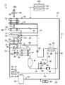
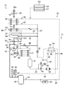
- FIG. 1 is a piping system diagram showing a refrigerant circuit of a container refrigeration apparatus according to this embodiment.
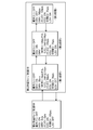
- FIG. 2 is a block diagram illustrating a determination operation according to the present embodiment.
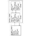
- FIG. 3 is a block diagram showing refrigerant charge control during the heating operation according to the present embodiment.
- FIG. 4 is a block diagram showing the refrigerant charge control in the defrost operation according to the present embodiment.
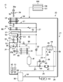
- FIG. 5 is a piping diagram showing the cooling operation of the cooling operation according to the present embodiment.
- FIG. 6 is a piping system diagram showing the cooling operation of the cooling operation according to the present embodiment.
- FIG. 7 is a piping diagram showing a heating operation and a defrost operation in the cooling operation according to the present embodiment.
- FIG. 1 is a piping system diagram showing a refrigerant circuit of a container refrigeration apparatus according to this embodiment.
- FIG. 2 is a block diagram illustrating a determination operation according to the present embodiment.
- FIG. 3 is
- FIG. 8 is a piping diagram illustrating the first refrigerant charge control according to the present embodiment.
- FIG. 9 is a piping diagram illustrating a first stage of second refrigerant charge control during the heating operation according to the present embodiment.
- FIG. 10 is a piping diagram illustrating a second stage of the second refrigerant charge control during the heating operation according to the present embodiment.
- FIG. 11 is a piping diagram illustrating a third stage of the second refrigerant charge control during the heating operation according to the present embodiment.
- the container refrigeration apparatus (10) of the present embodiment cools the interior of a container (not shown).
- the container refrigeration apparatus (10) also serves as a lid that closes the side opening surface of the container body.
- the container refrigeration apparatus (10) includes a refrigerant circuit (20) that circulates refrigerant and performs a cooling cycle.
- the refrigerant circuit (20) includes a main circuit (21), a hot gas bypass circuit (22), a reheat circuit (80), and a supercooling circuit (23).
- the main circuit (21) includes a compressor (30), a condenser (31), a main expansion valve (32), and an evaporator (33) connected in series by a refrigerant pipe in order.
- the compressor (30) has a motor (not shown) that drives the compression mechanism.
- the rotation speed of the motor of the compressor (30) is controlled in multiple stages by an inverter. That is, the compressor (30) is configured such that the operating rotational speed N is variable.
- the condenser (31) and the evaporator (33) are both fin-and-tube heat exchangers.
- the condenser (31) is arranged outside the warehouse. In the condenser (31), heat is exchanged between the outside air and the refrigerant.
- the evaporator (33) is arrange
- a drain pan (37) is provided below the evaporator (33).
- the drain pan (37) is formed in a flat container shape whose upper side is open. Inside the drain pan (37), frost and ice blocks that have fallen off from the evaporator (33), condensed water condensed from the air, and the like are collected.
- the main expansion valve (32) is configured such that the opening degree can be adjusted in multiple stages by a pulse motor.
- the main expansion valve (32) constitutes the main EV in FIGS.
- the condenser (31) is provided with an external fan (35), while the evaporator (33) is provided with an internal fan (36).
- the internal fan (36) is configured to supply the cooling air cooled by the evaporator (33) into the internal space.
- the external fan (35) and the internal fan (36) are provided with an external fan motor (35a) and an internal fan motor (36a), respectively.
- a fourth open / close valve (38) and a check valve (CV) are sequentially provided in the high-pressure gas pipe (24) between the compressor (30) and the condenser (31).
- the fourth on-off valve (38) is configured such that the opening degree can be adjusted in multiple stages by a pulse motor.
- the fourth on-off valve (38) constitutes the DMV in FIGS.
- the check valve (CV) allows the refrigerant to flow in the direction of the arrow shown in FIG. 1 and prohibits the reverse flow.
- the high pressure liquid pipe (25) between the condenser (31) and the main expansion valve (32) includes a receiver (41), a second on-off valve (49), a dryer (43), and a supercooling heat exchanger ( 44) and so on.
- the receiver (41) is provided on the downstream side of the condenser (31), and is configured to allow the refrigerant that has flowed through the condenser (31) to flow into the saturated liquid and the saturated gas.
- the second on-off valve (49) is an openable / closable solenoid valve.
- the second on-off valve (49) constitutes the LSV in FIGS.
- the dryer (43) is configured to capture moisture in the liquid refrigerant that has flowed through the condenser (31).
- a liquid seal prevention pipe (90) connected to the downstream side of the main expansion valve (32) is connected to the upstream side of the condenser (31).
- the liquid seal prevention pipe (90) is provided with a liquid seal on-off valve (91).
- the supercooling heat exchanger (44) cools the liquid refrigerant that has flowed through the condenser (31).
- the supercooling heat exchanger (44) has a primary side passage (45) and a secondary side passage (46). That is, in the supercooling heat exchanger (44), the refrigerant flowing through the primary side passage (45) and the refrigerant flowing through the secondary side passage exchange heat.
- the primary side passage (45) is connected to the high-pressure liquid pipe (25) of the main circuit (21), and the secondary side passage (46) is connected to the supercooling branch pipe (26) of the supercooling circuit (23). Has been.
- the inflow end of the supercooling branch pipe (26) is connected between the receiver (41) and the second on-off valve (49) in the high-pressure liquid pipe (25).
- the outflow end of the supercooling branch pipe (26) is connected to a compression chamber (intermediate compression chamber) in the middle of compression (intermediate pressure state) of the compressor (30). That is, the subcooling branch pipe (26) is a passage through which a part of the liquid refrigerant in the high-pressure liquid pipe (25) is divided and flows into the intermediate compression chamber of the compressor (30).
- a first on-off valve (47) and a supercooling expansion valve (48) are provided on the inflow side of the secondary passage (46) in the supercooling branch pipe (26).
- the first on-off valve (47) is an openable / closable solenoid valve.
- the first on-off valve (47) constitutes the ESV in FIGS.
- the supercooling expansion valve (48) can be adjusted in multiple stages by a pulse motor, and constitutes a decompression mechanism for decompressing the refrigerant.
- the supercooling expansion valve (48) constitutes the intermediate EV in FIGS.
- the hot gas bypass circuit (22) has one main passage (50) and two branch passages (51, 52) branched from the main passage (50).
- the two branch passages (51, 52) refer to a first branch passage (51) and a second branch passage (52).
- the inflow end of the main passage (50) is connected between the fourth on-off valve (38) in the high-pressure gas pipe (24) and the discharge side of the compressor (30).
- a third on-off valve (53) is provided in the main passage (50).
- the third on-off valve (53) is an openable / closable solenoid valve.
- the third on-off valve (53) constitutes the HSV in FIGS.
- the first branch passage (51) has one end connected to the outflow end of the main passage (50) and the other end connected to the low-pressure liquid pipe (27) between the main expansion valve (32) and the evaporator (33). It is connected.
- the second branch passage (52) has one end connected to the outflow end of the main passage (50) and the other end connected to the low-pressure liquid pipe (27).
- the second branch passage (52) is composed of a refrigerant pipe that is longer than the first branch passage (51).
- the second branch passage (52) has a drain pan heater (54) arranged meandering along the bottom of the drain pan (37).
- the drain pan heater (54) is configured to heat the inside of the drain pan (37) with a refrigerant.
- the hot gas bypass circuit (22) supplies the refrigerant compressed by the compressor (30) (the high-temperature gas refrigerant discharged from the compressor (30)) to the evaporator (33).
- a bypass circuit is configured.
- the reheat circuit (80) has a reheat passage (82).
- the inflow end of the reheat passage (82) is connected between the fourth on-off valve (38) in the high-pressure gas pipe (24) and the discharge side of the compressor (30).
- the reheat passage (82) is provided with a fifth on-off valve (81).
- the fifth on-off valve (81) is an openable / closable solenoid valve.
- the reheat passage (82) has a reheat heat exchanger (83) and a capillary tube. In the dehumidifying operation, the reheat heat exchanger (83) exchanges heat between the discharged refrigerant that has flowed in and the air that has been cooled and dehumidified by the evaporator (33), and heats the air. .
- the reheat heat exchanger (83) is a fin-and-tube heat exchanger.
- the capillary tube decompresses the refrigerant that has flowed out of the reheat heat exchanger (83).
- the reheat circuit (80) supplies a part of the refrigerant (high-temperature gas refrigerant discharged from the compressor (30)) compressed by the compressor (30) to the reheat heat exchanger (83).
- the circuit for doing is comprised. Note that the description of the dehumidifying operation is omitted.
- the refrigerant circuit (20) is also provided with various sensors.
- the high pressure gas pipe (24) is provided with a high pressure sensor (60), a high pressure switch (61), and a discharge temperature sensor (62).
- the high pressure sensor (60) detects the pressure of the high pressure gas refrigerant discharged from the compressor (30).
- the discharge temperature sensor (62) detects the temperature of the high-pressure gas refrigerant discharged from the compressor (30).
- the low pressure gas pipe (28) between the evaporator (33) and the compressor (30) is provided with a low pressure sensor (63) and a suction temperature sensor (64).
- the low pressure sensor (63) detects the pressure of the low pressure gas refrigerant sucked into the compressor (30).
- the suction temperature sensor (64) detects the temperature of the low-pressure gas refrigerant sucked into the compressor (30).
- the subcooling branch pipe (26) is provided with an inflow temperature sensor (65) on the inflow side of the secondary side passage (46) and an outflow temperature sensor (66) on the outflow side of the secondary side passage (46). It has been.
- the inflow temperature sensor (65) detects the temperature of the refrigerant immediately before flowing into the secondary side passage (46).
- the outflow temperature sensor (66) detects the temperature of the refrigerant immediately after flowing out of the secondary side passage (46).
- the low-pressure liquid pipe (27) is provided with an inflow temperature sensor (67) on the inflow side of the evaporator (33).
- the inflow temperature sensor (67) detects the temperature of the refrigerant immediately before flowing into the evaporator (33).
- the low pressure gas pipe (28) is provided with an outflow temperature sensor (68) on the outflow side of the evaporator (33).
- the outflow temperature sensor (68) detects the temperature of the refrigerant immediately after flowing out of the evaporator (33).
- an outside air temperature sensor (69) is provided on the suction side of the condenser (31).
- the outside air temperature sensor (69) detects the temperature of the outside air just before being sucked into the condenser (31) (that is, the temperature of the outside air).
- a suction temperature sensor (70) is provided on the suction side of the evaporator (33), and an outlet temperature sensor (71) is provided on the outlet side of the evaporator (33).
- the suction temperature sensor (70) detects the temperature of the internal air immediately before passing through the evaporator (33).
- the blowing temperature sensor (71) detects the temperature of the internal air immediately after passing through the evaporator (33) (the blowing air temperature SS).
- the container refrigeration apparatus (10) is provided with a controller (100) as a control unit for controlling the refrigerant circuit (20).
- the controller (100) includes a refrigerant amount determination unit (106) that determines whether or not the refrigerant amount of the refrigerant circuit (20) is insufficient in the heating operation or the defrost operation of the cooling operation, and the refrigerant amount determination unit (106 ) And a refrigerant amount adjusting unit (107) for replenishing (charging) the refrigerant in the circulation flow of the refrigerant circuit (20).
- the heating operation and the defrost operation in the cooling operation constitute a bypass operation according to the present invention.
- the refrigerant amount determination unit (106) performs determination 1 and determination 2, as shown in FIG.
- determination 1 it is determined that the temperature of the refrigerant discharged from the compressor (30) is abnormally high, and refrigerant charge control is performed.
- the condition of the determination 2 it is determined that the temperature of the refrigerant discharged from the compressor (30) is an appropriate temperature, and the operation returns to the cooling operation or the defrost operation.
- the determination 1 when the state corresponding to the pressure equivalent saturation temperature HP (T) of the high-pressure refrigerant is too low and the superheat degree SH (DCHS-HP (T)) of the discharged refrigerant is 35 ° C. or more continues for 1 minute, and defrost During operation or heating operation, when the operation speed N of the compressor (30) reaches an upper limit value, it is determined that the temperature of the refrigerant discharged from the compressor (30) is abnormally high.
- the 35 ° C. constitutes a predetermined value related to the superheat degree SH of the compressed refrigerant according to the present invention, and the one minute constitutes a predetermined time related to the superheat degree SH of the compressed refrigerant according to the present invention.
- the superheat degree SH of the discharged refrigerant can be reduced by increasing the operating speed N and increasing the refrigerant circulation amount.
- the superheat degree SH can be changed and stabilized more quickly than the refrigerant charge control. Therefore, when the operation speed N of the compressor (30) cannot be increased any more than the upper limit value, the superheat degree SH of the discharged refrigerant is reduced by performing the first refrigerant charge control.
- the determination 1 if the state corresponding to the pressure equivalent saturation temperature LP (T) of the low-pressure refrigerant is too low and the superheat degree SH (SGS-LP (T)) of the suction refrigerant is 25 ° C. or more continues for 3 minutes,
- the operation speed N of the compressor (30) reaches the upper limit value, it is determined that the temperature of the refrigerant discharged from the compressor (30) is abnormally high.
- the 25 ° C. constitutes a predetermined value related to the superheat degree SH of the suction refrigerant according to the present invention.
- the operation returns to the cooling operation or the defrost operation. That is, when the pressure (high pressure) HPT of the discharge refrigerant of the compressor (30) is 1500 kPa or more or the superheat degree SH (DCHS-HP (T)) of the discharge refrigerant is 10 ° C. or less, the compressor Returning to normal heating operation or defrost operation assuming that the discharge temperature of (30) becomes appropriate. In addition, when 5 minutes have passed since the refrigerant charge control was started, the normal heating operation or defrost operation is resumed.
- the value which shows the specific temperature condition, time condition, or pressure condition in the said determination 1 or 2 is an illustration, and is not limited to this.
- the refrigerant amount adjusting unit (107) adjusts the shortage of the refrigerant flow rate circulating in the refrigerant circuit (20). As shown in FIGS. 3 and 4, the refrigerant amount adjusting unit (107) performs first refrigerant charge control and second refrigerant charge control. 3 shows the refrigerant charge control during the heating operation, FIG. 4 shows the refrigerant charge control during the defrost operation, and the first refrigerant charge control of FIG. 3 and the first refrigerant charge control of FIG. It is.
- the third on-off valve (53), the first on-off valve (47), and the supercooling expansion valve (48) are opened during the heating operation or the defrost operation, and the fourth on-off valve (38).
- the liquid refrigerant in the receiver (41) passes through the supercooling branch pipe (26) and is a compression chamber in an intermediate pressure state in the compressor (30). To flow into.
- the second refrigerant charge control during the heating operation (FIG. 3) is performed in the first to third stages, and the second refrigerant charge control during the defrost operation (FIG. 4) is performed in the first to second stages. Is done.
- the compressor (30) is opened with the fourth on-off valve (38) slightly opened and the second on-off valve (49) closed.
- the discharged refrigerant (compressed refrigerant according to the present invention) is caused to flow into the high-pressure liquid pipe (25).
- pressure liquid pipe (25) increases, and a pressure becomes high.
- the second on-off valve (49) and the main expansion valve (32) that were closed in the first stage are fully opened, and the condenser (31)
- the high-pressure refrigerant accumulated in the receiver (41) and the high-pressure liquid pipe (25) flows through the second on-off valve (49) and the main expansion valve (32) to the evaporator (33).
- the 3rd on-off valve (53) opened in the 2nd step will be in a fully closed state, and the discharge refrigerant of compressor (30) will be a condenser ( 31), flows into the receiver (41) and the high-pressure liquid pipe (25).
- the second on-off valve (49) and the main expansion valve (32) are opened, the refrigerant accumulated in the condenser (31), the receiver (41), and the high-pressure liquid pipe (25) It flows through the second on-off valve (49) and the main expansion valve (32) to the evaporator (33).
- the fourth on-off valve (38) is slightly opened and the second on-off valve (49) and the main expansion valve (32) are closed.
- the supercooling expansion valve (48) is opened, and the refrigerant discharged from the compressor (30) (the compressed refrigerant according to the present invention) is caused to flow into the high-pressure liquid pipe (25).
- pressure liquid pipe (25) increases, and a pressure becomes high.
- the fourth on-off valve (38) is further opened from the state of the first stage.
- the refrigerant accumulated in the condenser (31), the receiver (41), and the high-pressure liquid pipe (25) passes through the supercooling branch pipe (26) to the compression chamber in the intermediate pressure state in the compressor (30). Inflow.
- the first stage during the heating operation and the defrost operation described above constitutes the refrigerant inflow operation according to the present invention
- the second to third stages during the heating operation constitute the first refrigerant replenishment operation according to the present invention
- the second stage during the defrost operation constitutes the second refrigerant supply operation according to the present invention.
- the operation of the container refrigeration apparatus (10) is roughly classified into “cooling operation” and “defrost operation”.
- the cooling operation is an operation for cooling the interior of the container to a relatively low temperature. That is, the cooling operation is an operation of refrigeration / cooling the inside of the warehouse in order to preserve the transported goods (for example, fresh food) accommodated in the container body.
- the refrigerant discharged from the compressor (30) is passed through the hot gas bypass circuit (22) to melt the frost adhering to the surface of the heat transfer tube of the evaporator (33) (defrosting). Driving).
- the defrost operation is executed, for example, every time a predetermined set time elapses from the start of the cooling operation, and the cooling operation is resumed after the defrost operation ends.
- the refrigerant compressed by the compressor (30) is condensed by the condenser (31) and then passes through the receiver (41).
- a part of the refrigerant that has passed through the receiver (41) flows through the low-pressure liquid pipe (27) as it is, and the rest is divided into the supercooling branch pipe (26).
- the refrigerant that has flowed through the low-pressure liquid pipe (27) is depressurized by the main expansion valve (32), and then flows through the evaporator (33).
- the evaporator (33) the refrigerant absorbs heat from the internal air and evaporates. Thereby, the air in a warehouse is cooled.
- the refrigerant evaporated in the evaporator (33) is sucked into the compressor (30) and compressed again.
- the refrigerant divided into the supercooling branch pipe (26) passes through the supercooling expansion valve (48) and is reduced to an intermediate pressure, and then passes through the secondary passage (46) of the supercooling heat exchanger (44). Flowing. In the supercooling heat exchanger (44), heat is exchanged between the refrigerant flowing through the primary passage (45) and the refrigerant flowing through the secondary passage (46). As a result, the refrigerant in the primary passage (45) is subcooled, while the refrigerant in the secondary passage (46) evaporates. The refrigerant that has flowed out of the secondary passage (46) is sucked into the compression chamber in the intermediate pressure state from the intermediate port of the compressor (30).
- the line from the fully closed main expansion valve (32) to the suction port of the compressor (30) ie, the low pressure liquid pipe (27) and the low pressure gas pipe (28)
- the refrigerant is sucked into the compressor (30).
- the refrigerant discharged from the compressor (30) is condensed in the condenser (31) to be in a liquid state and stored in the receiver (41). Thereby, in the pump-down operation, the refrigerant in the refrigerant circuit (20) is collected in the receiver (41).
- the operating speed N (operating frequency) of the compressor (30) is controlled to be constant in principle. Moreover, the rotation speed of the outside fan (35) becomes the maximum rotation speed. Thereby, the condensation of the refrigerant is promoted in the condenser.
- This heating operation is executed when the temperature inside the container is lower than the target temperature and the inside of the container is excessively cooled.
- a pump-down operation is performed immediately before the heating operation.
- the second on-off valve (49) is closed and the third on-off valve (53) is opened.
- the main expansion valve (32) is fully closed (0 pulse).
- the first on-off valve (47), the fourth on-off valve (38), the fifth on-off valve (81) and the supercooling expansion valve (48) are in a fully closed state (0 pulse) in principle. Then, while the compressor (30) and the internal fan (36) are operated, the external fan (35) is basically stopped.
- the refrigerant compressed by the compressor (30) is supplied to the evaporator (33) via the hot gas bypass circuit (22). Specifically, the high-temperature and high-pressure gas refrigerant flows through the main circuit (21) and then splits into the first branch passage (51) and the second branch passage (52). The refrigerant branched to the second branch passage (52) passes through the drain pan heater (54) and then merges with the refrigerant flowing out of the first branch passage (51). The combined refrigerant flows to the evaporator (33). In the evaporator (33), the refrigerant dissipates heat to the internal air. As a result, the internal air is heated, so that the internal temperature can be brought close to the target temperature. The refrigerant radiated by the evaporator (33) is sucked into the compressor (30) and compressed.
- the high-temperature and high-pressure gas refrigerant compressed by the compressor (30) is converted into a condenser (31), a receiver (41), a supercooling heat exchanger (44), and a main expansion valve.
- This is an operation of bypassing (32) and supplying directly to the evaporator (33).
- the third on-off valve (53) is opened, the second on-off valve (49) is fully closed (0 pulse), the first on-off valve (47), the fourth on-off valve (38), the fifth The on-off valve (81) and the supercooling expansion valve (48) are in a fully closed state (0 pulse) in principle.
- the compressor (30) starts operation, and the outside fan (35) and the inside fan (36) are stopped in principle.
- the refrigerant compressed by the compressor (30) is supplied to the evaporator (33) via the hot gas bypass circuit (22). Specifically, after the high-pressure gas refrigerant flows through the main circuit (21), it passes through the third on-off valve (53) and is divided into the first branch passage (51) and the second branch passage (52). The refrigerant branched to the second branch passage (52) passes through the drain pan heater (54). Here, in the drain pan (37), ice blocks and the like peeled off from the surface of the evaporator (33) are collected. The ice blocks and the like are heated and melted by the refrigerant flowing inside the drain pan heater (54). The melted water is discharged out of the warehouse through a predetermined channel.
- the refrigerant that has flowed out of the drain pan heater (54) merges with the refrigerant that has passed through the first branch passage (51), and flows through the evaporator (33).
- a high-pressure gas refrigerant (so-called hot gas) flows through the heat transfer tube.
- hot gas a high-pressure gas refrigerant
- surroundings of a heat exchanger tube is gradually heated from the inside with a refrigerant
- the frost adhering to the evaporator (33) is gradually collected in the drain pan (37).
- the refrigerant used for defrosting of the evaporator (33) is sucked into the compressor (30) and compressed.
- the high pressure discharge pressure of the compressor (30)
- the high pressure constant control is performed.
- the operating speed of the compressor (30) during the defrost operation is higher than the operating speed of the compressor (30) during the heating operation.
- the refrigerant amount adjusting unit (107) determines whether to perform the first refrigerant charge control or the second refrigerant charge control based on the outside air temperature (the detected value of the outside air temperature sensor (69)). Specifically, as shown in FIG. 5, in the heating operation, the first refrigerant charge control is performed when the outside air temperature is ⁇ 5 ° C. or higher (broken line A), and the second refrigerant when the outside air temperature is less than ⁇ 5 ° C. Charge control is performed (broken line B). In the case of the defrost operation, as shown in FIG. 5, the first refrigerant charge control is performed when the outside air temperature is 10 ° C. or higher (solid line C), and the second refrigerant charge control is performed when the outside air temperature is less than 10 ° C. ( Solid line D).
- the first on-off valve (47) and the supercooling expansion valve (48) are opened by the refrigerant amount adjusting unit (107).
- the fourth on-off valve (38) is in the closed state (0 pulse), and the outside fan (35) remains stopped.
- the third on-off valve (53) is in an open state, and the second on-off valve (49) and the main expansion valve (32) are in a closed state.
- the liquid refrigerant accumulated in the receiver (41) flows into the compression chamber in the intermediate pressure state in the compressor (30) through the supercooling branch pipe (26). As a result, as shown in FIG.
- HP (T) is a pressure equivalent saturation temperature of the discharge refrigerant (high pressure refrigerant) of the compressor (30)
- DCHS is a temperature detected by the discharge temperature sensor (62).
- LP (T) is the saturation temperature corresponding to the pressure of the suction refrigerant (low pressure refrigerant) of the compressor (30)
- SGS is the temperature detected by the suction temperature sensor (64).
- HPT is the pressure of the refrigerant (high-pressure refrigerant) discharged from the compressor (30).
- the first refrigerant charge control is performed when the outside air temperature is relatively high as described above.
- the refrigerant pressure in the high-pressure liquid pipe (25) is relatively high, and compression of the intermediate pressure state in the high-pressure liquid pipe (25) and the compressor (30) that is the charge (replenishment) destination A sufficient pressure difference from the chamber can be secured. Therefore, the refrigerant in the high-pressure liquid pipe (25) can be easily flowed to the compressor (30) by the pressure difference only by opening the first on-off valve (47) and the supercooling expansion valve (48).
- the refrigerant amount determination unit (106) determines that the refrigerant flow rate is appropriate by satisfying the condition of determination 2 after the first refrigerant charge control, the normal heating operation or defrost operation shown in FIG. 7 is resumed. That is, when the pressure (high pressure) HPT of the discharge refrigerant of the compressor (30) is 1500 kPa or more, or the superheat degree SH (DCHS-HP (T)) of the discharge refrigerant is 10 ° C. or less, the compressor ( Assuming that the temperature of the refrigerant discharged in 30) is appropriate, the normal heating operation or defrosting operation is resumed. Also, when 5 minutes have passed since entering the refrigerant charge control, the normal heating operation or defrosting operation is resumed.
- the second refrigerant charge control is performed as shown in FIGS. Is done.
- the refrigerant valve controller (107) opens the fourth on-off valve (38) to an opening of 30 pulses, and the main expansion valve (32) to 55 pulses. Opened and the second on-off valve (49) is closed. Then, the supercooling expansion valve (48) is throttled to 70 pulses. At this time, the first on-off valve (47) and the third on-off valve (53) are in an open state, and the outside fan (35) remains stopped.
- the fourth on-off valve (38) is opened up to 150 pulses at the maximum every 30 pulses every 5 seconds. By doing so, as shown in FIG.
- the high-temperature and high-pressure gas refrigerant discharged from the compressor (30) passes from the fourth on-off valve (38) to the condenser (31), the receiver (41), and the high-pressure liquid pipe ( Compressed refrigerant flows into 25) and the pressure of the accumulated refrigerant increases.
- the second refrigerant charge control proceeds to the second stage.
- the refrigerant amount adjusting unit (107) opens the fourth on-off valve (38) by 100 pulses every 5 seconds, up to 350 pulses. Further, the main expansion valve (32) is opened up to 100 pulses, and the second on-off valve (49) is opened.
- the refrigerant accumulated in the condenser (31), the receiver (41), and the high-pressure liquid pipe (25) becomes the second on-off valve (49) and the main expansion valve (32).
- the second refrigerant charge control proceeds to the third stage.
- the refrigerant amount adjusting unit (107) opens the fourth on-off valve (38) up to 760 pulses, and the third on-off valve (53) is fully closed. . That is, the refrigerant circuit (20) is in the same state as the cooling operation of the cooling operation. In this third stage, as shown in FIG.
- the high-temperature and high-pressure gas refrigerant discharged from the compressor (30), together with the refrigerant accumulated in the condenser (31), receiver (41), and high-pressure liquid pipe (25), is discharged from the main expansion valve (32) to the evaporator. Since it is supplied to (33), the flow rate of the refrigerant flowing through the evaporator (33) increases. For this reason, the refrigerating machine oil remaining in the evaporator (33) can be reliably recovered.
- the refrigerant amount adjusting unit (107) opens the fourth on-off valve (38) to an opening of 30 pulses, and the main expansion valve (32) and the second on-off valve are opened and closed.
- the valve (49) is closed.
- the supercooling expansion valve (48) opens up to 200 pulses.
- the first on-off valve (47) and the third on-off valve (53) are in an open state, and the outside fan (35) remains stopped.
- the fourth on-off valve (38) is opened up to 150 pulses at the maximum every 30 pulses every 5 seconds.
- the high-temperature and high-pressure gas refrigerant discharged from the compressor (30) is discharged from the fourth on-off valve (38) to the condenser (31 ),
- the compressed refrigerant flows into the receiver (41) and the high-pressure liquid pipe (25), and the pressure of the accumulated refrigerant increases.
- the second refrigerant charge control proceeds to the second stage.
- the second stage of the second refrigerant charge control during the defrost operation is the same state as the first stage except for the fourth on-off valve (38).
- the fourth on-off valve (38) is opened up to 350 pulses at the maximum by 100 pulses every 5 seconds by the refrigerant amount adjusting unit (107).
- the refrigerant accumulated in the condenser (31), the receiver (41), and the high-pressure liquid pipe (25) flows into the first on-off valve (47) and the supercooling expansion valve (48). ), That is, through the supercooling branch pipe (26), flows into the compression chamber in the intermediate pressure state in the compressor (30).
- the refrigerant in the high-pressure liquid pipe (25) is charged (supplemented) into the refrigerant circulation in the defrost operation, and the refrigerant flow rate during the defrost operation increases.
- the superheat degree SH of the refrigerant discharged from the compressor (30) is lowered, and the refrigeration oil remaining in the evaporator (33) is reliably recovered. Is done.
- the second refrigerant charge control is performed when the outside air temperature is relatively low as described above (that is, when the outside air is low). At low outside air, the refrigerant pressure in the high-pressure liquid pipe (25) is low, and in this state, the high-pressure liquid pipe (25) and the evaporator (33) and compressor (30) that are the charge (replenishment) destination A sufficient pressure difference from the compression chamber in the intermediate pressure state cannot be secured. If it does so, a sufficient quantity of refrigerant
- the refrigerant pressure in the high-pressure liquid pipe (25) is increased (the first stage is performed) before charging the refrigerant. Even at that time, the pressure difference can be secured, and a sufficient amount of refrigerant can be charged.
- the refrigerant inflow operation (the first stage of the second refrigerant charge control) for causing the compressed refrigerant to flow into the high-pressure liquid pipe (25) in the heating operation and the defrost operation at the time of low outside air with a low outside air temperature. Since the refrigerant pressure in the high-pressure liquid pipe (25) is increased, intermediate pressure compression is performed in the high-pressure liquid pipe (25) and the evaporator (33) or compressor (30) that is the charge (replenishment) destination. A sufficient pressure difference from the chamber can be secured.
- the refrigerant in the high pressure liquid pipe (25) can be reliably charged (supplemented) into the refrigerant circulation in the heating operation and defrost operation. .
- the refrigerant in the high-pressure liquid pipe (25) is caused to flow from the main expansion valve (32) to the evaporator (33), the high-pressure refrigerant can be allowed to flow into the evaporator (33). Thereby, the refrigeration oil remaining in the evaporator (33) can be reliably recovered.
- the operating speed of the compressor (30) is higher and the high pressure (discharge pressure of the compressor (30)) is higher than in the heating operation in order to increase the defrosting capacity. Therefore, the refrigerant pressure in the high pressure liquid pipe (25) is higher in the refrigerant inflow operation in the defrost operation than in the refrigerant inflow operation in the heating operation. Therefore, in the defrost operation, if the refrigerant replenishment operation is performed in which the refrigerant in the high-pressure liquid pipe (25) flows into the evaporator (33) through the main expansion valve (32) as in the heating operation, the refrigerant is excessively replenished. End up.
- the refrigerant in the high pressure liquid pipe (25) is passed through the supercooling branch pipe (26) in the compressor (30). It flows into the compression chamber in the intermediate pressure state. Since the inflow portion of the refrigerant into the compression chamber is provided with a resistance so that a large amount of refrigerant does not flow, it is possible to prevent the refrigerant from being replenished excessively. As a result, oil leakage in the compressor (30) can be prevented, leading to improved reliability. That is, in the defrost operation, the refrigerant replenishment amount can be made appropriate by performing the refrigerant replenishment operation of flowing the refrigerant in the high pressure liquid pipe (25) into the compression chamber in the intermediate pressure state in the compressor (30).
- the refrigerant inflow operation can be performed when the refrigerant is surely short in the heating operation and the defrost operation.
- the refrigerant inflow operation is performed when the operating speed N of the compressor (30) reaches the upper limit during the defrost operation, the refrigerant inflow occurs when the refrigerant is surely in a shortage state during the defrost operation.
- the action can be performed.
- the refrigerant inflow operation is performed when the operation rotational speed N of the compressor (30) reaches the upper limit, and therefore the refrigerant is surely in a shortage state during the heating operation.
- the refrigerant inflow operation can be performed.
- the superheat degree SH of the refrigerant sucked in the compressor (30) becomes 25 ° C. or higher, a part of the high-temperature high-pressure gas refrigerant discharged from the compressor (30) is a high-pressure liquid containing the condenser (31). Since it is made to flow into the pipe (25), the pressure of the refrigerant in the high-pressure liquid pipe (25) can be increased. For this reason, the compressed refrigerant of the compressor (30) is supplied to the circulating flow returning to the compressor (30) through the hot gas bypass circuit (22) and the evaporator (33) without leaving the refrigerant of the high-pressure liquid pipe (25). be able to. Thereby, since the refrigerant
- the present invention may be configured as follows for the above embodiment.
- the same control as the second refrigerant charge control (FIG. 3) during the heating operation may be added as the third refrigerant charge control. That is, in the defrost operation, the refrigerant amount adjustment unit (107) determines which of the first refrigerant charge control to the third refrigerant charge control is performed based on the outside air temperature. Specifically, as described above, the second refrigerant charge control may be performed when the outside air temperature is less than 10 ° C., and the third refrigerant charge control may be performed when the outside air temperature is less than ⁇ 30 ° C.
- the second refrigerant charge control (FIG. 4) may be changed to the same control as the second refrigerant charge control (FIG. 3) during the heating operation.
- the present invention is useful for a container refrigeration apparatus.
- Refrigerant circuit 20 Refrigerant circuit 22 Hot gas bypass circuit 30 Compressor 31 Condenser 32 Expansion valve 33 Evaporator 107 Refrigerant amount adjustment unit
Abstract
La présente invention se rapporte à un dispositif de réfrigération (10) pour un récipient, ledit dispositif de réfrigération étant pourvu d'un circuit de réfrigération (20) qui effectue un cycle de réfrigération et qui comprend un circuit de dérivation de gaz chaud (22) et est conçu pour effectuer une opération de dérivation pendant laquelle un fluide frigorigène comprimé provenant d'un compresseur (30) est amené à passer à travers le circuit de dérivation de gaz chaud (22) et à circuler dans un évaporateur (33). On utilise une unité de réglage de la quantité de fluide frigorigène (107) qui, pendant l'opération de dérivation, peut effectuer une action de mise en circulation du fluide frigorigène pour amener une partie du fluide frigorigène comprimé provenant du compresseur (20) à circuler dans un tuyau pour fluide haute pression (25) qui comprend un condensateur (31), ainsi qu'une action de remplissage de fluide frigorigène pour amener le fluide frigorigène provenant du tuyau pour fluide haute pression (25) à circuler dans l'évaporateur (33) après l'action de mise en circulation du fluide frigorigène.
Applications Claiming Priority (2)
| Application Number | Priority Date | Filing Date | Title |
|---|---|---|---|
| JP2011270624 | 2011-12-09 | ||
| JP2011-270624 | 2011-12-09 |
Publications (1)
| Publication Number | Publication Date |
|---|---|
| WO2013084510A1 true WO2013084510A1 (fr) | 2013-06-13 |
Family
ID=48573897
Family Applications (1)
| Application Number | Title | Priority Date | Filing Date |
|---|---|---|---|
| PCT/JP2012/007874 WO2013084510A1 (fr) | 2011-12-09 | 2012-12-10 | Dispositif de réfrigération pour un récipient |
Country Status (2)
| Country | Link |
|---|---|
| JP (1) | JP2013140002A (fr) |
| WO (1) | WO2013084510A1 (fr) |
Cited By (1)
| Publication number | Priority date | Publication date | Assignee | Title |
|---|---|---|---|---|
| US20200400357A1 (en) * | 2015-02-24 | 2020-12-24 | Walmart Apollo, Llc | Refrigeration heat reclaim |
Families Citing this family (4)
| Publication number | Priority date | Publication date | Assignee | Title |
|---|---|---|---|---|
| DK3222942T3 (da) | 2014-11-28 | 2022-04-19 | Daikin Ind Ltd | Køleapparat til beholder |
| JP6173360B2 (ja) * | 2015-01-07 | 2017-08-02 | 三菱電機株式会社 | 冷凍装置 |
| JP6404727B2 (ja) * | 2015-01-28 | 2018-10-17 | ヤンマー株式会社 | ヒートポンプ |
| JP6274277B2 (ja) * | 2015-09-30 | 2018-02-07 | ダイキン工業株式会社 | 冷凍装置 |
Citations (5)
| Publication number | Priority date | Publication date | Assignee | Title |
|---|---|---|---|---|
| JPH0424478A (ja) * | 1990-05-17 | 1992-01-28 | Daikin Ind Ltd | 冷凍装置 |
| JP2007071505A (ja) * | 2005-09-09 | 2007-03-22 | Daikin Ind Ltd | 冷凍装置 |
| JP2008128570A (ja) * | 2006-11-21 | 2008-06-05 | Mitsubishi Heavy Ind Ltd | 冷凍装置 |
| JP2010281532A (ja) * | 2009-06-05 | 2010-12-16 | Daikin Ind Ltd | トレーラ用冷凍装置 |
| JP2011112268A (ja) * | 2009-11-25 | 2011-06-09 | Daikin Industries Ltd | コンテナ用冷凍装置 |
-
2012
- 2012-12-10 JP JP2012269222A patent/JP2013140002A/ja active Pending
- 2012-12-10 WO PCT/JP2012/007874 patent/WO2013084510A1/fr active Application Filing
Patent Citations (5)
| Publication number | Priority date | Publication date | Assignee | Title |
|---|---|---|---|---|
| JPH0424478A (ja) * | 1990-05-17 | 1992-01-28 | Daikin Ind Ltd | 冷凍装置 |
| JP2007071505A (ja) * | 2005-09-09 | 2007-03-22 | Daikin Ind Ltd | 冷凍装置 |
| JP2008128570A (ja) * | 2006-11-21 | 2008-06-05 | Mitsubishi Heavy Ind Ltd | 冷凍装置 |
| JP2010281532A (ja) * | 2009-06-05 | 2010-12-16 | Daikin Ind Ltd | トレーラ用冷凍装置 |
| JP2011112268A (ja) * | 2009-11-25 | 2011-06-09 | Daikin Industries Ltd | コンテナ用冷凍装置 |
Cited By (1)
| Publication number | Priority date | Publication date | Assignee | Title |
|---|---|---|---|---|
| US20200400357A1 (en) * | 2015-02-24 | 2020-12-24 | Walmart Apollo, Llc | Refrigeration heat reclaim |
Also Published As
| Publication number | Publication date |
|---|---|
| JP2013140002A (ja) | 2013-07-18 |
Similar Documents
| Publication | Publication Date | Title |
|---|---|---|
| JP4770976B2 (ja) | コンテナ用冷凍装置 | |
| JP4831247B2 (ja) | コンテナ用冷凍装置 | |
| JP2011252702A5 (fr) | ||
| US11384965B2 (en) | Refrigeration cycle apparatus performing a refrigerant circulation operation using a liquid pump | |
| JP2010532462A (ja) | 高温ガス霜取り方法および装置 | |
| JP2008096033A (ja) | 冷凍装置 | |
| JP5472391B2 (ja) | コンテナ用冷凍装置 | |
| WO2013084510A1 (fr) | Dispositif de réfrigération pour un récipient | |
| JP6545252B2 (ja) | 冷凍サイクル装置 | |
| WO2020066273A1 (fr) | Dispositif de pompe à chaleur | |
| JP5404761B2 (ja) | 冷凍装置 | |
| JP2009109110A (ja) | 冷凍装置 | |
| JP5370551B1 (ja) | コンテナ用冷凍装置 | |
| JP5445577B2 (ja) | 冷凍装置およびその異冷媒充填検出方法 | |
| JP2011099626A (ja) | 冷凍サイクル装置及びそれを用いた温水暖房装置 | |
| JP2011158144A (ja) | 冷凍装置 | |
| JP6173360B2 (ja) | 冷凍装置 | |
| JP2008045796A (ja) | 冷凍装置 | |
| JP5544840B2 (ja) | コンテナ用冷凍装置 | |
| JP6146428B2 (ja) | 冷凍装置 | |
| JP2013122333A (ja) | コンテナ用冷凍装置 | |
| JP2018173194A5 (fr) | ||
| JP2004162998A (ja) | 車両用冷凍装置、およびその制御方法 | |
| JP7331021B2 (ja) | 冷凍サイクル装置 | |
| KR20100088378A (ko) | 공기조화기 및 공기조화기의 제상운전방법 |
Legal Events
| Date | Code | Title | Description |
|---|---|---|---|
| 121 | Ep: the epo has been informed by wipo that ep was designated in this application |
Ref document number: 12854961 Country of ref document: EP Kind code of ref document: A1 |
|
| NENP | Non-entry into the national phase |
Ref country code: DE |
|
| 122 | Ep: pct application non-entry in european phase |
Ref document number: 12854961 Country of ref document: EP Kind code of ref document: A1 |