WO2013073291A1 - 媒体処理装置 - Google Patents
媒体処理装置 Download PDFInfo
- Publication number
- WO2013073291A1 WO2013073291A1 PCT/JP2012/074567 JP2012074567W WO2013073291A1 WO 2013073291 A1 WO2013073291 A1 WO 2013073291A1 JP 2012074567 W JP2012074567 W JP 2012074567W WO 2013073291 A1 WO2013073291 A1 WO 2013073291A1
- Authority
- WO
- WIPO (PCT)
- Prior art keywords
- gear
- operation knob
- unit
- temporary storage
- storage unit
- Prior art date
- Legal status (The legal status is an assumption and is not a legal conclusion. Google has not performed a legal analysis and makes no representation as to the accuracy of the status listed.)
- Ceased
Links
Images


Classifications
-
- B—PERFORMING OPERATIONS; TRANSPORTING
- B65—CONVEYING; PACKING; STORING; HANDLING THIN OR FILAMENTARY MATERIAL
- B65H—HANDLING THIN OR FILAMENTARY MATERIAL, e.g. SHEETS, WEBS, CABLES
- B65H5/00—Feeding articles separated from piles; Feeding articles to machines
-
- B—PERFORMING OPERATIONS; TRANSPORTING
- B65—CONVEYING; PACKING; STORING; HANDLING THIN OR FILAMENTARY MATERIAL
- B65H—HANDLING THIN OR FILAMENTARY MATERIAL, e.g. SHEETS, WEBS, CABLES
- B65H29/00—Delivering or advancing articles from machines; Advancing articles to or into piles
- B65H29/006—Winding articles into rolls
-
- G—PHYSICS
- G07—CHECKING-DEVICES
- G07D—HANDLING OF COINS OR VALUABLE PAPERS, e.g. TESTING, SORTING BY DENOMINATIONS, COUNTING, DISPENSING, CHANGING OR DEPOSITING
- G07D11/00—Devices accepting coins; Devices accepting, dispensing, sorting or counting valuable papers
- G07D11/40—Device architecture, e.g. modular construction
-
- B—PERFORMING OPERATIONS; TRANSPORTING
- B65—CONVEYING; PACKING; STORING; HANDLING THIN OR FILAMENTARY MATERIAL
- B65H—HANDLING THIN OR FILAMENTARY MATERIAL, e.g. SHEETS, WEBS, CABLES
- B65H2301/00—Handling processes for sheets or webs
- B65H2301/40—Type of handling process
- B65H2301/41—Winding, unwinding
- B65H2301/419—Winding, unwinding from or to storage, i.e. the storage integrating winding or unwinding means
- B65H2301/4191—Winding, unwinding from or to storage, i.e. the storage integrating winding or unwinding means for handling articles of limited length, e.g. AO format, arranged at intervals from each other
-
- B—PERFORMING OPERATIONS; TRANSPORTING
- B65—CONVEYING; PACKING; STORING; HANDLING THIN OR FILAMENTARY MATERIAL
- B65H—HANDLING THIN OR FILAMENTARY MATERIAL, e.g. SHEETS, WEBS, CABLES
- B65H2402/00—Constructional details of the handling apparatus
- B65H2402/40—Details of frames, housings or mountings of the whole handling apparatus
- B65H2402/44—Housings
- B65H2402/441—Housings movable for facilitating access to area inside the housing, e.g. pivoting or sliding
-
- B—PERFORMING OPERATIONS; TRANSPORTING
- B65—CONVEYING; PACKING; STORING; HANDLING THIN OR FILAMENTARY MATERIAL
- B65H—HANDLING THIN OR FILAMENTARY MATERIAL, e.g. SHEETS, WEBS, CABLES
- B65H2403/00—Power transmission; Driving means
- B65H2403/40—Toothed gearings
-
- B—PERFORMING OPERATIONS; TRANSPORTING
- B65—CONVEYING; PACKING; STORING; HANDLING THIN OR FILAMENTARY MATERIAL
- B65H—HANDLING THIN OR FILAMENTARY MATERIAL, e.g. SHEETS, WEBS, CABLES
- B65H2403/00—Power transmission; Driving means
- B65H2403/90—Machine drive
- B65H2403/94—Other features of machine drive
- B65H2403/944—Multiple power sources for one mechanism
-
- B—PERFORMING OPERATIONS; TRANSPORTING
- B65—CONVEYING; PACKING; STORING; HANDLING THIN OR FILAMENTARY MATERIAL
- B65H—HANDLING THIN OR FILAMENTARY MATERIAL, e.g. SHEETS, WEBS, CABLES
- B65H2407/00—Means not provided for in groups B65H2220/00 – B65H2406/00 specially adapted for particular purposes
- B65H2407/10—Safety means, e.g. for preventing injuries or illegal operations
-
- B—PERFORMING OPERATIONS; TRANSPORTING
- B65—CONVEYING; PACKING; STORING; HANDLING THIN OR FILAMENTARY MATERIAL
- B65H—HANDLING THIN OR FILAMENTARY MATERIAL, e.g. SHEETS, WEBS, CABLES
- B65H2407/00—Means not provided for in groups B65H2220/00 – B65H2406/00 specially adapted for particular purposes
- B65H2407/20—Means not provided for in groups B65H2220/00 – B65H2406/00 specially adapted for particular purposes for manual intervention of operator
-
- B—PERFORMING OPERATIONS; TRANSPORTING
- B65—CONVEYING; PACKING; STORING; HANDLING THIN OR FILAMENTARY MATERIAL
- B65H—HANDLING THIN OR FILAMENTARY MATERIAL, e.g. SHEETS, WEBS, CABLES
- B65H2701/00—Handled material; Storage means
- B65H2701/10—Handled articles or webs
- B65H2701/19—Specific article or web
- B65H2701/1912—Banknotes, bills and cheques or the like
Definitions
- the present invention relates to a medium processing apparatus, for example, an automatic teller machine (ATM) that performs a desired transaction by inserting a medium such as banknotes.
- ATM automatic teller machine
- automatic teller machines used in financial institutions, etc. are configured to allow customers to deposit cash such as banknotes and coins, and to withdraw cash from customers according to the transaction details with the customer. Has been.
- a banknote deposit / withdrawal port for receiving and receiving banknotes with customers
- a discrimination unit for discriminating the denomination and authenticity of inserted banknotes
- temporarily holding inserted banknotes The thing which has a temporary storage part to perform and the denomination cassette which stores a banknote for every denomination is proposed (for example, refer FIG. 1 of patent 3207504 gazette).
- This automatic teller machine in a deposit transaction, when a customer inserts a banknote into a banknote deposit / withdrawal port, the inserted banknote is discriminated by a discrimination unit, and a banknote discriminated from a normal banknote is held in a temporary holding unit, The banknotes identified as not to be traded are returned to the banknote deposit / withdrawal port and returned to the customer. Subsequently, when the deposit amount is confirmed by the customer, the automatic teller machine re-discriminates the denomination of the banknote held in the temporary holding unit by the discrimination unit and stores it in each denomination cassette according to the denominated type. To do.
- some automatic teller machines are configured to increase work efficiency in maintenance work or the like by being configured so that the temporary holding unit can be separated from the main body.
- the frame 20 of the temporary storage unit 215 is attached to the main body frame 211F.
- the bill is transferred between the transport unit 13 for transporting the bill and the delivery port 23 of the temporary storage unit 215.
- the automatic teller machine 200 by rotating the frame 20 of the temporary storage unit 215 around the rotary shaft 22 during maintenance work or the like, a part of the transport unit 13 or temporary storage is performed.
- the delivery port 23 and the like of the part 215 can be exposed to the outside, and the efficiency of maintenance work can be improved.
- the state (FIG. 16A) in which the temporary storage unit 215 is attached to the main body frame 211F and can receive and receive the banknote BL is referred to as an attachment state, and the temporary storage unit 215 is rotated and separated from the main body frame 211F.
- the exposed state (FIG. 16B) is called a detached state.
- the temporary storage unit 215 rotates the transport roller 24 and the like to transport the banknote through the transport path 26, and wraps around the peripheral side surface of the drum 27 with a tape (not shown).
- the temporary holding unit 215 is provided with an operation knob 221 for maintenance work.
- the operation knob 221 is provided with a gear (not shown). By being pushed into the frame 20, the operation knob 221 temporarily meshes with other gears and the like inside, and the internal drum 27, the transport roller 24, etc. (Shown by a broken line) can be manually operated.
- the temporary storage unit 215 transports the banknote to the delivery port 23 via the transport path 26.
- the banknote can be discharged from the delivery port 23, and the banknote can be collected by a maintenance worker or the like.
- the temporary storage unit 215 clogs banknotes one after another in the transport path 26, and damages internal mechanisms, tapes (not shown), and further banknotes. There is a risk of letting you.
- the present invention has been made in consideration of the above points, and intends to propose a medium processing apparatus capable of preventing damage to the apparatus and the medium during maintenance work.
- the temporary holding unit that temporarily holds the medium inside, and the temporary holding unit, the medium is stored in the temporary holding unit, or from the temporary holding unit.
- the temporary storage unit is mounted at the mounting site, the medium is exchanged with the temporary storage unit.
- the operation suppressing portion can prohibit transmission of rotation from the operation knob to the gear, while when the temporary holding portion is in the detached state, rotation can be transmitted from the operation knob to the gear.
- the gear can be driven through the operation knob.
- the operation knob has a gear and meshes with the gear by moving to a predetermined meshing position, while the meshing with the gear is released by moving to a retracted position separated from the meshing position.
- the operation restraining unit is configured to stop the operation knob from being moved to the retracted position in the mounted state, thereby prohibiting transmission of the rotation operation from the operation knob to the gear, and to allow the operation knob to move to the meshing position in the detached state. May be.
- the operation suppressing unit may be configured to stop the operation knob at the retracted position by engaging the operation knob in the mounted state.
- the operation suppression unit may be configured to stop the operation knob in the retracted position by covering the operation knob in the mounted state and preventing the operation knob from being externally operated.
- the operation suppressing unit may be configured to stop the operation knob at the retracted position by being positioned between the retracted position and the meshing position of the operation knob in the mounted state.
- the operation suppression unit may be configured to engage with the operation knob at a plurality of positions sandwiching the rotation center of the operation knob in the mounted state.
- the temporary storage unit includes a drum that winds the medium around the peripheral side surface, and a transport unit that transports the medium between the drum and the main body unit
- the gear includes a drum gear that transmits a driving force from a predetermined drum motor to the drum, and a conveyance that transmits the driving force from a predetermined conveyance motor to the conveyance unit without transmission of the driving force from the drum motor.
- Gears, The operation knob does not transmit the rotation operation to at least one of the drum gear and the transport gear when the rotation operation is not applied from the outside of the temporary storage unit, and the rotation operation is applied from the outside of the temporary storage unit. Sometimes, the rotation operation may be transmitted to both the drum gear and the transport gear.
- the operation suppressing portion when the temporary holding portion is in the mounted state, can prohibit transmission of rotation from the operation knob to the gear, while when the temporary holding portion is in the detached state, rotation is transmitted from the operation knob to the gear.
- the gear can be driven through the operation knob.
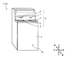
- the automatic teller machine 1 is configured around a box-shaped housing 2 and is configured to perform transactions relating to cash with a customer.
- the housing 2 is provided with a customer service portion 3 at a location where it is easy to insert a bill or operate with a touch panel while the customer is facing the front surface 2A side, that is, a location extending from the top of the front surface 2A to the upper surface.
- the customer service section 3 is configured to directly exchange cash, bankbooks, etc. with the customer, and is configured to receive information about transactions and accept operational instructions.
- the coin deposit / withdrawal port 4 and the banknote deposit / withdrawal port 5 A passbook insertion slot 6, a card insertion slot 7 and a display operation unit 8 are provided.
- the coin deposit / withdrawal port 4 and the bill deposit / withdrawal port 5 are portions where coins and bills BL to be deposited by the customer are respectively inserted, and coins and bills BL to be dispensed to the customer are respectively ejected. Moreover, the coin deposit / withdrawal port 4 and the banknote deposit / withdrawal port 5 are opened or closed by driving shutters provided respectively.
- banknote BL is comprised, for example with the rectangular paper.
- the bankbook insertion slot 6 is a part where a bankbook used in the transaction is inserted and the bankbook is discharged when the transaction is completed.
- a passbook processing section (not shown) for recording transaction contents and the like in a passbook is provided at the back of the passbook insertion slot 6.
- the card insertion slot 7 is a portion where various cards such as cash cards are inserted or ejected.
- a card processing section (not shown) for reading account numbers and the like magnetically recorded on various cards is provided at the back of the card insertion slot 7.
- the display operation unit 8 is integrated with an LCD (Liquid Crystal Display) that displays an operation screen at the time of transaction, and a touch panel for selecting a transaction type, inputting a personal identification number, transaction amount, and the like.
- LCD Liquid Crystal Display
- the housing 2 is configured by a door that can be opened and closed on a part of the side surface such as the front surface 2A side or the opposite side (that is, the back surface side). That is, the housing
- the housing 2 can easily perform work on each internal part by opening each door as necessary.
- the front side that is the front face 2A side of the automatic teller machine 1 and the rear side opposite to the front side
- the left side and the right side that are left and right as viewed from the customer facing the front face 2A side
- the upper side and the lower side are defined. I will explain.
- FIG. 2 is a side view of the automatic teller machine 1 shown in FIG. 1 as viewed from the left side, and mainly shows a part related to bill processing in the internal configuration of the automatic teller machine 1.
- a banknote processing unit 11 that performs various processes related to the banknote BL is provided on the upper side
- a banknote storage unit 12 that stores the banknote BL is provided on the lower side. It has been.
- a banknote deposit / withdrawal port 5 that is a part of the customer service unit 3
- a discrimination unit 14 that determines the denomination and authenticity of the banknote BL
- a temporary storage unit that temporarily holds the deposited banknote. 15 etc.
- the conveyance part 13 which makes the short side direction of the banknote BL the advancing direction, and conveys the said banknote BL along each predetermined
- prescribed conveyance path (it shows with a thick line in the figure) is provided. ing.
- the banknote storage unit 12 is provided with a banknote storage 17 that stores banknotes BL by denomination and a reject storage 18 that stores banknotes BL that are identified as not to be circulated due to damage or the like.
- the automatic teller machine 1 is configured so that the entire control is performed by the control unit 10. For example, when the customer performs a deposit transaction for depositing the bill BL, the control unit 10 receives a predetermined operation input via the display operation unit 8 (FIG. 1), and then opens the shutter of the bill deposit / withdrawal port 5 to open the bill. Insert BL.
- control unit 10 conveys the inserted bill BL to the discrimination unit 14 via the conveyance unit 13 for discrimination, and conveys the bill BL identified as a normal bill to the temporary storage unit 15 to temporarily hold it.
- the bill BL identified as not to be traded is conveyed to the bill deposit / withdrawal port 5 and returned to the customer.
- the banknote storage unit 12 conveys and stores the banknote BL identified as not damaged by the discrimination unit 14 to each banknote storage 17 corresponding to the denomination. Moreover, the banknote storage part 12 conveys the banknote BL identified as having been damaged by the discrimination part 14 to the rejection store
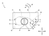
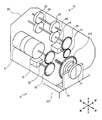
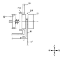
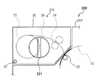
- the temporary storage portion 15 has a configuration in which each component is arranged in a frame 20 that forms an outer shell, and a hole formed in the left side surface of the frame 20.
- the operation knob 21 is exposed from 20H.
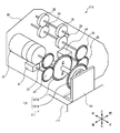
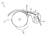
- the temporary storage unit 15 rotates the transport roller 24 that rotates in the arrow S1 direction and the transport roller 24. Accordingly, the bill BL is advanced backward along the transport path 26 by the driven roller 25 and the like rotating in the arrow T1 direction.
- the temporary storage unit 15 is configured to sequentially store the banknotes BL by rotating the cylindrical drum 27 in the direction of the arrow R1 and winding the banknotes BL together with a tape (not shown) around the outer periphery of the drums 27. Has been.
- the temporary storage part 15 receives the command which should discharge
- the banknote BL wound around the peripheral side surface of the said drum 27 is rotated by rotating the drum 27 to the arrow R2 direction. It is rewound together with the tape and delivered to the conveyance path 26.
- the temporary storage unit 15 advances the banknote BL forward along the transport path 26 by rotating the transport roller 24 in the arrow S2 direction and the driven roller 25 in the arrow T2 direction.
- the bill BL is delivered to the transport unit 13 of the bill processing unit 11.
- the temporary storage unit 15 rotates in the direction of the arrow U1 or the direction of the arrow U2 with respect to the banknote processing unit frame 11F (FIG. 2) of the banknote processing unit 11 around the rotation shaft 22 (FIG. 3) along the left-right direction. It is made to move.
- the temporary storage unit 15 is rotated about the rotation shaft 22, and similarly to the conventional temporary storage unit 215, the temporary storage unit 15 is mounted on the banknote processing unit frame 11 ⁇ / b> F (FIG. 16A) and the banknote processing unit. It is possible to transition between the detached state separated from the frame 11F (FIG. 16B).
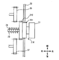
- a motor serving as a power source, a gear for transmitting a driving force, and the like are provided inside the temporary storage unit 15. Is provided.
- the motor 31 is configured to rotate based on the control of the control unit 10 (FIG. 2), and a gear 32 is attached to the output shaft thereof.
- the gear 32 meshes with a gear 33 attached to the rotation shaft of the drum 27.
- the temporary storage unit 15 is configured to transmit the rotational driving force to the drum 27 via the gear 32 and the gear 33 and rotate the drum 27.
- the motor 34 is configured to rotate based on the control of the control unit 10 (FIG. 2), and a gear 35 is attached to the output shaft thereof.
- the gear 35 meshes with a gear 36 attached to the rotation shaft of the transport roller 24.
- the temporary storage unit 15 transmits the rotational driving force to the transport roller 24 via the gear 35 and the gear 36, and rotates the transport roller 24 and the driven roller 25. Yes.
- the temporary storage unit 15 separates the drum driving system that transmits the driving force from the motor 31 to the drum 27 and the conveying driving system that transmits the driving force from the motor 34 to the conveying roller 24, which are independent of each other. It is made to be able to operate.
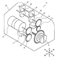
- the operation knob 21 has a shape in which a plurality of cylindrical members, gears, and the like are stacked in the left-right direction.
- the operation knob 21 is formed in a cylindrical shape having a central axis along the left-right direction as a whole, and a narrowed groove portion 21R is formed in the middle of the left and right.
- a gear portion 21C made of a spur gear is attached to the right end so as to share the central axis.
- a knob that can be easily grasped with a fingertip is formed on the left side surface of the cylindrical portion of the operation knob 21 by being punched into a predetermined shape.
- the operation knob 21 is attached so as to share a central axis with respect to the shaft 28, and can be freely rotated about the shaft 28 as a rotation center.
- the shaft 28 has an expansion / contraction mechanism (not shown), and the operation knob 21 can be moved in the left-right direction within a predetermined movement range by expanding / contracting the entire length thereof.
- a spring 29 made of a coil spring is inserted into the shaft 28 while being compressed from its natural length.
- the operation knob 21 is urged to the left by the urging force of the spring 29 in a state in which no external force is applied as in a normal operation in which normal transaction processing is performed in the automatic teller machine 1, As shown in FIG. 5A, the leftmost movement is achieved.
- the operation knob 21 causes most of the groove 21R to protrude to the left side of the frame 20, that is, to the outside of the frame 20. Further, the gear portion 21C does not mesh with any gear, so to speak, it is retracted and is in a floating state.
- the position of the operation knob 21 at this time is referred to as a retracted position.
- the operation knob 21 immerses most of the groove 21R including the groove 21R to the right side of the frame 20, that is, the inside of the frame 20. Further, the gear portion 21 ⁇ / b> C is in mesh with both the gears 32 and 35.
- the position of the operation knob 21 at this time is referred to as a gear position.
- the driving force can be transmitted to both the gears 32 and 35, and the drum 27, the transport roller 24, and the driven roller 25 can be transmitted. Can be rotated simultaneously.
- the drum 27 is conveyed.
- the roller 24 and the driven roller 25 can be simultaneously rotated in the directions indicated by the arrows R2, S2, and T2, respectively, so that the bills BL can be discharged from the delivery port 23.
- the temporary storage unit 15 holds the operation knob 21 in the retracted position during normal operation and causes the gear unit 21C to float, while the operation knob 21 is pushed into the meshing position during maintenance work or the like, the gear unit 21C is geared. It is configured to mesh with 32 and 35 and transmit the rotational driving force to the operation knob 21.
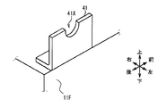
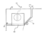
- the operation suppression plate 41 is configured such that a thick metal plate is bent in an inverted L shape when viewed from the rear side, and the left rear side in the banknote processing unit frame 11 ⁇ / b> F that forms the outer shell of the banknote processing unit 11. It is fixed by being screwed to the upper surface of.
- a notch 41 ⁇ / b> X whose upper part is rectangular and whose lower part is semicircular is cut out in a substantially U shape when viewed from the left and right direction. Is formed.
- the diameter of the semicircle forming the lower part of the notch 41X that is, the width in the front-rear direction of the upper part is smaller than the diameter of the columnar part of the operation knob 21 and slightly larger than the diameter of the groove 21R. Yes.
- the operation suppressing plate 41 is configured to engage with a groove portion 21 ⁇ / b> R formed on the operation knob 21 of the temporary storage portion 15 when the temporary storage portion 15 is in the mounted state. .
- the operation suppressing plate 41 has a notch 41X fitted into the groove 21R of the operation knob 21, and the bottom part of the notch 41X is the bottom part. Including it engages with the groove 21R.
- the operation suppression plate 41 suppresses the movement of the operation knob 21 in the right direction, and maintains the operation knob 21 in the retracted position, that is, the position where the gear portion 21C does not mesh with any of the gears 32 and 35.
- the operation knob 21 can move in the right direction, when an external force in the right direction is applied, the operation knob 21 moves to the meshing position, and the gear portion 21C is moved to the gears 32 and 35 as shown in FIG. 5B. And can be engaged with each other.
- the operation restraining plate 41 engages the notch portion 41X with the groove portion 21R of the operation knob 21 again when the temporary holding portion 15 is rotated in the direction of arrow U2 (FIG. 3) from the detached state and returned to the mounted state again.
- the movement of the operation knob 21 to the right is again suppressed and maintained at the retracted position.
- the operation suppressing plate 41 maintains the operation knob 21 in the retracted position by engaging the notch 41X with the groove 21R of the operation knob 21 only when the temporary holding portion 15 is in the mounted state. The engagement between the portion 21C and the gears 32 and 35 is suppressed.
- the banknote handling unit 11 of the automatic teller machine 1 is configured so that the temporary holding unit 15 can rotate with respect to the banknote handling unit frame 11F, and the operation knob 21 has a groove 21R. Formed.
- the temporary storage unit 15 allows the operation knob 21 to move between the retracted position and the meshing position, and does not mesh the gear part 21C of the operation knob 21 at the retracted position, while the gear 32 and 35.
- the banknote processing unit frame 11F was provided with an operation suppression plate 41 in which a U-shaped cutout 41X was formed.
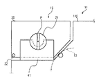
- the operation suppression plate 41 is configured to engage the notch 41 ⁇ / b> X with the groove 21 ⁇ / b> R of the operation knob 21 when the temporary storage unit 15 is in the mounted state and the delivery port 23 is close to the transport unit 13 of the banknote processing unit 11. (FIG. 7, FIG. 8A and FIG. 9).
- the bill processing unit frame 11 ⁇ / b> F is pulled out backward with respect to the housing 2 by an operation of a maintenance worker or the like.
- the temporary holding portion 15 is in the mounted state, and the groove portion 21R of the operation knob 21 is engaged with the notch portion 41X of the operation suppression plate 41.
- the temporary storage unit 15 can maintain the operation knob 21 in the retracted position (FIG. 5A) even if a rightward external force is applied to the operation knob 21 by a maintenance worker, and the gear unit 21C. Is not meshed with the gears 32 and 35.
- the temporary storage unit 15 does not transport the banknote BL even if the banknote BL is stored therein. .
- the bill BL is discharged from the delivery port 23 and is jammed in the transport path 26, the drum 27, the tape (not shown) or the like is damaged by the jammed bill BL, or It is possible to prevent the jammed bills BL from being damaged.
- the operation suppressing plate 41 is formed of a thick metal plate, even if a maintenance worker or the like applies an external force forcibly or carelessly, the operation suppressing plate 41 is less likely to be deformed or damaged. Can be kept in the retracted position.
- the operation suppressing plate 41 is formed so that the notch 41X is formed in a U shape deeper than the semicircular shape, so that the operation suppressing plate 41 extends to a portion above the rotation center of the operation knob 21 (shown as a point P in FIG. 8A).
- the groove portion 21R can be engaged within a range.
- the operation suppressing plate 41 can be engaged with the groove portion 21R on both the front and rear sides sandwiching the rotation center of the operation knob 21, so that this engagement is easy due to problems such as positional accuracy (so-called rattling or the like). The risk of being released can be reduced.
- the operation suppressing plate 41 is engaged with the groove portion 21R of the operation knob 21 even if the temporary storage portion 15 is slightly lifted upward with respect to the banknote processing portion frame 11F due to problems such as positional accuracy. The possibility that they can be combined can be increased.
- the operation suppression plate 41 has a relatively large area when viewed from the left and right direction, and is located on the left side of the frame 20 when the temporary storage portion 15 is in the mounted state, and forms the left side plate of the frame 20. It becomes almost parallel with a small gap from the part to be made (FIG. 8A, FIG. 9).
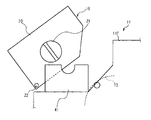
- the temporary holding portion 15 is released from the mounted state in the direction of the arrow U1 (FIG. 3), thereby releasing the engagement between the groove portion 21R of the operation knob 21 and the notch portion 41X of the operation suppressing plate 41. (FIG. 8B).
- the temporary holding unit 15 is simply operated by a maintenance worker or the like as in the prior art for the purpose of improving the efficiency of maintenance work or exposing a part of the delivery port 23 or the transport unit 13.
- the prohibition of the operation on 21 can be lifted.
- the temporary storage unit 15 allows the operation of the operation knob 21 only when the delivery port 23 is detached from the transport unit 13 of the banknote processing unit 11 and can discharge the banknote BL, and moves to the meshing position.
- the drum 21 and the conveying roller 24 can be rotated by engaging the portion 21 ⁇ / b> C with the gears 32 and 35.
- the operation knob 21 engages both the gears 32 and 35, which are originally driven independently of each other, with the gear portion 21C meshing, thereby simultaneously rotating the operation knob 21 to both the drum 27 and the transport roller 24 and the like. Can communicate.
- the temporary storage unit 15 can discharge the banknote BL wound around the drum 27 from the delivery port 23 only by operating the operation knob 21 with one hand, for example, for a maintenance worker, and the other hand.
- the banknote BL can be acquired.
- the banknote handling unit 11 of the automatic teller machine 1 engages the notch 41 ⁇ / b> X of the operation suppression plate 41 with the groove 21 ⁇ / b> R of the operation knob 21 when the temporary storage unit 15 is in the mounted state.
- the banknote processing unit 11 releases the engagement between the notch 41 ⁇ / b> X of the operation suppression plate 41 and the groove 21 ⁇ / b> R of the operation knob 21 when the temporary storage unit 15 is rotated and is in the detached state.
- the temporary storage unit 15 can move the operation knob 21 from the retracted position to the meshing position to mesh the gear unit 21C with the gears 32 and 35, and the drum 27 and the transport roller via the operation knob 21 can be engaged. Rotation operation with respect to 24 etc. can be enabled.
- the automatic teller machine 101 according to the second embodiment has a banknote processing unit 111 that replaces the banknote processing unit 11 as compared with the automatic teller machine 1 (FIGS. 1 and 2) according to the first embodiment. Although the points are different, the other parts are configured similarly.
- the banknote processing unit 111 is different from the banknote processing unit 11 according to the first embodiment in that the banknote processing unit 111 includes a temporary storage unit 115 and an operation suppression plate 141 instead of the temporary storage unit 15 and the operation suppression plate 41, The other parts are configured similarly.
- the temporary storage unit 115 is different from the temporary storage unit 15 (FIGS. 3 to 9) according to the first embodiment in that it has an operation knob 121 in place of the operation knob 21, but the other parts are not described. It is constituted similarly.
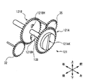
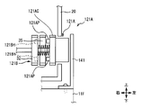
- the operation knob 121 includes a first gear 121A and a second gear 121B as shown in FIGS. 10 and 11A-B.
- the first gear 121A has a structure in which a thin disk-shaped member and a spur gear are overlapped so as to align the center axes of each other, and is attached to the shaft 128 so that the center axes are aligned.
- a knob 121AK is formed on the left surface of the disk-shaped portion of the first gear 121A by being punched into a predetermined shape.
- small quadrangular columnar projections 121AP projecting to the right are projected at two locations facing each other across the central axis. Yes.
- the second gear 121B is a spur gear as shown in FIG. 11B and is inserted through the shaft 128. Further, on the left side surface of the second gear 121B, holes 121BH each having a slightly larger square hole than the projection 121AP are formed at positions corresponding to the two projections 121AP on the first gear 121A.
- the second gear 121B is always in mesh with the gear 32 as shown in FIG. 12A.
- the gear 35 is located slightly to the left of the second gear 121B, and is not in mesh with the second gear 121B.
- the shaft 128 supports the second gear 121B so as not to move in the left-right direction and is rotatable, and allows the first gear 121A to move rightward until it abuts on the second gear 121B by extending and contracting a part thereof. It is designed to be rotatably supported.
- the spring 29 is inserted between the first gear 121A and the second gear 121B in the shaft 128 in a compressed state from the natural length.
- the first gear 121A of the operation knob 121 is urged to the left by the urging force of the spring 29 when no external force is applied, and is located on the leftmost side as shown in FIG. It will be in the state separated from the 2nd gear 121B.
- the position of the first gear 121A at this time is referred to as a separation position.
- the gear portion 121AC of the first gear 121A does not mesh with any of the gears, and is in a floating state.
- the second gear 121B meshes with the gear 32, but is separated from the first gear 121A.
- connection position the position of the first gear 121A at this time is referred to as a connection position.
- the position of the protrusion 121AP and the hole 121BH of the second gear 121B does not match only by moving the first gear 121A rightward, and there is a possibility that the two cannot be connected.
- the protrusion 121AP can be fitted into the hole 121BH by appropriately rotating the first gear 121A while pushing it in the right direction.
- the first gear 121A meshes the gear portion 121AC with the gear 35. Further, the second gear 121B always meshes with the gear 32. Furthermore, when a rotational force about the shaft 128 is applied to the first gear 121A, it can be transmitted to the second gear 121B via the protrusion 121AP.
- the operation knob 121 can transmit the driving force to both the gears 32 and 35 by rotating integrally with the second gear 121B.
- the drum 27, the transport roller 24, and the driven roller 25 can be rotated simultaneously.
- the first gear 121A of the operation knob 121 moves to the left by the restoring force of the spring 29 when the external force in the right direction is released at the connection position, and returns to the separation position (FIG. 12A).
- the temporary holding unit 115 holds the first gear 121A of the operation knob 121 in the separation position during normal operation and separates it from the gears 32 and 35, while the first gear 121A is pushed into the connection position during maintenance work or the like.
- the rotational driving force for the operation knob 121 can be transmitted to the gears 32 and 35.
- the operation suppression plate 141 has a shape in which the cutout portion 41 ⁇ / b> X is omitted from the operation suppression plate 41 in the first embodiment and is extended upward.
- the operation suppression plate 141 is configured to cover the first gear 121A of the operation knob 121 when the temporary holding portion 115 is in the mounted state.
- the operation suppressing plate 141 can prevent the maintenance worker or the like from operating the first gear 121A of the operation knob 121.
- the operation suppression plate 141 suppresses the rightward movement of the first gear 121A, the first gear 121A is in the separated position, that is, the first gear 121A is not connected to the second gear 121B, and the gear portion 121C is not connected. 35 is maintained in a state where it does not mesh with 35.
- the operation knob 121 can be operated by the maintenance worker or the like on the first gear 121A. Therefore, when an external force in the right direction is applied, the operation knob 121 moves to the coupling position, and as shown in FIG. It is possible to connect 121A to the second gear 121B and to engage the gear portion 121C with the gear 35.
- the operation suppressing plate 141 again covers the first gear 121A of the operation knob 121, and the first gear.
- the operation such as pushing or rotating the 121A is suppressed and maintained at the separation position.
- the operation suppression plate 141 covers the first gear 121A of the operation knob 121 only when the temporary storage portion 115 is in the mounted state, thereby maintaining the first gear 121A in the separated position and the second gear 121B. And the engagement between the gear portion 121C and the gear 35 is suppressed.
- the banknote handling unit 111 of the automatic teller machine 101 is configured so that the temporary holding unit 115 is rotatable with respect to the banknote handling unit frame 11F, and the operation knobs 121 are connected to each other.
- the first gear 121A and the second gear 121B2 are separated.
- the temporary storage unit 15 allows the first gear 121A of the operation knob 121 to be moved between the separation position and the connection position, and when the first gear 121A is in the connection position, the temporary storage unit 15 is connected to the second gear 121B2 and the gear.
- the portion 121C is meshed with the gear 35.
- the operation suppression plate 141 attached to the banknote processing unit frame 11F covers the first gear 121A of the operation knob 121 when the temporary storage unit 15 is in the mounted state (FIGS. 13, 14A, and 15).
- the temporary storage unit 115 can prevent the maintenance worker from touching the first gear 121A of the operation knob 121, and can maintain the first gear 121A in the separation position.
- the conveyance path 26 is clogged in an attempt to eject the bill BL from the delivery port 23, and the drum 27 or tape (see FIG. (Not shown) or the like, or damage to the jammed banknote BL can be prevented.
- the operation suppression plate 141 is formed of a thick metal plate, even if a maintenance worker or the like applies an external force forcibly or carelessly, the operation suppression plate 141 is less likely to be deformed or damaged.
- the first gear 121A can be kept in the separation position.
- the temporary storage unit 115 is exposed to the first gear 121A of the operation knob 121 from the operation suppression plate 141 by being turned from the attached state in the direction of the arrow U1 (FIG. 3) to be in the detached state (FIG. 3). 14B).
- the temporary storage unit 115 allows the operation of the operation knob 121 only when the delivery port 23 is separated from the transport unit 13 of the banknote processing unit 111 and the banknote BL can be discharged, and the first gear 121A is connected to the connection position.
- the gear portion 121C is engaged with the gear 35 to rotate the drum 27, the transport roller 24, and the like.
- the banknote processing unit 111 of the automatic teller machine 101 covers the first gear 121A of the operation knob 121 by the operation suppression plate 141 and holds it in the separation position when the temporary storage unit 115 is in the mounted state. Accordingly, the driving force is not transmitted to the gears 32 and 35, and the rotation operation with respect to the drum 27 and the transport roller 24 can be suppressed.
- the banknote processing unit 111 exposes the first gear 121 ⁇ / b> A of the operation knob 121 from the operation suppression plate 141 when the temporary storage unit 115 is rotated and is in the detached state.
- the temporary storage unit 115 can move the first gear 121A of the operation knob 121 from the separation position to the connection position to connect the second gear 121B2 and engage the gear unit 121C with the gear 35. It is possible to rotate the drum 27, the transport roller 24, and the like via the knob 121.
- the embodiment is not limited to this, and the shape of the notch may be various shapes such as a crank shape, a V shape, or a polygonal line shape.
- the operation knob 21 can be held in the retracted position by stably engaging the notch with the groove 21R of the operation knob 21 when the temporary storage portion 15 is in the mounted state.
- a rod-shaped member may be processed and formed into a Y shape or a V shape as viewed from the left and right directions.
- the operation is performed only when the temporary holding unit 15 is in the mounted state. It is sufficient that the knob 21 has a strength that can stably engage with the groove 21R of the knob 21 and is not easily deformed.
- the embodiment is not limited to this.
- the groove 21R is omitted from the operation knob 21, while the diameter of the semicircular portion in the notch 41X is slightly larger than the outer diameter of the shaft 28, and the notch 41X is made to operate the operation knob. You may make it engage in the connection location vicinity of 21 and the axis
- FIG. 1 the groove 21R is omitted from the operation knob 21, while the diameter of the semicircular portion in the notch 41X is slightly larger than the outer diameter of the shaft 28, and the notch 41X is made to operate the operation knob. You may make it engage in the connection location vicinity of 21 and the axis
- the embodiment is not limited to this, and the upper end portion of the operation suppression plate 41 is the rotation center of the operation knob 21 when the notch 41X of the operation suppression plate 41 is engaged with the groove 21R of the operation knob 21. You may make it stop below P.
- the embodiment is not limited to this.
- a part of the operation knob 121 may be exposed by the operation suppression plate 141. It suffices if the first gear 121A of the operation knob 121 is pushed in so that it cannot be connected to the second gear 121B.
- the operation knob 21 is configured integrally, and in the second embodiment, the operation knob 121 is configured to be separable into the first gear 121A and the second gear 121B. If you said.
- the embodiment is not limited to this.
- the operation knob 21 may be configured to be separable in the same manner as the second embodiment in the first embodiment, and the operation knob 121 in the second embodiment. May be configured integrally as in the first embodiment.
- the embodiment is not limited to this, and when the operation knob 21 is in the meshing position, it may mesh with only one of the gears 32 or 35, or mesh with three or more gears. Again. The same applies to the second embodiment.
- the embodiment is not limited to this.
- the numbers of the protrusions 121AP and the holes 121BH may be any number such as four or six. Further, the number of protrusions 121AP may be smaller than the number of holes 121BH.
- the embodiment is not limited to this.
- a rubber material having a large frictional force is attached to the outer periphery of the disk-shaped member, and the rotational force is transmitted by bringing the disk-shaped members into contact with each other.
- the rotational force applied via the operation knob can be transmitted to another member. The same applies to the second embodiment.
- the embodiment is not limited to this.
- the temporary storage unit 15 may be slid with respect to the banknote processing unit frame 11F via a predetermined slide rail to be changed to the mounted state or the detached state.
- the formation direction of the cutout portion 41X may correspond to the movement direction of the temporary storage portion 15. The same applies to the second embodiment.
- the embodiment is not limited to this.
- the present invention is applied to various parts in the automatic teller machine 1 such as a part of the transport unit 13, the discrimination unit 12, or the banknote storage 17.
- the portion is configured to be detachable with respect to the banknote processing unit frame 11F and the like, and has an operation knob for maintenance work. In this case, it is only necessary to suppress the operation of discharging the bill BL by the operation knob while enabling the operation by the operation knob in the detached state of the portion. The same applies to the second embodiment.
- the embodiment is not limited to this, and may be applied to various devices that hold a paper-like medium such as a gift certificate, a cash voucher, an admission ticket, or a medium such as a coin. The same applies to the second embodiment.
- the temporary storage part 15 as a temporary storage part
- the gearwheels 32 and 35 as a gearwheel
- the banknote process part frame 11F as a main-body part
- the operation knob 21 as an operation knob
- the embodiment is not limited to this, and the medium processing apparatus may be configured by a temporary storage unit, a gear, a main body unit, an operation knob, and an operation suppression unit having various other configurations.
- the present invention can also be used in an automatic teller machine that performs transactions related to cash including banknotes.
Landscapes
- Engineering & Computer Science (AREA)
- Mechanical Engineering (AREA)
- Physics & Mathematics (AREA)
- General Physics & Mathematics (AREA)
- Delivering By Means Of Belts And Rollers (AREA)
- Financial Or Insurance-Related Operations Such As Payment And Settlement (AREA)
- Casings For Electric Apparatus (AREA)
- Feeding And Guiding Record Carriers (AREA)
- Gear Processing (AREA)
- Cleaning In Electrography (AREA)
- Sheets, Magazines, And Separation Thereof (AREA)
Priority Applications (4)
| Application Number | Priority Date | Filing Date | Title |
|---|---|---|---|
| US14/129,509 US8967612B2 (en) | 2011-11-18 | 2012-09-25 | Medium processing device |
| RU2013157104/12A RU2569247C2 (ru) | 2011-11-18 | 2012-09-25 | Устройство обработки носителей |
| BR112013033457-6A BR112013033457B1 (pt) | 2011-11-18 | 2012-09-25 | Máquina de caixa automático de processamento de notas de banco |
| CN201280029821.7A CN103650008B (zh) | 2011-11-18 | 2012-09-25 | 介质处理装置 |
Applications Claiming Priority (2)
| Application Number | Priority Date | Filing Date | Title |
|---|---|---|---|
| JP2011-252916 | 2011-11-18 | ||
| JP2011252916A JP5783005B2 (ja) | 2011-11-18 | 2011-11-18 | 媒体処理装置 |
Publications (1)
| Publication Number | Publication Date |
|---|---|
| WO2013073291A1 true WO2013073291A1 (ja) | 2013-05-23 |
Family
ID=48429363
Family Applications (1)
| Application Number | Title | Priority Date | Filing Date |
|---|---|---|---|
| PCT/JP2012/074567 Ceased WO2013073291A1 (ja) | 2011-11-18 | 2012-09-25 | 媒体処理装置 |
Country Status (7)
| Country | Link |
|---|---|
| US (1) | US8967612B2 (enExample) |
| JP (1) | JP5783005B2 (enExample) |
| CN (2) | CN107093261B (enExample) |
| BR (1) | BR112013033457B1 (enExample) |
| MY (1) | MY175196A (enExample) |
| RU (1) | RU2569247C2 (enExample) |
| WO (1) | WO2013073291A1 (enExample) |
Cited By (2)
| Publication number | Priority date | Publication date | Assignee | Title |
|---|---|---|---|---|
| CN105474278A (zh) * | 2013-08-28 | 2016-04-06 | 富士通先端科技株式会社 | 纸页类交易装置 |
| WO2019225195A1 (ja) * | 2018-05-22 | 2019-11-28 | 沖電気工業株式会社 | 媒体処理装置及び媒体取引装置 |
Families Citing this family (11)
| Publication number | Priority date | Publication date | Assignee | Title |
|---|---|---|---|---|
| JP6229264B2 (ja) * | 2012-12-20 | 2017-11-15 | 沖電気工業株式会社 | 媒体処理装置及び媒体取引装置 |
| JP6264191B2 (ja) * | 2014-05-20 | 2018-01-24 | 沖電気工業株式会社 | 媒体収納装置及び媒体取引装置 |
| JP6623546B2 (ja) * | 2015-04-30 | 2019-12-25 | 沖電気工業株式会社 | 自動取引装置 |
| JP6737004B2 (ja) * | 2016-06-24 | 2020-08-05 | 沖電気工業株式会社 | 媒体処理装置及び媒体取引装置 |
| CN106097569B (zh) * | 2016-08-17 | 2022-09-27 | 上海古鳌电子科技股份有限公司 | 一种中传装置的连接机构 |
| KR101932190B1 (ko) * | 2016-09-21 | 2018-12-26 | 주식회사 에이텍에이피 | 매체 처리 장치 및 이를 구비한 금융기기 |
| WO2018061149A1 (ja) * | 2016-09-29 | 2018-04-05 | 富士通フロンテック株式会社 | 紙葉類収容装置及び紙葉類収容方法 |
| CN106652176A (zh) * | 2016-10-08 | 2017-05-10 | 深圳怡化电脑股份有限公司 | 一种暂存模块 |
| JP6863186B2 (ja) * | 2017-09-01 | 2021-04-21 | 沖電気工業株式会社 | 媒体処理装置及び自動取引装置 |
| JP7027994B2 (ja) | 2018-03-20 | 2022-03-02 | セイコーエプソン株式会社 | 画像読取装置 |
| JP6450042B1 (ja) * | 2018-03-29 | 2019-01-09 | 日本金銭機械株式会社 | 紙葉収納部、及び紙葉処理装置 |
Citations (1)
| Publication number | Priority date | Publication date | Assignee | Title |
|---|---|---|---|---|
| JP2011134222A (ja) * | 2009-12-25 | 2011-07-07 | Oki Electric Industry Co Ltd | 自動取引装置 |
Family Cites Families (12)
| Publication number | Priority date | Publication date | Assignee | Title |
|---|---|---|---|---|
| JP3207504B2 (ja) | 1992-03-26 | 2001-09-10 | 株式会社リコー | シート搬送装置 |
| CN2167411Y (zh) * | 1993-09-20 | 1994-06-01 | 恺昱企业有限公司 | 投币计数驱动显示装置 |
| JP2000062976A (ja) * | 1998-08-19 | 2000-02-29 | Ricoh Co Ltd | 給紙装置 |
| US6139011A (en) * | 1998-10-02 | 2000-10-31 | Hewlett-Packard Company | Jam clearance for printer path by manual operation |
| CA2299827C (en) * | 2000-03-02 | 2009-12-15 | Cashcode Company Inc. | Combination banknote validator and banknote dispenser |
| US6578845B2 (en) * | 2001-04-09 | 2003-06-17 | Mustek Systems Inc. | Automatic document feeding apparatus having separation mechanism |
| CA2502344A1 (en) * | 2005-03-24 | 2006-09-24 | Cashcode Company Inc. | Validator with recycling cassette and stacker |
| CN2821708Y (zh) * | 2005-08-29 | 2006-09-27 | 柳长庆 | 纸币清分机 |
| JP4368888B2 (ja) * | 2006-12-15 | 2009-11-18 | 日立オムロンターミナルソリューションズ株式会社 | 紙葉類収納庫および紙葉類取扱装置 |
| JP4867952B2 (ja) * | 2008-06-19 | 2012-02-01 | 沖電気工業株式会社 | 媒体収納繰出装置 |
| JP4811432B2 (ja) * | 2008-06-24 | 2011-11-09 | 沖電気工業株式会社 | 媒体収納繰出装置 |
| CN101673429B (zh) * | 2009-09-11 | 2012-01-25 | 广州广电运通金融电子股份有限公司 | 一种纸币传输通道装置 |
-
2011
- 2011-11-18 JP JP2011252916A patent/JP5783005B2/ja active Active
-
2012
- 2012-09-25 CN CN201710054306.9A patent/CN107093261B/zh active Active
- 2012-09-25 RU RU2013157104/12A patent/RU2569247C2/ru active
- 2012-09-25 CN CN201280029821.7A patent/CN103650008B/zh active Active
- 2012-09-25 WO PCT/JP2012/074567 patent/WO2013073291A1/ja not_active Ceased
- 2012-09-25 MY MYPI2014700092A patent/MY175196A/en unknown
- 2012-09-25 BR BR112013033457-6A patent/BR112013033457B1/pt active IP Right Grant
- 2012-09-25 US US14/129,509 patent/US8967612B2/en active Active
Patent Citations (1)
| Publication number | Priority date | Publication date | Assignee | Title |
|---|---|---|---|---|
| JP2011134222A (ja) * | 2009-12-25 | 2011-07-07 | Oki Electric Industry Co Ltd | 自動取引装置 |
Cited By (3)
| Publication number | Priority date | Publication date | Assignee | Title |
|---|---|---|---|---|
| CN105474278A (zh) * | 2013-08-28 | 2016-04-06 | 富士通先端科技株式会社 | 纸页类交易装置 |
| EP3040951A4 (en) * | 2013-08-28 | 2016-09-14 | Fujitsu Frontech Ltd | BANKNOTE TRANSACTION DEVICE |
| WO2019225195A1 (ja) * | 2018-05-22 | 2019-11-28 | 沖電気工業株式会社 | 媒体処理装置及び媒体取引装置 |
Also Published As
| Publication number | Publication date |
|---|---|
| RU2569247C2 (ru) | 2015-11-20 |
| CN107093261A (zh) | 2017-08-25 |
| RU2013157104A (ru) | 2015-06-27 |
| CN103650008A (zh) | 2014-03-19 |
| JP2013109500A (ja) | 2013-06-06 |
| JP5783005B2 (ja) | 2015-09-24 |
| BR112013033457A2 (pt) | 2017-01-24 |
| BR112013033457B1 (pt) | 2021-08-31 |
| US8967612B2 (en) | 2015-03-03 |
| US20140191466A1 (en) | 2014-07-10 |
| CN107093261B (zh) | 2019-07-19 |
| CN103650008B (zh) | 2017-02-22 |
| MY175196A (en) | 2020-06-15 |
Similar Documents
| Publication | Publication Date | Title |
|---|---|---|
| JP5783005B2 (ja) | 媒体処理装置 | |
| US8702088B2 (en) | Automatic transaction apparatus | |
| JP5724652B2 (ja) | 媒体処理装置 | |
| JP5704027B2 (ja) | 媒体処理装置及び媒体取引装置 | |
| JP5831321B2 (ja) | 媒体収納繰出装置及び媒体取引装置 | |
| US9611117B2 (en) | Medium processing device and medium transaction device | |
| JP2013025707A (ja) | 媒体処理装置及び媒体取引装置 | |
| CN104282075B (zh) | 纸币处理装置 | |
| JP5935512B2 (ja) | 媒体処理装置及び媒体取引装置 | |
| JP6565343B2 (ja) | 駆動力伝達装置及び媒体処理装置 | |
| JP2015087793A (ja) | 媒体移動装置及び媒体取引装置 | |
| WO2013140683A1 (ja) | 媒体処理装置 | |
| US10604364B2 (en) | Medium processing device and medium transaction device | |
| WO2019225195A1 (ja) | 媒体処理装置及び媒体取引装置 | |
| JP2019066962A (ja) | 媒体収納庫及び自動取引装置 | |
| JP2018032265A (ja) | 媒体処理装置及び媒体取引装置 | |
| WO2014080700A1 (ja) | 媒体集積装置及び媒体取引装置 |
Legal Events
| Date | Code | Title | Description |
|---|---|---|---|
| 121 | Ep: the epo has been informed by wipo that ep was designated in this application |
Ref document number: 12849017 Country of ref document: EP Kind code of ref document: A1 |
|
| ENP | Entry into the national phase |
Ref document number: 2013157104 Country of ref document: RU Kind code of ref document: A |
|
| WWE | Wipo information: entry into national phase |
Ref document number: 14129509 Country of ref document: US |
|
| REG | Reference to national code |
Ref country code: BR Ref legal event code: B01A Ref document number: 112013033457 Country of ref document: BR |
|
| NENP | Non-entry into the national phase |
Ref country code: DE |
|
| 122 | Ep: pct application non-entry in european phase |
Ref document number: 12849017 Country of ref document: EP Kind code of ref document: A1 |
|
| ENP | Entry into the national phase |
Ref document number: 112013033457 Country of ref document: BR Kind code of ref document: A2 Effective date: 20131226 |