WO2013073159A1 - 円筒状ガスケット及びその製造方法並びに該円筒状ガスケットを使用した差し込み型排気管継手 - Google Patents
円筒状ガスケット及びその製造方法並びに該円筒状ガスケットを使用した差し込み型排気管継手 Download PDFInfo
- Publication number
- WO2013073159A1 WO2013073159A1 PCT/JP2012/007254 JP2012007254W WO2013073159A1 WO 2013073159 A1 WO2013073159 A1 WO 2013073159A1 JP 2012007254 W JP2012007254 W JP 2012007254W WO 2013073159 A1 WO2013073159 A1 WO 2013073159A1
- Authority
- WO
- WIPO (PCT)
- Prior art keywords
- cylindrical
- heat
- resistant material
- powder
- gasket
- Prior art date
- Legal status (The legal status is an assumption and is not a legal conclusion. Google has not performed a legal analysis and makes no representation as to the accuracy of the status listed.)
- Ceased
Links
Images


Classifications
-
- F—MECHANICAL ENGINEERING; LIGHTING; HEATING; WEAPONS; BLASTING
- F16—ENGINEERING ELEMENTS AND UNITS; GENERAL MEASURES FOR PRODUCING AND MAINTAINING EFFECTIVE FUNCTIONING OF MACHINES OR INSTALLATIONS; THERMAL INSULATION IN GENERAL
- F16J—PISTONS; CYLINDERS; SEALINGS
- F16J15/00—Sealings
- F16J15/02—Sealings between relatively-stationary surfaces
- F16J15/06—Sealings between relatively-stationary surfaces with solid packing compressed between sealing surfaces
- F16J15/08—Sealings between relatively-stationary surfaces with solid packing compressed between sealing surfaces with exclusively metal packing
- F16J15/0806—Sealings between relatively-stationary surfaces with solid packing compressed between sealing surfaces with exclusively metal packing characterised by material or surface treatment
-
- F—MECHANICAL ENGINEERING; LIGHTING; HEATING; WEAPONS; BLASTING
- F01—MACHINES OR ENGINES IN GENERAL; ENGINE PLANTS IN GENERAL; STEAM ENGINES
- F01N—GAS-FLOW SILENCERS OR EXHAUST APPARATUS FOR MACHINES OR ENGINES IN GENERAL; GAS-FLOW SILENCERS OR EXHAUST APPARATUS FOR INTERNAL-COMBUSTION ENGINES
- F01N13/00—Exhaust or silencing apparatus characterised by constructional features
- F01N13/16—Selection of particular materials
-
- F—MECHANICAL ENGINEERING; LIGHTING; HEATING; WEAPONS; BLASTING
- F01—MACHINES OR ENGINES IN GENERAL; ENGINE PLANTS IN GENERAL; STEAM ENGINES
- F01N—GAS-FLOW SILENCERS OR EXHAUST APPARATUS FOR MACHINES OR ENGINES IN GENERAL; GAS-FLOW SILENCERS OR EXHAUST APPARATUS FOR INTERNAL-COMBUSTION ENGINES
- F01N13/00—Exhaust or silencing apparatus characterised by constructional features
- F01N13/18—Construction facilitating manufacture, assembly, or disassembly
- F01N13/1805—Fixing exhaust manifolds, exhaust pipes or pipe sections to each other, to engine or to vehicle body
- F01N13/1827—Sealings specially adapted for exhaust systems
-
- F—MECHANICAL ENGINEERING; LIGHTING; HEATING; WEAPONS; BLASTING
- F16—ENGINEERING ELEMENTS AND UNITS; GENERAL MEASURES FOR PRODUCING AND MAINTAINING EFFECTIVE FUNCTIONING OF MACHINES OR INSTALLATIONS; THERMAL INSULATION IN GENERAL
- F16J—PISTONS; CYLINDERS; SEALINGS
- F16J15/00—Sealings
- F16J15/02—Sealings between relatively-stationary surfaces
- F16J15/06—Sealings between relatively-stationary surfaces with solid packing compressed between sealing surfaces
- F16J15/08—Sealings between relatively-stationary surfaces with solid packing compressed between sealing surfaces with exclusively metal packing
- F16J15/0806—Sealings between relatively-stationary surfaces with solid packing compressed between sealing surfaces with exclusively metal packing characterised by material or surface treatment
- F16J15/0812—Sealings between relatively-stationary surfaces with solid packing compressed between sealing surfaces with exclusively metal packing characterised by material or surface treatment with a braided or knitted body
-
- F—MECHANICAL ENGINEERING; LIGHTING; HEATING; WEAPONS; BLASTING
- F16—ENGINEERING ELEMENTS AND UNITS; GENERAL MEASURES FOR PRODUCING AND MAINTAINING EFFECTIVE FUNCTIONING OF MACHINES OR INSTALLATIONS; THERMAL INSULATION IN GENERAL
- F16J—PISTONS; CYLINDERS; SEALINGS
- F16J15/00—Sealings
- F16J15/02—Sealings between relatively-stationary surfaces
- F16J15/06—Sealings between relatively-stationary surfaces with solid packing compressed between sealing surfaces
- F16J15/10—Sealings between relatively-stationary surfaces with solid packing compressed between sealing surfaces with non-metallic packing
- F16J15/12—Sealings between relatively-stationary surfaces with solid packing compressed between sealing surfaces with non-metallic packing with metal reinforcement or covering
- F16J15/121—Sealings between relatively-stationary surfaces with solid packing compressed between sealing surfaces with non-metallic packing with metal reinforcement or covering with metal reinforcement
- F16J15/126—Sealings between relatively-stationary surfaces with solid packing compressed between sealing surfaces with non-metallic packing with metal reinforcement or covering with metal reinforcement consisting of additions, e.g. metallic fibres, metallic powders, randomly dispersed in the packing
-
- F—MECHANICAL ENGINEERING; LIGHTING; HEATING; WEAPONS; BLASTING
- F16—ENGINEERING ELEMENTS AND UNITS; GENERAL MEASURES FOR PRODUCING AND MAINTAINING EFFECTIVE FUNCTIONING OF MACHINES OR INSTALLATIONS; THERMAL INSULATION IN GENERAL
- F16L—PIPES; JOINTS OR FITTINGS FOR PIPES; SUPPORTS FOR PIPES, CABLES OR PROTECTIVE TUBING; MEANS FOR THERMAL INSULATION IN GENERAL
- F16L21/00—Joints with sleeve or socket
- F16L21/06—Joints with sleeve or socket with a divided sleeve or ring clamping around the pipe ends
- F16L21/065—Joints with sleeve or socket with a divided sleeve or ring clamping around the pipe ends tightened by tangentially-arranged threaded pins
-
- F—MECHANICAL ENGINEERING; LIGHTING; HEATING; WEAPONS; BLASTING
- F16—ENGINEERING ELEMENTS AND UNITS; GENERAL MEASURES FOR PRODUCING AND MAINTAINING EFFECTIVE FUNCTIONING OF MACHINES OR INSTALLATIONS; THERMAL INSULATION IN GENERAL
- F16L—PIPES; JOINTS OR FITTINGS FOR PIPES; SUPPORTS FOR PIPES, CABLES OR PROTECTIVE TUBING; MEANS FOR THERMAL INSULATION IN GENERAL
- F16L23/00—Flanged joints
- F16L23/16—Flanged joints characterised by the sealing means
-
- Y—GENERAL TAGGING OF NEW TECHNOLOGICAL DEVELOPMENTS; GENERAL TAGGING OF CROSS-SECTIONAL TECHNOLOGIES SPANNING OVER SEVERAL SECTIONS OF THE IPC; TECHNICAL SUBJECTS COVERED BY FORMER USPC CROSS-REFERENCE ART COLLECTIONS [XRACs] AND DIGESTS
- Y10—TECHNICAL SUBJECTS COVERED BY FORMER USPC
- Y10T—TECHNICAL SUBJECTS COVERED BY FORMER US CLASSIFICATION
- Y10T29/00—Metal working
- Y10T29/49—Method of mechanical manufacture
- Y10T29/49398—Muffler, manifold or exhaust pipe making
Definitions
- the present invention relates to a cylindrical gasket suitable for use in a plug-in type exhaust pipe joint used in vehicles such as ATV (All Terrain Vehicle), snowmobiles, two-wheeled vehicles, etc., a manufacturing method thereof, and the cylindrical gasket
- ATV All Terrain Vehicle
- snowmobiles snowmobiles
- two-wheeled vehicles etc.
- a manufacturing method thereof and the cylindrical gasket
- the present invention relates to a plug-in type exhaust pipe joint.
- the plug-in type exhaust pipe joint has an inner pipe and an outer pipe having an inner diameter substantially the same as the outer diameter of the inner pipe, and the outer pipe has an enlarged diameter portion at the end of the pipe.
- the inner tube has a tube end portion that passes through the diameter-enlarged portion of the outer tube and is fitted to the tube end portion of the outer tube at one end, and the tube end portion of the inner tube and the diameter-enlarged portion of the outer tube A gasket is fitted in an annular gap between the inner and outer pipes, and a gap between the inner and outer pipes is sealed by a fastening band disposed on the outer peripheral surface of the outer pipe (Patent Document 1). Patent Document 2 and Patent Document 3).
- an expanded graphite sheet is cut into a strip having a certain width and length, and on the strip, the length of the expanded graphite sheet is approximately the same.
- a metal mesh cut into equal lengths is placed on top of each other and wound around a cylindrical core bar with the wire mesh inside to produce a cylindrical body.
- the cylindrical body is placed in a mold and its axial direction.
- a gasket in which a metal mesh or expanded graphite is exposed on the inner peripheral surface, and both end surfaces and the outer peripheral surface thereof are covered with expanded graphite (see Patent Document 1 and Patent Document 3).
- a gasket main body surrounded by a metal mesh material is provided on the entire surface of the expanded graphite sheet.
- the gasket main body is annularly bent and compressed by a press to integrally fix the expanded graphite and the mesh material.
- An annular gasket has also been proposed (see Patent Document 4).
- the gasket made of expanded graphite and wire mesh disposed between the inner pipe of the exhaust pipe joint and the enlarged diameter part of the outer pipe expands in volume by the heat of the exhaust gas flowing in the inner pipe and is flexible and flexible. Therefore, it can adapt well to the gap between the inner tube and the outer tube, and can be adapted to improve the sealing performance between the inner tube and the outer tube (see Patent Document 1). ).
- JP-A 61-244815 Japanese Utility Model Publication No. 6-36273 JP-A-6-146875 Japanese Utility Model Publication No. 5-47620
- the exhaust pipe has become larger as a countermeasure against noise, and a catalyst device has been attached to the exhaust pipe as a countermeasure against exhaust gas, and an excessive load has been added to the plug-in type exhaust pipe joint. ing.
- vibration load, bending torque, and twisting between the inner and outer pipes are repeatedly generated at the joint part.
- the gasket With the above-mentioned vibration load, bending torque and twisting that occur repeatedly, the gasket has the flexibility required to exert its sealing property and the rigidity to receive the tightening force without causing settling when tightening with the fastening band. Is required.
- the above-described conventional gaskets are specialized in either flexibility or rigidity, and it is difficult to achieve both performances. As a result, gaskets specialized in rigidity.
- the sealing performance of the gap between the inner and outer pipes is lowered due to loosening of the fastening band caused by the gasket settling or the like. May cause problems.
- the present invention has been made in view of the above-mentioned points, and an object of the present invention is to provide a cylindrical gasket suitable for use in a plug-in type exhaust pipe joint, which has both sealing performance and rigidity, a manufacturing method thereof, and the It is an object of the present invention to provide a plug-in type exhaust pipe joint using a cylindrical gasket.
- the cylindrical gasket used for the plug-in type exhaust pipe joint of the present invention is a heat-resisting material comprising a compressed wire mesh, and a graphite and an inorganic binder that are filled and compressed into the mesh of the wire mesh of the reinforcing material. Material and pores distributed and distributed in the reinforcing material and the heat-resistant material, the reinforcing material and the heat-resistant material are intertwined with each other to have structural integrity, and the entire cylindrical gasket
- the reinforcing material occupies a volume of 32 to 60%
- the heat-resistant material occupies a volume of 5 to 58%
- the pores occupy a volume of 10 to 35%.
- the contents of the reinforcing material and the heat-resistant material are 32 to 60% and 5 to 58% by volume, respectively, so that the tightening force by the fastening band and the load due to vibration are mainly made of a wire mesh.
- the mesh of the reinforcing material is filled with a heat-resistant material and the pore content is 10 to 35% by volume.
- the cylindrical gasket of the present invention by being incorporated in a plug-in type exhaust pipe joint, the inorganic binder in the heat-resistant material is heated by the action of the heat of the high-temperature exhaust gas flowing in the exhaust pipe. Curing bondability is exhibited by condensation due to dehydration and crystal transition due to high temperature heating, and as a result, the rigidity of the cylindrical gasket is further increased.
- the graphite is preferably selected from at least one selected from natural graphite, artificial graphite, and expanded graphite made of scale-like graphite, earth-like graphite, scale-like graphite, and massive graphite.
- the inorganic binder includes aluminum dihydrogen phosphate (primary aluminum phosphate) [Al (H 2 PO 4 ) 3 ], aluminum hydrogen phosphate (second aluminum phosphate) [Al 2 (HPO 4 ) 3 ], magnesium dihydrogen phosphate (primary magnesium phosphate) [Mg (H 2 PO 4 ) 2 ], magnesium hydrogen phosphate (secondary magnesium phosphate) (MgHPO 4 ), dihydrogen phosphate At least one of calcium (primary calcium phosphate) [Ca (H 2 PO 4 ) 2 ], calcium hydrogen phosphate (dibasic calcium phosphate) (CaHPO 4 ) and phosphoric acid (H 3 PO 4 ) is selected and used. Good.
- inorganic binders join the graphite powder together with the heat-resistant powder reinforcing material to the wire mesh, and the inorganic binder is incorporated into the graphite to condense by heat dehydration and crystal transition by high-temperature heating. Etc., exhibiting the effect of increasing the rigidity of the cylindrical gasket by exhibiting the curing bondability.
- the mass ratio of graphite and inorganic binder contained in the heat-resistant material is preferably 1: 0.1 to 1, more preferably 1: 0.15 to 0.75.
- the reinforcing material is densely contained in the radial direction from the cylindrical inner peripheral surface to the cylindrical outer peripheral surface.
- the reinforcing material is densely contained, the tightening force by the fastening band and the load by the reinforcing material due to vibration can be more preferably performed, and the occurrence of settling can be further reduced.
- a reinforcing material composed of a compressed wire mesh, a heat resistant material filled with the compressed wire mesh and containing graphite powder and an inorganic binder, and dispersed in the reinforcing material and the heat resistant material.
- the reinforcing material and the heat-resistant material are intertwined with each other to have structural integrity.
- the reinforcing material has a volume of 32 to 60% of the total volume.
- the heat-resistant material occupies a volume of 5 to 58%, the pores occupy a volume of 10 to 35%, and the manufacturing method of the cylindrical gasket of the present invention used for the plug-in type exhaust pipe joint is (1 )
- metal Cylinder obtained by knitting fine wires A step of producing a belt-like wire mesh by passing the wire mesh between a pair of rollers in the radial direction; and (3) supplying the heat-resistant material powder to both sides of the belt-like wire mesh and rolling the heat-resistant material powder between rolls.
- a step of producing the composite band-shaped material formed After filling the wire mesh with heat-resistant material powder, dry the heat-resistant material powder filled in the belt-like wire mesh to remove moisture in the heat-resistant material powder, and fill and hold the heat-resistant material powder in the wire-like wire mesh
- a step of producing the composite band-shaped material formed (4) a step of winding the composite band-shaped material in a cylindrical shape at least twice to produce a cylindrical base material, and (5) a cylindrical base material of the cylindrical base material. And a step of compressing and molding the cylindrical base material in the axial direction in the mold.
- the volume content of the reinforcing material, the heat-resistant material and the pores with respect to the entire cylindrical gasket is 32 to 60% for the reinforcing material, 5 to 58% for the heat-resistant material, and 10 to 35 for the pores. %, It is possible to obtain a cylindrical gasket having both sealing performance and rigidity.
- the graphite powder is selected from at least one of expanded graphite powder, natural graphite powder and artificial graphite powder
- the expanded graphite powder is a powder obtained by cutting and pulverizing an expanded graphite sheet.
- the inorganic binder is at least one of aluminum dihydrogen phosphate, aluminum hydrogen phosphate, magnesium dihydrogen phosphate, magnesium hydrogen phosphate, calcium dihydrogen phosphate, calcium hydrogen phosphate and phosphoric acid.
- the mass ratio of the graphite powder, the inorganic binder, and distilled water contained in the heat-resistant material powder is 1: 0.1 to 1: 0.1 to 1.
- the plug-in type exhaust pipe joint of the present invention includes a pipe end, a diameter-enlarging cylindrical part provided with an enlarged diameter at the pipe end via an annular shoulder, and one end in the axial direction of the diameter-enlarging cylindrical part.
- An opening end provided on the outer peripheral surface of the opening end, a flange portion extending radially outward from the opening end portion, the enlarged cylindrical portion and the flange portion along the axial direction from the annular end surface of the opening end And it passes through the inside of the diameter-enlarged cylindrical part of the outer pipe provided with a plurality of slits provided equally in the circumferential direction, and is fitted to the pipe end of the outer pipe at one end.
- An inner pipe provided with a flange erected on the outer peripheral surface of the other end of the pipe end, a cylindrical outer surface of the pipe end of the inner pipe, and a cylindrical inner surface of the expanded cylindrical part of the outer pipe And the cylindrical inner surface of the expanded cylindrical portion of the outer tube by fastening the cylindrical gasket fitted in the annular gap between A fastening band disposed on the cylindrical outer surface of the enlarged-diameter cylindrical portion of the outer tube so that the cylindrical inner peripheral surface of the cylindrical gasket is pressed against the cylindrical outer surface of the inner tube through the pressing.
- the cylindrical gasket is arranged in such a manner that an annular end surface of one end portion in the axial direction is in contact with the flange of the inner tube in the annular gap.
- the cylindrical gasket fitted in the annular gap between the outer peripheral surface of the pipe end portion of the inner tube and the cylindrical inner surface of the expanded cylindrical portion of the outer tube is a reinforcing material.
- the volume content is 32 to 60% of the reinforcing material, 5 to 58% of the heat resistant material, and 10 to 35% of the pores, respectively.
- the sealing performance of the gap between the inner pipe and the outer pipe is improved, and the leakage of exhaust gas from the gap is prevented as much as possible.
- the cylindrical gasket used in this plug-in type exhaust pipe joint is the action of high-temperature exhaust gas flowing in the exhaust pipe. Since the curing bondability is expressed by the transfer or the like and the rigidity is increased, there is no problem such as sag and the rigidity can be maintained for a long period of time.
- the cylindrical gasket having both sealing performance and rigidity And a method of manufacturing the same, and a plug having a cylindrical gasket that can improve the sealing performance of the gap between the inner pipe and the outer pipe and can prevent leakage of exhaust gas from the gap as much as possible.
- Each type of exhaust pipe joint can be provided.
- FIG. 1 is a perspective explanatory view of a cylindrical gasket manufactured in an example of an embodiment of the present invention.
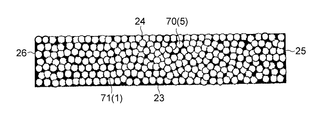
- 2 is a schematic explanatory view taken along the line II-II in FIG.
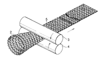
- FIG. 3 is a perspective explanatory view of a reinforcing material forming method in the manufacturing process of the cylindrical gasket of the present invention.
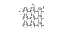
- FIG. 4 is an explanatory plan view of a mesh of reinforcing material.
- FIG. 5 is a cross-sectional explanatory view of a method for forming a composite strip in the manufacturing process of the cylindrical gasket of the present invention.
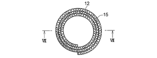
- FIG. 6 is a plan view of the cylindrical base material in the manufacturing process of the cylindrical gasket of the present invention.
- FIG. 7 is a cross-sectional explanatory view taken along the line VII-VII of the cylindrical base material shown in FIG.
- FIG. 8 is an explanatory cross-sectional view showing a state in which a cylindrical base material is inserted into a mold in the manufacturing process of the cylindrical gasket of the present invention.
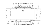
- FIG. 9 is a longitudinal cross-sectional explanatory view of a plug-in type exhaust pipe joint incorporating an example of the cylindrical gasket of the present invention.
- FIG. 10 is a perspective explanatory view of the inner pipe of the plug-in type exhaust pipe joint.
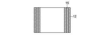
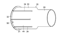
- FIG. 11 is an explanatory perspective view of the outer pipe of the plug-in type exhaust pipe joint.
- FIG. 12 is a perspective explanatory view of a fastening band of the plug-in type exhaust pipe joint.
- the graphite powder used for the heat-resistant material is selected from at least one of natural graphite powder, artificial graphite powder and expanded graphite powder made of at least one of scaly graphite, earthy graphite, scaly graphite and massive graphite. .
- the expanded graphite powder is obtained by immersing raw graphite (natural graphite) powder in a solution containing an acidic substance and an oxidizing agent to form a graphite intercalation compound, which is heated and expanded in the C-axis direction of the graphite crystal. This refers to the graphite powder.
- the above-mentioned acid-treated graphite powder is heated (expanded) at a temperature of 950 to 1200 ° C. for 1 to 10 seconds to generate decomposition gas, and expanded between the graphite layers by the gas pressure (expansion magnification) 240 to 300 times).
- the expanded graphite powder produced in this way can be used as a heat-resistant material in the present invention, but the expanded graphite powder has a very low bulk density of 0.05 g / cm 2 and is difficult to handle. Therefore, in the present invention, the expanded graphite powder is supplied to a twin roller device adjusted to a desired roll gap and roll-formed to produce an expanded graphite sheet having a desired thickness.
- the expanded graphite pulverized powder obtained by cutting and pulverizing is preferably used as the expanded graphite powder.
- Inorganic binder As an inorganic binder that holds the graphite powder as a reinforcing material at the same time as the joining of the graphite powders and the inorganic binder, aluminum dihydrogen phosphate, aluminum hydrogen phosphate, magnesium dihydrogen phosphate, magnesium hydrogen phosphate, At least one of calcium dihydrogen phosphate, calcium hydrogen phosphate and phosphoric acid is selected and used.
- ⁇ Reinforcing material> austenitic SUS304, SUS310S, SUS316, ferritic SUS430, etc., stainless steel wire, iron wire (JISG3532) or galvanized steel wire (JISG3547) or copper-nickel alloy as copper Braided wire mesh formed by braiding (white copper) wire, copper-nickel-zinc alloy (white) wire, brass wire, beryllium copper wire using one or more wires, flat braid
- a wire mesh, particularly a cylindrical wire mesh made of a cylindrical braided wire mesh is preferably used.
- the wire mesh for reinforcing material formed of the fine metal wire of the wire diameter has a mesh width ( A braided wire mesh (see FIG. 4) having a length of about 1.5 to 6 mm and a width of about 1.0 to 5 mm is preferably used.
- graphite powder At least one of natural graphite, artificial graphite, expanded graphite and expanded graphite powder obtained by pulverizing expanded graphite sheet, natural graphite powder and artificial graphite powder is prepared.
- Blends inorganic binder selected from at least one of aluminum hydride, magnesium dihydrogen phosphate, magnesium hydrogen phosphate, calcium dihydrogen phosphate, calcium hydrogen phosphate, and phosphoric acid in a predetermined ratio are kneaded to prepare heat-resistant material powder 1 having wettability composed of graphite powder, inorganic binder and distilled water.
- the mass ratio of the graphite powder, the inorganic binder, and distilled water contained in the heat-resistant material powder 1 having wettability is preferably 1: 0.1 to 1: 0.1 to 1.
- the mesh width obtained by continuously knitting a fine metal wire having a wire diameter of 0.05 to 0.50 mm with a knitting machine has a vertical width of 0.25 to 6 mm, and a horizontal width of 1.
- a cylindrical wire mesh 2 made of a cylindrical braided wire mesh of about 5 to 5 mm is prepared, and the cylindrical wire mesh 2 is passed through a pair of rollers 3 and 4 and compressed in the radial direction to form a belt having a desired width.
- a wire mesh 5 is produced.
- the belt-like wire mesh 5 is inserted into the hopper 7 in the rolling device 6, and the insertion end of the belt-like wire mesh 5 is passed between the pair of rollers 8 and 9.
- the heat-resistant material powder 1 having wettability is supplied from the conveyors 10 and 11.
- the heat-resistant material powder 1 supplied to the hopper 7 is supplied to both surfaces of the belt-like wire mesh 5 between the rollers 8 and 9, and the heat-resistant material powder 1 is rolled between the rollers 8 and 9 to form the heat-resistant material powder in the mesh of the belt-like wire mesh 5.
- reference numeral 13 denotes a load cell arranged on one roller 8 side
- 14 denotes a fluid cylinder arranged on the other roller 9 side.
- the composite strip material 12a After producing the composite strip material 12a wound into a roll cut to a desired length, the composite strip material 12a is dried in a drying furnace, and moisture is removed from the heat-resistant powder 1 in the composite strip material 12a by evaporation. After that, the composite strip material 12a is cut into a desired length to produce a composite strip material 12 in which the heat-resistant powder 1 is filled and held in the mesh of the strip metal mesh 5, and this composite strip material 12 is shown in FIGS. As shown in FIG. 7, the cylindrical base material 15 is produced by winding in a spiral shape at least two times around the core metal (not shown), three times in the embodiment.
- a mold 20 as shown in FIG. 8 in which a hollow cylindrical portion 19 is formed by inserting a stepped core 18 into the through hole 16 of the cavity 17 having the through hole 16 therein is prepared.
- the cylindrical base material 15 is inserted into the 20 stepped cores 18.
- the cylindrical base material 15 inserted into the hollow cylindrical portion 19 of the mold 20 is compression-molded with a punch 21 in the core axial direction at a pressure of 98 to 294 N / mm 2 (1 to 3 tons / cm 2 ), and FIG.
- a cylindrical gasket 27 having a cylindrical inner peripheral surface 23 that defines the through-hole 22, a cylindrical outer peripheral surface 24, and annular end surfaces 25 and 26 is produced.
- the cylindrical gasket 27 produced by compression molding of the cylindrical base material 15 is composed of the compressed band-shaped metal mesh 5 and is filled with the compressed reinforcing material 70 and the mesh of the band-shaped metal mesh 5 of the reinforcing material 70. It has a heat-resistant material 71 containing compressed graphite and an inorganic binder, and a reinforcing material 70 and pores distributed in the heat-resistant material 71. The reinforcing material 70 and the heat-resistant material 71 are intertwined with each other.
- the inner peripheral surface 23 and the outer peripheral surface 24 and the end surfaces 25 and 26 of the cylindrical gasket 27 are smooth surfaces in which the reinforcing material 70 and the heat-resistant material 71 are mixed.
- the volume contents of the reinforcing material 70, the heat-resistant material 71, and the pores are 32 to 60%, respectively. 5-5 Is the percent and 10 to 35%.
- the amount of the pore content contained in the cylindrical gasket 27 is related to the sealing performance of the cylindrical gasket 27.
- the pore content is less than 10% by volume, the rigidity of the cylindrical gasket 27 itself is low.
- the cylindrical gasket 27 is difficult to insert into the inner peripheral surface of the exhaust pipe, the initial conformability with the inner peripheral surface of the exhaust pipe is poor, and as a result, the sealing performance may be lowered.
- the content ratio exceeds 35% by volume, many continuous pores appear inside the cylindrical gasket 27, which may reduce the sealing performance and the rigidity of the cylindrical gasket 27. Therefore, the content ratio of the pores contained in the cylindrical gasket 27 is preferably 10 to 35%, more preferably 15 to 30% in volume ratio.
- the cylindrical gasket 27 is used by being incorporated in a plug-in type exhaust pipe joint shown in FIG.
- the plug-in type exhaust pipe joint shown in FIG. 9 includes a pipe end portion 28, an enlarged diameter cylindrical portion 30 formed by expanding the diameter of the pipe end portion 28 via a tapered annular shoulder portion 29, An opening end 31 formed at one end in the axial direction, a flange 32 formed on the outer peripheral surface of the opening end 31 and extending radially outward, and an opening end at the enlarged-diameter cylindrical portion 30 and the flange 32 An outer tube 35 (see FIGS.
- the diameter of the outer tube 35 is increased through the inner peripheral surface 52 of the cylindrical body 46 by tightening the fastener 51 such as a bolt inserted into the through-holes 49 and 50 of the ear portions 47 and 48.
- the cylindrical inner surface 42 of the cylindrical portion 30 is pressed against the cylindrical outer peripheral surface 24 of the cylindrical gasket 27, and the cylindrical inner peripheral surface 23 of the cylindrical gasket 27 is pressed against the cylindrical inner surface 23 of the cylindrical tube 27 through this pressing. Press against the outer surface 41
- the cylindrical gasket 27 is disposed in the annular gap 43 such that one end face 26 in the axial direction is in contact with the flange 39 of the inner tube 40.
- An annular gap 43 between the outer pipe 35 and the outer pipe 35 is sealed to prevent leakage of exhaust gas from the annular gap 43.
- one end 53 of the end portions 53 and 54 in the axial direction of the fastening band 45 is provided with a hook portion 55 projecting radially inward
- the hook portion 55 having a cross section similar to the notch portion 56 formed in the flange portion 32 of the enlarged diameter cylindrical portion 30 of the outer tube 35 has a fastening band 45 of the enlarged diameter cylindrical portion 30 of the outer tube 35.
- the cylindrical gasket 27 used by being incorporated in a plug-in type exhaust pipe joint condensation by heat dehydration is performed on the inorganic binder in the heat-resistant material by the action of the heat of the high-temperature exhaust gas flowing in the inner pipe 40 of the exhaust pipe.
- the hardened bonding property is manifested by the crystal transition caused by high temperature heating and the rigidity of the heat-resistant material is increased, the cylindrical gasket 27 is not damaged, and the rigidity of the cylindrical gasket 27 is increased over a long period of time. Can be maintained.
- the cylindrical gasket 27 with increased rigidity does not cause any problems such as settling due to a large tightening force by the fastening band 45, so that the hook portion 55 and the notch portion 56 are fastened.
- the band 45 and the flange portion 32 are not necessarily provided.
- Example 1 As the graphite powder, an expanded graphite powder produced by cutting and pulverizing an expanded graphite sheet having a density of 1.2 Mg / m 3 and a thickness of 0.4 mm was used.
- aluminum dihydrogen phosphate primary aluminum phosphate [Al (H 2 PO 4 ) 3 ] was used.
- Expanded graphite powder, aluminum dihydrogen phosphate, and distilled water were blended at a mass ratio of 1: 0.25: 0.75, and these were kneaded to produce a heat-resistant material powder having wettability.
- a cylindrical braided wire net having a mesh width of about 2.0 mm and a width of about 1.5 mm is prepared using seven austenitic stainless steel wires (SUS304) having a wire diameter of 0.15 mm as thin metal wires.
- SUS304 austenitic stainless steel wires
- a band metal mesh for reinforcing material was passed between a pair of rollers.
- the produced composite strip material is dried in a drying furnace to evaporate and dissipate moisture contained in the heat-resistant material powder, and then the dried composite strip material is cut to a length of about 63 mm in width and about 175 mm in length.
- Composite strip material (mass of composite strip material: 32.7 g, mass of strip metal mesh in composite strip material: 27.2 g, mass of aluminum dihydrogen phosphate: 1.1 g, and mass of expanded graphite powder: 4.4 g ) was produced.
- a cylindrical base material was produced by winding a composite strip material in a spiral shape on the outer peripheral surface of a cylindrical cored bar twice.
- a cylindrical base material was inserted into a stepped core of a mold shown in FIG. 8 in which a hollow cylindrical portion was formed by fitting a stepped core into the through hole of a cavity having a through hole on the inner surface.
- the cylindrical base material arranged in the hollow cylindrical part of the mold is compression-molded with a pressure of 196 N / mm 2 (2 ton / cm 2 ) in the core axial direction, and the cylindrical inner peripheral surface defining the through hole and the cylindrical shape
- a cylindrical gasket having an inner diameter of 22.1 mm, an outer diameter of 29.4 mm, and a length of 25.0 mm was prepared.
- the contents of the reinforcing material, the heat-resistant material, and the pores were 46.5%, 37.0%, and 16.5% in volume ratio, respectively.
- Example 2 As the graphite powder, the same expanded graphite powder as in Example 1 was used, and as the inorganic binder, calcium dihydrogen phosphate (primary calcium phosphate) [Ca (H 2 PO 4 ) 2 ] was used. Calcium dihydrogen phosphate and distilled water were blended at a mass ratio of 1: 0.25: 0.75, and kneaded to prepare a heat-resistant material powder having wettability.
- calcium dihydrogen phosphate primary calcium phosphate
- distilled water were blended at a mass ratio of 1: 0.25: 0.75, and kneaded to prepare a heat-resistant material powder having wettability.
- strip metal mesh As the strip metal mesh, the same strip metal mesh as in Example 1 was used.
- the composite strip material is dried in a drying furnace to evaporate and dissipate the moisture contained in the heat-resistant material powder, and then the composite strip material is cut to have a width of about 63 mm and a length of about 175 mm.
- a material mass of composite strip material: 32.7 g, mass of strip wire mesh in composite strip material: 27.2 g, mass of calcium dihydrogen phosphate: 1.1 g, and mass of expanded graphite: 4.4 g was prepared. .
- a cylindrical base material is produced by winding a composite strip-like material in a spiral shape around the outer peripheral surface of a cylindrical metal core, and producing a cylindrical base material in the same manner as in the first embodiment.
- a cylindrical gasket having an inner diameter of 22.1 mm, an outer diameter of 29.4 mm, and a length of 25.0 mm, each having a cylindrical outer peripheral surface and an annular end surface.
- the content ratios of the reinforcing material, the heat-resistant material, and the pores were 46.5%, 33.9%, and 19.6% in volume ratio, respectively.
- Example 3 As the graphite powder, the same expanded graphite powder as in Example 1 was used, and as the inorganic binder, magnesium hydrogen phosphate (secondary magnesium phosphate) (MgHPO 4 ) was used.
- the expanded graphite powder, magnesium hydrogen phosphate, Distilled water was blended at a mass ratio of 1: 0.5: 0.5, and these were kneaded to prepare heat-resistant material powder having wettability.
- band metal mesh for the reinforcing material the same band metal mesh as in Example 1 was used.
- a composite strip material was produced from this wettable heat-resistant powder and strip metal mesh in the same manner as in Example 1.
- the produced composite strip material is dried in a drying furnace to evaporate and dissipate moisture contained in the heat-resistant material powder, and then the composite strip material is cut to a width of about 63 mm and a length of about 175 mm.
- Composite strip material (mass of composite strip material: 32.7 g, mass of strip metal mesh in composite strip material: 27.2 g, mass of magnesium hydrogen phosphate: 1.8 g, and mass of expanded graphite powder: 3.7 g) Produced.
- a cylindrical base material is produced by winding a composite strip-like material in a spiral shape around the outer peripheral surface of a cylindrical metal core, and producing a cylindrical base material in the same manner as in the first embodiment.
- a cylindrical gasket having an inner diameter of 22.1 mm, an outer diameter of 29.4 mm, and a length of 25.0 mm, each having a cylindrical outer peripheral surface and an annular end surface.
- the contents of the reinforcing material, the heat-resistant material, and the pores were 46.5%, 34.4%, and 19.1%, respectively, in volume ratio.
- Example 4 Scale-like natural graphite powder is used as the graphite powder, phosphoric acid (H 3 PO 4 : 75% aqueous solution) is used as the inorganic binder, and the mass ratio of natural graphite powder and phosphoric acid is 1: 0.2. And kneaded to prepare heat-resistant powder having wettability.
- phosphoric acid H 3 PO 4 : 75% aqueous solution
- a composite strip material was produced in the same manner as in Example 1 using the heat-resistant material powder having wettability and a strip metal mesh.
- the composite strip material is dried in a drying furnace to evaporate and dissipate moisture contained in the heat-resistant material powder, and then the dried composite strip material is cut to a composite strip material having a width of about 63 mm and a length of about 175 mm (
- the mass of the composite strip material: 31.8 g, the mass of the strip metal mesh in the composite strip material: 27.1 g, the mass of phosphoric acid: 0.6 g, and the mass of expanded graphite: 4 g) were produced.
- a cylindrical base material is prepared by winding a composite strip material in a spiral shape around the outer peripheral surface of a cylindrical metal core to produce a cylindrical base material, and defining a through hole in the same manner as in the first embodiment.
- a cylindrical gasket having an inner diameter of 22.1 mm, an outer diameter of 29.4 mm, and a length of 25.0 mm having a surface, a cylindrical outer peripheral surface, and an annular end surface was produced.
- the content ratios of the reinforcing material, the heat-resistant material, and the pores were 46.5%, 29.2%, and 24.3% in volume ratio.
- a single austenitic stainless steel wire (SUS304) with a wire diameter of 0.15 mm as a thin metal wire
- a cylindrical braided wire mesh having a mesh width of about 4.0 mm in length and about 3.0 mm in width is prepared.
- a belt-like wire mesh was passed between a pair of rollers, and the belt-like wire mesh was cut into dimensions of 68 mm in width and 257 mm in length, and this was used as a belt-like wire mesh for reinforcing materials.
- the expanded graphite sheet protrudes in the width direction from both edges in the width direction of the belt-shaped wire mesh that becomes the annular end surface of the cylindrical gasket, and one end edge in the length direction of the belt-shaped wire mesh and the expanded graphite sheet corresponding to the edge A polymer in which the expanded graphite sheet and the belt-like wire netting were overlapped with each other with the edges in the length direction of each other was made.
- a polymer is wound on the outer peripheral surface of a cylindrical metal core, wound in a spiral shape with the expanded graphite sheet inside, and expanded so that the expanded graphite sheet increases once, and expands both on the inner and outer peripheral sides.
- a cylindrical base material with an exposed graphite sheet was produced. In this cylindrical base material, both end portions of the expanded graphite sheet in the width direction protrude (extrude) in the width direction of the belt-shaped wire mesh.
- the cylindrical base material was inserted into the stepped core of the mold shown in FIG. 8 in which the hollow cylindrical portion was formed by fitting the stepped core into the through hole of the cavity having the through hole on the inner surface.
- the cylindrical base material arranged in the hollow cylindrical part of the mold is compression-molded with a pressure of 196 N / mm 2 (2 ton / cm 2 ) in the core axial direction, and the cylindrical inner peripheral surface defining the through hole and the cylindrical shape
- a cylindrical gasket having an inner diameter of 22.1 mm, an outer diameter of 29.4 mm, and a length of 25.0 mm was prepared.
- the content ratio of the heat-resistant material and the pores obtained by compressing the expanded graphite sheet as well as the reinforcing material obtained by compressing the belt-like wire mesh is 9.8%, 49.6%, and 40, respectively, in volume ratio. It was 6%.
- ⁇ Test method> The temperature is raised to 500 ° C. over 1 hour while continuing the rocking motion of ⁇ 0.5 ° at an excitation frequency of 50 Hz at room temperature (25 ° C.), and the rocking motion is performed while maintaining the temperature for 22 hours. After 22 hours, the temperature was lowered to room temperature in 1 hour, and the amount of gas leakage at room temperature (before starting the test) and the amount of gas leakage after 24 hours of test time were measured.
- ⁇ Measurement method of gas leakage> The opening of the outer pipe of the plug-in type exhaust pipe joint shown in FIG. 9 is closed, and dry air flows in from the inner pipe side at a pressure of 30 kPa, from the joint part (the gap between the inner pipe and the outer pipe). The amount of gas leakage was measured twice with a flow meter (1) at the beginning of the test (before the start of the test) and (2) after 24 hours of the test.
- Table 1 shows the test results.
- the reinforcing material and the heat-resistant material are entangled with each other to have structural integrity, and the content ratio of the reinforcing material, the heat-resistant material, and the pores is in volume ratio, respectively. Since it is 32 to 60%, 5 to 58%, and 10 to 35%, it has rigidity against the load caused by the tightening force and vibration by the fastening band, and the mesh of the reinforcing material is filled with a heat-resistant material.
- the cylindrical gasket does not cause problems such as stickiness, and the joint part can Even when vibration load, bending torque, and twisting between the inner and outer pipes occur repeatedly, gas leakage from the joint part of the exhaust pipe can be prevented as much as possible.
Landscapes
- Engineering & Computer Science (AREA)
- General Engineering & Computer Science (AREA)
- Mechanical Engineering (AREA)
- Chemical & Material Sciences (AREA)
- Combustion & Propulsion (AREA)
- Gasket Seals (AREA)
- Sealing Material Composition (AREA)
- Joints With Sleeves (AREA)
Priority Applications (5)
| Application Number | Priority Date | Filing Date | Title |
|---|---|---|---|
| CN201280056549.1A CN103946608B (zh) | 2011-11-17 | 2012-11-12 | 圆筒形垫圈及其制造方法以及相应的插入型排气管接头 |
| US14/358,463 US9714708B2 (en) | 2011-11-17 | 2012-11-12 | Cylindrical gasket, method for manufacturing the same, and insertion-type exhaust pipe joint using the cylindrical gasket |
| BR112014010804A BR112014010804A2 (pt) | 2011-11-17 | 2012-11-12 | gaxeta cilíndrica, método para a fabricação da mesma e junta de cano de descarga do tipo inserção que usa a gaxeta cilíndrica |
| IN3376CHN2014 IN2014CN03376A (https=) | 2011-11-17 | 2012-11-12 | |
| EP12848822.8A EP2781807B1 (en) | 2011-11-17 | 2012-11-12 | Cylindrical gasket and method for producing same, and plug-in type exhaust pipe connector using said cylindrical gasket |
Applications Claiming Priority (2)
| Application Number | Priority Date | Filing Date | Title |
|---|---|---|---|
| JP2011251304A JP5834806B2 (ja) | 2011-11-17 | 2011-11-17 | 円筒状ガスケット及びその製造方法並びに該円筒状ガスケットを使用した差し込み型排気管継手 |
| JP2011-251304 | 2011-11-17 |
Publications (1)
| Publication Number | Publication Date |
|---|---|
| WO2013073159A1 true WO2013073159A1 (ja) | 2013-05-23 |
Family
ID=48429255
Family Applications (1)
| Application Number | Title | Priority Date | Filing Date |
|---|---|---|---|
| PCT/JP2012/007254 Ceased WO2013073159A1 (ja) | 2011-11-17 | 2012-11-12 | 円筒状ガスケット及びその製造方法並びに該円筒状ガスケットを使用した差し込み型排気管継手 |
Country Status (6)
| Country | Link |
|---|---|
| US (1) | US9714708B2 (https=) |
| EP (1) | EP2781807B1 (https=) |
| JP (1) | JP5834806B2 (https=) |
| BR (1) | BR112014010804A2 (https=) |
| IN (1) | IN2014CN03376A (https=) |
| WO (1) | WO2013073159A1 (https=) |
Cited By (1)
| Publication number | Priority date | Publication date | Assignee | Title |
|---|---|---|---|---|
| JP2016029300A (ja) * | 2014-07-25 | 2016-03-03 | 日本ピラー工業株式会社 | ガスケット |
Families Citing this family (7)
| Publication number | Priority date | Publication date | Assignee | Title |
|---|---|---|---|---|
| JP2012132510A (ja) * | 2010-12-21 | 2012-07-12 | Oiles Corp | 円筒状ガスケット及びその製造方法並びに該円筒状ガスケットを使用した差し込み型排気管継手 |
| JP5834806B2 (ja) * | 2011-11-17 | 2015-12-24 | オイレス工業株式会社 | 円筒状ガスケット及びその製造方法並びに該円筒状ガスケットを使用した差し込み型排気管継手 |
| JP5884447B2 (ja) * | 2011-11-30 | 2016-03-15 | オイレス工業株式会社 | 円筒状ガスケット及びその製造方法並びに該円筒状ガスケットを使用した差し込み型排気管継手 |
| JP6246092B2 (ja) * | 2014-07-25 | 2017-12-13 | 日本ピラー工業株式会社 | ガスケットの製造方法 |
| US9845876B2 (en) | 2014-07-25 | 2017-12-19 | Nippon Pillar Packing Co., Ltd. | Gasket and method of producing gasket |
| CN106677687B (zh) * | 2017-01-13 | 2019-07-26 | 江苏山由帝奥节能新材股份有限公司 | 密封衬垫及弹性网管 |
| US10240798B2 (en) * | 2017-01-13 | 2019-03-26 | Yueqi MI | Gaskets and a method for making the same |
Citations (10)
| Publication number | Priority date | Publication date | Assignee | Title |
|---|---|---|---|---|
| JPS61244815A (ja) | 1985-04-22 | 1986-10-31 | Honda Motor Co Ltd | 排気管継手 |
| JPH01130018U (https=) * | 1988-02-26 | 1989-09-05 | ||
| JPH0547620A (ja) | 1991-08-07 | 1993-02-26 | Mitsubishi Electric Corp | アライメントマークの形成方法 |
| JPH0636273A (ja) | 1992-07-17 | 1994-02-10 | Tosoh Corp | 磁気ディスク媒体 |
| JPH06146875A (ja) | 1992-11-16 | 1994-05-27 | Suzuki Motor Corp | 自動二輪車の排気装置 |
| JPH10231934A (ja) * | 1997-02-10 | 1998-09-02 | Oiles Ind Co Ltd | 球帯状シール体ならびにその製造方法 |
| JP2001032936A (ja) * | 1999-07-23 | 2001-02-06 | Japan Matekkusu Kk | パッキン材料およびそれを用いたパッキン |
| JP2002267019A (ja) * | 2001-03-05 | 2002-09-18 | Honda Motor Co Ltd | 高温継手部用ガスケットおよびその製造方法 |
| JP2004003604A (ja) * | 2002-04-18 | 2004-01-08 | Hamamatsu Gasket Corp | 排気管用ガスケットおよびそれを備えた排気管継手 |
| WO2009078165A1 (ja) * | 2007-12-17 | 2009-06-25 | Oiles Corporation | 球帯状シール体及びその製造方法 |
Family Cites Families (20)
| Publication number | Priority date | Publication date | Assignee | Title |
|---|---|---|---|---|
| US4516782A (en) * | 1977-11-30 | 1985-05-14 | Metex Corporation | Method of producing high temperature composite seal |
| US4423544A (en) * | 1981-11-06 | 1984-01-03 | Felt Products Mfg. Co. | Method of making composite gasket |
| JPS5983830A (ja) * | 1982-11-05 | 1984-05-15 | Honda Motor Co Ltd | しゆう動体 |
| JPS59220240A (ja) | 1983-05-27 | 1984-12-11 | Toyota Motor Corp | 内面異径成形物の成形方法 |
| JPH07101065B2 (ja) * | 1988-01-19 | 1995-11-01 | オイレス工業株式会社 | 排気管継手用球面シール体の製造方法 |
| US5065493A (en) * | 1989-11-02 | 1991-11-19 | Oiles Corporation | Method of making a spherical sealing body used for exhaust pipe joint |
| JPH03257141A (ja) | 1990-03-07 | 1991-11-15 | Natl Res Inst For Metals | Fe―Ni―Co―Al―C合金 |
| US5451064A (en) * | 1992-12-22 | 1995-09-19 | Ucar Carbon Technology Corporation | Exhaust seal ring |
| JPH06273194A (ja) | 1993-03-23 | 1994-09-30 | Ntn Corp | 測定装置の出力補間回路 |
| JP2594231B2 (ja) | 1994-05-09 | 1997-03-26 | 日本ピラー工業株式会社 | グランドパッキン |
| US6129362A (en) | 1997-02-10 | 2000-10-10 | Oiles Corporation | Spherical annular seal member and method of manufacturing the same |
| JP2003097718A (ja) * | 2001-09-21 | 2003-04-03 | Oiles Ind Co Ltd | 球帯状シール体及びその製造方法 |
| CN1703595B (zh) * | 2002-10-08 | 2012-06-27 | 奥依列斯工业株式会社 | 球形环状密封件 |
| WO2007018173A1 (ja) * | 2005-08-09 | 2007-02-15 | Best Corporation | 排気管球面継手用環状シール体及びその製造方法 |
| EP2104795A1 (de) | 2006-12-22 | 2009-09-30 | SGL Carbon SE | Dichtungsmaterial |
| EP2216570B1 (en) * | 2007-12-05 | 2015-07-22 | Oiles Corporation | Spherical annular seal and process for production thereof |
| US20100194058A1 (en) | 2009-02-05 | 2010-08-05 | Acs Industries, Inc. | Hybrid seals |
| CN102472421B (zh) * | 2009-07-24 | 2014-06-18 | 诺玛美国控股有限责任公司 | 用于有槽管搭接头的具有带凸起衬垫的带夹 |
| JP2012132510A (ja) * | 2010-12-21 | 2012-07-12 | Oiles Corp | 円筒状ガスケット及びその製造方法並びに該円筒状ガスケットを使用した差し込み型排気管継手 |
| JP5834806B2 (ja) * | 2011-11-17 | 2015-12-24 | オイレス工業株式会社 | 円筒状ガスケット及びその製造方法並びに該円筒状ガスケットを使用した差し込み型排気管継手 |
-
2011
- 2011-11-17 JP JP2011251304A patent/JP5834806B2/ja not_active Expired - Fee Related
-
2012
- 2012-11-12 US US14/358,463 patent/US9714708B2/en not_active Expired - Fee Related
- 2012-11-12 IN IN3376CHN2014 patent/IN2014CN03376A/en unknown
- 2012-11-12 EP EP12848822.8A patent/EP2781807B1/en not_active Not-in-force
- 2012-11-12 WO PCT/JP2012/007254 patent/WO2013073159A1/ja not_active Ceased
- 2012-11-12 BR BR112014010804A patent/BR112014010804A2/pt not_active IP Right Cessation
Patent Citations (10)
| Publication number | Priority date | Publication date | Assignee | Title |
|---|---|---|---|---|
| JPS61244815A (ja) | 1985-04-22 | 1986-10-31 | Honda Motor Co Ltd | 排気管継手 |
| JPH01130018U (https=) * | 1988-02-26 | 1989-09-05 | ||
| JPH0547620A (ja) | 1991-08-07 | 1993-02-26 | Mitsubishi Electric Corp | アライメントマークの形成方法 |
| JPH0636273A (ja) | 1992-07-17 | 1994-02-10 | Tosoh Corp | 磁気ディスク媒体 |
| JPH06146875A (ja) | 1992-11-16 | 1994-05-27 | Suzuki Motor Corp | 自動二輪車の排気装置 |
| JPH10231934A (ja) * | 1997-02-10 | 1998-09-02 | Oiles Ind Co Ltd | 球帯状シール体ならびにその製造方法 |
| JP2001032936A (ja) * | 1999-07-23 | 2001-02-06 | Japan Matekkusu Kk | パッキン材料およびそれを用いたパッキン |
| JP2002267019A (ja) * | 2001-03-05 | 2002-09-18 | Honda Motor Co Ltd | 高温継手部用ガスケットおよびその製造方法 |
| JP2004003604A (ja) * | 2002-04-18 | 2004-01-08 | Hamamatsu Gasket Corp | 排気管用ガスケットおよびそれを備えた排気管継手 |
| WO2009078165A1 (ja) * | 2007-12-17 | 2009-06-25 | Oiles Corporation | 球帯状シール体及びその製造方法 |
Non-Patent Citations (1)
| Title |
|---|
| See also references of EP2781807A4 |
Cited By (1)
| Publication number | Priority date | Publication date | Assignee | Title |
|---|---|---|---|---|
| JP2016029300A (ja) * | 2014-07-25 | 2016-03-03 | 日本ピラー工業株式会社 | ガスケット |
Also Published As
| Publication number | Publication date |
|---|---|
| EP2781807A4 (en) | 2015-10-07 |
| US20140312618A1 (en) | 2014-10-23 |
| US9714708B2 (en) | 2017-07-25 |
| CN103946608A (zh) | 2014-07-23 |
| IN2014CN03376A (https=) | 2015-07-03 |
| JP2013104550A (ja) | 2013-05-30 |
| EP2781807B1 (en) | 2017-01-04 |
| BR112014010804A2 (pt) | 2017-05-02 |
| EP2781807A1 (en) | 2014-09-24 |
| JP5834806B2 (ja) | 2015-12-24 |
Similar Documents
| Publication | Publication Date | Title |
|---|---|---|
| JP5834806B2 (ja) | 円筒状ガスケット及びその製造方法並びに該円筒状ガスケットを使用した差し込み型排気管継手 | |
| JP5884447B2 (ja) | 円筒状ガスケット及びその製造方法並びに該円筒状ガスケットを使用した差し込み型排気管継手 | |
| RU2450188C2 (ru) | Сферический кольцевой уплотнительный элемент и способ его изготовления | |
| JP5807532B2 (ja) | 球帯状シール体及びその製造方法 | |
| JP2001099325A (ja) | 球帯状シール体ならびにその製造方法 | |
| WO2012086130A1 (ja) | 円筒状ガスケット及びその製造方法並びに該円筒状ガスケットを使用した差し込み型排気管継手 | |
| CN103477129B (zh) | 球形环密封件及其制造方法 | |
| CN104797866B (zh) | 球形环密封件 | |
| CN103946608B (zh) | 圆筒形垫圈及其制造方法以及相应的插入型排气管接头 | |
| JP5760364B2 (ja) | 球帯状シール体 | |
| JP2015111002A (ja) | 円筒状ガスケット及びその製造方法並びに該円筒状ガスケットを使用した差し込み型排気管継手 | |
| JP5724315B2 (ja) | 球帯状シール体 | |
| WO2016157861A1 (ja) | 円筒状ガスケット及びそれを使用した差し込み型排気管継手 | |
| JP2016020742A (ja) | 球帯状シール体及びその製造方法 |
Legal Events
| Date | Code | Title | Description |
|---|---|---|---|
| 121 | Ep: the epo has been informed by wipo that ep was designated in this application |
Ref document number: 12848822 Country of ref document: EP Kind code of ref document: A1 |
|
| REEP | Request for entry into the european phase |
Ref document number: 2012848822 Country of ref document: EP |
|
| WWE | Wipo information: entry into national phase |
Ref document number: 2012848822 Country of ref document: EP |
|
| WWE | Wipo information: entry into national phase |
Ref document number: 14358463 Country of ref document: US |
|
| NENP | Non-entry into the national phase |
Ref country code: DE |
|
| REG | Reference to national code |
Ref country code: BR Ref legal event code: B01A Ref document number: 112014010804 Country of ref document: BR |
|
| ENP | Entry into the national phase |
Ref document number: 112014010804 Country of ref document: BR Kind code of ref document: A2 Effective date: 20140505 |