WO2013065530A1 - 流量制御装置 - Google Patents
流量制御装置 Download PDFInfo
- Publication number
- WO2013065530A1 WO2013065530A1 PCT/JP2012/077397 JP2012077397W WO2013065530A1 WO 2013065530 A1 WO2013065530 A1 WO 2013065530A1 JP 2012077397 W JP2012077397 W JP 2012077397W WO 2013065530 A1 WO2013065530 A1 WO 2013065530A1
- Authority
- WO
- WIPO (PCT)
- Prior art keywords
- valve
- port
- control device
- flow rate
- pressure fluid
- Prior art date
- Legal status (The legal status is an assumption and is not a legal conclusion. Google has not performed a legal analysis and makes no representation as to the accuracy of the status listed.)
- Ceased
Links
Images



Classifications
-
- G—PHYSICS
- G05—CONTROLLING; REGULATING
- G05D—SYSTEMS FOR CONTROLLING OR REGULATING NON-ELECTRIC VARIABLES
- G05D7/00—Control of flow
- G05D7/03—Control of flow with auxiliary non-electric power
-
- F—MECHANICAL ENGINEERING; LIGHTING; HEATING; WEAPONS; BLASTING
- F15—FLUID-PRESSURE ACTUATORS; HYDRAULICS OR PNEUMATICS IN GENERAL
- F15B—SYSTEMS ACTING BY MEANS OF FLUIDS IN GENERAL; FLUID-PRESSURE ACTUATORS, e.g. SERVOMOTORS; DETAILS OF FLUID-PRESSURE SYSTEMS, NOT OTHERWISE PROVIDED FOR
- F15B11/00—Servomotor systems without provision for follow-up action; Circuits therefor
- F15B11/06—Servomotor systems without provision for follow-up action; Circuits therefor involving features specific to the use of a compressible medium, e.g. air, steam
- F15B11/068—Servomotor systems without provision for follow-up action; Circuits therefor involving features specific to the use of a compressible medium, e.g. air, steam with valves for gradually putting pneumatic systems under pressure
-
- F—MECHANICAL ENGINEERING; LIGHTING; HEATING; WEAPONS; BLASTING
- F16—ENGINEERING ELEMENTS AND UNITS; GENERAL MEASURES FOR PRODUCING AND MAINTAINING EFFECTIVE FUNCTIONING OF MACHINES OR INSTALLATIONS; THERMAL INSULATION IN GENERAL
- F16K—VALVES; TAPS; COCKS; ACTUATING-FLOATS; DEVICES FOR VENTING OR AERATING
- F16K1/00—Lift valves or globe valves, i.e. cut-off apparatus with closure members having at least a component of their opening and closing motion perpendicular to the closing faces
- F16K1/32—Details
- F16K1/52—Means for additional adjustment of the rate of flow
-
- F—MECHANICAL ENGINEERING; LIGHTING; HEATING; WEAPONS; BLASTING
- F16—ENGINEERING ELEMENTS AND UNITS; GENERAL MEASURES FOR PRODUCING AND MAINTAINING EFFECTIVE FUNCTIONING OF MACHINES OR INSTALLATIONS; THERMAL INSULATION IN GENERAL
- F16K—VALVES; TAPS; COCKS; ACTUATING-FLOATS; DEVICES FOR VENTING OR AERATING
- F16K17/00—Safety valves; Equalising valves, e.g. pressure relief valves
- F16K17/20—Excess-flow valves
- F16K17/22—Excess-flow valves actuated by the difference of pressure between two places in the flow line
- F16K17/24—Excess-flow valves actuated by the difference of pressure between two places in the flow line acting directly on the cutting-off member
- F16K17/28—Excess-flow valves actuated by the difference of pressure between two places in the flow line acting directly on the cutting-off member operating in one direction only
- F16K17/30—Excess-flow valves actuated by the difference of pressure between two places in the flow line acting directly on the cutting-off member operating in one direction only spring-loaded
-
- F—MECHANICAL ENGINEERING; LIGHTING; HEATING; WEAPONS; BLASTING
- F15—FLUID-PRESSURE ACTUATORS; HYDRAULICS OR PNEUMATICS IN GENERAL
- F15B—SYSTEMS ACTING BY MEANS OF FLUIDS IN GENERAL; FLUID-PRESSURE ACTUATORS, e.g. SERVOMOTORS; DETAILS OF FLUID-PRESSURE SYSTEMS, NOT OTHERWISE PROVIDED FOR
- F15B2211/00—Circuits for servomotor systems
- F15B2211/40—Flow control
- F15B2211/405—Flow control characterised by the type of flow control means or valve
- F15B2211/40515—Flow control characterised by the type of flow control means or valve with variable throttles or orifices
-
- F—MECHANICAL ENGINEERING; LIGHTING; HEATING; WEAPONS; BLASTING
- F15—FLUID-PRESSURE ACTUATORS; HYDRAULICS OR PNEUMATICS IN GENERAL
- F15B—SYSTEMS ACTING BY MEANS OF FLUIDS IN GENERAL; FLUID-PRESSURE ACTUATORS, e.g. SERVOMOTORS; DETAILS OF FLUID-PRESSURE SYSTEMS, NOT OTHERWISE PROVIDED FOR
- F15B2211/00—Circuits for servomotor systems
- F15B2211/80—Other types of control related to particular problems or conditions
- F15B2211/85—Control during special operating conditions
- F15B2211/851—Control during special operating conditions during starting
-
- F—MECHANICAL ENGINEERING; LIGHTING; HEATING; WEAPONS; BLASTING
- F15—FLUID-PRESSURE ACTUATORS; HYDRAULICS OR PNEUMATICS IN GENERAL
- F15B—SYSTEMS ACTING BY MEANS OF FLUIDS IN GENERAL; FLUID-PRESSURE ACTUATORS, e.g. SERVOMOTORS; DETAILS OF FLUID-PRESSURE SYSTEMS, NOT OTHERWISE PROVIDED FOR
- F15B2211/00—Circuits for servomotor systems
- F15B2211/80—Other types of control related to particular problems or conditions
- F15B2211/85—Control during special operating conditions
- F15B2211/853—Control during special operating conditions during stopping
-
- F—MECHANICAL ENGINEERING; LIGHTING; HEATING; WEAPONS; BLASTING
- F15—FLUID-PRESSURE ACTUATORS; HYDRAULICS OR PNEUMATICS IN GENERAL
- F15B—SYSTEMS ACTING BY MEANS OF FLUIDS IN GENERAL; FLUID-PRESSURE ACTUATORS, e.g. SERVOMOTORS; DETAILS OF FLUID-PRESSURE SYSTEMS, NOT OTHERWISE PROVIDED FOR
- F15B2211/00—Circuits for servomotor systems
- F15B2211/80—Other types of control related to particular problems or conditions
- F15B2211/86—Control during or prevention of abnormal conditions
- F15B2211/863—Control during or prevention of abnormal conditions the abnormal condition being a hydraulic or pneumatic failure
- F15B2211/8636—Circuit failure, e.g. valve or hose failure
-
- F—MECHANICAL ENGINEERING; LIGHTING; HEATING; WEAPONS; BLASTING
- F15—FLUID-PRESSURE ACTUATORS; HYDRAULICS OR PNEUMATICS IN GENERAL
- F15B—SYSTEMS ACTING BY MEANS OF FLUIDS IN GENERAL; FLUID-PRESSURE ACTUATORS, e.g. SERVOMOTORS; DETAILS OF FLUID-PRESSURE SYSTEMS, NOT OTHERWISE PROVIDED FOR
- F15B2211/00—Circuits for servomotor systems
- F15B2211/80—Other types of control related to particular problems or conditions
- F15B2211/875—Control measures for coping with failures
- F15B2211/8757—Control measures for coping with failures using redundant components or assemblies
-
- F—MECHANICAL ENGINEERING; LIGHTING; HEATING; WEAPONS; BLASTING
- F15—FLUID-PRESSURE ACTUATORS; HYDRAULICS OR PNEUMATICS IN GENERAL
- F15B—SYSTEMS ACTING BY MEANS OF FLUIDS IN GENERAL; FLUID-PRESSURE ACTUATORS, e.g. SERVOMOTORS; DETAILS OF FLUID-PRESSURE SYSTEMS, NOT OTHERWISE PROVIDED FOR
- F15B2211/00—Circuits for servomotor systems
- F15B2211/80—Other types of control related to particular problems or conditions
- F15B2211/885—Control specific to the type of fluid, e.g. specific to magnetorheological fluid
- F15B2211/8855—Compressible fluids, e.g. specific to pneumatics
-
- Y—GENERAL TAGGING OF NEW TECHNOLOGICAL DEVELOPMENTS; GENERAL TAGGING OF CROSS-SECTIONAL TECHNOLOGIES SPANNING OVER SEVERAL SECTIONS OF THE IPC; TECHNICAL SUBJECTS COVERED BY FORMER USPC CROSS-REFERENCE ART COLLECTIONS [XRACs] AND DIGESTS
- Y10—TECHNICAL SUBJECTS COVERED BY FORMER USPC
- Y10T—TECHNICAL SUBJECTS COVERED BY FORMER US CLASSIFICATION
- Y10T137/00—Fluid handling
- Y10T137/8593—Systems
- Y10T137/86493—Multi-way valve unit
- Y10T137/86574—Supply and exhaust
- Y10T137/86582—Pilot-actuated
- Y10T137/86614—Electric
Definitions
- the present invention relates to a flow rate control device capable of controlling the flow state and flow rate of a pressure fluid under the opening and closing action of a valve body.
- a flow rate control device that controls a pressure fluid supplied from a pressure fluid supply source to a predetermined flow rate and supplies it to a fluid pressure device or the like connected to a secondary side.
- a flow rate control device for example, as disclosed in the specification of European Patent No. 2047108, the flow rate is reduced by flowing a pressure fluid through a throttle valve in the initial stage of flow, and after a predetermined time has elapsed, the valve body Is switched to the valve open state to increase the flow rate of the pressure fluid.
- the soft start type flow rate control apparatus as described above includes a main valve that controls the flow rate of the pressure fluid and a switching valve that controls opening and closing of the main valve, and the main valve and the switching valve are connected to each other. Piping for connection is required. For this reason, including the pipe increases the size of the flow control device and increases the number of parts. Moreover, it is cumbersome because an operation of connecting the piping occurs when the flow control device is assembled.
- a general object of the present invention is to provide a flow rate control device capable of reducing the number of parts and reducing the size and reliably exhausting the remaining pressure fluid.
- the present invention includes a set of ports through which pressure fluid is supplied and discharged, an exhaust port for exhausting the pressure fluid remaining on the secondary side, the port, a passage through which the pressure fluid flows by connecting the exhaust port.
- a body having An adjustment mechanism for adjusting the flow rate of the pressure fluid flowing from one port to the other port; At least two or more switching valves for switching communication states of the port, the passage, and the exhaust port; With The adjusting mechanism includes a throttle valve that adjusts the flow rate of the pressure fluid flowing between one port and the other port, and an on-off valve that can switch a communication state between the one port and the other port. The flow rate of the pressure fluid is increased or decreased stepwise under the switching action of the on-off valve.
- At least two or more switching valves that switch the communication state of a set of ports, passages, and exhaust ports, and an adjustment mechanism that adjusts the flow rate of the pressure fluid flowing from one port to the other port, A throttle valve that adjusts the flow rate of the pressure fluid that flows between the one port and the other port, and the one port and the other port.
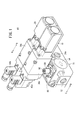
- FIG. 1 is an external perspective view of a flow control device according to a first embodiment of the present invention.
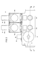
- FIG. 2 is a front view of the flow control device shown in FIG.
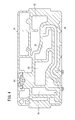
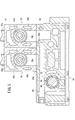
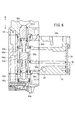
- FIG. 3 is a cross-sectional view taken along line III-III in FIG. 4 is a cross-sectional view taken along line IV-IV in FIG.
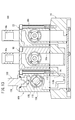
- FIG. 5 is a sectional view taken along line VV in FIG. 6 is a cross-sectional view taken along line VI-VI in FIG.
- FIG. 7 is a cross-sectional view taken along line VII-VII in FIG.
- FIG. 8 is a cross-sectional view taken along line VIII-VIII in FIG.
- FIG. 9 is a circuit diagram of the flow control device shown in FIG. FIG.
- FIG. 10 is a characteristic curve diagram showing the relationship between the pressure fluid pressure supplied to the first port and the pressure fluid pressure exhausted from the second port.
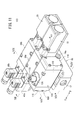
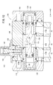
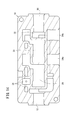
- FIG. 11 is an external perspective view of a flow control device according to the second embodiment of the present invention. 12 is a cross-sectional view taken along line XII-XII in FIG. 13 is a cross-sectional view taken along line XIII-XIII in FIG. 14 is a cross-sectional view taken along line XIV-XIV in FIG.
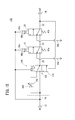
- FIG. 15 is a circuit diagram of the flow control device shown in FIG.
- the flow control device 10 includes a body 16 having first and second ports 12 and 14 through which pressure fluid is supplied and discharged, A pair of first and second solenoid valves (switching valves) 18 and 20 which are connected to the upper portion of the body 16 and switch the flow state of the pressure fluid, and under the switching action of the first and second solenoid valves 18 and 20. And an on-off valve (adjustment mechanism) 22 for increasing the flow rate of the pressure fluid circulating in the air.
- the body 16 has, for example, a rectangular cross section and is elongated along the horizontal direction.
- the first port 12 is open at one end of the body 16 and the second port 14 is open at the other end.
- the first port 12 is connected to a pressure fluid supply source (not shown) to supply pressure fluid
- the second port 14 is connected to, for example, a fluid pressure device (not shown).
- a pair of exhaust ports 24a and 24b opened in a direction orthogonal to the first and second ports 12 and 14 are formed on the side surface of the body 16 (see FIGS. 2 and 3), and the exhaust ports 24a and 24b are formed. Is connected to a pipe (not shown) and is open to the atmosphere.
- the first flow path 26 communicated with the first port 12 and the first flow path 26 in the open state of the on-off valve 22 described later.
- a second flow path 28 communicating with the second flow path 28 a third flow path 30 communicating with the second flow path 28 under the switching action by the first electromagnetic valve 18, and a third flow path under the switching action by the second electromagnetic valve 20.
- a fourth flow path 32 communicating with the path 30 is formed.
- a communication chamber 34 that connects the first channel 26 and the second channel 28 is formed between the first channel 26 and the second channel 28, and the communication chamber 34 has a first flow channel.
- An on-off valve 22 that can adjust the flow rate of the pressure fluid flowing from the passage 26 to the second passage 28 is provided.
- the third flow path 30 communicates with the inside of the first electromagnetic valve 18 connected to the upper part of the body 16, and the fourth flow path 32 of the second electromagnetic valve 20 connected to the upper part of the body 16. It communicates with the internal and second port 14.
- the first and second solenoid valves 18 and 20 are formed in substantially the same shape, and are connected to the body 16, and the housings 36a and 36b.
- 36b, shaft valves 38a, 38b, which are slidably provided along the axial direction (arrow A, B direction), and the end portions of the housings 36a, 36b are connected to the shaft valves 38a, 38b in the axial direction ( Solenoid parts 40a and 40b displaced in the directions of arrows A and B, and springs 42a and 42b for urging the shaft valves 38a and 38b toward the solenoid parts 40a and 40b (in the direction of arrow A).
- the first solenoid valve 18 and the second solenoid valve 20 are arranged in series between the first port 12 and the second port 14 as shown in FIG.
- the configuration of the first electromagnetic valve 18 will be described with reference to FIG. 6, and the configuration of the second electromagnetic valve 20 is basically the same as the configuration of the first electromagnetic valve 18. The description will be omitted and the reference numerals will be given in parentheses.
- the housing 36a (36b) constituting the first electromagnetic valve 18 is formed with a shaft hole 44a (44b) penetrating along the axial direction (directions of arrows A and B), and the shaft is formed inside the shaft hole 44a (44b).
- a valve 38a (38b) is provided to be displaceable.
- the housing 36a (36b) is formed with first to third communication passages 46a (46b), 48a (48b), 50a (50b) extending in a direction orthogonal to the shaft hole 44a (44b),
- the first communication path 46 a communicates with the second flow path 28 of the body 16, the second communication path 48 a communicates with the third flow path 30 of the body 16, and the third communication path 50 a communicates with the body 16. It communicates with the exhaust port 24a.
- the first to third communication passages 46a (46b), 48a (48b), 50a (50b) are formed at predetermined intervals along the axial direction (arrow A, B direction) of the housing 36a (36b). Is done.
- the shaft hole 44a (44b) is formed with first and second valve seats 52a (52b) and 54a (54b) on which the valve portion 56a (56b) of the shaft valve 38a (38b) is seated, and the valve portion 56a ( 56b) is disposed between the first valve seat 52a (52b) and the second valve seat 54a (54b).
- the shaft valve 38a is displaced in the axial direction (arrow A direction), and the valve portion 56a is seated on the first valve seat 52a, whereby the second flow path 28 through the first and second communication passages 46a and 48a. And the communication with the third flow path 30 are blocked.
- the shaft valve 38a is displaced in the opposite direction (arrow B direction)
- the valve portion 56a is seated on the second valve seat 54a, and the third through the second and third communication passages 48a and 50a. The communication between the flow path 30 and the exhaust port 24a is blocked.
- the shaft valve 38a (38b) is provided with a spring 42a (42b) between one end thereof and the housing 36a (36b), and the shaft valve 38a (38b) is connected to the solenoid unit 40a (40b) side (arrow). A direction). Accordingly, the valve portion 56a (56b) of the shaft valve 38a (38b) is seated on the first valve seat 52a (52b).
- the solenoid unit 40a (40b) is excited by inputting a control signal from a controller (not shown) to a coil (not shown), and is supplied to a pilot supply port 58a (58b) communicating with the first flow path 26 of the body 16.
- the pilot air is supplied to the first piston chamber 60a (60b).
- the 1st piston 62a (62b) provided in the 1st piston chamber 60a (60b) so that displacement was possible is pushed and displaced to the housing 36a (36b) side (arrow B direction) with pilot air.
- the first piston 62a (62b) is provided in contact with the other end portion of the shaft valve 38a (38b) provided in the housing 36a (36b), and the first piston 62a (62b) is displaced to displace the first piston 62a (62b).
- the shaft valve 38a (38b) is pressed against the elastic force of the spring 42a (42b). Accordingly, the valve portion 56a (56b) is separated from the first valve seat 52a (52b) and displaced so as to be seated on the second valve seat 54a (54b).
- first to third communication passages 46 b, 48 b, 50 b are formed in the housing 36 b constituting the second electromagnetic valve 20, and the first communication passage 46 b is the first communication passage 46 b of the body 16.
- the second communication path 48 b communicates with the fourth flow path 32 of the body 16, and the third communication path 50 b communicates with the exhaust port 24 b in the body 16.
- the first and second electromagnetic valves 18 and 20 are three-port valves as described above.
- the on-off valve 22 is provided so as to be orthogonal to the extending direction of the first port 12, and is inserted into the body 16 through an opening opened on the side surface of the body 16. The opening is closed by the first and second cover members 64 and 66, respectively.
- the on-off valve 22 includes a second piston 68 that is displaced along the axial direction (the directions of the arrows C and D) under the action of supplying a pressure fluid, and a push rod 70 that is in contact with the second piston 68 and is integrally displaced. And a valve body 72 that is attached to the end of the push rod 70 and switches the communication state between the first flow path 26 and the second flow path 28 in the body 16, and the valve body 72 is connected to a valve seat 74 (arrow C). And a return spring 76 biased toward the direction).
- the second piston 68 is provided in the second piston chamber 80, and an annular piston packing 78 is mounted on the outer peripheral surface thereof.
- the second piston chamber 80 communicates with the fourth flow path 32 on the outer peripheral side thereof, and pressure fluid is supplied from the fourth flow path 32 to the second piston chamber 80, so that the second piston 68. Is biased toward the valve body 72 (in the direction of arrow D).
- the valve body 72 is formed of an elastic material such as rubber, for example, and is disposed on the outer peripheral side of the other end portion of the push rod 70.
- a return spring 76 is interposed between the outer edge portion of the holder 82 and a spring holder 84 provided on the body 16.
- the return spring 76 urges the valve body 72 through the holder 82 toward the annular valve seat 74 formed on the body 16 (in the direction of arrow C).
- the valve seat portion 74 is formed at the boundary between the first flow path 26 and the second flow path 28.
- a throttle mechanism 86 capable of adjusting the flow rate of the pressure fluid flowing between the first flow path 26 and the second flow path 28 is provided.
- the throttle mechanism 86 includes a needle holder 88 connected to the side surface of the body 16 and a needle valve (throttle valve) 90 screwed to the needle holder 88, and the needle valve 90 is orthogonal to the push rod 70. It is provided as follows.
- the needle valve 90 is provided so as to be able to advance and retreat along the axial direction by being screwed, and by adjusting the gap between the tapered tip portion and the needle holder 88, the needle valve 90 can be moved through the gap. The flow rate of the pressure fluid flowing from the first flow path 26 to the second flow path 28 is adjusted.
- the flow control device 10 is basically configured as described above. Next, the operation and effects thereof will be described.
- a pipe (not shown) is connected to each of the first and second ports 12 and 14 and the exhaust ports 24a and 24b, and pressure fluid is supplied to the first port 12 from a pressure fluid supply source (not shown). Keep supplying.
- the valve body 72 of the on-off valve 22 is seated on the valve seat 74, the communication between the first flow path 26 and the second flow path 28 is blocked, and the first and second electromagnetic waves A state where the valves 18 and 20 are in a non-energized state and the communication of the second to fourth flow paths 28, 30, and 32 is blocked will be described as an initial state.
- the pressure fluid supplied from the first port 12 to the first flow path 26 is circulated to the second flow path 28 after being throttled to a predetermined flow rate by the throttle mechanism 86.
- the solenoid part 40b of the second solenoid valve 20 is energized.
- pilot air is supplied to the first piston chamber 60b of the second electromagnetic valve 20, and the first piston 62b is displaced accordingly, and the shaft valve 38b is integrally separated from the solenoid part 40b (arrow B).
- the valve portion 56b of the second electromagnetic valve 20 is separated from the first valve seat 52b, the first communication passage 46b and the second communication passage 48b communicate, and the pressure fluid supplied to the third flow passage 30. Is circulated to the fourth flow path 32 and then discharged from the second port 14.
- the pressure P2 of the pressure fluid discharged from the second port 14 is about half or less than the pressure P1 of the pressure fluid supplied to the first port 12 (1 / 2P1). > P2). That is, the pressure fluid supplied to the first port 12 circulates downstream through the throttle mechanism 86 toward the second flow path 28 side, so that the pressure (flow rate) is previously reduced to about half (1 / 2P1). Yes.
- the first flow is made via the communication chamber 34 by the valve opening operation of the on-off valve 22.
- the pressure fluid that flows from the first port 12 to the second port 14 by keeping the on-off valve 22 closed in the initial state.
- the flow rate of the pressure fluid flowing from the first port 12 to the second port 14 is increased with the on-off valve 22 opened after a predetermined time has elapsed from the initial state. Is possible (soft start).
- the solenoid portion 40a of the first solenoid valve 18 is brought into a non-excited state, and accordingly, the shaft The pressing force in the direction away from the solenoid part 40a with respect to the valve 38a is extinguished.
- the shaft valve 38a of the first electromagnetic valve 18 is pressed toward the solenoid part 40a (in the direction of arrow A) by the elastic force of the spring 42a, and the valve part 56a is in the first state. It sits on the valve seat 52a and the communication between the second flow path 28 and the third flow path 30 is blocked.
- the pressure fluid on the secondary side (downstream side) is exhausted from the one exhaust port 24 a to the outside through the third and fourth flow paths 30 and 32.
- the solenoid portions 40a and 40b of the first and second solenoid valves 18 and 20 are in a non-excited state, respectively.
- the pressing force in the direction away from the solenoid parts 40a, 40b with respect to the shaft valves 38a, 38b disappears.
- the shaft valves 38a and 38b of the first and second electromagnetic valves 18 and 20 have their valve portions 56a and 56b seated on the first valve seats 52a and 52b, respectively, and the second flow path 28 and the third Communication with the flow path 30 and communication with the third flow path 30 and the fourth flow path 32 are blocked.
- the pressure fluid remaining on the secondary side (downstream side) of the pressure fluid remaining in the third flow path 30 is exhausted from one exhaust port 24a to the outside, and at the same time downstream from the fourth flow path 32.
- the remaining pressure fluid is exhausted from the fourth flow path 32 to the outside through the other exhaust port 24b.
- the secondary pressure fluid can be exhausted to the outside of the body 16.
- the normal first or second solenoid valve 18 and 20 that does not have the malfunction is operated.
- the secondary side pressure fluid can be reliably exhausted to the outside.
- the opening / closing valve 22 and the first and second electromagnetic valves 18 and 20 are integrally connected to the body 16, the body 16, the opening / closing valve 22, Compared with a configuration in which the first and second solenoid valves 18 and 20 are separately provided and connected to each other via a pipe or the like, the pipe or the like is not necessary, so that the number of parts and the number of assembling steps can be reduced. At the same time, the flow control device 10 can be downsized.
- the pressure fluid supplied to the first port 12 suddenly sets the on-off valve 22 first in a closed state, so that the fluid pressure device or the like connected to the secondary side from the second port 14 is rapidly changed.
- the pressure fluid flowing to the second port 14 can be prevented from being supplied, and the flow rate (pressure) of the pressure fluid is increased by the valve opening operation of the on-off valve 22 after a predetermined time has passed. By doing so, it is possible to reliably prevent the fluid pressure device or the like from being damaged.
- the two solenoid valves, the first and second solenoid valves 18 and 20, are provided, even if one of the solenoid valves malfunctions for any reason, the remaining one that can operate normally By operating the solenoid valve, the pressure fluid remaining on the secondary side can be reliably exhausted to the outside.
- the pilot air supplied to the first and second electromagnetic valves 18 and 20 is supplied from the primary side upstream of the on-off valve 22, it is affected by the opening / closing operation of the on-off valve 22. Instead, the first and second solenoid valves 18 and 20 can be operated.
- the on-off valve 22 is provided on the upstream side (primary side) of the first and second electromagnetic valves 18 and 20, an operation failure occurs such that the on-off valve 22 cannot be closed for some reason.
- the pressure fluid remaining inside the body 16 can be suitably discharged from the exhaust ports 24a and 24b to the outside.
- first and second electromagnetic valves 18 and 20 are integrally connected to the upper portion of the body 16 and communicate with the inside of the body 16, the first and second electromagnetic valves 18 and 20 are connected. And the complicated operation
- the flow rate control device 100 includes an adjustment unit 106 having a throttle mechanism 102 and a switching mechanism 104, and the adjustment unit 106 is detachably attached to the body 16. This is different from the flow control device 10 according to the first embodiment.
- the flow control device 100 is adjusted in parallel with the first and second electromagnetic valves 18 and 20 on the upper portion of the body 16 having the first and second ports 12 and 14.
- Unit 106 is connected.
- This adjustment unit 106 is provided on the first port 12 side adjacent to the first electromagnetic valve 18, and includes a housing 108 having a rectangular cross section and an on-off valve 110 slidably provided inside the housing 108.
- a switching mechanism 104 including an aperture mechanism 102 provided on an upper portion of the housing 108.
- the switching mechanism 104 is composed of, for example, a three-port valve, and a shaft hole 112 penetrating along the longitudinal direction (arrow C, D direction) is formed inside the housing 108.
- the shaft hole 112 will be described later.
- the on-off valve 110 is housed in a freely displaceable manner. Further, first and second end covers 114 and 116 are attached to both ends of the housing 108, respectively, and the shaft hole 112 is closed.
- the housing 108 is formed with a pair of first communication passages 118a and 118b and a second communication passage 120 that penetrate downward toward the shaft hole 112 so that the first communication passages 118a and 118b are formed.
- the shaft holes 112 are disposed at one end and the other end of the shaft hole 112 in the axial direction, respectively, and the second communication path 120 is disposed at a position that is substantially the center in the axial direction.
- the first and second communication passages 118 a, 118 b, 120 have upper portions communicating with the shaft holes 112 and lower portions communicating with the first and second flow paths 26, 28 of the body 16, respectively.
- a second piston 122 is slidably accommodated so as to face the shaft hole 112, and the end of the second piston 122 is in contact with the end of the on-off valve 110. And by supplying pressure fluid to the 2nd piston chamber 124 formed in the inside of the 1st end cover 114, the 2nd piston 122 is urged toward the on-off valve 110 side (arrow C direction), Accordingly, the on-off valve 110 is pressed in a direction away from the first end cover 114 (direction of arrow C).
- the second piston chamber 124 communicates with the fourth flow path 32 formed in the body 16.
- a spring holder 126 is provided inside the second end cover 116 so as to face the shaft hole 112, and a return spring 128 is provided between the spring holder 126 and the on-off valve 110.
- the return spring 128 is formed of, for example, a coil spring, and its elastic force is urged so as to press the on-off valve 110 toward the first end cover 114 side (arrow D direction).
- the inside of the second end cover 116 communicates with the first communication path 118b.
- the on-off valve 110 is supported at the one end and the other end along the axial direction (arrows C and D) by the guide bodies 130a and 130b attached to the shaft hole 112 so as to be displaceable, and along the axial direction.
- the valve portion 132 formed in the substantially central portion is seated on the first valve seat portion 134 and the second valve seat portion 136 formed in the guide bodies 130a and 130b, so that a pair of first portions formed in the housing 108 is formed.
- the communication state between one of the first communication passages 118a and 118b and the second communication passage 120 is switched.
- it functions as a three-port valve capable of switching the communication state between the second communication path 120 and one of the first communication paths 118a and 118b under the displacement action of the on-off valve 110.
- the throttle mechanism 102 is provided on the other end side (in the direction of arrow C) of the on-off valve 110 in the housing 108, a needle holder 138 connected to the upper surface of the housing 108, and a needle valve screwed into the needle holder 138.
- (Throttle valve) 140, and the needle valve 140 is provided to be orthogonal to the on-off valve 110.
- This needle valve 140 is provided so as to be able to advance and retreat along the axial direction by being screwed, and by adjusting the gap between the tapered tip portion and the needle holder 138, the needle valve 140 can be moved through the gap.
- the flow rate of the pressure fluid flowing from the first communication path 118b to the second communication path 120 is adjusted.
- a part of the needle holder 138 and the needle valve 140 constituting the throttle mechanism 102 are provided so as to protrude at a predetermined height with respect to the upper surface of the housing 108.
- the flow control device 100 is basically configured as described above. Next, the operation and effects thereof will be described. In addition, about the operation
- the valve portion 132 of the on-off valve 110 of the adjustment unit 106 is seated on the first valve seat portion 134, and the first flow path 26 through the first communication passage 118a. Communication between the first and second flow paths 28 is interrupted, the first and second solenoid valves 18 and 20 are in a non-energized state, and communication between the second to fourth flow paths 28, 30, and 32 is interrupted.
- the state that is present will be described as the initial state.
- the pressure fluid supplied from the first port 12 to the first flow path 26 is throttled to a predetermined flow rate by the throttling mechanism 102 from the first communication path 118 b and then the second fluid passage 120 through the second communication path 120. It is in a state of being distributed to the two flow paths 28.
- the first solenoid valve 18 is energized, whereby pilot air is supplied to the first piston chamber 60a. Accordingly, the first piston 62a is displaced and the valve portion of the shaft valve 38a is moved to the first position. Separated from the valve seat 52a. The valve portion 56a is seated on the second valve seat 54a so that the first communication passage 46a and the second communication passage 48a communicate with each other, and the pressure fluid supplied to the second flow passage 28 is supplied to the third flow passage 30. Circulate to
- the pilot air is supplied to the first piston chamber 60b of the second electromagnetic valve 20 by energizing the solenoid portion 40b of the second electromagnetic valve 20 in a state where the energization of the first electromagnetic valve 18 is continued.
- the first piston 62b is displaced, the valve portion 56b of the shaft valve 38b is separated from the first valve seat 52b, and the first communication path 46b and the second communication path 48b communicate with each other and are supplied to the third flow path 30.
- the pressurized fluid flows into the fourth flow path 32, it is discharged from the second port 14.
- the pressure fluid supplied to the fourth flow path 32 flows into the second piston chamber 124 of the adjustment unit 106 as pilot air, so that the second piston 122 moves toward the on-off valve 110 side (arrow C direction). And the on-off valve 110 is moved toward the second valve seat 136 against the pressing force of the return air supplied into the second end cover 116 through the first communication passage 118b and the elastic force of the return spring 128. By pressing the valve portion 132, the valve portion 132 is separated from the first valve seat portion 134.
- the pressure fluid supplied from the first flow path 26 to the first communication path 118b is directly supplied from the other first communication path 118a to the second communication path 120 through the shaft hole 112, while the throttle mechanism The supply of the pressure fluid that has been supplied to the second communication path 120 through 102 is cut off.
- the on-off valve 110 constituting the switching mechanism 104 separates the valve portion 132 from the first valve seat portion 134 against the pressing force of the return air and the elastic force of the return spring 128 under the supply of pilot air. Then, by sitting on the second valve seat 136, the communication between the first communication path 118b and the second communication path 120 is blocked, and the other first communication path 118a and the second communication path 120 are disconnected. It has been switched to communicate.
- the timing of changing the pressure of the pressure fluid supplied from the first port 12 to the second port 14 is supplied to the second piston chamber 124, and the on-off valve 110 is moved to the second valve seat 136 side (direction of arrow C). ),
- the pressure receiving area of the second piston 122 is set so that the pilot air pressure is switched to approximately half of the return air pressure.
- the on-off valve 110 of the adjustment unit 106 is in the valve closed state in which it is seated on the first valve seat portion 134, so that the flow from the first port 12 to the second port 14 is reduced by the throttle mechanism 102.
- the on-off valve By allowing the pressure fluid to flow without passing through the throttle mechanism 102 with the valve 110 opened, the flow rate of the pressure fluid flowing from the first port 12 to the second port 14 can be increased (soft). start).
- the adjustment unit 106 having the throttle mechanism 102 and the switching mechanism 104 with respect to the body 16 constituting the flow control device 100 is provided, and the adjustment unit 106 is attached to the body 16.
- the adjustment unit 106 can be easily replaced, the maintainability of the throttle mechanism 102 and the switching mechanism 104 can be improved, and the pressure on the fluid pressure device or the like can be improved. It is possible to realize a soft start that can avoid a sudden supply of fluid.
- the switching of the supply state of the pressurized fluid by the on-off valve 110 of the switching mechanism 104 can be set in advance by the pressure receiving area of the second piston 122, it is necessary for the operator to perform the switching work each time. It is necessary to replace the return spring 128 that urges the on-off valve 110 toward the first valve seat portion 134 with another return spring having a different elasticity, and the supply state can be switched efficiently and reliably. This is preferable.
- the opening / closing valve 110 is biased toward the first valve seat portion 134 by the elastic force of the return air and the return spring 128, while the second Although the on-off valve 110 is biased toward the second valve seat 136 under the action of supplying pilot air supplied to the piston chamber 124, the present invention is not limited to such a configuration.
- the on-off valve 110 may be operated by only the return spring 128 without using air to switch the supply state of the pressure fluid.
- flow rate control device is not limited to the above-described embodiment, and various configurations can be adopted without departing from the gist of the present invention.
Landscapes
- Engineering & Computer Science (AREA)
- General Engineering & Computer Science (AREA)
- Mechanical Engineering (AREA)
- Physics & Mathematics (AREA)
- Fluid Mechanics (AREA)
- Power Engineering (AREA)
- General Physics & Mathematics (AREA)
- Automation & Control Theory (AREA)
- Magnetically Actuated Valves (AREA)
- Fluid-Driven Valves (AREA)
- Multiple-Way Valves (AREA)
- Fluid-Pressure Circuits (AREA)
Abstract
Description
一方のポートから他方のポートへと流通する前記圧力流体の流量を調整する調整機構と、
前記ポート、前記通路、前記排気ポートの連通状態を切り換える少なくとも2つ以上の切換弁と、
を備え、
前記調整機構は、一方のポートと他方のポートとの間を流通する圧力流体の流量を調整する絞り弁と、前記一方のポートと他方のポートとの連通状態を切換自在な開閉弁とを有し、前記開閉弁の切換作用下に前記圧力流体の流量を段階的に増減させることを特徴とする。
Claims (11)
- 圧力流体が供給・排出される一組のポート(12、14)と、二次側に残存した圧力流体を排気する排気ポート(24a、24b)と、前記ポート(12、14)、前記排気ポート(24a、24b)を接続し前記圧力流体が流通する通路(26、28、30、32)とを有するボディ(16)と、
一方のポート(12)から他方のポート(14)へと流通する前記圧力流体の流量を調整する調整機構と、
前記ポート(12、14)、前記通路(26、28、30、32)、前記排気ポート(24a、24b)の連通状態を切り換える少なくとも2つ以上の切換弁(18、20)と、
を備え、
前記調整機構は、一方のポート(12)と他方のポート(14)との間を流通する圧力流体の流量を調整する絞り機構(86、102)と、前記一方のポート(12)と他方のポート(14)との連通状態を切換自在な開閉弁(22、110)とを有し、前記開閉弁(22、110)の切換作用下に前記圧力流体の流量を段階的に増減させることを特徴とする流量制御装置。 - 請求項1記載の流量制御装置において、
前記切換弁(18、20)は、前記ボディ(16)に対して着脱自在に設けられることを特徴とする流量制御装置。 - 請求項2記載の流量制御装置において、
前記排気ポート(24a、24b)は、前記切換弁(18、20)の数量に応じて同数設けられることを特徴とする流量制御装置。 - 請求項1記載の流量制御装置において、
前記切換弁(18、20)は、3ポート弁であり、且つ、互いに直列となるように配置されることを特徴とする流量制御装置。 - 請求項1記載の流量制御装置において、
前記調整機構は、前記ボディ(16)に対して着脱自在に設けられることを特徴とする流量制御装置。 - 請求項4記載の流量制御装置において、
前記切換弁(18、20)は、通電作用下に励磁するソレノイド部(40a、40b)を有した電磁弁であることを特徴とする流量制御装置。 - 請求項1記載の流量制御装置において、
前記絞り機構(86、102)は、軸方向に進退動作するニードル弁(90、140)を有し、前記ニードル弁(90、140)を変位させることで流量を調整することを特徴とする流量制御装置。 - 請求項1記載の流量制御装置において、
前記一方のポート(12)から他方のポート(14)へと流通する圧力流体の流量は、その流通初期状態において、前記絞り機構(86、102)によって絞られて減少すると共に、前記開閉弁(22、110)を切り換えることで前記流量を増加させることを特徴とする流量制御装置。 - 請求項8記載の流量制御装置において、
前記開閉弁(22、110)は、スプリング(76、128)の弾発作用下に前記絞り機構(86、102)を通じた前記一方のポート(12)と他方のポート(14)との連通状態が維持され、パイロットエアの供給作用下に弾発力に抗して前記開閉弁(22、110)を変位させることで、該開閉弁(22、110)によって前記一方のポート(12)と他方のポート(14)との連通状態が切り換えられることを特徴とする流量制御装置。 - 請求項8記載の流量制御装置において、
前記開閉弁(22、110)は、スプリング(76、128)の弾発作用下に前記絞り機構(86、102)を通じた前記一方のポート(12)と他方のポート(14)との連通状態が切り換えられることを特徴とする流量制御装置。 - 請求項8記載の流量制御装置において、
前記開閉弁(22、110)は、3ポート弁であることを特徴とする流量制御装置。
Priority Applications (5)
| Application Number | Priority Date | Filing Date | Title |
|---|---|---|---|
| CN201280053381.9A CN103917787B (zh) | 2011-11-02 | 2012-10-24 | 流量控制设备 |
| DE112012004574.2T DE112012004574B4 (de) | 2011-11-02 | 2012-10-24 | Strömungsratensteuervorrichtung |
| KR1020147014909A KR101649883B1 (ko) | 2011-11-02 | 2012-10-24 | 유량 제어 장치 |
| JP2013541714A JP6061227B2 (ja) | 2011-11-02 | 2012-10-24 | 流量制御装置 |
| US14/353,416 US9372485B2 (en) | 2011-11-02 | 2012-10-24 | Flow rate control device |
Applications Claiming Priority (2)
| Application Number | Priority Date | Filing Date | Title |
|---|---|---|---|
| JP2011241074 | 2011-11-02 | ||
| JP2011-241074 | 2011-11-02 |
Publications (1)
| Publication Number | Publication Date |
|---|---|
| WO2013065530A1 true WO2013065530A1 (ja) | 2013-05-10 |
Family
ID=48191884
Family Applications (1)
| Application Number | Title | Priority Date | Filing Date |
|---|---|---|---|
| PCT/JP2012/077397 Ceased WO2013065530A1 (ja) | 2011-11-02 | 2012-10-24 | 流量制御装置 |
Country Status (7)
| Country | Link |
|---|---|
| US (1) | US9372485B2 (ja) |
| JP (1) | JP6061227B2 (ja) |
| KR (1) | KR101649883B1 (ja) |
| CN (1) | CN103917787B (ja) |
| DE (1) | DE112012004574B4 (ja) |
| TW (1) | TWI542794B (ja) |
| WO (1) | WO2013065530A1 (ja) |
Cited By (1)
| Publication number | Priority date | Publication date | Assignee | Title |
|---|---|---|---|---|
| JP2016512868A (ja) * | 2013-03-15 | 2016-05-09 | ロス オペレーティング バルブ カンパニーRoss Operating Valve Company | ソフトスタート機能を有する制御信頼性のある空気エネルギー遮断弁 |
Families Citing this family (6)
| Publication number | Priority date | Publication date | Assignee | Title |
|---|---|---|---|---|
| GB2540368A (en) * | 2015-07-14 | 2017-01-18 | Ge Oil & Gas Uk Ltd | Fail-safe hydraulic circuit |
| JP6684480B2 (ja) * | 2017-05-17 | 2020-04-22 | Smc株式会社 | シリンダ駆動用マニホールド装置及びシリンダ駆動装置 |
| JP1659524S (ja) * | 2019-06-14 | 2020-05-18 | ||
| JP1659525S (ja) * | 2019-09-03 | 2020-05-18 | ||
| JP1659421S (ja) * | 2019-09-03 | 2020-05-18 | ||
| DE102021123936B3 (de) | 2021-09-15 | 2023-01-26 | Aventics Gmbh | Sicherheitsventil |
Citations (7)
| Publication number | Priority date | Publication date | Assignee | Title |
|---|---|---|---|---|
| JPS55144202U (ja) * | 1979-04-05 | 1980-10-16 | ||
| JPS6119207Y2 (ja) * | 1980-11-18 | 1986-06-10 | ||
| JPH0735106A (ja) * | 1993-07-27 | 1995-02-03 | Ckd Corp | エアシリンダ駆動制御回路及び流量制御弁 |
| JP3016029U (ja) * | 1995-03-08 | 1995-09-26 | 川崎重工業株式会社 | メンテナンスバルブ |
| JP2544693Y2 (ja) * | 1992-04-30 | 1997-08-20 | エスエムシー株式会社 | 安全制御装置 |
| JP2565816Y2 (ja) * | 1993-07-09 | 1998-03-25 | シーケーディ株式会社 | 制御弁 |
| JP3530557B2 (ja) * | 1993-10-14 | 2004-05-24 | Smc株式会社 | スロースタートバルブ |
Family Cites Families (20)
| Publication number | Priority date | Publication date | Assignee | Title |
|---|---|---|---|---|
| JPS54101069A (en) | 1978-01-27 | 1979-08-09 | Hitachi Metals Ltd | Fluid cylinder control circuit |
| JPS55126107A (en) | 1979-03-19 | 1980-09-29 | Toyooki Kogyo Co Ltd | Controller for compressed-air operated actuator |
| JPS55144202A (en) | 1979-04-29 | 1980-11-11 | Matsushita Electric Works Ltd | Optical fiber switch device |
| SE418523B (sv) | 1979-07-20 | 1981-06-09 | Mecman Ab | Ventilanordning for anslutning till en tryckmediekella och kontrollerad tryckmedietillforsel till och tryckuppbyggnad i ett tryckmediesystem |
| JPS6119207A (ja) | 1984-07-05 | 1986-01-28 | Murata Mfg Co Ltd | ラインフイルタ |
| JPH0419207Y2 (ja) | 1985-12-27 | 1992-04-30 | ||
| JP3016029B2 (ja) | 1988-10-31 | 2000-03-06 | 理想科学工業株式会社 | 画像処理装置 |
| JP2683104B2 (ja) | 1989-06-12 | 1997-11-26 | キヤノン株式会社 | 情報記録再生装置 |
| US5067519A (en) * | 1990-11-26 | 1991-11-26 | Ross Operating Valve Company | Safety valve for fluid systems |
| JPH086727B2 (ja) * | 1991-04-09 | 1996-01-29 | エスエムシー株式会社 | スロースタートバルブ |
| JP2544693B2 (ja) | 1992-09-28 | 1996-10-16 | 西日本旅客鉄道株式会社 | 鉄道車両の洗滌装置 |
| US5337788A (en) | 1993-10-22 | 1994-08-16 | Robertshaw Controls Company | Pneumatic valve with slow start and quick exhaust |
| JP3153466B2 (ja) * | 1995-04-07 | 2001-04-09 | シーケーディ株式会社 | スロースタートバルブ |
| US5669422A (en) | 1995-04-07 | 1997-09-23 | Ckd Corporation | Slow start valve |
| DE202004015468U1 (de) * | 2004-10-06 | 2005-01-05 | Festo Ag & Co.Kg | Softstartvorrichtung für Druckluftsysteme |
| JP4690827B2 (ja) * | 2005-08-26 | 2011-06-01 | 株式会社フジキン | ガスケット型オリフィス及びこれを用いた圧力式流量制御装置 |
| US20070205384A1 (en) * | 2006-03-02 | 2007-09-06 | Smc Kabushiki Kaisha | Flow Rate Control Apparatus |
| EP2047108B1 (de) | 2006-12-05 | 2010-01-06 | Festo AG & Co. KG | Softstart-ventileinrichtung |
| EP1930638B1 (de) * | 2006-12-05 | 2011-01-05 | FESTO AG & Co. KG | Softstart-Ventileinrichtung |
| WO2009100734A1 (de) * | 2008-02-15 | 2009-08-20 | Festo Ag & Co. Kg | Softstartvorrichtung für druckluftsysteme und verfahren zum betreiben einer softstartvorrichtung |
-
2012
- 2012-10-24 US US14/353,416 patent/US9372485B2/en active Active
- 2012-10-24 KR KR1020147014909A patent/KR101649883B1/ko active Active
- 2012-10-24 JP JP2013541714A patent/JP6061227B2/ja active Active
- 2012-10-24 CN CN201280053381.9A patent/CN103917787B/zh active Active
- 2012-10-24 DE DE112012004574.2T patent/DE112012004574B4/de active Active
- 2012-10-24 WO PCT/JP2012/077397 patent/WO2013065530A1/ja not_active Ceased
- 2012-10-30 TW TW101140061A patent/TWI542794B/zh active
Patent Citations (7)
| Publication number | Priority date | Publication date | Assignee | Title |
|---|---|---|---|---|
| JPS55144202U (ja) * | 1979-04-05 | 1980-10-16 | ||
| JPS6119207Y2 (ja) * | 1980-11-18 | 1986-06-10 | ||
| JP2544693Y2 (ja) * | 1992-04-30 | 1997-08-20 | エスエムシー株式会社 | 安全制御装置 |
| JP2565816Y2 (ja) * | 1993-07-09 | 1998-03-25 | シーケーディ株式会社 | 制御弁 |
| JPH0735106A (ja) * | 1993-07-27 | 1995-02-03 | Ckd Corp | エアシリンダ駆動制御回路及び流量制御弁 |
| JP3530557B2 (ja) * | 1993-10-14 | 2004-05-24 | Smc株式会社 | スロースタートバルブ |
| JP3016029U (ja) * | 1995-03-08 | 1995-09-26 | 川崎重工業株式会社 | メンテナンスバルブ |
Cited By (1)
| Publication number | Priority date | Publication date | Assignee | Title |
|---|---|---|---|---|
| JP2016512868A (ja) * | 2013-03-15 | 2016-05-09 | ロス オペレーティング バルブ カンパニーRoss Operating Valve Company | ソフトスタート機能を有する制御信頼性のある空気エネルギー遮断弁 |
Also Published As
| Publication number | Publication date |
|---|---|
| US9372485B2 (en) | 2016-06-21 |
| CN103917787A (zh) | 2014-07-09 |
| DE112012004574B4 (de) | 2018-03-08 |
| DE112012004574T5 (de) | 2014-08-14 |
| KR20140097281A (ko) | 2014-08-06 |
| KR101649883B1 (ko) | 2016-08-22 |
| CN103917787B (zh) | 2017-05-24 |
| JPWO2013065530A1 (ja) | 2015-04-02 |
| TW201341672A (zh) | 2013-10-16 |
| US20140264106A1 (en) | 2014-09-18 |
| TWI542794B (zh) | 2016-07-21 |
| JP6061227B2 (ja) | 2017-01-18 |
Similar Documents
| Publication | Publication Date | Title |
|---|---|---|
| JP6061227B2 (ja) | 流量制御装置 | |
| JP2002099331A (ja) | 流体圧力調整装置 | |
| KR20120115111A (ko) | 파일럿식 3위치 스위칭 밸브 | |
| KR100720070B1 (ko) | 유압 회로 및 그 밸브 장치 | |
| JP7700528B2 (ja) | エジェクタ及びこれを備える真空発生装置 | |
| JP2011153709A5 (ja) | ||
| CA2957232C (en) | Proportional pressure controller with isolation valve assembly | |
| JP5561528B2 (ja) | リリーフ圧力変更機能付きリリーフバルブ | |
| JP2017133629A5 (ja) | ||
| US20250003502A1 (en) | Improved double safety valve | |
| JP6966961B2 (ja) | 制御弁 | |
| EP2689142B1 (en) | Valve | |
| JP2011202706A (ja) | 三方電磁弁 | |
| WO2003104695A1 (ja) | 電磁弁 | |
| KR101505016B1 (ko) | 복동식 왕복가능 압력 부스터용 자동 압력조절 제어 기구 | |
| CN111561573B (zh) | 流量控制阀 | |
| JP4205499B2 (ja) | オールポートクローズ形バルブ | |
| JP2544804Y2 (ja) | 方向制御弁装置 | |
| JP5791351B2 (ja) | 複合電磁切換弁 | |
| JPWO2023176686A5 (ja) | ||
| JP4504144B2 (ja) | 開閉弁及びこの開閉弁を用いた射出制御用油圧装置 | |
| KR101216675B1 (ko) | 중압집중 배기구조를 갖는 아이에스오 솔레노이드 밸브 | |
| JPH0375762B2 (ja) | ||
| JP2022137775A (ja) | 弁装置とこれを用いた減圧弁 | |
| JP2014211207A (ja) | 油圧制御バルブおよび油圧制御装置 |
Legal Events
| Date | Code | Title | Description |
|---|---|---|---|
| 121 | Ep: the epo has been informed by wipo that ep was designated in this application |
Ref document number: 12846422 Country of ref document: EP Kind code of ref document: A1 |
|
| ENP | Entry into the national phase |
Ref document number: 2013541714 Country of ref document: JP Kind code of ref document: A |
|
| WWE | Wipo information: entry into national phase |
Ref document number: 14353416 Country of ref document: US |
|
| WWE | Wipo information: entry into national phase |
Ref document number: 112012004574 Country of ref document: DE Ref document number: 1120120045742 Country of ref document: DE |
|
| ENP | Entry into the national phase |
Ref document number: 20147014909 Country of ref document: KR Kind code of ref document: A |
|
| 122 | Ep: pct application non-entry in european phase |
Ref document number: 12846422 Country of ref document: EP Kind code of ref document: A1 |