WO2013051550A1 - X線診断装置及び線量管理方法 - Google Patents
X線診断装置及び線量管理方法 Download PDFInfo
- Publication number
- WO2013051550A1 WO2013051550A1 PCT/JP2012/075492 JP2012075492W WO2013051550A1 WO 2013051550 A1 WO2013051550 A1 WO 2013051550A1 JP 2012075492 W JP2012075492 W JP 2012075492W WO 2013051550 A1 WO2013051550 A1 WO 2013051550A1
- Authority
- WO
- WIPO (PCT)
- Prior art keywords
- ray
- dose
- distribution data
- generation unit
- incident
- Prior art date
- Legal status (The legal status is an assumption and is not a legal conclusion. Google has not performed a legal analysis and makes no representation as to the accuracy of the status listed.)
- Ceased
Links
Images


Classifications
-
- A—HUMAN NECESSITIES
- A61—MEDICAL OR VETERINARY SCIENCE; HYGIENE
- A61B—DIAGNOSIS; SURGERY; IDENTIFICATION
- A61B6/00—Apparatus or devices for radiation diagnosis; Apparatus or devices for radiation diagnosis combined with radiation therapy equipment
- A61B6/54—Control of apparatus or devices for radiation diagnosis
- A61B6/542—Control of apparatus or devices for radiation diagnosis involving control of exposure
-
- A—HUMAN NECESSITIES
- A61—MEDICAL OR VETERINARY SCIENCE; HYGIENE
- A61B—DIAGNOSIS; SURGERY; IDENTIFICATION
- A61B6/00—Apparatus or devices for radiation diagnosis; Apparatus or devices for radiation diagnosis combined with radiation therapy equipment
- A61B6/42—Arrangements for detecting radiation specially adapted for radiation diagnosis
- A61B6/4208—Arrangements for detecting radiation specially adapted for radiation diagnosis characterised by using a particular type of detector
- A61B6/4233—Arrangements for detecting radiation specially adapted for radiation diagnosis characterised by using a particular type of detector using matrix detectors
-
- A—HUMAN NECESSITIES
- A61—MEDICAL OR VETERINARY SCIENCE; HYGIENE
- A61B—DIAGNOSIS; SURGERY; IDENTIFICATION
- A61B6/00—Apparatus or devices for radiation diagnosis; Apparatus or devices for radiation diagnosis combined with radiation therapy equipment
- A61B6/44—Constructional features of apparatus for radiation diagnosis
- A61B6/4429—Constructional features of apparatus for radiation diagnosis related to the mounting of source units and detector units
- A61B6/4435—Constructional features of apparatus for radiation diagnosis related to the mounting of source units and detector units the source unit and the detector unit being coupled by a rigid structure
- A61B6/4441—Constructional features of apparatus for radiation diagnosis related to the mounting of source units and detector units the source unit and the detector unit being coupled by a rigid structure the rigid structure being a C-arm or U-arm
-
- A—HUMAN NECESSITIES
- A61—MEDICAL OR VETERINARY SCIENCE; HYGIENE
- A61B—DIAGNOSIS; SURGERY; IDENTIFICATION
- A61B6/00—Apparatus or devices for radiation diagnosis; Apparatus or devices for radiation diagnosis combined with radiation therapy equipment
- A61B6/48—Diagnostic techniques
- A61B6/481—Diagnostic techniques involving the use of contrast agents
-
- A—HUMAN NECESSITIES
- A61—MEDICAL OR VETERINARY SCIENCE; HYGIENE
- A61B—DIAGNOSIS; SURGERY; IDENTIFICATION
- A61B6/00—Apparatus or devices for radiation diagnosis; Apparatus or devices for radiation diagnosis combined with radiation therapy equipment
- A61B6/50—Apparatus or devices for radiation diagnosis; Apparatus or devices for radiation diagnosis combined with radiation therapy equipment specially adapted for specific body parts; specially adapted for specific clinical applications
- A61B6/504—Apparatus or devices for radiation diagnosis; Apparatus or devices for radiation diagnosis combined with radiation therapy equipment specially adapted for specific body parts; specially adapted for specific clinical applications for diagnosis of blood vessels, e.g. by angiography
Definitions
- Embodiments of the present invention relate to a technique of an X-ray diagnostic apparatus and a dose management method.
- An X-ray diagnostic apparatus irradiates a patient with X-rays from an X-ray tube, captures X-rays transmitted through a subject with an X-ray detector, etc., and is a fluoroscopic image or a captured image that is a shadow image proportional to the transmitted dose. Is generated.
- An operator such as a doctor or a laboratory technician (hereinafter simply referred to as “operator”) diagnoses the subject by observing a fluoroscopic image or a captured image generated by the X-ray diagnostic apparatus.
- the intensity distribution of the X-rays emitted from the X-ray tube may vary depending on the configuration of the X-ray diagnostic apparatus and the imaging conditions. For example, when the electron beam collides with the anode in the X-ray tube and X-rays are generated, the intensity distribution of the X-rays generated by the heel effect may vary. Further, the intensity of X-rays that pass through a part of the irradiation field may be reduced depending on the conditions of the X-ray diaphragm and the filter.
- the problem to be solved by the present invention is to make it possible to manage the incident dose for each predetermined region in the irradiation field even under conditions in which the X-ray intensity distribution varies in the irradiation field.
- a first aspect of this embodiment is an X-ray diagnostic apparatus that detects an X-ray output from an X-ray source and transmitted through a subject and generates an image in the subject.
- the X-ray diagnostic apparatus includes a detection unit, an X-ray intensity distribution data generation unit, and an incident dose distribution data generation unit.
- the detection unit detects the intensity of the X-ray output from the X-ray source.
- the X-ray intensity distribution data generation unit generates X-ray intensity distribution data indicating the X-ray intensity for each of the plurality of partial regions of the X-ray irradiation field from the X-ray source based on the detection result by the detection unit.
- the incident dose distribution data generation unit generates incident dose distribution data indicating the X-ray dose output from the X-ray source and incident on the subject based on the X-ray intensity distribution data.
- An example of the X-ray intensity distribution in the irradiation field is shown. It is the graph which showed the relationship between SN ratio of X-ray intensity, and incident dose. It is a figure for demonstrating distribution data. It is a figure for demonstrating the relationship between a top plate and an incident dose. It is a figure for demonstrating the relationship between a compensation filter and incident dose. It is a figure for demonstrating the relationship between a compensation filter and incident dose. It is a figure for demonstrating the relationship between a compensation filter and incident dose. It is a figure for demonstrating the relationship between a compensation filter and incident dose.
- An example of an incident dose management method is shown. An example of an incident dose management method is shown. It is an example of the display mode of the information which shows incident dose. It is an example of the display mode of the information which shows incident dose. It is the flowchart which showed the flow of the process which concerns on the production
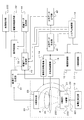
- the X-ray diagnostic apparatus includes an imaging unit 20, a system control unit 10, an X-ray control unit 11, a high voltage generation unit 12, a mechanism control unit 13, and an imaging.
- the imaging unit 20 includes a C-arm 21, an X-ray generation unit 22, an X-ray detector 23, and a top plate 24.
- the C-arm 21 is a holding unit that holds the X-ray generation unit 22 and the X-ray detector 23.
- An X-ray generator 22 is held at one end of the C-arm 21.
- An X-ray detector 23 is held at the other end of the C arm 21 so as to face the X-ray generator 22.
- the C-arm 21 is rotatably supported by, for example, an arc-shaped column suspended from the ceiling. Between the X-ray generator 22 and the X-ray detector 23, a couch top 24 for placing the subject P is disposed.
- the X-ray generation unit 22 is configured to irradiate X-rays toward the subject P placed on the top plate 24 interposed between the X-ray detector 23.
- the X-ray detector 23 detects X-rays emitted from the X-ray generator 22.
- the imaging system moving mechanism 14 is a drive unit for moving and rotating the C-arm 21.
- the top plate moving mechanism 15 is a drive unit for moving the top plate 24.
- the imaging system moving mechanism 14 and the top board moving mechanism 15 operate based on control from the mechanism control unit 13. Specifically, the mechanism control unit 13 generates information indicating the direction, amount, and speed of rotation and movement of the C arm 21 and the X-ray detector 23 according to the control signal supplied from the system control unit 10. To do. The system control unit 10 will be described later.
- the mechanism control unit 13 outputs the generated information to the imaging system moving mechanism 14.
- the imaging system moving mechanism 14 controls the position and orientation of the C arm 21 by moving and rotating the C arm 21 based on this information.
- the mechanism control unit 13 generates information indicating the direction, the moving amount, and the speed in the movement of the top plate 24 according to the control signal from the system control unit 10.
- the mechanism control unit 13 outputs the generated information to the top board moving mechanism 15. Based on this information, the top plate moving mechanism 15 controls the position of the top plate 24 so as to move the top plate 24 along the body axis direction of the subject P.
- the X-ray generation unit 22 includes an X-ray tube 221, an X-ray diaphragm 222, and an area dosimeter 223.
- the X-ray tube 221 accelerates electrons emitted from the filament with a high voltage, and collides against an anode target to generate X-rays, and irradiates the X-rays to the outside through an irradiation window.
- As the target material for example, tungsten is used.
- the X-ray diaphragm 222 is provided in the irradiation window of the X-ray tube 221 and is composed of a plurality of lead feathers.
- the X-ray diaphragm 222 narrows down to a predetermined irradiation field size so that unnecessary portions other than the observation site are not exposed by the X-rays irradiated from the X-ray tube 221.
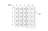
- a compensation filter M1 that is formed of acrylic or the like and that attenuates X-rays in a predetermined region within the irradiation field by a predetermined amount may be provided on the emission side of the X-ray diaphragm 222.
- the area dosimeter 223 detects the X-ray dose that has passed through the X-ray diaphragm 222.
- the area dosimeter 223 converts the detected X-ray dose into electric charges, and outputs the charges to the distribution data generation unit 41 or the dose data generation unit 43 as an area dose output signal.
- This area dose output signal is substantially proportional to the X-ray irradiation intensity, irradiation area, and irradiation time.
- the distribution data generation unit 41 and the dose data generation unit 43 will be described later.
- the output signal of the area dosimeter 223 may be referred to as a reference position (hereinafter referred to as a “dose calculation reference position”) that is a predetermined distance away from the rotation center (ie, isocenter) of the C arm 21 toward the X-ray tube.
- the dose at the reference position (hereinafter, sometimes referred to as “air kerma”) is calculated by dividing by the area of (some).
- air kerma is output as an air kerma.
- the high voltage generator 12 generates a high voltage to be applied between the anode and the cathode in order to accelerate the thermal electrons generated from the cathode of the X-ray tube 221.
- the operation of the high voltage generator 12 is controlled by the X-ray controller 11.
- the X-ray control unit 11 receives control information indicating an X-ray irradiation condition from the system control unit 10. Based on this control information, the X-ray control unit 11 performs X-ray irradiation conditions including tube current, tube voltage, X-ray pulse width, irradiation period (rate interval), fluoroscopic section, and the like for operating the high voltage generation unit 12. Generates information indicating The X-ray controller 11 controls the operation of the high voltage generator 12 based on this information.
- the X-ray detector 23 is composed of, for example, a flat panel detector (FPD: planar X-ray detector) having a plurality of detection elements arranged in a matrix.
- the X-ray detector 23 detects the intensity of the X-rays emitted from the X-ray generator 22 in a predetermined irradiation field for each detection element.
- An X-ray grid for cutting X-ray scattered light transmitted through a predetermined part of the subject P may be provided on the surface of the FPD on the top plate 24 side.
- the X-ray detector 23 converts the X-ray intensity detected for each detection element into an electric signal, and outputs it as image data to the distribution data generation unit 41 or the image data generation unit 31.
- the distribution data generation unit 41 and the image data generation unit 31 will be described later.
- the X-ray detector 23 replaces the FPD with an X-ray I.D. I. You may comprise by the combination of (image intensifier) and a X-ray TV camera.
- the image data generation unit 31 receives image data from the X-ray detector 23 and performs image calculation and image processing on the image data. For example, the image data generation unit 31 performs image calculation to generate DSA (Digital Subtraction Angiography) image data, road map image data, long image data, and the like by subtraction between image data before and after contrast agent injection. Further, the image data generation unit 31 performs image processing such as contour extraction, smoothing, and gradation change on the image data obtained by the image calculation. Further, the image data generation unit 31 receives information indicating the X-ray examination conditions regarding the image data from the system control unit 10.
- DSA Digital Subtraction Angiography
- the image data generation unit 31 attaches information indicating the X-ray examination conditions to the image data obtained by image calculation and image processing, and outputs the information to the display control unit 32. In response to this, the display control unit 32 displays an X-ray image on the image display unit 332 based on the image data.
- the system control unit 10 constitutes the control center of the entire system, receives X-ray irradiation conditions and imaging position conditions input by an operator as X-ray examination conditions, and receives an X-ray control unit 11 and a mechanism control unit 13. To control the operation. Specifically, the system control unit 10 generates a control signal based on the X-ray irradiation conditions input by the operator, and controls the operation of the X-ray control unit 11 based on the control signal. In response to this control signal, the X-ray controller 11 operates the high voltage generator 12 to irradiate the X-ray from the X-ray generator 22.
- system control unit 10 generates a control signal based on the photographing position condition input by the operator, and controls the operation of the mechanism control unit 13 based on the control signal. With this control signal, the mechanism control unit 13 operates the imaging system moving mechanism 14 and the top plate moving mechanism 15 to control the movement and rotation of the C arm 21 and the movement of the top plate 24.
- system control unit 10 outputs information indicating the X-ray examination conditions to the distribution data generation unit 41, the dose data generation unit 43, and the image data generation unit 31.
- the distribution data generation unit 41 and the dose data generation unit 43 will be described later.
- the X-ray inspection apparatus has a function of managing the exposure dose of the subject P accompanying the X-ray irradiation based on the area dose output signal from the area dosimeter 223.
- the X-ray intensity distribution in the irradiation field of the X-rays irradiated from the X-ray generation unit 22 will be described with reference to FIG.
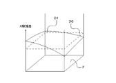
- FIG. 2 shows an example of the X-ray intensity distribution in the irradiation field.
- D0 in FIG. 2 shows a case where the X-ray intensity distribution in the irradiation field is uniform.
- the X-ray intensity distribution in the irradiation field varies due to various factors, and the X-ray intensity distribution may not be uniform as indicated by D1.
- the X-ray intensity tends to decrease in an angular direction close to the anode surface due to the heel effect.
- the compensation filter M1 when used, the X-ray intensity decreases in the region where the compensation filter M1 is applied.
- distribution data indicating the distribution of the X-ray intensity according to the present embodiment is generated in advance, and the X-ray intensity is calculated for each region in the irradiation field using the distribution data at the time of X-ray inspection.
- a configuration that operates in each process will be described, divided into a “preparation stage” for generating distribution data and an “inspection stage” for calculating the incident dose of X-rays. .
- the X-ray inspection apparatus generates and stores distribution data indicating an X-ray intensity distribution in advance for each X-ray irradiation condition as a preparation stage before the X-ray inspection.
- This distribution data generation method will be described below with a focus on a configuration for generating distribution data.
- the generation of the distribution data is performed in a state where the X-ray grid of the X-ray detector 23 is removed and the top plate 24 and the compensation filter M1 are not interposed between the X-ray generator 22 and the X-ray detector 23.
- the system control unit 10 receives an X-ray examination condition input by an operator, generates a control signal based on the condition, and outputs the generated control signal to the X-ray control unit 11 and the mechanism control unit 13. .
- the X-ray control unit 11 and the mechanism control unit 13 are operated based on this control signal, so that the C-arm 21 is operated and rotated so as to be at a predetermined imaging position, and determined based on the X-ray irradiation conditions.
- X-rays are irradiated from the X-ray generator 22 toward a predetermined irradiation field. Further, the system control unit 10 outputs information indicating the X-ray examination conditions to the distribution data generation unit 41. Details of the distribution data generation unit 41 will be described later.
- the area dosimeter 223 detects the X-ray dose irradiated from the X-ray tube 221 and passed through the X-ray diaphragm 222. In the preparation stage, the area dosimeter 223 converts the detected X-ray dose into an electric charge, and outputs it to the distribution data generation unit 41 as an area dose output signal. Note that, for example, the system control unit 10 recognizes whether the X-ray inspection apparatus is operating as the “preparation stage” or the “inspection stage” upon receiving an operation by the operator.
- the X-ray detector 23 detects the intensity of the X-rays emitted from the X-ray generator 22 for each detection element.
- the X-ray detector 23 converts the X-ray intensity detected for each detection element into an electrical signal, and outputs the electrical signal to the distribution data generation unit 41.
- the distribution data generation unit 41 receives image data for each detection element from the X-ray detector 23.
- the distribution data generation unit 41 previously divides an area where X-rays are detected as image data (that is, an irradiation field) into a plurality of areas.
- the distribution data generation unit 41 uses the X-ray generation unit 22 as a reference and the region at the dose calculation reference position for each divided region based on the distance to the X-ray detector 23 and the distance to the dose calculation reference position. Convert to.
- Each area at the dose calculation reference position is referred to as a “management unit area”.
- the distribution data generation unit 41 calculates an X-ray SN ratio for each management unit region.
- the method of using the distribution data of the output of the X-ray detector 23 is simple, generally the output of an X-ray detector such as an FPD is obtained by correcting variations in the X-ray intensity distribution and the sensitivity of the detector itself. Since it is output, it is difficult to divert it to X-ray intensity distribution data.
- a method for calculating the SN ratio of the X-ray for each management unit area will be specifically described below.
- the distribution data generation unit 41 calculates the SD value (standard deviation) of the X-ray intensity based on the average X-ray intensity for each detection element and the variance of the X-ray intensity in each detection element for each management unit region. .
- the distribution data generation unit 41 divides the average of the X-ray intensities by the calculated SD value, thereby obtaining the ratio of the average (output level) of the X-ray intensity of the management unit area and the SD value in the management unit area. Calculated as the S / N ratio of X-rays. That is, the calculated SD value of the X-ray intensity corresponds to a noise portion in the calculation of the SN ratio.
- the distribution data generation unit 41 measures the relationship between the S / N ratio of X-rays and the incident dose in advance as a characteristic of the X-ray detector 23 and stores it as characteristic data.
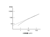
- FIG. 3A is a graph showing the relationship between the S / N ratio of the X-ray intensity and the incident dose as the characteristic of the X-ray detector 23, and this characteristic is caused by the X-ray quantum noise and the intrinsic noise of the X-ray detector 23.
- the generation and absorption of radiation such as X-rays is a random phenomenon. Since the frequency of radiation generation and absorption follows the laws of statistics, it involves noise. This noise corresponds to X-ray quantum noise.
- the inherent noise is noise inherent to the X-ray detector 23, such as noise of a circuit that constitutes the X-ray detector 23. As shown in FIG. 3A, the linearity is lost in the low dose region. This is due to the influence of the inherent noise of the X-ray detector 23.
- the S / N ratio of X-rays and the incident dose are in a proportional relationship. This is because when the intensity of the X-ray increases and becomes a predetermined dose or more, the influence of the intrinsic noise of the X-ray detector 23 on the X-ray quantum noise becomes small and can be ignored.
- the distribution data generation unit 41 can detect the SN ratio of the X-rays. Can be converted into an incident dose. With such a configuration, the distribution data generation unit 41 converts the SN ratio calculated for each region into the incident dose for each region based on this characteristic data. Moreover, since these distributions may change depending on the X-ray tube voltage, the quality of the quality filter, the irradiation field size, etc., data is collected under various conditions.
- the distribution data generation unit 41 generates distribution data indicating the X-ray intensity distribution under various conditions.
- the distribution data generation unit 41 has distribution data for each management unit region at the dose calculation reference position. For example, in the example of FIG. 3B, a dose obtained by dividing the total area dose by the total irradiation area (ie, air kerma) is “100” (the dose in this case may be referred to as “average dose”).
- the dose ratio (%) of each control unit area is shown. For example, the area “a3” indicates “60”. “60” indicates that the dose is 60% of the average dose.
- the region “c2” indicates “125”. “125” indicates that the dose is 125% of the average dose. That is, in FIG. 3B, the ratio is corrected so that the average of the whole becomes “100”.
- the distribution data generation unit 41 receives information from the system control unit 10 indicating the X-ray examination conditions when the distribution data is generated.
- the distribution data generation unit 41 stores the generated distribution data in the distribution data storage unit 42 in association with information indicating the X-ray examination conditions.
- the distribution data storage unit 42 is a storage area for storing distribution data.
- the distribution data storage unit 42 is configured to be able to read distribution data corresponding to the conditions by designating the conditions for the X-ray examination. As described above, the distribution data generation unit 41 generates distribution data for each condition of the X-ray examination, and stores the generated distribution data in the distribution data storage unit 42.
- the X-ray inspection apparatus irradiates the subject P with X-rays, and the area dose detected by the area dosimeter 223 and the distribution data corresponding to the X-ray inspection conditions at that time. Based on this, the incident dose for each region is calculated.
- description will be given focusing on the configuration that operates at this time.
- the system control unit 10 When the conditions for the X-ray examination are set by the operator, the system control unit 10 generates a control signal based on the conditions and outputs the control signal to the X-ray control unit 11 and the mechanism control unit 13. As a result, the C-arm 21 is operated and rotated so as to reach a predetermined photographing position. As the top plate 24 moves, X-rays are irradiated from the X-ray generator 22 toward the subject P on the top plate 24 based on the X-ray irradiation conditions. The system control unit 10 outputs information indicating the X-ray examination conditions to the image data generation unit 31 and the dose data generation unit 43. Details of the dose data generation unit 43 will be described later.
- the X-ray detector 23 detects the intensity of the X-rays emitted from the X-ray generator 22 for each detection element.
- the X-ray detector 23 converts the X-ray intensity detected for each detection element into an electric signal, and outputs it as image data to the image data generation unit 31.
- the image data generation unit 31 performs image calculation and image processing on the image data, attaches information indicating the X-ray examination conditions received from the system control unit 10 to the image data, and outputs the information to the display control unit 32.
- the area dosimeter 223 detects the dose of X-rays irradiated from the X-ray tube 221 and passing through the X-ray diaphragm 222.
- the area dosimeter 223 converts the detected X-ray dose into electric charges and outputs the charges to the dose data generation unit 43 as an area dose output signal.
- the dose data generation unit 43 receives information indicating the X-ray examination conditions from the system control unit 10.
- the dose data generation unit 43 extracts the distribution data associated with this information from the distribution data storage unit 42.
- the dose data generation unit 43 receives an area dose output signal from the area dosimeter 223.
- the area dose indicated by this output signal corresponds to the total area dose.
- the dose data generation unit 43 calculates a region where the X-ray attenuates with the use of the compensation filter M1 and the transmission through the top plate 24 and the amount of attenuation based on the information indicating the conditions of the X-ray examination.
- a description will be given of a method for calculating the amount of attenuation of X-rays by passing through the top plate 24 when the top plate 24 is interposed between the subject P and the X-ray generation unit 22.
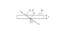
- FIG. 4A shows a case where an X-ray having an incident dose I 0 is incident on the top plate 24 having a thickness t at an incident angle ⁇ .
- the dose data generation unit 43 specifies a region where the top 24 is interposed between the subject P and the X-ray generation unit 22 in the X-ray irradiation field from information indicating the X-ray examination conditions.
- the dose data generation unit 43 calculates the amount of X-ray attenuation in the specified region.
- the attenuation amount (incident dose) of X-rays after passing through the top plate 24 is the distance t1 at which the X-rays pass through the top plate 24, u is the X-ray absorption coefficient of the top plate 24, and the incident dose I 0. Based on the above.
- the distance t1 through which the X-ray passes through the top plate 24 is calculated by the following mathematical formula.
- t1 t / cos ⁇
- the incident dose I of X-rays after passing through the top plate 24 is calculated by the following mathematical formula.
- I I 0 exp ( ⁇ u ⁇ t1)
- the attenuation calculation method is different from that when the top plate 24 is interposed. This is because the area dosimeter 223 detects X-rays that have passed through the compensation filter M1.
- FIGS. 4B to 4D are diagrams for explaining the relationship between the compensation filter M1 and the incident dose. A description will be given in a state where a part of the compensation filter M1 is inserted as shown in FIG. 4B.
- the transmittance of the compensation filter M1 is A ⁇ 100%. Further, the ratio of the portion where the compensation filter M1 is inserted to the entire area dosimeter 223 is B ⁇ 100%.
- the sum (D1) of values corresponding to each region when the value of each region is 100 and the sum (D2) of values corresponding to each region when the compensation filter M1 is applied are calculated.
- a coefficient D1 / D2 is calculated based on the calculated D1 and D2.
- FIG. 4C shows distribution data created by correcting the distribution shown in FIG. 4B by the coefficients D1 / D2. As shown in FIG. 4C, the regions a1 to a5, b1 to b5, and c1 to c5 are corrected to 125, and the regions d1 to d5 and e1 to e5 are corrected to 62.5.
- the dose data generation unit 43 when calculating the incident dose for each region, the value of distribution data extracted based on the information indicating the X-ray examination conditions, The distribution data is corrected by multiplying the value of the distribution data created based on the condition of the compensation filter M1 for each region.
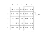
- FIG. 4D shows corrected distribution data obtained by correcting the distribution data shown in FIG. 3B based on the distribution data shown in FIG. 4C.
- a region M2 in FIG. 4D corresponds to a portion to which the compensation filter M1 is applied. For example, the region a1 indicates “90”% in FIG. 3B and is not covered with the compensation filter M1.
- the dose data generation unit 43 may calculate the X-ray attenuation amount of the corrected distribution data.
- the dose data generation unit 43 corrects the incident dose calculated for each region based on the calculated attenuation.
- the dose data generation unit 43 calculates the incident dose for each region, and generates dose data associated with the region from which the incident dose is calculated.
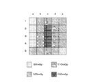
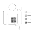
- FIG. 5A is a diagram schematically illustrating an example of dose data in the present embodiment.
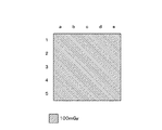
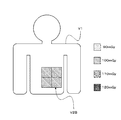
- FIG. 5B shows a conventional method that does not consider the X-ray intensity distribution of the irradiation field.
- the incident dose “100 mGy” is associated with the region “b1”.
- the incident dose “120 mGy” is associated with the region “c3”.
- the average incident dose “100 mGy” is associated with the entire irradiation field.
- the irradiation field can be divided into a plurality of regions, and the incident dose can be calculated for each region.
- the dose data generation unit 43 outputs the generated dose data to the display control unit 32. Further, the dose data generation unit 43 may store the generated dose data in the dose data storage unit 44 in association with information indicating the X-ray examination conditions.
- the dose data storage unit 44 is a storage area for storing dose data. The dose data storage unit 44 is configured to be able to read out dose data corresponding to the conditions by designating the conditions of the X-ray examination.
- the display control unit 32 receives information indicating the position and angle of the C arm 21, the position of the top 24, the position of the X-ray detector 23, the size of the irradiation field, and the state of the X-ray diaphragm 222 from the system control unit 10. receive.
- the display control unit 32 calculates an X-ray incident position and an irradiation field width for a patient modeled on the basis of these pieces of information (hereinafter referred to as “patient model”).
- patient model a patient model
- the display control unit 32 receives from the dose data generation unit 43 dose data in which the incident dose is calculated for each region based on the distribution data.
- the display control unit 32 causes the dose information display unit 331 to display the incident dose on the irradiation surface on the patient model so that it can be identified in units of this area (for example, color-coded according to the incident dose).
- the dose data may be calculated as an integrated dose in real time during the examination and displayed on the dose information display unit 331 sequentially.
- FIG. 6A shows a case where the incident dose of each region is displayed in an identifiable manner on the patient model as an example of a display mode of information indicating the incident dose.
- the display control unit 32 may extract dose data corresponding to information received from the system control unit 10 from the dose data storage unit 44 and display the dose data on the dose information display unit 331. By operating in this way, it is possible to collect dose data in advance and display it on the dose information display unit 331 at a later date for use in diagnosis.
- the dose data generation unit 43 may receive image data from the image data generation unit 31 and store the image data and the generated dose data in the dose data storage unit 44 in association with each other.
- the display control unit 32 reads the image data and the dose data from the dose data storage unit 44 and causes the dose information display unit 331 to display the X-ray image and the incident dose based on the image data and the dose data.
- image data and dose data are stored in association with each other. For example, X-ray images are taken and dose data are generated in advance, and later, X-ray images and incident doses are obtained. Can be operated in such a manner as to be displayed on the dose information display unit 331.
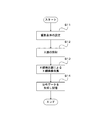
- FIG. 7A is a flowchart showing a series of operations in the preparation stage.
- Step S11 The generation of the distribution data is performed in a state where the X-ray grid of the X-ray detector 23 is removed and the top plate 24 and the compensation filter M1 are not interposed between the X-ray generator 22 and the X-ray detector 23. Further, functions such as image processing are turned off so that the incident X-ray and the output from the X-ray detector 23 are in a proportional relationship.
- the system control unit 10 receives an X-ray inspection condition input by an operator, generates a control signal based on the X-ray inspection condition, and outputs the generated control signal to the X-ray control unit 11 and the mechanism control unit. 13 is output. Further, the system control unit 10 outputs information indicating the X-ray examination conditions to the distribution data generation unit 41.
- Step S12 The mechanism control unit 13 controls the imaging system moving mechanism 14 based on a control signal from the system control unit 10, and operates and rotates the C arm 21 so that the imaging position instructed as an X-ray examination condition is reached.
- the X-ray control unit 11 controls the high voltage generation unit 12 based on a control signal from the system control unit 10, and the X-ray generation unit based on an X-ray irradiation condition instructed as an X-ray examination condition. 22 is irradiated with X-rays.
- the X-ray detector 23 detects the intensity of X-rays emitted from the X-ray generator 22 for each detection element.
- the X-ray detector 23 converts the X-ray intensity detected for each detection element into an electrical signal, and outputs the electrical signal to the distribution data generation unit 41.
- the distribution data generation unit 41 receives image data for each detection element from the X-ray detector 23.
- the distribution data generation unit 41 divides an area where X-rays are detected as image data (that is, an irradiation field) into a plurality of areas in advance, and calculates the SN ratio of the image data for each area. Specifically, for each region, the distribution data generation unit 41 determines the SD value (standard deviation) of the X-ray intensity based on the average X-ray intensity for each detection element and the variance of the X-ray intensity in each detection element. ) Is calculated.
- the distribution data generation unit 41 divides the average of the X-ray intensities by the calculated SD value, so that the ratio of the SD value to the average (output level) of the X-ray intensity in the region is calculated as the SN of the X-ray in the region. Calculate as a ratio.
- the distribution data generation unit 41 measures the relationship between the S / N ratio of X-rays and the incident dose in advance as a characteristic of the X-ray detector 23 and stores it as characteristic data. Based on this characteristic data, the distribution data generation unit 41 converts the SN ratio calculated for each region into an incident dose for each region. The distribution data generation unit 41 converts the incident dose for each region into a ratio for each region (see FIG. 3B) so that the average value is constant.
- the distribution data generation unit 41 receives information from the system control unit 10 indicating the X-ray examination conditions when the distribution data is generated.
- the distribution data generation unit 41 stores the generated distribution data in the distribution data storage unit 42 in association with information indicating the X-ray examination conditions. As described above, the distribution data generation unit 41 generates distribution data for each condition of the X-ray examination, and stores the generated distribution data in the distribution data storage unit 42.
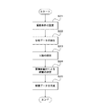
- FIG. 7B is a flowchart showing a series of operations in the inspection stage.
- Step S21 When the condition of the X-ray examination is set by the operator, the system control unit 10 generates a control signal based on this condition and outputs it to the X-ray control unit 11 and the mechanism control unit 13. Further, the system control unit 10 outputs information indicating the conditions of the X-ray examination to the image data generation unit 31 and the dose data generation unit 43.
- the dose data generation unit 43 receives information indicating the X-ray examination conditions from the system control unit 10.
- the dose data generation unit 43 extracts the distribution data associated with this information from the distribution data storage unit 42.
- Step S23 The mechanism control unit 13 controls the imaging system moving mechanism 14 and the top plate moving mechanism 15 based on the control signal from the system control unit 10, and moves the C arm 21 so that the imaging position instructed as a condition for the X-ray inspection is obtained. While operating and rotating, the top plate 24 is moved.
- the X-ray control unit 11 controls the high voltage generation unit 12 based on a control signal from the system control unit 10, and controls the X-ray generation unit 22 based on the X-ray irradiation conditions specified as the X-ray examination conditions. X-rays are irradiated. As a result, X-rays are emitted from the X-ray generator 22 toward the subject P on the top 24.
- Step S24 The area dosimeter 223 detects the X-ray dose irradiated from the X-ray tube 221 and passed through the X-ray diaphragm 222. The area dosimeter 223 converts the detected X-ray dose into electric charges and outputs the charges to the dose data generation unit 43 as an area dose output signal.
- the dose data generation unit 43 receives an area dose output signal from the area dosimeter 223.
- the area dose indicated by this output signal corresponds to the total area dose.
- the dose data generation unit 43 calculates the incident dose for each region based on the total area dose and the dose ratio for each region included in the distribution data.
- the dose data generation unit 43 calculates a region where the X-rays attenuate and the amount of attenuation with use of the compensation filter M1 and transmission through the top plate 24 based on information indicating the conditions of the X-ray examination.
- the dose data generation unit 43 corrects the incident dose calculated for each region based on the calculated attenuation.
- the dose data generation unit 43 calculates an incident dose for each region, and generates dose data associated with the region from which the incident dose is calculated.
- the dose data generation unit 43 outputs the generated dose data to the display control unit 32.
- the display control unit 32 receives information indicating the position and angle of the C arm 21, the position of the top 24, the position of the X-ray detector 23, the size of the irradiation field, and the state of the X-ray diaphragm 222 from the system control unit 10. receive.
- the display control unit 32 calculates the X-ray incident position and the irradiation field width with respect to the patient model based on these pieces of information.
- the display control unit 32 receives from the dose data generation unit 43 dose data in which the incident dose is calculated for each region based on the distribution data.
- the display control unit 32 displays the incident dose on the irradiation surface on the patient model on the dose information display unit 331 so as to be identifiable in units of the regions.
- the irradiation field can be divided into a plurality of regions, and the incident dose can be calculated for each region.
- FIG. 5B is a diagram schematically illustrating an example in which dose data is generated without using distribution data.
- the dose data generation unit 43 recognizes the X-ray intensity distribution in the irradiation field based on the distribution data. Therefore, for example, when distribution data is not used as in the conventional case, it is difficult to recognize each region and calculate an incident dose for each region as shown in FIG. 5B.
- FIG. 6B shows an example of a display mode of information indicating the incident dose in this case.
- the incident dose is managed as X-rays are uniformly irradiated in the irradiation region.
- the X-ray inspection apparatus by using the distribution data, it is possible to divide the irradiation field into a plurality of regions and calculate the incident dose for each region. As a result, for example, as shown in FIGS. 5A and 6A, even when the X-ray intensity distribution varies and the incident dose of X-rays increases locally, this can be detected and managed. It becomes possible.
Landscapes
- Health & Medical Sciences (AREA)
- Life Sciences & Earth Sciences (AREA)
- Medical Informatics (AREA)
- Engineering & Computer Science (AREA)
- Radiology & Medical Imaging (AREA)
- Biomedical Technology (AREA)
- Biophysics (AREA)
- Nuclear Medicine, Radiotherapy & Molecular Imaging (AREA)
- Optics & Photonics (AREA)
- Pathology (AREA)
- Physics & Mathematics (AREA)
- High Energy & Nuclear Physics (AREA)
- Heart & Thoracic Surgery (AREA)
- Molecular Biology (AREA)
- Surgery (AREA)
- Animal Behavior & Ethology (AREA)
- General Health & Medical Sciences (AREA)
- Public Health (AREA)
- Veterinary Medicine (AREA)
- Apparatus For Radiation Diagnosis (AREA)
Priority Applications (2)
| Application Number | Priority Date | Filing Date | Title |
|---|---|---|---|
| US14/119,381 US9538977B2 (en) | 2011-10-07 | 2012-10-02 | X-ray diagnosis apparatus and dose distribution data generation method |
| CN201280035012.7A CN103687542B (zh) | 2011-10-07 | 2012-10-02 | X射线诊断装置及线量管理方法 |
Applications Claiming Priority (2)
| Application Number | Priority Date | Filing Date | Title |
|---|---|---|---|
| JP2011-222639 | 2011-10-07 | ||
| JP2011222639A JP5931394B2 (ja) | 2011-10-07 | 2011-10-07 | X線診断装置及び線量分布データ生成方法 |
Publications (1)
| Publication Number | Publication Date |
|---|---|
| WO2013051550A1 true WO2013051550A1 (ja) | 2013-04-11 |
Family
ID=48043707
Family Applications (1)
| Application Number | Title | Priority Date | Filing Date |
|---|---|---|---|
| PCT/JP2012/075492 Ceased WO2013051550A1 (ja) | 2011-10-07 | 2012-10-02 | X線診断装置及び線量管理方法 |
Country Status (4)
| Country | Link |
|---|---|
| US (1) | US9538977B2 (enExample) |
| JP (1) | JP5931394B2 (enExample) |
| CN (1) | CN103687542B (enExample) |
| WO (1) | WO2013051550A1 (enExample) |
Families Citing this family (6)
| Publication number | Priority date | Publication date | Assignee | Title |
|---|---|---|---|---|
| JP6537797B2 (ja) * | 2014-09-29 | 2019-07-03 | キヤノンメディカルシステムズ株式会社 | 医用画像処理装置及びx線診断装置 |
| JP6415231B2 (ja) * | 2014-10-07 | 2018-10-31 | キヤノン株式会社 | 撮影管理装置、x線撮影システム、情報処理方法及びプログラム |
| JP6523653B2 (ja) | 2014-10-22 | 2019-06-05 | キヤノンメディカルシステムズ株式会社 | 放射線照射装置及び線量管理システム |
| CN106137235A (zh) * | 2016-07-26 | 2016-11-23 | 中国科学院深圳先进技术研究院 | C型臂x光机、控制系统及医学成像系统 |
| JP6874049B2 (ja) * | 2019-04-25 | 2021-05-19 | キヤノンメディカルシステムズ株式会社 | 放射線照射装置及び線量管理システム |
| JP7321131B2 (ja) * | 2020-09-30 | 2023-08-04 | 富士フイルム株式会社 | 制御装置、制御方法、及び制御プログラム |
Citations (7)
| Publication number | Priority date | Publication date | Assignee | Title |
|---|---|---|---|---|
| JP2000065943A (ja) * | 1998-08-07 | 2000-03-03 | General Electric Co <Ge> | 照射線量又は空気カ―マ並びに(照射線量又は空気カ―マ)×(面積)値を予測するための方法及びモデル |
| JP2004069441A (ja) * | 2002-08-05 | 2004-03-04 | Canon Inc | 被曝面積線量計測方法及び装置、吸収面積線量計測方法及び装置、プログラム、記憶媒体、並びに放射線撮影装置 |
| JP2006000223A (ja) * | 2004-06-15 | 2006-01-05 | Canon Inc | X線ct装置 |
| JP2007215918A (ja) * | 2006-02-20 | 2007-08-30 | Shimadzu Corp | X線診断装置 |
| JP2008104704A (ja) * | 2006-10-26 | 2008-05-08 | Shimadzu Corp | 放射線撮像装置 |
| JP2008132147A (ja) * | 2006-11-28 | 2008-06-12 | Toshiba Corp | 被曝線量算出方法及びその装置 |
| JP2008200323A (ja) * | 2007-02-21 | 2008-09-04 | Toshiba Corp | X線装置およびx線画像作成方法 |
Family Cites Families (9)
| Publication number | Priority date | Publication date | Assignee | Title |
|---|---|---|---|---|
| JPS6454341A (en) | 1987-08-26 | 1989-03-01 | Kasei Optonix | Measuring instrument for density and thickness |
| US5317616A (en) * | 1992-03-19 | 1994-05-31 | Wisconsin Alumni Research Foundation | Method and apparatus for radiation therapy |
| US6713773B1 (en) * | 1999-10-07 | 2004-03-30 | Mitec, Inc. | Irradiation system and method |
| US6810107B2 (en) * | 2001-11-02 | 2004-10-26 | Siemens Medical Solutions Usa, Inc. | System and method for measuring beam quality and dosimetry using electronic portal imaging |
| US7356123B2 (en) | 2003-02-11 | 2008-04-08 | Koninklijke Philips Electronics N.V. | X-ray device having a collimator, and method of setting the latter |
| JP2005198762A (ja) | 2004-01-14 | 2005-07-28 | Toshiba Corp | X線診断装置及び照射線量制御方法 |
| US7734010B2 (en) * | 2005-05-13 | 2010-06-08 | Bc Cancer Agency | Method and apparatus for planning and delivering radiation treatment |
| JP5107568B2 (ja) | 2006-12-12 | 2012-12-26 | ジーイー・メディカル・システムズ・グローバル・テクノロジー・カンパニー・エルエルシー | X線ct装置 |
| DE102008050851B4 (de) * | 2008-10-08 | 2010-11-11 | Incoatec Gmbh | Röntgenanalyseinstrument mit verfahrbarem Aperturfenster |
-
2011
- 2011-10-07 JP JP2011222639A patent/JP5931394B2/ja not_active Expired - Fee Related
-
2012
- 2012-10-02 WO PCT/JP2012/075492 patent/WO2013051550A1/ja not_active Ceased
- 2012-10-02 US US14/119,381 patent/US9538977B2/en not_active Expired - Fee Related
- 2012-10-02 CN CN201280035012.7A patent/CN103687542B/zh not_active Expired - Fee Related
Patent Citations (7)
| Publication number | Priority date | Publication date | Assignee | Title |
|---|---|---|---|---|
| JP2000065943A (ja) * | 1998-08-07 | 2000-03-03 | General Electric Co <Ge> | 照射線量又は空気カ―マ並びに(照射線量又は空気カ―マ)×(面積)値を予測するための方法及びモデル |
| JP2004069441A (ja) * | 2002-08-05 | 2004-03-04 | Canon Inc | 被曝面積線量計測方法及び装置、吸収面積線量計測方法及び装置、プログラム、記憶媒体、並びに放射線撮影装置 |
| JP2006000223A (ja) * | 2004-06-15 | 2006-01-05 | Canon Inc | X線ct装置 |
| JP2007215918A (ja) * | 2006-02-20 | 2007-08-30 | Shimadzu Corp | X線診断装置 |
| JP2008104704A (ja) * | 2006-10-26 | 2008-05-08 | Shimadzu Corp | 放射線撮像装置 |
| JP2008132147A (ja) * | 2006-11-28 | 2008-06-12 | Toshiba Corp | 被曝線量算出方法及びその装置 |
| JP2008200323A (ja) * | 2007-02-21 | 2008-09-04 | Toshiba Corp | X線装置およびx線画像作成方法 |
Also Published As
| Publication number | Publication date |
|---|---|
| JP2013081576A (ja) | 2013-05-09 |
| US20140146944A1 (en) | 2014-05-29 |
| CN103687542A (zh) | 2014-03-26 |
| JP5931394B2 (ja) | 2016-06-08 |
| CN103687542B (zh) | 2016-04-27 |
| US9538977B2 (en) | 2017-01-10 |
Similar Documents
| Publication | Publication Date | Title |
|---|---|---|
| CN103201818B (zh) | 用于确定x射线源的x射线发射产量的变化的装置和方法 | |
| JP5931394B2 (ja) | X線診断装置及び線量分布データ生成方法 | |
| JP5136478B2 (ja) | 放射線撮影装置 | |
| JP5343065B2 (ja) | 放射線撮影システム | |
| CN106725567B (zh) | 电子计算机x射线断层扫描仪 | |
| CN102985008B (zh) | X射线摄影装置 | |
| JP2013141574A (ja) | X線撮像装置及びプログラム | |
| JP2012120653A (ja) | 放射線撮影装置、及び放射線撮影システム | |
| JP5188440B2 (ja) | 放射線画像補正方法および放射線画像撮影装置 | |
| CN106028938A (zh) | X射线ct装置以及拍摄方法 | |
| WO2012057278A1 (ja) | 放射線撮影システム及び放射線撮影方法 | |
| JP2021191388A (ja) | 処理装置、処理装置の作動方法、処理装置の作動プログラム | |
| WO2012070661A1 (ja) | 放射線画像検出装置、放射線撮影装置、及び放射線撮影システム | |
| JP6777556B2 (ja) | X線ct装置 | |
| JP2013146490A (ja) | X線診断装置 | |
| JP2004081275A (ja) | X線診断装置およびその制御方法 | |
| JP7207856B2 (ja) | Ct撮影装置 | |
| JP4828854B2 (ja) | X線診断装置およびその管理装置 | |
| JP2016128078A (ja) | X線撮像装置及びプログラム | |
| EP4254018A1 (en) | X-ray diagnostic apparatus and storage medium | |
| JP6183884B2 (ja) | 放射線断層撮影装置および投影データ補正方法並びにプログラム | |
| EP3695786B1 (en) | Tomosynthesis imaging apparatus, method for operating tomosynthesis imaging apparatus, and computer-readable storage medium | |
| JP2014014380A (ja) | 放射線撮影装置、及び放射線撮影システム | |
| CN119326425A (zh) | X射线摄像装置 | |
| JP2025135315A (ja) | Pcct装置とその制御方法 |
Legal Events
| Date | Code | Title | Description |
|---|---|---|---|
| WWE | Wipo information: entry into national phase |
Ref document number: 201280035012.7 Country of ref document: CN |
|
| 121 | Ep: the epo has been informed by wipo that ep was designated in this application |
Ref document number: 12838175 Country of ref document: EP Kind code of ref document: A1 |
|
| WWE | Wipo information: entry into national phase |
Ref document number: 14119381 Country of ref document: US |
|
| NENP | Non-entry into the national phase |
Ref country code: DE |
|
| 122 | Ep: pct application non-entry in european phase |
Ref document number: 12838175 Country of ref document: EP Kind code of ref document: A1 |