WO2013047490A1 - 閉塞開孔方法、閉塞方法および閉塞開孔装置 - Google Patents
閉塞開孔方法、閉塞方法および閉塞開孔装置 Download PDFInfo
- Publication number
- WO2013047490A1 WO2013047490A1 PCT/JP2012/074502 JP2012074502W WO2013047490A1 WO 2013047490 A1 WO2013047490 A1 WO 2013047490A1 JP 2012074502 W JP2012074502 W JP 2012074502W WO 2013047490 A1 WO2013047490 A1 WO 2013047490A1
- Authority
- WO
- WIPO (PCT)
- Prior art keywords
- opening
- plug
- closing
- mud material
- hole
- Prior art date
- Legal status (The legal status is an assumption and is not a legal conclusion. Google has not performed a legal analysis and makes no representation as to the accuracy of the status listed.)
- Ceased
Links
Images


Classifications
-
- C—CHEMISTRY; METALLURGY
- C21—METALLURGY OF IRON
- C21B—MANUFACTURE OF IRON OR STEEL
- C21B7/00—Blast furnaces
- C21B7/12—Opening or sealing the tap holes
Definitions
- the present invention relates to a closing opening method and a closing opening device for closing a tap opening formed on a furnace wall of a blast furnace, and a closing method for closing a tap opening.
- pig iron is taken out by reducing oxygen contained in iron ore.
- the hot metal (molten pig iron) collected in the hot water pool at the bottom of the blast furnace is taken out from a tap outlet provided on the furnace wall beside the hot water pool.
- the taphole is closed by filling and firing a clay-like refractory called mud material.
- a pneumatic or hydraulic opening machine to open and close the plugging material filled in the spout by moving the conical rod back and forth, hitting, and rotating. Is done.
- a mud gun is used to fill mud material into the outlet and baked to close the outlet.
- the opening and closing operations of the tap holes are performed using dedicated devices such as a hole opening machine and a mud gun, respectively.
- the mud material filled in the tap is usually consolidated in a convex state on the inside of the furnace, but the state of the inside of the furnace at the tap and the mud filled Since the shape varies depending on the amount, the position of the most adhering part of the mud material adhering to the inside of the furnace at the outlet is not uniform. For this reason, it is difficult to make a hole determination based on the drilling depth of the tap hole, and the hole determination is difficult.
- the filled mud material may have a gap in its interior, and if the hole detection is performed based on the forward load or rotational load of the conical rod, the forward load or rotational load will be weakened by the gap, and the spout will be opened. There is a risk of misjudging that has penetrated.
- it is required to always keep the closing state of the tap opening constant.
- Patent Document 1 a method described in Patent Document 1 is known as an example of a closing technique for a spout.
- This method is a method in which a mud material is filled into the tap hole, a large-diameter hole is dug to the middle of the mud material during firing, and the large-diameter hole is filled again with the mud material.
- FIG. 1 Another example of the blocking technique is a method described in Patent Document 2.
- a mud material is filled in the spout and the mud material is fired by furnace heat, and then drilled with an opening bit leaving a thickness necessary to prevent the hot metal from being ejected.
- An appropriate amount of fluid refractory is injected into the hole.
- the fluidized refractory is filled in the gap between the inside of the opening and the outside of the refractory cylindrical body at the same time as inserting the previously formed and solidified refractory cylindrical body into the opening.
- Patent Document 3 a solid mud material formed in a columnar shape with a cross-sectional shape slightly larger than the cross-sectional shape of the tap bar around the core bar is driven into the tap bar and closed.
- the present invention provides a closing opening method and closing opening device capable of easily closing a closing spout while closing the spout opening, and a closing method for closing the spitting opening. Objective.
- a closed hole opening method is a closed hole opening method for closing a tap hole formed on a furnace wall of a blast furnace and opening the closed tap hole.
- a plugging step formed by pushing a plug formed in a substantially rod shape into the tap hole, filling the plug material and firing the mud material to block the tap port; and the plug plug and the fired mud material
- An opening step of excavating to form the tap hole, and the closing plug has a portion formed so as to be softer than the fired product of the mud material so as to continue over its entire length.
- the blocking plug may include a tubular member and a filling member disposed in a pipe line of the tubular member.
- the filling member may be a refractory softer than the fired product of the mud material, and the filling member may be excavated during the opening step.
- the filling member may be made of a material that becomes a refractory softer than the fired product of the mud material by being fired, and the filling member may be excavated during the opening step.
- the filling member may be disposed only on the other end side of the tubular member from a position separated from the one end of the tubular member by a certain distance. (6) It is good for the said obstruction
- occlusion stopper to be the length substantially equal to the length of the said spout opening.
- a closed hole opening device is a closed hole opening device that closes a tap opening formed in a furnace wall of a blast furnace and opens the closed tap opening, wherein a mud material is A casing having an internal space to be accommodated and formed with an injection opening and a through hole communicating with the internal space, a pressure generating portion for applying pressure to the mud material accommodated in the internal space, and a substantially rod shape
- An attachment / detachment portion detachably connected to the formed closure plug, and the closure plug connected to the attachment / detachment portion project from the injection opening to the outside of the casing through the through hole and the internal space.
- a drive unit for moving, and an opening machine part for excavating the plugged plug and the baked mud material, which are closed after the closing of the taping port, Is a fired product of the mud material.
- a portion remote is soft formed, it has to be continuous over the entire length of its own.
- the opening machine portion is disposed outside the casing, and is configured to open the opening rod connected to the attachment / detachment portion detachably and the opening rod connected to the attachment / detachment portion. It is good to have the rotation drive part rotated about the axis line of a hole rod.
- a guide tube provided in the internal space, wherein one opening is disposed in the injection opening in a state separated from the opening edge of the injection opening, and the other opening communicates with the through hole. It is preferable that the closure plug is inserted into the guide tube and guided for movement.
- a closing method is a closing method for closing a tap opening formed in a furnace wall of a blast furnace, and a mud material and a closing plug formed in a substantially rod shape are pushed into the tap opening.
- the closing plug may include a tubular member and a filling member disposed in a pipe line of the tubular member.
- the filling member may be a refractory softer than the fired product of the mud material.
- the filling member may be disposed inside a position spaced apart from the opening end of the tubular member facing the outside of the blast furnace by a certain distance.
- the closing plug may have a length substantially equal to the length of the tap hole.
- the closure plug has a portion formed so as to be softer than the fired product of the mud material so as to continue over its entire length. The force required for the hole is reduced, and the tap hole can be easily opened.
- the tap hole can be easily opened.
- the member for excavating the filling member can be easily positioned on one end side of the tubular member.
- C Since the length of excavation at the time of opening is almost equal to the length of the blocking plug, the tap hole can be opened more easily.
- D The operation of closing the tap opening and the operation of opening the closed tap opening can be performed with a single device.
- E The mud material is prevented from adhering to the closing plug in the casing.
- occlusion stopper can be easily inserted in an outlet.
- FIG. 1 It is a figure which shows the obstruction
- the closing hole opening device 1 opens a closing mode for closing the tap outlet W2 formed in the furnace wall W1 of the blast furnace W, and opens the closing tap W2 shown in FIG.
- the state of the apparatus can be switched to a hole opening mode.
- the block opening device 1 includes a casing 10 in which an internal space 11 in which the mud material 100 can be accommodated and a hydraulic pressure generating unit that applies pressure to the mud material 100 accommodated in the internal space 11. (Pressure generating part) 20, Opening rod 30 for opening tap hole W2 (see FIG. 2), removably connected to the base end of blocking plug 110 and the like and rotating blocking plug 110 and the like An attachment / detachment / rotation unit (attachment / removal unit, rotation drive unit) 35 to be moved and an advance / retreat drive unit 45 to move the attachment / detachment / rotation unit 35 are provided.
- the aperture rod 30 and the attachment / detachment / rotation unit 35 constitute an aperture machine unit.
- the casing 10 includes a nozzle 12 in which an injection opening 12a is formed, and a substantially cylindrical barrel 13 that is disposed on the proximal end side of the nozzle 12 and in which a through hole 13a is formed.
- the injection opening 12a and the through hole 13a communicate with the internal space 11 formed when the nozzle 12 and the barrel 13 are connected.
- the hydraulic pressure generator 20 is attached to the base end side of the casing 10.
- the hydraulic pressure generator 20 includes a hydraulic cylinder 21 to which oil is supplied from an oil supply source (not shown), and a piston 22 that is moved in the front-rear direction by the hydraulic cylinder 21.
- the hydraulic cylinder 21 is provided with an inlet (not shown) and an outlet that adjust the amount of oil in the hydraulic cylinder 21.
- a seal member (not shown) is provided between the outer peripheral surface of the piston 22 and the inner peripheral surface of the hydraulic cylinder 21 to keep the space between the piston 22 and the hydraulic cylinder 21 watertight. Even when the piston 22 is moved to the distal end side by the hydraulic cylinder 21, the injection opening 12a and the through hole 13a are set in front of the piston 22. In the present embodiment, since the piston 22 does not block the injection opening 12a and the through hole 13a, a hole for allowing the blocking plug 110 and the mud material 100 to pass through the piston 22 and the hydraulic cylinder 21 is not formed.
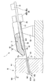
- the opening rod 30 is formed in a long and narrow bar shape as shown in FIG.
- a bit 31 for excavating the furnace wall W1 and the like is provided at the tip of the aperture rod 30.
- a female thread portion 32 as shown in FIG. 3 is formed at the proximal end of the aperture rod 30.
- the aperture rod 30 is arranged and used outside the casing 10.
- the closing plug 110 used in the closing hole opening device 1 of the present embodiment is formed into a substantially rod shape by a fired refractory softer than a fired product of the mud material 100 (fired mud material 100A described later). Is formed.
- the length of the blocking plug 110 is set to be approximately equal to the length of the tap hole W2.
- the closing plug 110 is formed of a refractory material obtained by firing a mud material made of alumina, wax, silicon carbide, refractory clay, or the like.
- the content of the binder (tar, resin) in the mud material may be increased.
- a female screw portion such as the female screw portion 32 of the aperture rod 30 described above is formed at the proximal end of the closing plug 110.
- the attachment / detachment / rotation unit 35 includes an attachment / detachment / rotation mechanism 36 and an attachment / detachment adapter 37 connected to the attachment / detachment / rotation mechanism 36.
- the attachment / detachment / rotation mechanism 36 includes a male screw portion 38 shown in FIG. 3 and a rotation drive motor (not shown).
- the aperture rod 30 can be connected to the attachment / detachment / rotation mechanism 36 by screwing the female thread portion 32 of the aperture rod 30 into the male thread portion 38.
- the rotation drive motor rotates the male screw portion 38 around the axis C1 of the male screw portion 38. Thereby, the aperture rod 30 connected to the external thread part 38 of the attachment / detachment / rotation mechanism 36 can rotate around its own axis.
- the detachable adapter 37 has a gear box (not shown) and a connecting shaft 39.
- the gear box is engaged with the male screw portion 38 of the attachment / detachment / rotation mechanism 36, and the connecting shaft 39 can be rotated around the axis C2.
- a male screw portion (not shown) that is screwed with the female screw portion of the closing plug 110 is formed at the tip of the connecting shaft 39.
- the axis C2 of the connecting shaft 39 and the axis C1 of the male screw portion 38 are set substantially parallel. In this example, the axis C1 is disposed below the injection opening 12a and the through hole 13a.
- the advance / retreat drive unit 45 includes an advance / retreat drive motor 45a installed on the guide rail 51, and an advance / retreat drive unit main body 45b connected to the lower part of the guide rail 51 so as to be slidable in the direction of the axis C2.
- the advance / retreat drive section main body 45b can be advanced and retracted along the guide rail 51 in the direction of the axis C2.
- the obturator plug 110 is connected to the male thread portion of the connecting shaft 39, and the obturator plug 110 is moved to the distal end side by the advance / retreat drive unit 45, whereby the obturator plug 110 is moved forward from the injection opening 12a through the through hole 13a and the internal space 11. Can be protruded.
- the position adjusting device 52 is disposed on the floor surface W3 and can adjust the position of the casing 10 in the front-rear direction and the vertical direction with respect to the floor surface W3.
- a plug member 53 that closes the through hole 13a may be used.
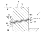
- FIG. 1 As shown in FIG. 1, as shown in FIG. 1, a closing process is performed in which the tap wall W ⁇ b> 2 is formed in the furnace wall W ⁇ b> 1 and the tap opening W ⁇ b> 2 is closed with the closing hole opening device 1 in the closing mode. I will explain from what to do. In this state, hot hot metal W5 in the blast furnace W flows out to the furnace outer side D1.
- the blocking plug 110 is inserted through the through hole 13a of the casing 10 (blocking plug placement step). Specifically, the advance / retreat drive unit main body 45b of the advance / retreat drive unit 45 is moved to the proximal end side on the guide rail 51, and the attachment / detachment adapter 37 is connected to the attachment / detachment / rotation mechanism 36. The obturator plug 110 is connected to. At this time, the closing plug 110 is held in front of the connecting shaft 39, and the connecting shaft 39 is rotated around the axis C ⁇ b> 2 with respect to the closing plug 110 by the attaching / detaching / rotating mechanism 36.
- occlusion stopper 110 and the external thread part of the connection shaft 39 can be screwed together, and the obstruction
- the closing stopper 110 is moved to the distal end side by the advancing / retreating drive unit 45 and adjusted so that the distal end of the closing stopper 110 passes through the through-hole 13a and substantially coincides with the injection opening 12a.
- the tap hole W2 of the furnace wall W1 and the injection opening 12a of the casing 10 are communicated (communication arrangement step). This is performed by adjusting the position of the casing 10 in the front-rear direction and the vertical direction by the position adjusting device 52. Subsequently, as shown in FIG. 4, the oil pressure generating unit 20 pushes the mud material 100 into the outlet port W2 through the injection opening 12a and fills the outlet port W2 with the mud material 100 (a mud material pressing step).
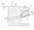
- the closing plug 110 is pushed into the outlet W2 through the injection opening 12a of the casing 10 (blocking plug pushing step). Due to the blocking plug 110 pushed into the tap outlet W2, the mud material 100 pushed out from the tap outlet W2 rises to a convex state at the furnace inner side D2, and forms a protective mud 101.
- the protective mud 101 protects the furnace wall W1 from being eroded by the molten iron W5 flowing out from the outlet W2.
- the casing 10 is kept in contact with the tap hole W2 for a certain period of time, and then the casing 10 is moved to the base end side by the position adjusting device 52 to separate the casing 10 from the tap hole W2 (firing step). .
- the mud material 100 is baked by the heat of the hot metal W5, resulting in a baked mud material 100A shown in FIG. This is the end of the closing process.
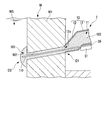
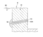
- the casing 10 is moved upward by the position adjusting device 52, and the bit 31 of the aperture rod 30 is brought into contact with the closing plug 110 that closes the spout W2.
- the obstruction plug 110 and the obstruction plug 110 are moved to the furnace inner side D2.
- a certain fired mud material 100A is excavated to form a spout W2. This completes the hole opening step.
- the blocking plug 110 is formed of a refractory material softer than the fired mud material 100A.
- the fired mud material 100A is harder than the closing plug 110 and is less likely to be eroded by the hot metal W5 or the like, so that it is possible to prevent the spout W2 from being eroded by the hot metal W5 and becoming larger.
- the length of the blocking plug 110 is set to be approximately equal to the length of the tap hole W2. Accordingly, the length of excavation in the opening step is almost equal to the length of the blocking plug 110, and a soft member is excavated in the opening step, so that the tap hole W2 can be opened more easily. .
- the blocking hole opening device 1 includes the hole rod 30 and the attachment / detachment / rotation unit 35, by switching between the blocking mode and the hole opening mode, both the blocking step and the hole opening step are performed with one device. Can do. Since the opening rod 30 is arranged outside the casing 10 in the opening step, even if the opening rod 30 is bent by the heat of the hot metal W5, it is possible to prevent the obstruction opening device 1 from being obstructed.
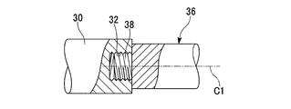
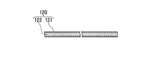
- the closing plug 120 used in the closing device 1 of this embodiment includes a pipe (tubular member) 121 whose outer diameter is set smaller than the inner diameter of the spout W2, and a pipe of the pipe 121. And a filling member 122 disposed in the path.
- a material for forming the pipe 121 for example, a metal such as steel can be used.
- the filling member 122 is formed of the same material as the above-described closing plug 110.
- a female screw portion having the same shape as the female screw portion of the blocking plug 110 is formed at the proximal end of the blocking plug 120.
- the block opening method of this embodiment performed using the block plug 120 and the block opening apparatus 1 configured as described above will be described. Since the closing process is the same as the process of the first embodiment performed using the closing plug 110, description thereof is omitted.
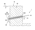
- the opening step as shown in FIG. 8, the bit 31 of the opening rod 30 is brought into contact with the filling member 122 of the closing plug 120 that closes the spout W2. Then, the filling member 122 of the closing plug 120 and the firing mud material 100A located in the furnace inner side D2 from the filling member 122 are excavated to form the spout W2.
- the tap opening W2 can be easily opened by excavating the filling member 122 softer than the fired mud material 100A. Can do.
- a portion of the closing plug 120 that is softer than the fired mud material 100 ⁇ / b> A is formed so as to be continuous over the entire length of the closing plug 120.
- the tap hole W2 can be easily opened by excavating the softly formed portion with the hole rod 30 over the entire length of the closing plug 120.
- the whole closure plug 110 may be formed softly, and a part of outer periphery of the closure plug may be formed softly over the full length.
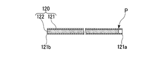
- a blocking plug 130 shown in FIG. 9 may be used instead of the blocking plug 120.
- the filling member 122 is arranged only on the other end 121 b side of the pipe 121 from the position P at a certain distance from the one end 121 a of the pipe 121. This fixed distance is appropriately set according to the size of the bit 31 in the closing device 1.
- a female screw portion having the same shape as the female screw portion of the closing plug 110 is preferably formed on the inner peripheral surface of the pipe 121 on the one end 121a side.
- the closing process of the closing hole opening method performed using the closing plug 130 of the modified example configured as described above is the same as the closing process of the present embodiment.
- the opening process is as follows. As shown in FIG. 10, the bit 31 of the closing hole device 1 is inserted into one end 121 a of the pipe 121 of the closing plug 130, and the opening rod 30 is rotated around its axis by the attaching / detaching / rotating mechanism 36. As a result, the filling member 122 and the firing mud material 100A located in the furnace inner side D2 from the filling member 122 are excavated to form the spout W2.
- the tip of the opening rod 30 until the recess is formed in the filling member 122 on the furnace outer side D2. Therefore, the operator restrains the position of the tip of the aperture rod 30 using a metal rod or the like.
- the closure plug 130 of this modification the tip of the aperture rod 30 can be easily positioned with respect to the closure plug 130, and rotational blurring of the aperture rod 30 can be suppressed. Thereby, the spout W2 can be formed in a short time.
- the closing plug 110 and the filling member 122 of the closing plug 120 are formed of a fired refractory softer than the fired mud material 100A.
- these may be formed of a material that becomes a refractory softer than the fired mud material 100A when fired.
- this material the above-mentioned alumina, wax, silicon carbide, refractory clay, and a mixture thereof can be used.
- the closing hole device 2 may include a guide tube 61 provided in the internal space 11 of the casing 10.
- One end 61 a of the guide tube 61 is disposed in a state of being separated from an opening edge portion that forms the injection opening 12 a in the injection opening 12 a of the casing 10.
- the guide tube 61 is disposed so that the opening on the other end 61b side communicates with the through hole 13a.
- the inner diameter of the guide tube 61 is set so that the closing plug 110 can be inserted.
- the hole-opening machine part is configured by the hole-forming rod 30 and the attachment / detachment / rotation part 35 and is configured integrally with the closing hole-opening device 1.
- the obturator opening device may not be provided with an opening machine part, and a known conical rod or the like may be used as the opening machine part.
- the length of the closing plug is set to be approximately equal to the length of the tap hole W2.
- the length of the obturator plug is not limited, and can be set as appropriate, for example, shorter than the length of the spout W2.
- the closure port W2 is blocked only by the mud material 100 without pushing the closure plug 110 into the exit port W2 in the closing step.
- the spout W2 can be closed by the same method as in FIG. That is, the closing device 1 of the present invention switches between a method of closing the spout W2 using the mud material 100 and the closing plug 110 and a method of closing the spout W2 using only the mud material 100. Can be used.
- the present invention relates to a closing opening method for closing an opening formed in a furnace wall of a blast furnace and opening the closed opening, which includes a mud material and a plug formed in a substantially rod shape.
- the mud material is baked to close the tap port, and the closing plug and the fired mud material are excavated to form the tap port
- the closing plug has a portion formed so as to be softer than the fired product of the mud material so as to continue over its entire length.
- the closure plug has a portion formed so as to be softer than the fired product of the mud material so as to continue over its entire length. The force required for the hole is reduced, and the tap hole can be easily opened.
Landscapes
- Engineering & Computer Science (AREA)
- Chemical & Material Sciences (AREA)
- Manufacturing & Machinery (AREA)
- Materials Engineering (AREA)
- Metallurgy (AREA)
- Organic Chemistry (AREA)
- Furnace Charging Or Discharging (AREA)
- Blast Furnaces (AREA)
Priority Applications (4)
| Application Number | Priority Date | Filing Date | Title |
|---|---|---|---|
| KR1020147008935A KR101593345B1 (ko) | 2011-09-27 | 2012-09-25 | 폐색 개공 방법, 폐색 방법 및 폐색 개공 장치 |
| BR112014007046-6A BR112014007046B1 (pt) | 2011-09-27 | 2012-09-25 | Método de bloqueio/abertura para furo de corrida e aparelho de bloqueio/abertura |
| CN201280046784.0A CN103890198B (zh) | 2011-09-27 | 2012-09-25 | 闭塞开孔方法、闭塞方法以及闭塞开孔装置 |
| IN2846DEN2014 IN2014DN02846A (enExample) | 2011-09-27 | 2012-09-25 |
Applications Claiming Priority (2)
| Application Number | Priority Date | Filing Date | Title |
|---|---|---|---|
| JP2011-210737 | 2011-09-27 | ||
| JP2011210737A JP5785838B2 (ja) | 2011-09-27 | 2011-09-27 | 閉塞開孔方法および閉塞開孔装置 |
Publications (1)
| Publication Number | Publication Date |
|---|---|
| WO2013047490A1 true WO2013047490A1 (ja) | 2013-04-04 |
Family
ID=47995522
Family Applications (1)
| Application Number | Title | Priority Date | Filing Date |
|---|---|---|---|
| PCT/JP2012/074502 Ceased WO2013047490A1 (ja) | 2011-09-27 | 2012-09-25 | 閉塞開孔方法、閉塞方法および閉塞開孔装置 |
Country Status (7)
| Country | Link |
|---|---|
| JP (1) | JP5785838B2 (enExample) |
| KR (1) | KR101593345B1 (enExample) |
| CN (1) | CN103890198B (enExample) |
| BR (1) | BR112014007046B1 (enExample) |
| IN (1) | IN2014DN02846A (enExample) |
| TW (1) | TWI493044B (enExample) |
| WO (1) | WO2013047490A1 (enExample) |
Families Citing this family (6)
| Publication number | Priority date | Publication date | Assignee | Title |
|---|---|---|---|---|
| CN105319579B (zh) * | 2014-06-26 | 2017-11-03 | 中石化石油工程地球物理有限公司胜利分公司 | 泥枪震源枪钻一体钻进式下枪机构 |
| CN104141021B (zh) * | 2014-08-28 | 2015-11-11 | 中冶南方工程技术有限公司 | 一种高炉开铁口的方法及高炉开铁口设备系统 |
| EP3938548B1 (de) * | 2019-03-13 | 2023-05-03 | Tmt - Tapping Measuring Technology Sàrl | Stichlochstopfkanone |
| JP7166469B2 (ja) * | 2019-03-13 | 2022-11-07 | ティエムティ - タッピング メジャーリング テクノロジー エスエイアールエル | タップ穴プラグガン |
| TWI779501B (zh) * | 2021-02-24 | 2022-10-01 | 中國鋼鐵股份有限公司 | 導引裝置、導引系統及其操作方法 |
| JP7662043B2 (ja) * | 2022-05-19 | 2025-04-15 | Jfeスチール株式会社 | 高炉操業方法 |
Citations (4)
| Publication number | Priority date | Publication date | Assignee | Title |
|---|---|---|---|---|
| JPS63161105A (ja) * | 1986-12-24 | 1988-07-04 | Kawasaki Refract Co Ltd | 高炉出銑孔の閉塞方法 |
| JPS63166919A (ja) * | 1986-12-27 | 1988-07-11 | Kawasaki Refract Co Ltd | マツド材の供給方法 |
| JPH01225712A (ja) * | 1988-02-03 | 1989-09-08 | Dango & Dienenthal Kg | 炉の出銑口を閉寒する方法およびこの方法を実施するためのマッド・ガン |
| JPH1046218A (ja) * | 1996-08-05 | 1998-02-17 | Matsuda Astec Kk | 残銑抜き孔の開閉装置 |
Family Cites Families (9)
| Publication number | Priority date | Publication date | Assignee | Title |
|---|---|---|---|---|
| JPS6126709A (ja) * | 1984-07-17 | 1986-02-06 | Nippon Steel Corp | 出銑孔の閉塞方法 |
| JPH01127612A (ja) | 1987-11-09 | 1989-05-19 | Kawasaki Steel Corp | 高炉出銑口の閉塞方法 |
| DE3803625A1 (de) * | 1988-02-06 | 1989-08-17 | Dango & Dienenthal Maschbau | Verfahren und vorrichtung zum oeffnen des stichlochs von oefen |
| EP0574729B1 (fr) * | 1992-06-17 | 1998-12-02 | Paul Wurth S.A. | Machine de perçage d'un trou de coulée d'un four à cuve |
| LU88453A1 (fr) * | 1994-01-17 | 1995-09-01 | Wurth Paul Sa | Dispositif de bouchage du trou de coulée |
| JPH0853703A (ja) * | 1994-08-10 | 1996-02-27 | Nippon Steel Corp | 高炉出銑口形成方法 |
| KR200168296Y1 (ko) * | 1999-08-06 | 2000-02-15 | 삼성전자주식회사 | 인쇄회로기판 |
| JP2002371308A (ja) * | 2001-06-13 | 2002-12-26 | Sumitomo Metal Ind Ltd | 高炉出銑口装置とその運転制御方法 |
| JP2003247011A (ja) * | 2002-02-20 | 2003-09-05 | Nippon Steel Corp | 冶金炉用出湯口の開閉方法および開閉装置 |
-
2011
- 2011-09-27 JP JP2011210737A patent/JP5785838B2/ja not_active Expired - Fee Related
-
2012
- 2012-09-25 BR BR112014007046-6A patent/BR112014007046B1/pt active IP Right Grant
- 2012-09-25 KR KR1020147008935A patent/KR101593345B1/ko active Active
- 2012-09-25 IN IN2846DEN2014 patent/IN2014DN02846A/en unknown
- 2012-09-25 CN CN201280046784.0A patent/CN103890198B/zh active Active
- 2012-09-25 WO PCT/JP2012/074502 patent/WO2013047490A1/ja not_active Ceased
- 2012-09-27 TW TW101135615A patent/TWI493044B/zh not_active IP Right Cessation
Patent Citations (4)
| Publication number | Priority date | Publication date | Assignee | Title |
|---|---|---|---|---|
| JPS63161105A (ja) * | 1986-12-24 | 1988-07-04 | Kawasaki Refract Co Ltd | 高炉出銑孔の閉塞方法 |
| JPS63166919A (ja) * | 1986-12-27 | 1988-07-11 | Kawasaki Refract Co Ltd | マツド材の供給方法 |
| JPH01225712A (ja) * | 1988-02-03 | 1989-09-08 | Dango & Dienenthal Kg | 炉の出銑口を閉寒する方法およびこの方法を実施するためのマッド・ガン |
| JPH1046218A (ja) * | 1996-08-05 | 1998-02-17 | Matsuda Astec Kk | 残銑抜き孔の開閉装置 |
Also Published As
| Publication number | Publication date |
|---|---|
| IN2014DN02846A (enExample) | 2015-05-15 |
| KR101593345B1 (ko) | 2016-02-11 |
| JP5785838B2 (ja) | 2015-09-30 |
| KR20140066215A (ko) | 2014-05-30 |
| BR112014007046A2 (pt) | 2017-04-11 |
| CN103890198A (zh) | 2014-06-25 |
| TWI493044B (zh) | 2015-07-21 |
| TW201326407A (zh) | 2013-07-01 |
| JP2013072102A (ja) | 2013-04-22 |
| BR112014007046B1 (pt) | 2019-02-19 |
| CN103890198B (zh) | 2016-01-13 |
Similar Documents
| Publication | Publication Date | Title |
|---|---|---|
| JP5785838B2 (ja) | 閉塞開孔方法および閉塞開孔装置 | |
| US4671703A (en) | Apparatus for driving pipes through the ground | |
| CA2608050A1 (en) | Flow nozzle assembly | |
| US9022697B2 (en) | Method, system and rock drilling apparatus for installing a pipe in drilled holes in rock drilling | |
| ITTO20090593A1 (it) | Macchina per la perforazione del terreno. | |
| US4960379A (en) | Process and apparatus for opening furnace tapholes | |
| JP5771433B2 (ja) | 出銑口の閉塞構造および出銑口の閉塞方法 | |
| KR20130034000A (ko) | 해머 장치의 충격 기구 그리고 출강구를 개방하기 위한 방법 | |
| JPH02240321A (ja) | 現場打パイルを形成する装置 | |
| JP2017150226A (ja) | 削孔用口元装置、削孔装置、及び削孔方法 | |
| JP6895929B2 (ja) | 削孔器具、棒状部材および削孔方法 | |
| CN109026095B (zh) | 锚杆孔施工工艺 | |
| EP0182974B1 (de) | Verfahren und Vorrichtung zum Öffnen und Schliessen eines Stichloches an Öfen | |
| JPH01225712A (ja) | 炉の出銑口を閉寒する方法およびこの方法を実施するためのマッド・ガン | |
| JP5294134B2 (ja) | タップホルダー | |
| JP7173684B2 (ja) | ロックボルト構造の構築方法 | |
| JP2013072103A (ja) | 出銑口の閉塞方法 | |
| KR200224581Y1 (ko) | 고로의 출선구 노저부 승온 억제장치 | |
| US298251A (en) | Chaeles a | |
| JP2012219331A (ja) | 開孔閉塞装置 | |
| KR20110133849A (ko) | 고로 출선구용 개폐장치 | |
| KR101203643B1 (ko) | 개공기용 선단걸고리의 핀 제거장치 | |
| CN118996975B (zh) | 一种道路桥梁施工裂缝填充装置 | |
| EP1233077A1 (en) | System for repairing blast furnace taphole facings | |
| JPS58199807A (ja) | 高炉出銑口の閉塞方法 |
Legal Events
| Date | Code | Title | Description |
|---|---|---|---|
| 121 | Ep: the epo has been informed by wipo that ep was designated in this application |
Ref document number: 12835940 Country of ref document: EP Kind code of ref document: A1 |
|
| NENP | Non-entry into the national phase |
Ref country code: DE |
|
| ENP | Entry into the national phase |
Ref document number: 20147008935 Country of ref document: KR Kind code of ref document: A |
|
| REG | Reference to national code |
Ref country code: BR Ref legal event code: B01A Ref document number: 112014007046 Country of ref document: BR |
|
| 122 | Ep: pct application non-entry in european phase |
Ref document number: 12835940 Country of ref document: EP Kind code of ref document: A1 |
|
| ENP | Entry into the national phase |
Ref document number: 112014007046 Country of ref document: BR Kind code of ref document: A2 Effective date: 20140324 |