WO2013042640A1 - 積層電池およびこれを用いた組電池 - Google Patents
積層電池およびこれを用いた組電池 Download PDFInfo
- Publication number
- WO2013042640A1 WO2013042640A1 PCT/JP2012/073749 JP2012073749W WO2013042640A1 WO 2013042640 A1 WO2013042640 A1 WO 2013042640A1 JP 2012073749 W JP2012073749 W JP 2012073749W WO 2013042640 A1 WO2013042640 A1 WO 2013042640A1
- Authority
- WO
- WIPO (PCT)
- Prior art keywords
- electrode
- battery
- current collector
- exterior body
- negative electrode
- Prior art date
- Legal status (The legal status is an assumption and is not a legal conclusion. Google has not performed a legal analysis and makes no representation as to the accuracy of the status listed.)
- Ceased
Links
Images


Classifications
-
- H—ELECTRICITY
- H01—ELECTRIC ELEMENTS
- H01M—PROCESSES OR MEANS, e.g. BATTERIES, FOR THE DIRECT CONVERSION OF CHEMICAL ENERGY INTO ELECTRICAL ENERGY
- H01M10/00—Secondary cells; Manufacture thereof
- H01M10/04—Construction or manufacture in general
- H01M10/045—Cells or batteries with folded plate-like electrodes
-
- H—ELECTRICITY
- H01—ELECTRIC ELEMENTS
- H01M—PROCESSES OR MEANS, e.g. BATTERIES, FOR THE DIRECT CONVERSION OF CHEMICAL ENERGY INTO ELECTRICAL ENERGY
- H01M50/00—Constructional details or processes of manufacture of the non-active parts of electrochemical cells other than fuel cells, e.g. hybrid cells
- H01M50/50—Current conducting connections for cells or batteries
- H01M50/531—Electrode connections inside a battery casing
- H01M50/54—Connection of several leads or tabs of plate-like electrode stacks, e.g. electrode pole straps or bridges
-
- H—ELECTRICITY
- H01—ELECTRIC ELEMENTS
- H01M—PROCESSES OR MEANS, e.g. BATTERIES, FOR THE DIRECT CONVERSION OF CHEMICAL ENERGY INTO ELECTRICAL ENERGY
- H01M10/00—Secondary cells; Manufacture thereof
- H01M10/60—Heating or cooling; Temperature control
- H01M10/61—Types of temperature control
- H01M10/613—Cooling or keeping cold
-
- H—ELECTRICITY
- H01—ELECTRIC ELEMENTS
- H01M—PROCESSES OR MEANS, e.g. BATTERIES, FOR THE DIRECT CONVERSION OF CHEMICAL ENERGY INTO ELECTRICAL ENERGY
- H01M10/00—Secondary cells; Manufacture thereof
- H01M10/60—Heating or cooling; Temperature control
- H01M10/64—Heating or cooling; Temperature control characterised by the shape of the cells
- H01M10/647—Prismatic or flat cells, e.g. pouch cells
-
- H—ELECTRICITY
- H01—ELECTRIC ELEMENTS
- H01M—PROCESSES OR MEANS, e.g. BATTERIES, FOR THE DIRECT CONVERSION OF CHEMICAL ENERGY INTO ELECTRICAL ENERGY
- H01M50/00—Constructional details or processes of manufacture of the non-active parts of electrochemical cells other than fuel cells, e.g. hybrid cells
- H01M50/50—Current conducting connections for cells or batteries
- H01M50/502—Interconnectors for connecting terminals of adjacent batteries; Interconnectors for connecting cells outside a battery casing
- H01M50/503—Interconnectors for connecting terminals of adjacent batteries; Interconnectors for connecting cells outside a battery casing characterised by the shape of the interconnectors
-
- H—ELECTRICITY
- H01—ELECTRIC ELEMENTS
- H01M—PROCESSES OR MEANS, e.g. BATTERIES, FOR THE DIRECT CONVERSION OF CHEMICAL ENERGY INTO ELECTRICAL ENERGY
- H01M50/00—Constructional details or processes of manufacture of the non-active parts of electrochemical cells other than fuel cells, e.g. hybrid cells
- H01M50/50—Current conducting connections for cells or batteries
- H01M50/502—Interconnectors for connecting terminals of adjacent batteries; Interconnectors for connecting cells outside a battery casing
- H01M50/509—Interconnectors for connecting terminals of adjacent batteries; Interconnectors for connecting cells outside a battery casing characterised by the type of connection, e.g. mixed connections
- H01M50/51—Connection only in series
-
- H—ELECTRICITY
- H01—ELECTRIC ELEMENTS
- H01M—PROCESSES OR MEANS, e.g. BATTERIES, FOR THE DIRECT CONVERSION OF CHEMICAL ENERGY INTO ELECTRICAL ENERGY
- H01M50/00—Constructional details or processes of manufacture of the non-active parts of electrochemical cells other than fuel cells, e.g. hybrid cells
- H01M50/50—Current conducting connections for cells or batteries
- H01M50/502—Interconnectors for connecting terminals of adjacent batteries; Interconnectors for connecting cells outside a battery casing
- H01M50/521—Interconnectors for connecting terminals of adjacent batteries; Interconnectors for connecting cells outside a battery casing characterised by the material
- H01M50/522—Inorganic material
-
- Y—GENERAL TAGGING OF NEW TECHNOLOGICAL DEVELOPMENTS; GENERAL TAGGING OF CROSS-SECTIONAL TECHNOLOGIES SPANNING OVER SEVERAL SECTIONS OF THE IPC; TECHNICAL SUBJECTS COVERED BY FORMER USPC CROSS-REFERENCE ART COLLECTIONS [XRACs] AND DIGESTS
- Y02—TECHNOLOGIES OR APPLICATIONS FOR MITIGATION OR ADAPTATION AGAINST CLIMATE CHANGE
- Y02E—REDUCTION OF GREENHOUSE GAS [GHG] EMISSIONS, RELATED TO ENERGY GENERATION, TRANSMISSION OR DISTRIBUTION
- Y02E60/00—Enabling technologies; Technologies with a potential or indirect contribution to GHG emissions mitigation
- Y02E60/10—Energy storage using batteries
-
- Y—GENERAL TAGGING OF NEW TECHNOLOGICAL DEVELOPMENTS; GENERAL TAGGING OF CROSS-SECTIONAL TECHNOLOGIES SPANNING OVER SEVERAL SECTIONS OF THE IPC; TECHNICAL SUBJECTS COVERED BY FORMER USPC CROSS-REFERENCE ART COLLECTIONS [XRACs] AND DIGESTS
- Y02—TECHNOLOGIES OR APPLICATIONS FOR MITIGATION OR ADAPTATION AGAINST CLIMATE CHANGE
- Y02P—CLIMATE CHANGE MITIGATION TECHNOLOGIES IN THE PRODUCTION OR PROCESSING OF GOODS
- Y02P70/00—Climate change mitigation technologies in the production process for final industrial or consumer products
- Y02P70/50—Manufacturing or production processes characterised by the final manufactured product
Definitions
- the present invention relates to a laminated battery, and more particularly to a laminated battery with improved cooling performance, an assembled battery using the laminated battery, and a method for assembling the laminated battery.
- secondary batteries batteries having a cylindrical or square shape are used.
- main electrode structures of secondary batteries there are two types of main electrode structures of secondary batteries that are widely used, a stacked type and a wound type.
- a battery having a stacked type electrode structure an electrode group in which a positive electrode and a negative electrode are alternately stacked via a separator is housed in a battery case.
- a battery having a wound-type electrode structure is housed in a battery case in which a positive electrode and a negative electrode are wound in a spiral shape with a separator interposed therebetween.
- Patent Document 1 and Patent Document 2 disclose techniques related to a cylindrical wound battery. That is, in FIG. 1, the secondary battery 1 includes a positive electrode 3, a negative electrode 4, a separator 5, and an electrolytic solution housed in a battery case 2 as main components. The strip-shaped positive electrode 3 and the negative electrode 4 are housed in the battery case 2 in a state of being wound in a spiral shape with the separator 5 interposed therebetween. Patent Document 3 discloses a cylindrical laminated battery for the purpose of increasing battery capacity by stacking disk-shaped electrodes inside a bottomed cylindrical container.
- Patent Document 4 a protrusion is provided on the surface of a container that houses an assembled battery. This protrusion causes a disturbance in the flow of cooling air and enhances the heat dissipation effect.
- Patent Document 5 a metal cooling plate having a hole is interposed between adjacent assembled batteries. This hole becomes a passage for cooling air.
- Patent Document 6 cooling fins that protrude outside the battery storage container are provided.
- the cooling method disclosed in Patent Document 7 relates to a prismatic laminated battery unit having a positive electrode, a negative electrode, and a separator interposed therebetween.
- a cooling plate is disposed between the battery units, and a refrigerant flow path is provided in the cooling plate.
- a sheet-like heat sink is disposed between a positive electrode and a negative electrode.
- the heat sink is wound together with the separator, the positive electrode, and the negative electrode.
- the separator which is one of the components of the battery, is an important part for the battery. This separator prevents a short circuit between the positive electrode and the negative electrode. And the ion solution between a positive electrode and a negative electrode is enabled by the electrolyte solution hold
- the material of the separator is a synthetic fiber nonwoven fabric such as polyamide fiber or polyolefin fiber. For this reason, compared with a positive electrode and a negative electrode (henceforth an electrode generically), the thermal conductivity of a separator is small. That is, the separator is difficult to transfer heat.
- FIG. 2 is a diagram schematically showing a temperature gradient inside the battery from the battery surface (case) toward the center.
- separators having small thermal conductivity are stacked in multiple layers between the surface of the battery and the central part. As a result, as shown in FIG. 2, a large temperature gradient is generated in the wound battery.
- the temperature of the central part of the wound battery is high, and particularly during charging and discharging, the temperature becomes considerably high. Therefore, even if the battery case is cooled, the inside of the battery is not cooled to a necessary level and becomes high temperature.
- the method of cooling the surface of the battery case (for example, Patent Documents 4, 5 and 6) is not an effective cooling method because a temperature gradient due to the separator exists in a wound battery.
- the positive electrode and the negative electrode may be short-circuited to cause an initial failure. Furthermore, the electrode repeats contraction and expansion by repeating charge and discharge. As a result, the electrode may be deformed, resulting in poor contact between the electrode and the terminal. Such a phenomenon shortens the cycle life of the battery.
- the present invention has been made in order to solve the above-mentioned problems, and has as its solution problems to suppress the temperature rise inside the battery and to suppress the occurrence of poor contact between the electrode and the terminal.
- a laminated battery includes a cylindrical outer package, a positive electrode, a negative electrode including a hydrogen storage alloy, and a positive electrode and a negative electrode. And a positive electrode, the negative electrode, and the separator, and a conductive current collector that penetrates the separator along the axial direction of the exterior body.
- the separator is laminated along the axial direction of the exterior body, and the first electrode, which is either the positive electrode or the negative electrode, contacts the inner surface of the exterior body, and the inner surface of the exterior body While the second electrode, which is either the positive electrode or the negative electrode, is not in contact with the inner surface of the exterior body.
- the separator holds the electrolytic solution, insulates the positive and negative electrodes, and allows ions to pass therethrough.
- the exterior body is made of metal.
- the positive and negative electrodes and the separator are preferably formed in a sheet shape. Both electrodes are laminated along the axial direction of the outer package. Both electrodes are housed inside the exterior body.
- the outer dimension of the first electrode is slightly larger than the inner dimension of the cylindrical exterior body. The whole or part of the outer periphery of the first electrode is in contact with the inner surface of the exterior body. For this reason, an exterior body functions as a terminal of the 1st electrode. When the first electrode is pressed into the exterior body, the first electrode comes into strong contact with the exterior body.
- the 1st electrode since the 1st electrode is connected to an exterior body by thermal small resistance, it acts effectively on cooling of the 1st electrode.
- the outward dimension of the electrode refers to the dimension from the center of the figure of the sheet-like electrode to the outer periphery. If the electrode is disk-shaped, the outer dimension is called the outer diameter.
- the inward dimension of the exterior body refers to the dimension between the figure center in the cross section perpendicular to the axial direction of the cylindrical exterior body and the inner surface of the exterior body. If the exterior body is a cylinder, the inner dimension is referred to as the inner diameter.
- the outer dimension of the second electrode is smaller than the inner dimension of the cylindrical outer package, and the second electrode does not contact the outer package. Therefore, the second electrode is insulated from the exterior body.
- the heat generated in the first electrode is directly transmitted to the exterior body. Since the first electrode and the exterior body are in direct contact, the temperature gradient between the first electrode and the exterior body is small. Heat generated in the second electrode is transmitted to the first electrode through the separator. However, since there is only one intervening separator, the separator does not have a large thermal resistance. On the other hand, the reason why the temperature gradient of the conventional wound battery is large is that there are a plurality of separators that are difficult to transfer heat between the exterior body and the electrode, and the structure has a large force. There is a thing that cannot be wound. Further, the electrodes (first and second electrodes) are pressed into the exterior body with a large pressure, and the second electrode is strongly pressed against the first electrode. For this reason, the heat of the second electrode is easily transferred to the first electrode.
- the overall heat transfer coefficient (U1) of the wound battery is expressed by Equation 1 as will be described later.
- the overall heat transfer coefficient (U2) of the multilayer battery according to the first aspect of the present invention is expressed by Equation 2.
- the temperature gradient formed between the battery case and the battery center can be kept small. In other words, it is not necessary to provide a pipe or a heat sink for flowing a coolant inside the battery in order to lower the temperature inside the laminated battery. Therefore, the laminated battery according to the first aspect of the present invention can have a compact structure. Moreover, in the laminated battery which concerns on the 1st aspect of this invention, it becomes possible to suppress the temperature rise inside a battery by cooling the surface (case) of an exterior body.
- the second electrode is in contact with the current collector and is electrically connected to the current collector.
- the first electrode is not in contact with the current collector.
- Each of the positive and negative electrodes and the separator has a hole through which the current collector passes in the center portion thereof.
- a rod-shaped current collector passes through the hole.
- the diameter of the hole of the first electrode is larger than the outer dimension of the rod-shaped current collector. For this reason, the first electrode is not in contact with the current collector.
- the diameter of the hole of the second electrode is smaller than the outer dimension of the rod-shaped current collector. For this reason, the second electrode is in contact with the current collector and is electrically connected to the current collector.
- the current collector is made of metal and functions as a terminal of the second electrode.
- the current collector is preferably a round bar, but may be a square bar.
- the outer edge of the separator is covered with the first electrode, and the outer edge of the second electrode is covered with the separator. ing.
- the 1st electrode and the 2nd electrode are reliably isolated by the separator in the outer edge part. Therefore, both electrodes do not contact at the outer edge due to the deformation of the electrodes.
- the periphery of the hole through which the current collector passes through the first electrode is covered with a separator, and the periphery of the hole through the current collector in the separator is covered with the second electrode.
- the 1st electrode and the 2nd electrode are reliably isolated by the separator in the peripheral part of the hole. Due to the deformation of the electrodes, the two electrodes do not contact at the peripheral edge of the hole.
- the electrode is disk-shaped, the outer diameter of the first electrode is larger than the outer diameter of the separator, and the outer diameter of the separator is larger than the outer diameter of the second electrode.
- the current collector is a round bar, the hole diameter of the first electrode is larger than the hole diameter of the separator, and the hole diameter of the separator is larger than the hole diameter of the second electrode.
- the charge capacity of the negative electrode is smaller than the charge capacity of the positive electrode.
- the laminated battery is a so-called negative electrode regulation.
- each charge capacity may be simply referred to as a positive electrode capacity or a negative electrode capacity.
- the negative electrode in a state where charging has progressed, the negative electrode is fully charged before the positive electrode is fully charged.
- hydrogen gas is generated in the negative electrode according to the following reaction formula (1) at the time of overcharge in which charging is further performed from a fully charged state.
- the generated hydrogen gas is accumulated inside the exterior body, but may be stored in a separately provided hydrogen gas storage chamber. During the discharge, the hydrogen gas accumulated or stored in the exterior body is occluded in the hydrogen storage alloy of the negative electrode and becomes an energy source for the discharge.
- the reaction formula at the time of discharge is shown in (2). Negative electrode 1 / 2H 2 ⁇ H + + e ⁇ Positive electrode NiOOH + e ⁇ + H + ⁇ Ni (OH) 2 (2) Overall NiOOH + 1 / 2H 2 ⁇ Ni (OH) 2
- the negative electrode of the nickel metal hydride battery contains a hydrogen storage alloy that is a rare metal. Hydrogen storage alloys are expensive. The cost of the negative electrode is said to occupy 80% of the entire electrode, and the negative electrode has a large effect on the battery price. In a normal positive electrode-regulated secondary battery, the amount of the negative electrode material is 1.5 to 2 times that of the positive electrode material. However, according to the laminated battery according to the second aspect of the present invention, the amount of expensive negative electrode material can be reduced. For this reason, an inexpensive laminated battery can be obtained. Even if the negative electrode capacity decreases, the hydrogen gas stored by overcharging is used at the time of discharging, so that the battery capacity does not decrease.
- the laminated battery according to the third aspect of the present invention further includes a hydrogen storage chamber that is disposed inside the outer package and stores hydrogen gas generated in the negative electrode.
- the hydrogen storage chamber may be an independent space.
- the hydrogen storage chamber is not an independent space but may be a gap between electrodes or separators. In fact, hydrogen can be stored between the positive electrode active material or the hydrogen storage alloy.
- the laminated battery according to the fourth aspect of the present invention is configured such that the negative electrode is charged by the hydrogen storage alloy contained in the negative electrode storing the hydrogen gas stored in the hydrogen storage chamber. Preferably it is. According to this configuration, the negative electrode is charged with hydrogen gas generated by overcharging. Therefore, hydrogen gas is used effectively.
- the hydrogen storage alloy contained in the negative electrode functions as a catalyst.
- the exterior body has a bottomed cylinder with a lid.
- the exterior body may be a can.
- the exterior body has a cylindrical metallic trunk portion and two lid portions covering the axial opening of the trunk portion. It is preferable that the current collector passes through the two lid portions.
- the current collector is supported by the lid portions disposed at both ends of the exterior body by penetrating the two lid portions.
- the exterior body is provided with lids at openings at both ends of a circular pipe (pipe).
- the circular tube and the lid of the exterior body form a sealed space inside the exterior body.
- An electrode body including positive and negative electrodes and a separator is accommodated in the sealed space.
- the lid may be made of metal.
- the outer dimension of the first electrode is made slightly larger than the inner dimension of the circular tube.
- the outer dimension of the second electrode is made smaller than the inner dimension of the circular tube.
- An assembled battery according to a seventh aspect of the present invention includes a plurality of stacked batteries according to the fifth or sixth aspect of the present invention, and a metal bracket for connecting the stacked batteries in series, wherein the bracket is 2
- the outer body of one stacked battery connected by the bracket is attached to one hole of the bracket, and is connected to the other hole of the bracket by the bracket.
- the current collector of the other stacked battery is attached.
- the bracket is a plate-like metal.
- This metal may be iron, aluminum or nickel, and is preferably nickel plated iron to prevent corrosion by the electrolyte.
- the bracket serves as a structure for assembling the stacked batteries and serves to electrically connect adjacent stacked batteries in series. Further, the bracket also functions as a heat sink for the laminated battery. By sending cooling air to the bracket with a fan or the like, the cooling capacity of the bracket can be increased. It is also possible to connect stacked batteries one after another using a plurality of brackets. As a result, it is possible to increase the number of stacked batteries connected in series and, as a result, increase the output voltage.
- An assembled battery according to an eighth aspect of the present invention includes a plurality of stacked batteries according to the sixth aspect and a columnar metal connection fitting that connects adjacent stacked batteries, and a bottom surface of the connection fitting.
- the connection hole is provided in the axial direction on both the upper surface and the upper surface, and the end of the current collector in one of the stacked batteries connected by the connection metal fitting is provided in the connection hole provided on the upper surface of the connection metal fitting.
- the end of the current collector in the other stacked battery connected by the connection fitting can be fitted via the insulator in the connection hole provided on the bottom surface of the connection fitting.
- the bottom face of the said connection metal fitting is electrically connected to the exterior body of said other laminated battery.
- connection fitting may be a cylinder or a prism.
- the bottom surface and the top surface of the connection fitting can be in surface contact with the lid portions of the stacked batteries adjacent to each other.
- the current collector of one stacked battery and the lid of the other stacked battery are mechanically and electrically connected.
- an insulator is interposed between the hole provided on the bottom surface of the connection fitting and the current collector. For this reason, the current collectors of two adjacent stacked batteries are insulated from each other.
- the bottom surface of the connection fitting is in direct contact with the exterior body of the other laminated battery. Thereby, the collector of one laminated battery and the exterior body of an adjacent laminated battery are connected via a connection metal fitting. As a result, it is possible to connect adjacent stacked batteries in series by using the connection fitting.
- a side portion of the exterior body has a substantially cylindrical shape, and the exterior body bulges in a dome shape at both axial ends thereof. It is preferable to have a protruding portion.
- the bulging portion is formed of a curved surface, and the exterior body has no corners.
- This structure is excellent in pressure resistance.
- Positive and negative electrodes and a separator are accommodated in a space surrounded by the side portion and the bulging portion of the exterior body.
- the outer dimension of the first electrode is made slightly larger than the inner dimension of the exterior body.
- the outer dimension of the second electrode is made smaller than the inner dimension of the exterior body.
- the exterior body in this configuration may have a side portion in which a bulge portion is formed at one end and a bulge portion separately from the side portion attached to the opening at the other end.
- this exterior body may have the substantially cylindrical side part which the axial direction both ends opened, and the bulging part attached to the both ends of this side part.
- the laminated battery according to a tenth aspect of the present invention is the laminated battery according to the ninth aspect, wherein hydrogen is stored in the inner space of the bulging portion of the outer package and stores hydrogen gas generated in the negative electrode.
- a storage room is further provided.
- the exterior body includes a bottomed container having a substantially rectangular cross section and a lid member that covers the opening of the container.
- the exterior body may be a can.
- the plurality of laminated batteries according to the eleventh aspect are arranged in series so that the container of one laminated battery and the lid member of the laminated battery adjacent thereto are in contact with each other. It is connected to the.
- the two laminated batteries are laminated and electrically connected in series by contacting the lid member of one of the laminated batteries and the bottom of the container of the adjacent laminated battery.
- the current collector has a screw groove on a side surface, and a valley diameter of the screw groove is provided on the second electrode.
- the diameter of the thread groove is smaller than the diameter of the hole provided in the first electrode through which the current collector passes.
- a thread groove is formed in the current collector.
- the second electrode can maintain a strong fitting state with the current collector by the thread groove formed in the current collector. This prevents loosening of the connection between the electrode and the current collector when assembling the laminated battery.
- the method for assembling a laminated battery according to the present invention is to assemble an electrode group by sequentially inserting electrodes into a round bar having the same outer diameter as a current collector so that the separator is interposed between a positive electrode and a negative electrode. After that, a push plate is arranged at both ends of the electrode group to hold the electrode group, the electrode group is compressed by applying pressure to the push plate, and the round bar is pulled out while maintaining a compressed state. Instead of the round bar, the current collector is screwed into the electrode group, and then the current collector is screwed into a screw hole provided in the center of the push plate to keep the electrode group in a compressed state. After assembling the assembly, the electrode assembly is press-fitted into the exterior body, the exterior body is evacuated, an electrolyte is injected into the exterior body, and then a lid is attached to the exterior body to seal it. .
- the present invention suppresses the temperature rise inside the battery without requiring an extra space for cooling. Furthermore, the laminated battery of the present invention can suppress the occurrence of poor contact between the electrode and the terminal, and is excellent in cycle life characteristics.
- a nickel metal hydride battery will be described for convenience of explanation, but the type of the secondary battery is not limited to this, and a lithium ion battery, a zinc manganese battery, a nickel iron battery, nickel A secondary battery such as cadmium may be used.
- the negative electrode contains a hydrogen storage alloy such as lanthanum nickel generally used in nickel-hydrogen secondary batteries (hereinafter simply referred to as nickel-hydrogen batteries) as a main substance. Any positive electrode active material may be used as long as it is generally used in nickel-metal hydride batteries.
- a hydrogen storage alloy such as lanthanum nickel generally used in nickel-hydrogen secondary batteries (hereinafter simply referred to as nickel-hydrogen batteries)
- Any positive electrode active material may be used as long as it is generally used in nickel-metal hydride batteries.
- an alkaline aqueous solution generally used in nickel-metal hydride batteries for example, a KOH aqueous solution, an NaOH aqueous solution, an LiOH aqueous solution, or the like can be used.
- a hydrogen storage alloy, a conductive filler, and a resin added with a solvent to form a paste, which is applied on a substrate, formed into a plate, and cured is used.
- a positive electrode active material, a conductive filler, and a resin added with a solvent to form a paste, which is applied on a substrate, formed into a plate, and cured is used.
- Conductive fillers include carbon fiber, carbon fiber nickel-plated, carbon particles, carbon particles nickel-plated, organic fibers nickel-plated, fibrous nickel, nickel particles, nickel Any of the foils can be used alone or in combination.
- the resin include thermoplastic resins having a softening temperature of 120 ° C., resins having a curing temperature from room temperature to 120 ° C., resins that dissolve in a solvent at a temperature of 120 ° C. or less, resins that dissolve in a solvent soluble in water, and alcohol. Resins that are soluble in a soluble solvent can be used.
- a metal plate having electrical conductivity such as a nickel plate can be used.
- the separator transmits hydrogen ions but does not transmit electrons.
- a material for forming the separator for example, polyolefin fibers such as polyethylene fibers and polypropylene fibers; polyphenylene sulfide fibers; polyfluoroethylene fibers; polyamide fibers and the like can be used.
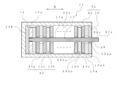
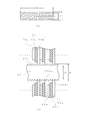
- FIG. 3 shows a schematic cross-sectional view in the axial direction of a cylindrical laminated battery (hereinafter simply referred to as a laminated battery) according to the first embodiment of the present invention.
- the laminated battery 11 shown in FIG. 3 includes an exterior body 15, a current collector 17, and an electrode body 13 housed inside the exterior body as main components.
- the exterior body 15 includes a bottomed cylindrical can 12 and a disk-shaped lid member 16 attached to the opening 12c of the cylindrical can.
- the cylindrical can 12 and the lid member 16 are made of iron, but may be other metals.
- the outer diameter of the lid member 16 is slightly larger than the inner diameter of the opening 12c of the cylindrical can, and the lid member 16 is closely fitted in the opening 12c of the cylindrical can after the electrode body 13 is stored.
- the electrode body 13 includes a positive electrode 13a including a positive electrode active material, a negative electrode 13b including a hydrogen storage alloy, and a separator 13c interposed between the positive electrode 13a and the negative electrode 13b that transmits ions but does not transmit electrons. .
- the electrode body 13 is stacked in the axial direction (X direction in FIG. 3) of the cylindrical can 12 and housed in the exterior body 15. In addition, the electrolyte solution (not shown) is hold
- Each of the positive electrode 13a, the negative electrode 13b, and the separator 13c has a disk shape with a hole in the center.
- the outer diameter of the negative electrode 13b is smaller than the inner diameter of the cylindrical can 12, and the outer edge portion 13bb of the negative electrode and the inner surface 12a of the cylindrical can are not in contact.
- the outer diameter of the positive electrode 13a is larger than the inner diameter of the cylindrical can 12, the outer edge portion 13ab of the positive electrode is in contact with the inner surface 12a of the cylindrical can, and the positive electrode 13a and the cylindrical can 12 are electrically connected.
- the outer diameter of the positive electrode 13 a is 100 ⁇ m larger than the inner diameter of the cylindrical can 12.
- the current collector 17 is made of a conductive material obtained by applying nickel plating to iron, and has a rod-shaped shaft portion 17a and a stopper portion 17b disposed at one end of the shaft portion 17a. By applying nickel plating, the current collector 17 is prevented from being corroded by the electrolyte contained in the separator 13c.
- the shaft portion 17a of the current collector 17 passes through the center of the electrode body 13 composed of the positive electrode 13a, the negative electrode 13b, and the separator 13c in the axial direction of the exterior body 15 (X direction in FIG. 3).
- the diameter of the hole provided in the center of the negative electrode 13b is smaller than the outer diameter of the shaft portion 17a.
- the peripheral edge portion 13ba of the hole of the negative electrode is in contact with the shaft portion 17a, and the negative electrode 13b and the current collector 17 are electrically connected.
- the diameter of the hole provided in the center of the positive electrode 13a is larger than the outer diameter of the shaft portion 17a, the peripheral edge portion 13aa of the positive electrode hole does not contact the shaft portion 17a, and the positive electrode 13a and the current collector 17 are electrically connected to each other. Is electrically insulated.
- the electrode body 13 is disposed so as to be sequentially stacked on the stopper portion 17b of the current collector.
- the stopper portion 17b prevents the electrode body 13 from dropping from the end portion of the current collector 17 during assembly.
- the shape of the stop portion 17b is a disk shape.
- the stopper 17b is disposed on the cylindrical can bottom 12b with the insulating plate 14 interposed therebetween.
- the insulating plate 14 prevents the current collector 17 and the cylindrical can 12 from coming into direct contact and being electrically short-circuited.
- the end of the shaft portion 17a opposite to the stop portion 17b is supported by a bearing 18 provided at the center of the lid member 16.
- the bearing 18 is made of an insulating material.
- a shaft portion penetrating the lid member 16 constitutes a positive electrode terminal 17c.
- the cylindrical can 12 functions as a negative electrode terminal.
- the outer diameter of the separator 13c is smaller than the outer diameter of the positive electrode 13a (first electrode) and larger than the outer diameter of the negative electrode 13b (second electrode). For this reason, the positive electrode 13 a and the negative electrode 13 b are completely separated by the separator 13 c in the vicinity of the inner peripheral surface of the outer package 15. For this reason, even if an electrode deform
- the electrode assembly 13 is assembled by stacking the electrode bodies 13 by sequentially inserting them into the round bar 19 so that the separator 13c is interposed between the positive electrode 13a and the negative electrode 13b.
- the diameter (d) of the round bar is slightly smaller than the diameter (D) of the current collector 17 (D> d).
- the stoppers 17b and the temporary lid member 16 'at both ends of the electrode assembly A function as a pressing plate that holds the electrode group.
- the electrode group is tightened through the stopper 17b functioning as a push plate and the temporary lid member 16 '.
- the round bar 19 is pulled out while maintaining the tightened state, and the current collector 17 is rotated while applying pressure to the stopper 17b and the temporary lid member 16 ′, and screwed into the electrode group (FIG. 4B). )reference).
- the electrode assembly B can be assembled while the clamped state of the electrode group is maintained.
- the electrode assembly B is press-fitted into the cylindrical can 12, the air is vented, and the electrolytic solution is injected.
- the lid member 16 is attached to the opening of the cylindrical can 12 and the opening of the cylindrical can 12 is crimped to seal the laminated battery.
- the outer edge portion 13ab of the positive electrode is strongly pressed against the inner surface 12a of the cylindrical can and is in close contact.
- the heat generated at the positive electrode 13a is directly transferred to the cylindrical can 12.
- the heat generated in the negative electrode 13b is transferred to the positive electrode 13a through the separator 13c. Since the separator 13c is thin and has only one sheet, it does not significantly hinder heat conduction. As described above, the heat generated in the electrodes 13a and 13b is transmitted to the cylindrical can 12 with a small temperature gradient, and the temperature rise inside the laminated battery is suppressed.
- the exterior body 12 since the exterior body 12 is exposed to the outside, it can be cooled relatively easily, so that the temperature rise can be effectively suppressed as compared with the conventional wound battery.
- the difference in temperature rise between the laminated battery according to the embodiment of the present invention and the conventional wound battery is shown as a calculation example.
- Equation 1 The overall heat transfer coefficient (U1) of the wound battery is expressed by Equation 1.
- Equation 2 The overall heat transfer coefficient (U2) of the laminated battery according to the present invention is expressed by Equation 2.
- the cooling structure according to the present invention is excellent in heat transfer nearly 100,000 times as compared with the conventional wound battery.
- the laminated battery according to the embodiment of the present invention is a positive electrode regulation or a negative electrode regulation.
- the negative electrode capacity is approximately 1.7 times the positive electrode capacity.
- the negative electrode capacity is 80% of the positive electrode capacity.
- the positive electrode capacity is 1000 mAh in all cases.
- a positive electrode-regulated battery generates oxygen gas from the positive electrode when charged at 1000 mAh or more, but does not generate hydrogen gas from the negative electrode. Oxygen gas generated from the positive electrode reacts with hydrogen occluded in the negative electrode to become water and suppresses an increase in pressure, so that the battery can be sealed.
- hydrogen gas is generated from the negative electrode. That is, when charged at 800 mAh or more, hydrogen gas is generated from the negative electrode (see reaction formula (1)). The generated hydrogen gas is occluded in the negative electrode, and the negative electrode is fully charged. Hydrogen gas that is not occluded by the negative electrode is stored inside the battery, and the pressure inside the battery rises. If there is a hydrogen gas storage chamber inside the battery, a large amount of hydrogen gas can be accumulated in the battery. Since the exterior body 15 has a sealed structure, the accumulated hydrogen gas does not leak to the outside.
- the negative electrode is said to occupy 80% of the electrode price and is expensive.
- the positive electrode-regulated battery requires a negative electrode 1.7 times as large as the positive electrode, but by setting the amount of the negative electrode to 80% of the positive electrode, the price of the electrode can be halved. It becomes. Even if the amount of the negative electrode is reduced, the battery capacity is not reduced by using the hydrogen gas stored by overcharging.
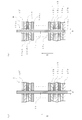
- FIG. 5 is a schematic cross-sectional view in the axial direction of a pipe type laminated battery (hereinafter simply referred to as a laminated battery) according to the second embodiment of the present invention.
- a laminated battery 21 shown in FIG. 5 includes an exterior body 25, a current collector 27, and an electrode body 23 housed in the exterior body as main components.
- the exterior body 25 includes a circular tube 22 and a disk-shaped lid member 26 attached to the opening portions 22b at both ends of the circular tube 22.
- the circular tube 22 and the lid member 26 are made of iron, but may be other metals.
- the outer diameter of the lid member 26 is slightly larger than the inner diameter of the opening 22b of the circular tube, and the lid member 26 is tightly fitted in the opening 22b of the circular tube after the electrode body 23 is stored.
- the electrode body 23 includes a positive electrode 23a including a positive electrode active material, a negative electrode 23b including a hydrogen storage alloy, and a separator 23c interposed between the positive electrode 23a and the negative electrode 23b to transmit ions but not transmit electrons. .
- the electrode body 23 is laminated
- the electrolytic solution is held in the separator 23c.
- Each of the positive electrode 23a, the negative electrode 23b, and the separator 23c has a disk shape with a hole in the center.
- the outer diameter of the negative electrode 23b is smaller than the inner diameter of the circular tube 22, and the outer edge 23bb of the negative electrode is not in contact with the inner surface 22a of the circular tube.
- the outer diameter of the positive electrode 23 a is larger than the inner diameter of the circular tube 22, and the outer edge 23 ab of the positive electrode is in contact with the inner surface 22 a of the circular tube 22 and is electrically connected to the circular tube 22.
- the outer diameter of the positive electrode 23 a is 100 ⁇ m larger than the inner diameter of the circular tube 22.
- the current collector 27 is made of a conductive material obtained by nickel-plating rod-shaped iron, and has a shaft portion 27a at a central portion and end portions 27b at both end portions. By applying nickel plating, the current collector 27 is prevented from being corroded by the electrolytic solution contained in the separator 23c.
- the shaft portion 27a of the current collector 27 passes through the center of the electrode body 23 composed of the positive electrode 23a, the negative electrode 23b, and the separator 23c in the axial direction of the exterior body 25 (X direction in FIG. 5).
- the diameter of the hole provided in the center of the negative electrode 23b is smaller than the outer diameter of the shaft portion 27a, the peripheral edge portion 23ba of the negative electrode hole is in contact with the shaft portion 27a, and the negative electrode 23b and the current collector 27 are electrically It is connected.
- the diameter of the hole provided in the center of the positive electrode 23a is larger than the outer diameter of the shaft portion 27a, the peripheral edge portion 23aa of the positive electrode hole is not in contact with the shaft portion 27a, and the positive electrode 23a and the current collector 27 are electrically connected. Is electrically insulated.
- the electrode body 23 is sequentially stacked in a skewered state on the shaft portion 27a of the current collector.
- the current collector 27 is supported at both end portions 27b by a bearing 28 provided at the center of the lid member 26.
- the bearing 28 is made of an insulating material.
- An end portion 27b of the current collector passing through the lid member 26 constitutes a negative electrode terminal 27c.
- the circular tube 22 functions as a positive electrode terminal.
- connection fitting 29 is attached to the laminated battery 21 .
- the connection fitting 29 is disposed between the laminated battery 21 and the adjacent laminated battery 21 ′ so as to face the lid member 26 of the laminated battery 21.
- the connection fitting 29 is a columnar metal, and its axial direction coincides with the axial direction of the current collector 27 (X direction in FIG. 6).
- a hole 29aa perpendicular to the upper surface 29a is provided at the center of the upper surface 29a (the left surface in the figure) of the connection fitting 29 so that the current collector 27 ′ of the adjacent stacked battery 21 ′ can be fitted. ing.
- a hole 29ba perpendicular to the bottom surface 29b is provided at the center of the bottom surface 29b (right side surface in the figure) of the connection fitting 29 so that the insulating member 24 can be fitted therein.
- a hole 24a is provided in the center of the insulating member 24 in a direction perpendicular to the bottom surface 29b so that the shaft portion 27b of the current collector of the laminated battery 21 can be fitted.
- the stacked batteries 21 adjacent to each other using the connection fitting 29 can be connected in series to form the assembled battery 20.
- the laminated battery 61 includes an exterior body 65, a current collector 67, and an electrode body 63 housed inside the exterior body as main components.
- the exterior body 65 includes a circular tube 62 and disk-shaped lid members 66a and 66b attached to the openings 62c at both ends of the circular tube 62, and is hermetically sealed to accommodate the electrode body 63 therein. A space is formed.
- the circular tube 62 that forms the body portion of the exterior body 65 is made of nickel-plated steel, but may be made of stainless steel plated with nickel.
- the current collector 67 has a rod-shaped shaft portion 67a at the center portion and a disk-shaped stopper portion 67b provided at one end of the shaft portion 67a.
- the current collector 67 is made of a conductive material in which steel is plated with nickel.
- the lid member 66 is made of polypropylene and includes a first lid member 66a (right side in the figure) and a second lid member 66b.
- the first lid member 66a supports an end portion 67c of the current collector.
- the second lid member 66b covers the stop portion 67b.
- the end 67c of the current collector is provided with a screw groove 67ca. By screwing the nut 64 into the screw groove 67ca, the electrode body 63 disposed between the lid members 66a and 66b can be tightened. Yes.
- a sealing material 68 is applied to the outer periphery of the lid member 66 and serves to make the interior of the exterior body 65 airtight. Asphalt pitch is used as the sealing material 68, but other materials may be used as long as they have sealing properties.
- the electrode body 63 includes a positive electrode 63a including a positive electrode active material, a negative electrode 63b including a hydrogen storage alloy, and a separator 63c that is interposed between the positive electrode 63a and the negative electrode 63b and transmits ions but does not transmit electrons. .
- the electrode body 63 is stacked in the axial direction of the circular tube 62 (X direction in FIG. 7) and housed in the exterior body 65. Note that the electrolytic solution is held in the separator 63c.
- the positive electrode 63a, the negative electrode 63b, and the separator 63c all have a disk shape with a hole in the center.
- the outer diameter of the positive electrode 63a is smaller than the inner diameter of the circular tube 62, and the outer edge 63ab of the positive electrode and the inner surface 62a of the circular tube are not in contact with each other.
- the outer diameter of the negative electrode 63 b is larger than the inner diameter of the circular tube 62, the outer edge 63 bb of the negative electrode is in contact with the inner surface 62 a of the circular tube 62, and the negative electrode 63 b is electrically connected to the circular tube 62.
- the outer diameter of the negative electrode 63 b is 100 ⁇ m larger than the inner diameter of the circular tube 62.
- the shaft portion 67a of the current collector 67 passes through the center of the electrode body 63 composed of the positive electrode 63a, the negative electrode 63b, and the separator 63c in the axial direction of the exterior body 65 (X direction in FIG. 7).
- the diameter of the hole provided in the center of the positive electrode 63a is smaller than the outer diameter of the shaft portion 67a, the peripheral edge portion 63aa of the positive electrode hole is in contact with the shaft portion 67a, and the positive electrode 63a is electrically connected to the current collector 67. It is connected.
- the diameter of the hole provided at the center of the negative electrode 63b is larger than the outer diameter of the shaft portion 67a, and the peripheral portion 63ba of the hole of the negative electrode is not in contact with the shaft portion 67a.
- the collector stop portion 67b is covered with polypropylene and housed inside the second lid member 66b.
- the end 67c of the current collector passing through the first lid member 66a constitutes a positive electrode terminal.
- the circular tube 62 functions as a negative electrode terminal.
- FIG. 8A shows a configuration diagram of an assembled battery in which stacked batteries are connected using a bracket. That is, the assembled battery 60 is configured by connecting a plurality of stacked batteries 61 using a bracket 69 shown in FIG.
- the bracket 69 is a metal plate having two large and small holes, and is provided with a hole 69a into which the circular tube 62 of the laminated battery is fitted and a hole 69b into which the positive terminal 67c is fitted.
- the circular tube 62 of the laminated battery is attached to the hole 69a of the bracket.
- An end portion 67c that functions as a positive electrode terminal of the adjacent stacked battery is inserted into the other hole 69b of the bracket and attached to the bracket 69 with a nut 64a.
- an assembled battery may be configured using the cylindrical laminated battery 11 shown in FIG. 3 or the pipe-type laminated battery 21 shown in FIG.
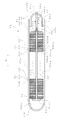
- FIG. 9 shows a schematic cross-sectional view in the axial direction of a capsule-type laminated battery (hereinafter simply referred to as a laminated battery) according to the third embodiment of the present invention.
- the laminated battery 31 includes an exterior body 35, a current collector 37, and an electrode body 33 housed inside the exterior body as main components.
- the exterior body 35 includes a bottomed cylindrical outer structure 32 and a lid member 36 attached to the opening 32 c of the outer structure 32.
- the outer structure 32 and the lid member 36 are obtained by applying nickel plating to iron, but may be a metal such as aluminum or titanium.
- the outer structure 32 and the lid member 36 have cylindrical side portions 32a and 36a and bulged portions 32b and 36b bulged in a dome shape at the bottom.
- the outer diameter of the side portion 36 a of the lid member is smaller than the inner diameter of the opening 32 c of the outer structure 32.
- the lid member covers the opening 32c such that the bulging portion 36b bulges outward from the opening 32c of the outer structure.
- the lid member 36 is joined to the outer structure 32 via an insulating seal member 38.
- the insulating seal member 38 has a role of electrically insulating the outer structure body 32 and the lid member 36 and a role of forming a sealed space inside the exterior body 35 by sealing at the joint portion.
- the insulating seal member 38 is made of a material having both insulating properties and sealing properties, for example, asphalt pitch.
- the electrode body 33 includes a positive electrode 33a including a positive electrode active material, a negative electrode 33b including a hydrogen storage alloy, and a separator 33c interposed between the positive electrode 33a and the negative electrode 33b that transmits ions but does not transmit electrons. .
- the electrode body 33 is stacked in the axial direction (X direction in FIG. 9) of the outer structure 32 and housed in the exterior body 35.
- the electrolytic solution is held in the separator 33c.
- the positive electrode 33a, the negative electrode 33b, and the separator 33c all have a disk shape with a hole in the center.
- the outer diameter of the positive electrode 33a is smaller than the inner diameter of the outer structure 32, and the outer edge portion 33aa of the positive electrode and the inner surface 32aa of the outer structure are not in contact with each other.
- the outer diameter of the negative electrode 33 b is larger than the inner diameter of the outer structure 32, the outer edge portion 33 ba of the negative electrode is in contact with the inner surface 32 aa of the outer structure 32, and the negative electrode 33 b is electrically connected to the outer structure 32.
- the outer diameter of the negative electrode 33 b is 100 ⁇ m larger than the inner diameter of the outer structure 32.
- the current collector 37 is made of a conductive material in which nickel is plated on iron, and has a rod-shaped shaft portion 37a and a stopper portion 37b attached to one end of the shaft portion 37a.
- the shaft portion 37a of the current collector 37 passes through the center of the electrode body 33 composed of the positive electrode 33a, the negative electrode 33b, and the separator 33c in the axial direction of the exterior body 35 (X direction in FIG. 9).
- the diameter of the hole provided in the center of the positive electrode 33a is smaller than the outer diameter of the shaft portion 37a, the peripheral portion 33ab of the positive hole is in contact with the shaft portion 37a, and the positive electrode 33a and the current collector 37 are electrically It is connected.
- the diameter of the hole provided in the center of the negative electrode 33b is larger than the outer diameter of the shaft portion 37a, and the peripheral portion 33bb of the hole of the negative electrode is not in contact with the shaft portion 37a.
- the electrode body 33 is disposed so as to be sequentially stacked on the current collector stop portion 37 b, and at this time, the stop portion 37 b prevents the electrode body 33 from falling off the end of the current collector 37.
- Push plates 34a made of an insulating material are disposed at both ends of the stacked electrode bodies 33, and the electrode bodies 33 are prevented from being damaged when the electrode bodies 33 are stacked and pressed.
- the pressing plate 34a is preferably an insulating material and a structural material, and is preferably polypropylene.
- the shape of the stop portion 37b is a disc shape, but may be a rectangle.
- the stopper 37b is not in contact with the bulging portion 32b at the bottom of the outer structure, and the stopper 37b and the outer structure 32a are electrically insulated.
- An end portion 37c of the shaft portion opposite to the stop portion 37b passes through a hole 36c provided in the center of the lid member 36 and protrudes outward (right direction in the figure) of the lid member 36.
- the end portion 37c penetrating the lid member 36 constitutes a positive electrode terminal.
- the outer structure 32 functions as a negative electrode terminal.
- a hydrogen storage chamber 39 is provided in the inner space of the bulging portions 32b and 36b. That is, the hydrogen storage chamber 39 is disposed in the space inside the outer package surrounded by the inner surfaces 32ba and 36ba of the bulging portion and the electrode body 33.
- FIG. 10 shows a rectangular laminated battery (hereinafter simply referred to as a laminated battery) according to a fourth embodiment of the present invention.
- the battery as a whole has a square shape.
- the laminated battery 71 includes an exterior body 75, a current collector 77, and an electrode body 74 housed inside the exterior body as main components.
- the exterior body 75 includes a body member 72 and a lid member 73.
- the body member 72 is a bottomed rectangular container. By covering the opening 72 c of the body member 72 with the lid member 73, a sealed space can be formed inside the body member 72.
- the body member 72 and the lid member 73 are made of iron, but may be other metals.
- the electrode body 74 includes a positive electrode 74a including a positive electrode active material, a negative electrode 74b including a hydrogen storage alloy, and a separator 74c that is interposed between the positive and negative electrodes 74a and 74b and transmits ions but does not transmit electrons. Yes.
- the separator 74c has a role of preventing a short circuit between the positive and negative electrodes 74a and 74b and holding an electrolytic solution.
- the positive electrode 74a and the negative electrode 74b are stacked in the axial direction of the trunk member 72 (Y direction in FIG. 10) via the separator 74c and housed in the exterior body 75.
- the positive electrode 74a, the negative electrode 74b, and the separator 74c are all sheet-like.
- the outer dimension of the negative electrode 74b is smaller than the inner dimension of the body member 72, and the outer edge portion 74bb of the negative electrode and the inner surface 72a of the body member are in contact with each other. Absent.
- the outer dimension of the positive electrode 74 a is larger than the inner dimension of the body member 72, the outer edge portion 74 ab of the positive electrode is in contact with the inner surface 72 a of the body member 72 with pressure, and the positive electrode 74 a is electrically connected to the body member 72.
- the outer dimension of the positive electrode 74 a is 100 ⁇ m larger than the inner dimension of the body member 72.
- the current collector 77 is made of a conductive material in which nickel is plated on iron.
- the current collector 77 has a countersunk cone part 77b and a shaft part 77a following it, and constitutes a countersunk screw as a whole.
- the electrode body 74 is provided with holes 74ba and 74ca through which the shaft portion 77a of the current collector 77 passes.
- the electrode body 74 is stacked and stored in the axial direction of the exterior body 75 (Y direction in FIG. 10).
- the diameter of the hole 74ba provided in the negative electrode 74b is smaller than the outer diameter of the shaft portion 77a, the negative electrode 74b is in contact with the shaft portion 77a, and the negative electrode 74b and the current collector 77 are electrically connected.
- the diameter of the hole 74aa provided in the positive electrode 74a is larger than the outer diameter of the shaft portion 77a, and the positive electrode 74a is not in contact with the shaft portion 77a.
- the four current collectors 77 are connected to each other by a connecting plate 77d provided below the electrode body 74. That is, the current collector 77 and the connection plate 77d are connected by screwing the screw portion 77c into the screw hole 77da provided in the connection plate 77d at the lower end 77ca of the current collector.
- the electrode bodies 74 are arranged so as to be sequentially stacked on the connection plate 77 d, and the connection plate 77 d prevents the electrode body 74 from dropping from the end of the current collector 77.
- An insulating plate 76b is disposed between the trunk member bottom portion 72b and the connecting plate 77d.
- the connecting plate 77d comes into contact with the trunk member bottom portion 72b, and the current collector 77 and the trunk member 72 are electrically short-circuited. Is preventing. Specifically, the connecting plate 77d is surrounded by an insulating plate 76b made of polypropylene.
- the lid member 73 has a flat plate portion 73a and a bent portion 73b that bends at a right angle from the flat plate portion.
- An insulating plate 76a is disposed inside the bent portion 73b and in the opening 72c of the body member. The insulating plate 76a prevents the uppermost electrode body 74 and the lid member 73 from being electrically short-circuited.
- a groove 76aa into which the outer edge of the opening of the body member 72 is fitted is provided on the surface of the insulating plate 76a opposite to the lid member 73.
- a sealing material 80 made of asphalt pitch is disposed between the groove 76aa and the outer edge of the opening of the body member 72 to keep the inside of the exterior body 75 airtight.
- a sealing material 80 made of asphalt pitch is also disposed in the hole through which the current collector shaft 77a of the insulating plate 76a passes.
- the lid member 73 is connected to the connecting plate 77d by a current collector 77 that acts as a countersunk screw.
- the body member 72 functions as a positive electrode terminal, and the lid member 73 functions as a negative electrode terminal.
- FIG. 11 shows a schematic configuration diagram when the assembled battery 70 is configured using the laminated battery 71.
- a plurality of stacked batteries are connected in series by causing the flat plate portion 73a of the lid member of the stacked battery 71 and the bottom portion 72b of the body member of the adjacent stacked battery to face each other.
- the stacked batteries connected in series are sandwiched between the positive electrode terminal plate 78 a and the negative electrode terminal plate 78 b to constitute the assembled battery 70.
- a positive electrode terminal plate 78a that is in contact with the body member 72 and a negative electrode terminal plate 78b that is in contact with the lid member 73 are disposed inside the housing 70a, and a plurality of gaps are provided between the positive electrode terminal plate 78a and the negative electrode terminal plate 78b.
- the battery pack 70 is configured by housing the laminated battery 71.
- the assembled battery 70 is cooled by supplying cooling air from the outside to the inside 70 a by the suction fan 79 a and the pushing fan 79 b.
- the output of the assembled battery is taken out from the positive terminal plate 78a and the negative terminal plate 78b by a cable (not shown).
- the invention according to this embodiment is different from the embodiments described so far in part of the structure of the current collector.
- the laminated battery 21 of the second embodiment is taken as an example, and the difference from the second embodiment will be mainly described with reference to FIG.
- the side surface of the current collector 27 is threaded (see FIG. 12A). That is, the side surface of the current collector 27 has a thread groove having a trough diameter d and a crest diameter D (d ⁇ D).
- the specification of the screw is the M screw referred to in JIS, but may be the ISO specification.
- FIG. 12B is a partial cross-sectional view schematically showing the relationship between the current collector 27 and the electrode body 23.
- the diameter of the hole 23ba provided in the negative electrode 23b is smaller than the diameter (d) of the valley of the screw portion 27c, and the negative electrode 23b is screwed into the shaft portion 27a and makes strong contact with the current collector 27.
- the negative electrode 23b and the current collector 27 are electrically connected.
- the diameter of the hole 23aa provided in the positive electrode 23a is larger than the diameter (D) of the crest of the screw portion 27c, the positive electrode 23a does not contact the shaft portion 27a, and the positive electrode 23a and the current collector 27 are electrically insulated.
- D diameter
- the multilayer battery of the first embodiment of the present invention was charged at 0.5 C to 8 C, and the internal temperature and surface temperature of the multilayer battery were examined after full charge.
- the internal temperature was measured by attaching a thermocouple to the current collector, and the surface temperature was measured by attaching a thermocouple to the surface of the exterior body of the laminated battery.
- the room temperature was 15 ° C., and the laminated battery was measured with a fan at a rate of 1 m / s.
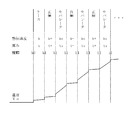
- FIG. 13 is a graph showing the difference between the internal temperature of the battery after charging and the room temperature, with each charging rate as a parameter. That is, in FIG. 13, the vertical axis indicates the temperature difference in degrees Celsius, and the horizontal axis indicates the elapsed time in minutes. It can be seen that at a charge rate of 2C or less, the difference (temperature rise) between the battery internal temperature and room temperature is 4 ° C. or less, which is very small. This seems to be because heat is not stored inside the battery because heat is released simultaneously with heat generated by charging.
- the laminated battery according to the present invention can be suitably used as a power storage device not only for industrial use but also for consumer use.
- Cylindrical laminated battery 12 Cylindrical can (a: side part inner surface) 13 Electrode body (a: positive electrode, b: negative electrode, c: separator) 14 Insulating plate 15 Exterior body 16 Lid member 17 Current collector (a: shaft part, b: stopper part, c: positive electrode terminal) 19 Hydrogen storage room 20 Battery pack 21 Pipe type laminated battery 22 Circular tube (a: inner surface) 23 electrode body (a: positive electrode, b: negative electrode, c: separator) 24 Insulating member 25 Exterior body 26 Lid member 27 Current collector 29 Connection fitting 31 Capsule battery 32 External structure (a: side part, b: bulging part) 33 Electrode body (a: positive electrode, b: negative electrode, c: separator) 35 exterior body 36 lid member 37 current collector (a: shaft part, b: stopper part, c: end part) 38 Insulating seal member 39 Hydrogen storage chamber 60 Battery assembly 61 Pipe-
Landscapes
- Chemical & Material Sciences (AREA)
- Chemical Kinetics & Catalysis (AREA)
- Electrochemistry (AREA)
- General Chemical & Material Sciences (AREA)
- Engineering & Computer Science (AREA)
- Manufacturing & Machinery (AREA)
- Inorganic Chemistry (AREA)
- Secondary Cells (AREA)
- Bipolar Transistors (AREA)
- Connection Of Batteries Or Terminals (AREA)
- Sealing Battery Cases Or Jackets (AREA)
- Cell Electrode Carriers And Collectors (AREA)
- Battery Mounting, Suspending (AREA)
- Battery Electrode And Active Subsutance (AREA)
- Cooling Or The Like Of Semiconductors Or Solid State Devices (AREA)
- Cooling Or The Like Of Electrical Apparatus (AREA)
Applications Claiming Priority (2)
| Application Number | Priority Date | Filing Date | Title |
|---|---|---|---|
| JP2011-205597 | 2011-09-21 | ||
| JP2011205597 | 2011-09-21 |
Publications (1)
| Publication Number | Publication Date |
|---|---|
| WO2013042640A1 true WO2013042640A1 (ja) | 2013-03-28 |
Family
ID=47914407
Family Applications (1)
| Application Number | Title | Priority Date | Filing Date |
|---|---|---|---|
| PCT/JP2012/073749 Ceased WO2013042640A1 (ja) | 2011-09-21 | 2012-09-15 | 積層電池およびこれを用いた組電池 |
Country Status (2)
| Country | Link |
|---|---|
| JP (2) | JP5531220B2 (https=) |
| WO (1) | WO2013042640A1 (https=) |
Cited By (8)
| Publication number | Priority date | Publication date | Assignee | Title |
|---|---|---|---|---|
| JP2013157158A (ja) * | 2012-01-29 | 2013-08-15 | Institute Of Energy Engineering Inc | 積層電池および積層電池システム |
| WO2014092031A1 (ja) * | 2012-12-16 | 2014-06-19 | エクセルギー・パワー・システムズ株式会社 | 電極ブロック、積層電池および積層電池の組立方法 |
| EP2782181A4 (en) * | 2011-12-19 | 2015-08-19 | Exergy Power Systems Inc | LAYER, COMPOSITE BATTERY WITH LAYER CELL AND METHOD OF COMPOSING LAYER CELL |
| FR3029536A1 (fr) * | 2013-08-12 | 2016-06-10 | Ergosup | Stockage de masse d'electricite utilisant un metal electrolysable comme vecteur |
| US10249919B2 (en) | 2014-08-21 | 2019-04-02 | Lg Chem, Ltd. | Battery cell having improved cooling performance |
| US10446805B2 (en) | 2016-09-16 | 2019-10-15 | Toyota Jidosha Kabushiki Kaisha | Stacked battery |
| CN111129363A (zh) * | 2019-12-09 | 2020-05-08 | 金山电化工业(惠州)有限公司 | 防高温新型氯化铵电池 |
| EP4047717A1 (de) * | 2021-02-17 | 2022-08-24 | Volkswagen Ag | Batterie |
Families Citing this family (4)
| Publication number | Priority date | Publication date | Assignee | Title |
|---|---|---|---|---|
| KR102108208B1 (ko) * | 2015-07-30 | 2020-05-07 | 주식회사 엘지화학 | 원형 전극을 포함하는 원통형 이차전지 |
| JP6288655B2 (ja) * | 2016-06-20 | 2018-03-07 | エクセルギー・パワー・システムズ株式会社 | リバーシブル燃料電池蓄電池 |
| EP4006935B1 (en) | 2019-08-20 | 2026-03-25 | GS Yuasa International Ltd. | Method for producing electricity storage element, and electricity storage element |
| JP6931950B1 (ja) * | 2020-03-27 | 2021-09-08 | 株式会社堤水素研究所 | 固体電解質電池 |
Citations (7)
| Publication number | Priority date | Publication date | Assignee | Title |
|---|---|---|---|---|
| JPS57500854A (https=) * | 1980-06-13 | 1982-05-13 | ||
| JPH05217607A (ja) * | 1991-10-28 | 1993-08-27 | Globe Union Inc | 金属酸化物水素電池 |
| JPH11274004A (ja) * | 1998-03-23 | 1999-10-08 | Asahi Glass Co Ltd | 電気化学素子 |
| JP2000048854A (ja) * | 1998-07-31 | 2000-02-18 | Toshiba Battery Co Ltd | 円筒型二次電池 |
| JP3069054U (ja) * | 1999-11-16 | 2000-05-30 | 泰和 楊 | 柱型単電極組蓄電装置 |
| JP2000268854A (ja) * | 1999-03-19 | 2000-09-29 | Toyota Motor Corp | ニッケル水素電池 |
| JP2006092828A (ja) * | 2004-09-22 | 2006-04-06 | Sanyo Electric Co Ltd | 組電池 |
Family Cites Families (1)
| Publication number | Priority date | Publication date | Assignee | Title |
|---|---|---|---|---|
| JPH04171849A (ja) * | 1990-11-06 | 1992-06-19 | Toshiba Corp | ウェファ冷却方式 |
-
2012
- 2012-09-15 WO PCT/JP2012/073749 patent/WO2013042640A1/ja not_active Ceased
- 2012-09-15 JP JP2012203739A patent/JP5531220B2/ja active Active
-
2013
- 2013-04-06 JP JP2013080027A patent/JP5380715B2/ja active Active
Patent Citations (7)
| Publication number | Priority date | Publication date | Assignee | Title |
|---|---|---|---|---|
| JPS57500854A (https=) * | 1980-06-13 | 1982-05-13 | ||
| JPH05217607A (ja) * | 1991-10-28 | 1993-08-27 | Globe Union Inc | 金属酸化物水素電池 |
| JPH11274004A (ja) * | 1998-03-23 | 1999-10-08 | Asahi Glass Co Ltd | 電気化学素子 |
| JP2000048854A (ja) * | 1998-07-31 | 2000-02-18 | Toshiba Battery Co Ltd | 円筒型二次電池 |
| JP2000268854A (ja) * | 1999-03-19 | 2000-09-29 | Toyota Motor Corp | ニッケル水素電池 |
| JP3069054U (ja) * | 1999-11-16 | 2000-05-30 | 泰和 楊 | 柱型単電極組蓄電装置 |
| JP2006092828A (ja) * | 2004-09-22 | 2006-04-06 | Sanyo Electric Co Ltd | 組電池 |
Cited By (14)
| Publication number | Priority date | Publication date | Assignee | Title |
|---|---|---|---|---|
| US9876251B2 (en) | 2011-12-19 | 2018-01-23 | Exergy Power Systems, Inc. | Layer cell, assembled battery including layer cell, and method for assembling layer cell |
| EP2782181A4 (en) * | 2011-12-19 | 2015-08-19 | Exergy Power Systems Inc | LAYER, COMPOSITE BATTERY WITH LAYER CELL AND METHOD OF COMPOSING LAYER CELL |
| US10381676B2 (en) | 2011-12-19 | 2019-08-13 | Exergy Power Systems, Inc. | Layer cell, assembled battery including layer cell, and method for assembling layer cell |
| JP2013157158A (ja) * | 2012-01-29 | 2013-08-15 | Institute Of Energy Engineering Inc | 積層電池および積層電池システム |
| JP5691048B2 (ja) * | 2012-12-16 | 2015-04-01 | エクセルギー・パワー・システムズ株式会社 | 電極ブロック、積層電池および積層電池の組立方法 |
| WO2014092031A1 (ja) * | 2012-12-16 | 2014-06-19 | エクセルギー・パワー・システムズ株式会社 | 電極ブロック、積層電池および積層電池の組立方法 |
| US10388982B2 (en) | 2012-12-16 | 2019-08-20 | Exergy Power Systems, Inc. | Electrode block, layered cell, and assembly method for layered cell |
| FR3029536A1 (fr) * | 2013-08-12 | 2016-06-10 | Ergosup | Stockage de masse d'electricite utilisant un metal electrolysable comme vecteur |
| WO2017032835A1 (fr) * | 2013-08-12 | 2017-03-02 | Ergosup | Stockage d'électricité utilisant un métal électrolysable comme vecteur |
| US10249919B2 (en) | 2014-08-21 | 2019-04-02 | Lg Chem, Ltd. | Battery cell having improved cooling performance |
| US10446805B2 (en) | 2016-09-16 | 2019-10-15 | Toyota Jidosha Kabushiki Kaisha | Stacked battery |
| CN111129363A (zh) * | 2019-12-09 | 2020-05-08 | 金山电化工业(惠州)有限公司 | 防高温新型氯化铵电池 |
| EP4047717A1 (de) * | 2021-02-17 | 2022-08-24 | Volkswagen Ag | Batterie |
| CN114944519A (zh) * | 2021-02-17 | 2022-08-26 | 大众汽车股份公司 | 电池 |
Also Published As
| Publication number | Publication date |
|---|---|
| JP2013152952A (ja) | 2013-08-08 |
| JP2013080698A (ja) | 2013-05-02 |
| JP5380715B2 (ja) | 2014-01-08 |
| JP5531220B2 (ja) | 2014-06-25 |
Similar Documents
| Publication | Publication Date | Title |
|---|---|---|
| JP5678279B2 (ja) | 積層電池 | |
| WO2013042640A1 (ja) | 積層電池およびこれを用いた組電池 | |
| EP2871699B1 (en) | Electrode block, layered battery, and assembly method for layered battery | |
| US7842416B2 (en) | Rechargeable battery having a cap assembly | |
| JP5417579B1 (ja) | 積層電池 | |
| JP5776005B2 (ja) | 密閉型二次電池 | |
| JP2004253295A (ja) | 蓄電素子 | |
| US8802262B2 (en) | Secondary battery | |
| KR20060037839A (ko) | 이차 전지 | |
| CN101313427B (zh) | 蓄电池、蓄电池组及其制造方法 | |
| KR102920621B1 (ko) | 이차전지 및 이를 포함하는 디바이스 | |
| KR102149297B1 (ko) | 2차 전지 | |
| RU2575480C1 (ru) | Слоистый элемент, собранная батарея, включающая слоистый элемент, и способ сборки слоистого элемента | |
| JP7632828B2 (ja) | 二次電池およびこれを含むデバイス | |
| WO2019039297A1 (ja) | 蓄電素子 |
Legal Events
| Date | Code | Title | Description |
|---|---|---|---|
| 121 | Ep: the epo has been informed by wipo that ep was designated in this application |
Ref document number: 12834282 Country of ref document: EP Kind code of ref document: A1 |
|
| NENP | Non-entry into the national phase |
Ref country code: DE |
|
| WWE | Wipo information: entry into national phase |
Ref document number: 14350314 Country of ref document: US |
|
| 122 | Ep: pct application non-entry in european phase |
Ref document number: 12834282 Country of ref document: EP Kind code of ref document: A1 |
|
| NENP | Non-entry into the national phase |
Ref country code: JP |