WO2013042563A1 - スケール装置 - Google Patents
スケール装置 Download PDFInfo
- Publication number
- WO2013042563A1 WO2013042563A1 PCT/JP2012/073014 JP2012073014W WO2013042563A1 WO 2013042563 A1 WO2013042563 A1 WO 2013042563A1 JP 2012073014 W JP2012073014 W JP 2012073014W WO 2013042563 A1 WO2013042563 A1 WO 2013042563A1
- Authority
- WO
- WIPO (PCT)
- Prior art keywords
- scale
- base
- guide
- attached
- base portion
- Prior art date
- Legal status (The legal status is an assumption and is not a legal conclusion. Google has not performed a legal analysis and makes no representation as to the accuracy of the status listed.)
- Ceased
Links
Images




Classifications
-
- G—PHYSICS
- G01—MEASURING; TESTING
- G01D—MEASURING NOT SPECIALLY ADAPTED FOR A SPECIFIC VARIABLE; ARRANGEMENTS FOR MEASURING TWO OR MORE VARIABLES NOT COVERED IN A SINGLE OTHER SUBCLASS; TARIFF METERING APPARATUS; MEASURING OR TESTING NOT OTHERWISE PROVIDED FOR
- G01D5/00—Mechanical means for transferring the output of a sensing member; Means for converting the output of a sensing member to another variable where the form or nature of the sensing member does not constrain the means for converting; Transducers not specially adapted for a specific variable
- G01D5/26—Mechanical means for transferring the output of a sensing member; Means for converting the output of a sensing member to another variable where the form or nature of the sensing member does not constrain the means for converting; Transducers not specially adapted for a specific variable characterised by optical transfer means, i.e. using infrared, visible, or ultraviolet light
- G01D5/32—Mechanical means for transferring the output of a sensing member; Means for converting the output of a sensing member to another variable where the form or nature of the sensing member does not constrain the means for converting; Transducers not specially adapted for a specific variable characterised by optical transfer means, i.e. using infrared, visible, or ultraviolet light with attenuation or whole or partial obturation of beams of light
- G01D5/34—Mechanical means for transferring the output of a sensing member; Means for converting the output of a sensing member to another variable where the form or nature of the sensing member does not constrain the means for converting; Transducers not specially adapted for a specific variable characterised by optical transfer means, i.e. using infrared, visible, or ultraviolet light with attenuation or whole or partial obturation of beams of light the beams of light being detected by photocells
- G01D5/347—Mechanical means for transferring the output of a sensing member; Means for converting the output of a sensing member to another variable where the form or nature of the sensing member does not constrain the means for converting; Transducers not specially adapted for a specific variable characterised by optical transfer means, i.e. using infrared, visible, or ultraviolet light with attenuation or whole or partial obturation of beams of light the beams of light being detected by photocells using displacement encoding scales
- G01D5/34746—Linear encoders
- G01D5/34753—Carriages; Driving or coupling means
Definitions
- the present invention relates to a scale device mainly used for precise control of a linear motion device such as a base position control of a coating device.
- a flat panel display such as a liquid crystal display or a plasma display uses a substrate coated with a resist solution (referred to as a coated substrate).
- the coated substrate is formed by a coating apparatus that uniformly coats a coating solution such as a resist solution or a chemical solution on the substrate.
- the coating apparatus 1 includes a transport unit 2 that transports the substrate W and a coating unit 3 that applies a coating solution to the substrate.
- the coating unit 3 includes a base having a slit extending in a direction perpendicular to the direction in which the substrate W is transported by the transport unit 2, and discharges the coating liquid from the slit while transporting the substrate W at a predetermined speed. A coating film is formed.
- the amount of the coating liquid discharged from the slit is made uniform, and the height of the die is accurately controlled, for example, in units of microns, and the distance between the die and the substrate W is made uniform. Need to keep on.
- a scale is incorporated in a linear motion device, and position control of a positioning target is performed based on position information obtained from the scale.
- the technique to perform is conventionally used for the structure of the coating part of a coating device. For example, as shown in FIG. 7A, in a coating unit 90 that controls the height of the base 91 by moving up and down a beam 92 on which the base 91 is mounted, a support unit that supports the beam 92 via a linear guide 95. A scale 93 is attached to 96, and a read head 94 is attached to the beam 92.
- the reading head 94 reads the scale 93 and controls the position of the reading head 94 based on the value, thereby controlling the height of the beam 92 and the base 91, and the base 91 and the substrate W. The distance is kept constant.
- the scale 93 is attached to the base portion 96 by bolt fixing at a fixing portion 97 and a fixing portion 98 in the vicinity of both ends of the scale 93.
- the support part 96 of the application part 90 shown in FIG. 7A is thermally expanded and is in the state of FIG. 7B, the support part 96 is shown in FIG.
- the positions of the fixing portion 97 and the fixing portion 98 also change, and are displaced to the positions indicated by the fixing portion 97 ′ and the fixing portion 98 ′.
- the scale 93 is stretched, and the scale interval of the scale 93 is increased. End up.
- the position where the scale 93 indicates the coordinate A is different between the case and the case of FIG. That is, the position of the base 91 cannot be accurately controlled, and it has been difficult to apply the base 91 with a uniform film thickness while keeping the distance between the base 91 and the substrate W uniform.
- One method for preventing this problem is to form the support portion 96 with a low thermal expansion material.
- the low thermal expansion material is very difficult.
- the support portion 96 is a member that supports the base 91 and has a large shape. Therefore, replacing it with a low thermal expansion material leads to a significant increase in the manufacturing cost of the coating apparatus. Therefore, it is difficult to adopt this method when manufacturing a coating apparatus with a budget as low as possible.
- a scale device of the present invention is a scale device comprising a scale in which scales are arranged in one direction, a base portion to which the scales are attached, and a read head that reads the scales of the scales,
- the scale has a fixed portion fixed to the base portion at one end in the scale direction, which is a direction in which the scale is attached, and a guide mounting portion attached to the base portion via a linear guide at the opposite end portion.
- the direction of movement of the linear motion guide and the scale direction are the same.
- the scale is attached to the base portion with the fixed portion fixed to the base portion at one end in the scale direction and the guide attaching portion attached to the base portion via the linear guide at the opposite end portion. Since the linear movement guide moves in the same direction as the scale direction, the scale will expand and contract in the scale direction by operating the linear motion guide even if the base part is thermally expanded or contracted. Therefore, it is possible to maintain the coordinate accuracy of the scale and to perform accurate position control with the reading head.
- the fixing portion may be closer to the mounting member than the guide mounting portion with respect to the scale direction.
- the scale device includes a scale in which scales are arranged in one direction, a bracket for attaching the scales, a base portion for attaching the brackets, and a read head for reading the scales of the scales.
- the bracket includes a first fixed portion fixed to the base portion at one end in a scale direction, which is a direction in which the scale is scaled, and a first linear guide at the opposite end portion.
- a first guide attachment portion attached to the base portion and attached to the base portion; and the scale is attached to the bracket at a second fixing portion fixed to the bracket at one end in the scale direction;
- a second portion attached to the bracket or the base portion via a second linear motion guide at the opposite end portion.
- the guide mounting portion is attached to the bracket or the base portion, and the direction in which the first linear motion guide and the second linear motion guide move is the same as the scale direction.
- the positional relationship between the first fixing portion and the first guide mounting portion and the positional relationship between the second fixing portion and the second guide mounting portion may be opposite to each other.
- the direction in which the first linear motion guide and the second linear motion guide move and the scale direction are the same, thereby preventing the bracket and the scale from being expanded or contracted due to thermal expansion or contraction of the base portion.
- the positional relationship between the first fixed portion and the first guide mounting portion and the positional relationship between the second fixed portion and the second guide mounting portion are opposite to each other.
- the direction of displacement due to thermal expansion or contraction is reversed between the bracket and the scale, and the influence of each expansion or contraction is offset, so the coordinate error of the scale resulting from expansion and contraction of the base, bracket, and scale must be reduced. Therefore, accurate position control with a read head is possible.
- the first fixing portion may be closer to the mounting member than the first guide mounting portion with respect to the scale direction.
- the first fixing portion is closer to the mounting member than the first guide mounting portion, thereby reducing the distance between the expansion start point of the base portion and the first fixing portion. Therefore, it is possible to reduce the fluctuation of the position of the first fixing part due to the thermal expansion or contraction of the base part and to suppress the fluctuation of the position of the scale.
- the scale device of the present invention it is possible to suppress the influence of the temperature change of the use environment and to accurately control the positioning target.
- FIG. 1 shows a scale device according to an embodiment of the present invention.
- a scale device 10 in FIG. 1A includes a scale 11, a read head 12, a linear motion guide 13, and a base portion 14, and reads based on coordinate information read from the scale 11 by the read head 12. The position of the unit assembled so as to be movable together with the head 12 is controlled.
- the scale 11 is a flat plate having scales arranged in one direction, and a linear scale is used in this embodiment.
- the scale 11 may be arranged in a scaled manner such as a photoelectric linear scale, but it may have coils such as an electromagnetic induction linear scale or N poles and S like a magnetic linear scale.
- the poles may be arranged in place of the scale.
- a direction in which a scale or an alternative is arranged is referred to as a scale direction.
- the reading head 12 is a detector that reads coordinates from the scale 11 and is provided with a type corresponding to the type of the scale 11 described above.
- the read head 12 is attached to a linear motion mechanism (not shown) that can move in the scale direction, and can read coordinates from the scale 11 at each position within the moving range.
- the linear motion guide 13 is a unit composed of a rail 16 and a slider 17 attached to the rail 16, and the slider 17 reciprocates along the rail 16 with a small sliding resistance.
- the base part 14 is a member to which the scale 11 is attached, and has a flat surface for attaching the scale 11.
- the linear motion guide 13 is also attached to the base portion 14, and the rail 16 is fixed to the base portion 14 in such a direction that the slider 17 operates in the scale direction.
- the outer shape of the base portion 14 varies depending on the application of the scale device 10, and may be a support column of a mechanism that moves an object in a vertical direction or a bottom plate of a mechanism that moves an object in a horizontal direction. Also good.
- the scale 11 is fixed to the base portion 14 with a bolt or the like at the fixing portion 15 at one end.
- the guide mounting portion 18 is attached to the slider 17 of the linear guide 13. That is, the scale 11 has a form of being attached to the base portion 14 via the linear motion guide 13 at one end thereof.
- the base portion 14 has a step for accommodating the linear motion guide 13 so that the scale 11 can be attached without distortion, and the surface having the fixing portion 15 of the base portion 14 and the surface to which the scale 11 of the slider 17 is attached. It is the same.
- the scale 11 can be prevented from being affected by the expansion and contraction at least in the scale direction.
- the slider 17 Since the position of the slider 17 is displaced on the rail 16, the position of the slider 17 is not affected by the expansion of the base portion 14. Therefore, even if the base portion 14 expands or contracts, the scale 11 can be prevented from expanding and contracting in the scale direction. Furthermore, when the thermal expansion of the scale 11 can be ignored, the length of the scale 11 and the scale interval do not vary.
- the scale 11 when the thickness of the scale 11 is thin, if the scale 11 is directly attached to the base portion 14 and the slider 17, the scale 11 may be bent. In that case, a block (not shown) may be provided in the middle, and the scale 11 may be fixed to the block for reinforcement, and then the block may be attached to the base portion 14 and the slider 17. At this time, by forming the block with a low thermal expansion material, it is possible to prevent the scale 11 from expanding or contracting due to a temperature change and expanding or contracting the scale 11.
- FIG. 2 is an example using the scale device 10 of the present embodiment.
- the scale device 10 is used for position control of a mechanism that raises and lowers the die in the coating unit 3 of the coating device.
- the coating unit 3 shown in FIG. 2A includes the scale device 10 and the base lifting / lowering unit 4 described above.
- the base lifting / lowering unit 4 includes the base 21, the beam 22, the motor 23, the ball screw 24, and the linear motion guide. 25 and a support portion 26.
- the base 21 has a slit that opens downward and extends in the Y-axis direction, and applies the coating liquid in a strip shape to the substrate W that is transported in the X-axis direction by the transport unit 2 below the base 21.
- the beam 22 is a beam extending in the Y-axis direction that supports the base 21 and enables the base 21 to move when the base 22 moves.
- a slider of a linear motion guide 25 is attached to the beam 22, and is connected to the support portion 26 via the linear motion guide 25.
- the rail of the linear motion guide 25 is disposed and fixed on the support portion 26 along the direction in which the base 21 and the beam 22 should move, and is disposed in the Z-axis direction in this example.
- a ball screw 24 is attached to both ends of the beam 22 in the Y-axis direction, and a motor 23 is attached to each ball screw 24.
- Each ball screw 24 is operated by operating each motor 23 by external control. 24 rotates, and the beam 22 and the base 21 move in the Z-axis direction along the direction of the rail of the linear motion guide 25.
- the support portions 26 are provided at both ends of the beam 22 in the Y-axis direction, are connected to the beam 22 via the linear motion guide 25 as described above, and support the motor 23 and the ball screw 24 to thereby support the beam 22. And the base 21 are supported.
- the support portion 26 is mounted and fixed on a surface plate 27 that is a mounting member at the end portion 28.
- the support 26 is often formed of SUS that is inexpensive and can ensure rigidity.
- the scale device 10 is incorporated in the coating unit 3 with the scale direction being the direction in which the base 21 is displaced, that is, the Z-axis direction.
- the base portion 14 is a part of the support portion 26 of the base lifting / lowering portion 4, the scale 11 is fixed at the fixing portion 15 so that the scale direction is the Z-axis direction, and the moving direction of the slider is the Z-axis direction.
- the linear motion guide 13 is attached so that it may become.
- the reading head 12 is attached to the beam 22 of the base lifting / lowering unit 4 and is movable in the Z-axis direction together with the beam 22 and the base 21.
- the position where the scale 11 indicates the coordinate A is different by (d′ ⁇ d) between the case of FIG. 2 and the case of FIG. 2B, and the scale 11 is expanded in the scale direction by the expansion of the base portion 14 by the scale device 10 of the present embodiment. Even if it can be prevented from stretching, a slight difference will occur.
- the distance d itself may be shortened by bringing the fixing portion 15 closer to the end portion 28, and the difference between the distance d and the distance d 'may be reduced.
- At least the scale 11 is disposed so that the fixed portion 15 is farther from the end portion 28 than the linear guide 13 by attaching the scale 11 so that the fixed portion 15 is closer to the end portion 28 in the scale direction than the linear guide 13.
- the distance d can be shortened as compared with the case of attaching.
- FIG. 3A includes a scale 31, a reading head 32, a bracket 33, a linear motion guide 34, a linear motion guide 35, and a base portion 36.
- the scale 31 is a linear scale such as a photoelectric type, an electromagnetic induction type, or a magnetic type like the scale 11 described above, and the direction in which the scales or alternatives of these linear scales are arranged is called a scale direction.
- the reading head 32 is a detector that reads coordinates from the scale 31 and is provided with a detector corresponding to the type of the scale 31 described above.
- the reading head 32 is attached to a linear motion mechanism (not shown) that can move in the scale direction, and can read coordinates from the scale 31 at each position within the moving range.
- the bracket 33 is a member to which the scale 31 is attached, and has a flat surface for attaching the scale 31.
- the linear motion guide 34 is also attached to the bracket 33, and the rail of the linear motion guide 34 is fixed to the bracket 33 in such a direction that the slider of the linear motion guide 34 operates in the scale direction.
- the scale 31 is fixed to the slider of the linear guide 34 at a guide mounting portion 38 at one end portion by a bolt or the like at a fixing portion 37 at the other end portion.
- the bracket 33 has a step for accommodating the linear motion guide 34 so that the scale 31 can be attached without distortion, and the surface having the fixing portion 37 of the bracket 33 and the surface on which the slider 31 of the linear motion guide 34 is attached. Is the same.
- the base portion 36 is a member to which the bracket 33 is attached, and has a flat surface for attaching the bracket 33.
- the linear motion guide 35 is also attached to the base portion 36, and the rail of the linear motion guide 35 is fixed to the base portion 36 in such a direction that the slider of the linear motion guide 35 operates in the scale direction.
- the bracket 33 is fixed at one end by a bolt or the like at the fixing portion 39, and is attached to the slider of the linear guide 35 at the guide mounting portion 40 at the opposite end. That is, the bracket 33 has a form in which one end thereof is connected to the base portion 36 via the linear motion guide 35.
- the base portion 36 has a step for accommodating the linear motion guide 35, and the surface of the base portion 36 having the fixing portion 39 and the surface of the linear motion guide 35 on which the bracket 33 of the slider is attached are flush with each other. .
- the positional relationship between the fixing portion 37 and the guide mounting portion 38 and the positional relationship between the fixing portion 39 and the guide mounting portion 40 are opposite with respect to the scale direction. That is, in FIG. 3A, the bracket 33 is fixed to the base portion 36 with the fixing portion 39 at the left end portion, and is attached to the linear guide 35 with the guide mounting portion 40 at the right end portion. If so, the scale 31 has a fixing portion 37 at the right end and is fixed to the bracket 33, and has a guide mounting portion 38 at the left end and is attached to the linear guide 35.
- the bracket 33 and the scale 31 are at least in the scale direction even when the base portion 36 of FIG. It is possible to eliminate the influence of this expansion. Furthermore, when the thermal expansion of the scale 31 is taken into consideration, if the end portion 41 closer to the fixing portion 39 than the guide mounting portion 40 is used as a starting point, the direction in which the fixing portion 39 is displaced by the expansion of the base portion 36 and the bracket The direction in which the fixed portion 37 is displaced by the expansion of the scale 33 starting from the fixed portion 39 is opposite to the direction in which the scale of the scale 31 is displaced by the expansion of the scale 31 starting from the fixed portion 37. Is offset. Therefore, the coordinate error of the scale resulting from the expansion of the scale 31, the bracket 33, and the base portion 36 can be reduced. The same applies to the case where the scale 31, the bracket 33, and the base portion 36 contract.
- the bracket 33 may be formed of a low thermal expansion material. Since the scale 31 uses an off-the-shelf product and the base portion 36 is large in shape and greatly increases the device manufacturing cost, it is difficult to replace them with a low thermal expansion material, but at least the bracket 33 has a low thermal expansion. By using the material, it is possible to prevent the position of the scale 31 from changing due to the thermal expansion of the bracket 33.
- FIG. 30 An example using the scale device 30 of this embodiment is shown in FIG.
- the application unit 3 shown in FIG. 4 (a) has the scale device 30 and the cap lifting / lowering unit 4 described above, and the configuration of the cap lifting / lowering unit 4 is the same as that shown in FIG.
- the scale device 30 is incorporated in the coating unit 3 with the scale direction being the direction in which the base 21 is displaced, that is, the Z-axis direction.
- the base portion 36 is a part of the support portion 26 of the base lifting / lowering portion 4, and is mounted and fixed on the surface plate 27 that is a mounting member at the end portion 41. Further, the scale 31 is fixed to the bracket 33 at the fixing portion 37 so that the scale direction is the Z-axis direction, and the bracket 33 is fixed to the base portion 36 at the fixing portion 39.
- the linear motion guide 34 and the linear motion guide 35 are both mounted so that the moving direction of the slider is in the Z-axis direction, and the fixed portion 39 is closer to the end 41 than the guide mounting portion 40 in the scale direction, that is,
- the fixing portion 37 is disposed below the guide mounting portion 38.
- the reading head 32 is attached to the beam 22 of the base lifting / lowering unit 4 and can move in the Z-axis direction together with the beam 22 and the base 21.
- the scale 31, the bracket 33, and the base portion 36 expand due to changes in ambient temperature and the like, and the state is changed from FIG. 4A to FIG. 4B, and the fixing shown in FIG. Even when the portion 37 and the fixing portion 39 are displaced like the fixing portion 37 ′ and the fixing portion 39 ′ in FIG. 4B, as described above, the direction in which the scale of the scale 31 is displaced is the direction in which both the fixing portions are displaced. Therefore, the influence of each expansion can be offset. Therefore, it is possible to reduce the coordinate error of the scale 31 and perform accurate position control with the read head 12. The same applies when the base portion 14 and the scale 11 contract.
- the base portion 36 is expanded only in the Z-axis direction to simplify the description.
- the fixing portion 37 and the fixing portion 39 are set so that the influence of thermal expansion of the scale 31, the bracket 33, and the base portion 36 is reduced at the coordinates.
- the scale device 30 may be formed.
- the base 21 performs a coating liquid coating operation on the substrate W at a position where the reading head 32 reads the coordinate A of the scale 31 in FIG. At this time, it is assumed that the position accuracy of the coordinate A is particularly important.
- the ambient temperature changes by ⁇ t from the state of FIG.
- the thermal expansion coefficient of the scale 31 is ⁇ 1
- the thermal expansion coefficient of the bracket 33 is ⁇ 2
- the thermal expansion coefficient of the base portion 36 is ⁇ 3
- the ambient temperature changes by ⁇ t from the state of FIG.
- the distance in the graduation direction from the mounting surface 28 to the fixed portion 39 in FIG. 4A is d 1
- the amount of change ⁇ d 1 in the distance when the state shown in FIG. 4A changes to the state shown in FIG. 4B is expressed by the following equation (1), and the fixed portion 39 is above the mounting surface 28. Therefore, it is displaced upward.
- ⁇ d 1 ⁇ 1 ⁇ ⁇ t ⁇ d 1 (1)
- the distance scale direction from the fixed portion 39 to the fixing unit 37 assuming that a d 2 in FIG. 4 (a), which is a fixed portion 39 as a starting point, because it changes due to thermal expansion of the bracket 33, FIG. 4
- the amount of change ⁇ d 2 in the distance when the state (a) is changed to the state shown in FIG. 4B is expressed by the following equation (2), and the fixed portion 37 is above the fixed portion 39. This is also displaced upward.
- ⁇ d 2 ⁇ 2 ⁇ ⁇ t ⁇ d 2 (2) Further, in FIG.
- the linear motion guide 34 is provided between the scale 31 and the bracket 33 so that the scale 31 is not affected by the thermal expansion of the bracket 33 and the base portion 36.
- the linear motion guide 34 may be provided between the scale 31 and the base portion 36. This is because even with such an arrangement, the effect that the scale 31 is not affected by the thermal expansion of the bracket 33 and the base portion 36 can be obtained.
- the base part to which the scale is attached is a part of the support part that supports the base and the beam.
- the base part is not necessarily a part of the support part and is independent of the support part. It may be provided.
- the scale device of the present invention is applicable not only to the position control of the base of the coating device as described above but also to all linear motion mechanisms that perform precise positioning using a scale, such as an XY stage.
Landscapes
- Physics & Mathematics (AREA)
- General Physics & Mathematics (AREA)
- Length Measuring Devices With Unspecified Measuring Means (AREA)
- Transmission And Conversion Of Sensor Element Output (AREA)
Abstract
使用環境の温度変化の影響を抑え、位置決め対象の正確な位置制御が可能なスケール装置を提供する。 具体的には、一方向に目盛りが配列されたスケール11と、スケール11を取付けるベース部14と、スケール11の目盛りを読み取る読取ヘッド12と、を備えるスケール装置10であり、スケール11は、目盛りが付された方向である目盛り方向の一端においてベース部14に固定される固定部15と、反対側の端部において直動ガイド13を介してベース部14に取付けられるガイド取付け部18とでベース部14に取付けられており、直動ガイド13が動く方向と目盛り方向とが同一であることを特徴とする。
Description
本発明は、塗布装置の口金位置制御など、主に直動装置の精密制御に利用されるスケール装置に関するものである。
液晶ディスプレイやプラズマディスプレイ等のフラットパネルディスプレイには、基板上にレジスト液が塗布されたもの(塗布基板と称す)が使用されている。この塗布基板は、基板上にレジスト液や薬液などの塗布液を均一に塗布する塗布装置により形成されている。
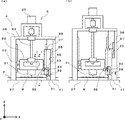
塗布装置の概略図を図6に示す。塗布装置1は、基板Wを搬送する搬送部2と、基板に塗布液を塗布する塗布部3を有している。塗布部3は、搬送部2による基板Wの搬送方向と垂直な方向に伸びたスリットを有する口金を備え、基板Wを所定速度で搬送しながらこのスリットから塗布液を吐出し、基板W上に塗布膜を形成する。
この塗布膜の厚みを均一にするためには、スリットから吐出する塗布液の量を均一にするとともに、口金の高さをたとえばミクロン単位で精度良く制御し、口金と基板Wとの距離を均一に保つ必要がある。
この口金の高さを精度良く制御するための手段として、たとえば、下記特許文献1に示すような、直動装置にスケールを組込み、スケールから得られる位置情報をもとに位置決め対象の位置制御を行う手法が塗布装置の塗布部の構成に従来より用いられている。たとえば、図7(a)に示すように、口金91を搭載するビーム92が昇降して口金91の高さを制御する塗布部90において、直動ガイド95を介してビーム92を支持する支持部96にスケール93が取付けられ、ビーム92に読取ヘッド94が取付けられている。ここで、読取ヘッド94がスケール93の目盛りを読み取り、その値をもとに読取ヘッド94の位置を制御することで、ビーム92および口金91の高さの制御を行い、口金91と基板Wとの距離を一定に保っている。また、スケール93は、スケール93の両端部の近傍の固定部97および固定部98にて、ボルト固定によりベース部96に取付けられている。
しかし、上記特許文献1に記載された直動装置では、周囲温度に変化があると、正確に位置制御ができなくなるおそれがあるいう問題があった。
たとえば、図7(a)に示す塗布部90の支持部96が熱膨張し、図7(b)の状態になったとすると、支持部96の膨張に応じて、図7(a)で示していた固定部97および固定部98の位置も変化し、固定部97’および固定部98’が示す位置へ変位する。このとき、固定部97と固定部98との間の距離にくらべ、固定部97’と固定部98’との間の距離は長くなるため、スケール93は引き伸ばされ、スケール93の目盛り間隔も広がってしまう。
ここで、たとえばスケール93のAという座標の目盛りを読取ヘッド94が読み取った位置において口金91が基板Wに塗布液の塗布動作を行う、というように制御していた場合、図7(a)の場合と図7(b)の場合とで、スケール93が座標Aを示す位置は異なってしまう。すなわち、口金91の位置を正確に制御することができなくなり、口金91と基板Wとの距離を均一に保って均一な膜厚で塗布することが困難になっていた。
なお、この問題を防ぐ一つの方法として、支持部96を低熱膨張材で構成させることが挙げられるのだが、一般に支持部96を構成させる材料として用いられるSUSなどと比較して低熱膨張材は非常にコストが高く、また、支持部96は口金91を支持する部材であり、大きな形状を有するため、低熱膨張材におきかえることは塗布装置の製作コストの大幅増につながる。そのため、可能な限り予算を抑えて塗布装置を製作する場合、この方法を採用するのは難しい。
上記課題を解決するために本発明のスケール装置は、一方向に目盛りが配列されたスケールと、前記スケールを取付けるベース部と、前記スケールの目盛りを読み取る読取ヘッドと、を備えるスケール装置であり、前記スケールは、目盛りが付された方向である目盛り方向の一端において前記ベース部に固定される固定部と、反対側の端部において直動ガイドを介して前記ベース部に取付けられるガイド取付け部とで前記ベース部に取付けられており、前記直動ガイドが動く方向と前記目盛り方向とが同一であることを特徴としている。
上記スケール装置によれば、スケールが目盛り方向の一端においてベース部に固定される固定部と、反対側の端部において直動ガイドを介してベース部に取付けられるガイド取付け部とでベース部に取付けられており、直動ガイドが動く方向と目盛り方向とが同一であることより、ベース部が熱膨張もしくは収縮しても、それに応じて直動ガイドが動作することで、目盛り方向にスケールが伸縮することを防ぐことができるため、スケールの座標精度を保ち、読取ヘッドをともなった精度の良い位置制御が可能である。
また、前記ベース部の片端が搭載部材に固定されている場合、前記目盛り方向に関して、前記固定部は、前記ガイド取付け部よりも前記搭載部材に近いと良い。
このようにベース部の片端が搭載部材に固定されている場合、ベース部が搭載部材に固定されている箇所がベース部の膨張の起点となる。そこで、目盛り方向に関して、固定部は、ガイド取付け部よりも搭載部材に近いことにより、ベース部の膨張の起点と固定部との距離を近くすることができるため、ベース部の熱膨張もしくは収縮による固定部の位置の変動を小さくし、スケールの位置が変動することを抑えることが可能である。
また、その他の形態として、一方向に目盛りが配列されたスケールと、前記スケールを取付けるブラケットと、前記ブラケットを取付けるベース部と、前記スケールの目盛りを読み取る読取ヘッドと、を備えるスケール装置であり、前記ブラケットは、前記スケールに目盛りが付された方向である目盛り方向の一端において前記ベース部に固定される第1の固定部と、反対側の端部において第1の直動ガイドを介して前記ベース部に取付けられる第1のガイド取付け部とで前記ベース部に取付けられており、前記スケールは、前記目盛り方向の一端において前記ブラケットに固定される第2の固定部で前記ブラケットに取付けられ、反対側の端部において第2の直動ガイドを介して前記ブラケットもしくは前記ベース部に取付けられる第2のガイド取付け部で前記ブラケットもしくは前記ベース部に取付けられており、前記第1の直動ガイドおよび前記第2の直動ガイドが動く方向と前記目盛り方向とが同一であり、前記目盛り方向に関して、前記第1の固定部と前記第1のガイド取付け部との位置関係と、前記第2の固定部と前記第2のガイド取付け部との位置関係が反対であることを特徴とすることもできる。
このように、第1の直動ガイドおよび第2の直動ガイドが動く方向と目盛り方向とが同一であることにより、ベース部の熱膨張もしくは収縮によってブラケットおよびスケールが伸縮させられることを防ぐことができる。さらに、目盛り方向に関して、第1の固定部と第1のガイド取付け部との位置関係と、第2の固定部と第2のガイド取付け部との位置関係が反対であることにより、ベース部およびブラケットと、スケールとで熱膨張もしくは収縮により変位する方向が反対となり、各々の膨張もしくは収縮による影響が相殺されるため、ベース部、ブラケット、およびスケールの伸縮から生じるスケールの座標誤差を小さくすることができ、読取ヘッドをともなった精度の良い位置制御が可能である。
また、前記ベース部の片端が搭載部材に固定されている場合、前記目盛り方向に関して、前記第1の固定部は、前記第1のガイド取付け部よりも前記搭載部材に近いようにすると良い。
このように、目盛り方向に関して、第1の固定部は、第1のガイド取付け部よりも搭載部材に近いことにより、ベース部の膨張の起点と第1の固定部との距離を近くすることができるため、ベース部の熱膨張もしくは収縮による第1の固定部の位置の変動を小さくし、スケールの位置が変動することを抑えることが可能である。
本発明のスケール装置によれば、使用環境の温度変化の影響を抑え、位置決め対象の正確な位置制御ができる。
本発明に係る実施の形態を図面を用いて説明する。なお、以降の説明では、先述した図6の塗布装置において基板Wが搬送される方向をX軸方向、水平面上でX軸方向と直交する方向をY軸方向とし、これらと直交する方向をZ軸方向とし、説明を進める。
本発明の一実施形態におけるスケール装置を図1に示す。図1(a)のスケール装置10は、スケール11、読取ヘッド12、直動ガイド13、およびベース部14を有しており、読取ヘッド12がスケール11から読み取った座標情報をもとに、読取ヘッド12とともに移動可能に組み付けられたユニットの位置制御を行う。
スケール11は、一方向に目盛りが配列された平板であり、本実施形態ではリニアスケールを用いている。スケール11は、光電式のリニアスケールなどのように目盛りが刻まれて配列されているものでも、電磁誘導式のリニアスケールのようにコイルが、もしくは磁気式のリニアスケールのようにN極およびS極が、目盛りの代わり配列されているものなどでも良い。なお、以降の説明では、目盛りまたはそれに代わるものが配列されている方向を目盛り方向と呼ぶ。
読取ヘッド12は、スケール11から座標を読み取る検出器であり、上述のスケール11の種類に対応したものが設けられている。また、読取ヘッド12は、目盛り方向に移動可能な、図示しない直動機構に取付けられており、その移動範囲内の各位置においてスケール11から座標を読み取ることが可能である。
直動ガイド13は、レール16とレール16に取付けられたスライダ17から構成されているユニットであり、スライダ17がレール16に沿って少ない摺動抵抗で往復動する。
ベース部14は、スケール11を取付ける部材であり、スケール11を取付けるための平面を有している。また、直動ガイド13も、このベース部14に取付けられており、スライダ17が目盛り方向に動作するような向きでレール16がベース部14に固定されている。また、ベース部14の外形は、スケール装置10の用途によって様々であり、鉛直方向に物体を直動させる機構の支柱であったり、水平方向に物体を直動させる機構の底板であったりしても良い。
スケール11は、片方の端部では、固定部15においてボルトなどによりベース部14に固定されている。また、反対側の端部では、ガイド取付け部18において直動ガイド13のスライダ17に取付けられている。すなわち、スケール11はその片端において直動ガイド13を介してベース部14に取付けられる形態をとっている。ここで、スケール11が歪むことなく取付けられるよう、ベース部14は直動ガイド13を収容する段差を有し、ベース部14の固定部15を有する面とスライダ17のスケール11を取付ける面とが面一となっている。
以上の構成をとることにより、ベース部14が周囲温度の変化などにより膨張もしくは収縮した場合でも、スケール11は、少なくとも目盛り方向にはこの膨張、収縮の影響を受けなくすることが可能である。
具体的には、ベース部14が膨張して図1(a)の状態から図1(b)の状態になり、それにあわせて直動ガイド13のレール16の位置が変化したとしても、スライダ17がレール16上を変位することで、スライダ17の位置はベース部14の膨張に影響されない。したがって、ベース部14が膨張もしくは収縮しても、それにともなって目盛り方向にスケール11が伸縮することを防ぐことができる。さらに、スケール11の熱膨張が無視できる場合、スケール11の長さおよび目盛り間隔は変動しない。
ここで、スケール11の厚さが薄い場合、このスケール11を直接ベース部14およびスライダ17に取付けると、スケール11が曲がるおそれがある。その場合は、図示しないブロックを中間に設け、スケール11をこのブロックに固定して補強した後、このブロックをベース部14およびスライダ17に取付けても良い。このとき、ブロックを低熱膨張材で形成することにより、このブロック自身が温度変化で膨張もしくは収縮してスケール11を伸縮させることを防ぐことができる。
図2は、本実施形態のスケール装置10を用いた一例である。スケール装置10は、塗布装置の塗布部3において口金を昇降させる機構の位置制御に用いられている。
図2(a)に示した塗布部3は、先述のスケール装置10および口金昇降部4を有しており、口金昇降部4は口金21、ビーム22、モータ23、ボールねじ24、直動ガイド25および支持部26を有している。
口金21は、下向きに開口してY軸方向にのびたスリットを有し、口金21の下方を搬送部2によりX軸方向に搬送される基板Wに帯状に塗布液を塗布する。
ビーム22は、口金21を支持し、自身が移動することで口金21が移動することを可能とする、Y軸方向にのびた梁である。ビーム22には直動ガイド25のスライダが取付けられており、直動ガイド25を介して支持部26に接続されている。ここで、直動ガイド25のレールは、口金21およびビーム22が移動するべき方向に沿って支持部26に配置、固定されており、今回の例では、Z軸方向に配置されている。
ビーム22のY軸方向の両端部にはボールねじ24が取付けられており、また、各ボールねじ24にはモータ23が取付けられており、外部制御によって各モータ23が動作することにより各ボールねじ24が回転し、ビーム22および口金21が直動ガイド25のレールの向きに沿ってZ軸方向に移動する。
支持部26は、ビーム22のY軸方向の両端部に設けられ、前述の通り直動ガイド25を介してビーム22と接続し、また、モータ23およびボールねじ24を支持することにより、ビーム22および口金21を支持している。また、支持部26は、端部28において搭載部材である定盤27に搭載、固定されている。この支持部26は、安価で剛性を確保できるSUSで形成されることが多い。
ここで、スケール装置10は目盛り方向を口金21が変位する方向、すなわちZ軸方向にとり、塗布部3に組み込まれている。
ベース部14は、口金昇降部4の支持部26の一部であり、目盛り方向がZ軸方向となるようにスケール11が固定部15において固定され、また、スライダの移動方向がZ軸方向となるように直動ガイド13が取付けられている。
読取ヘッド12は、口金昇降部4のビーム22に取付けられ、ビーム22および口金21とともにZ軸方向に移動可能である。
以上の構成をとることにより、ベース部14すなわち支持部26が周囲温度の変化などにより膨張し、図2(a)から図2(b)の状態となった場合でも、先述の通り、スケール11は、少なくとも目盛り方向にはこの膨張の影響を受けなくすることができ、スケール11の座標精度を保ち、読取ヘッド12をともなった精度の良い位置制御が可能である。また、ベース部14およびスケール11が収縮する場合でも同様である。
なお、図2(b)では、説明を簡略にするため、ベース部14の膨張はZ軸方向のみのものを示している。
一方、この場合、ベース部14は定盤27への搭載部である端部28を起点として、上方向に膨張するため、固定部15の位置は変動する。すなわち、図2(a)の状態では端部28と固定部15までの距離がdであったものに対し、ベース部14が膨張して固定部15は図2(b)に示すように固定部15’の位置へ変位し、端部28との距離がd’になったとすると、これらの差の(d’-d)だけスケール11の取付け位置が上昇する。ここで、たとえばスケール11のAという座標の目盛りを読取ヘッド12が読み取った位置において口金21が基板Wに塗布液の塗布動作を行う、というように制御していた場合、図2(a)の場合と図2(b)の場合とで、スケール11が座標Aを示す位置は(d’-d)だけ異なり、本実施形態のスケール装置10によりベース部14の膨張で目盛り方向にスケール11が伸長することを防ぐことができても、わずかながら、この差は生じることとなる。
この差を極小にするために、固定部15を端部28に近づけて距離d自身を短くし、距離dと距離d’との差を小さくすると良い。少なくとも、固定部15が直動ガイド13よりも目盛り方向に関して端部28に近い配置になるようスケール11を取付けることにより、固定部15が直動ガイド13よりも端部28に遠い配置でスケール11を取付けた場合に比べて距離dを短くすることができる。
次に、本発明の他の実施形態を図3に示す。
図3(a)のスケール装置30は、スケール31、読取ヘッド32、ブラケット33、直動ガイド34、直動ガイド35、およびベース部36を有している。
図3(a)のスケール装置30は、スケール31、読取ヘッド32、ブラケット33、直動ガイド34、直動ガイド35、およびベース部36を有している。
スケール31は、先述のスケール11と同様に光電式、電磁誘導式、もしくは磁気式などのリニアスケールであり、これらリニアスケールの、目盛りまたはそれに代わるものが配列されている方向を目盛り方向と呼ぶ。
読取ヘッド32は、スケール31から座標を読み取る検出器であり、上述のスケール31の種類に対応したものが設けられている。また、読取ヘッド32は、目盛り方向に移動可能な、図示しない直動機構に取付けられており、その移動範囲内の各位置においてスケール31から座標を読み取ることが可能である。
ブラケット33は、スケール31を取付ける部材であり、スケール31を取付けるための平面を有している。また、直動ガイド34も、このブラケット33に取付けられており、直動ガイド34のスライダが目盛り方向に動作するような向きで直動ガイド34のレールがブラケット33に固定されている。また、スケール31は、片方の端部では固定部37においてボルトなどにより固定され、反対側の端部ではガイド取付け部38において直動ガイド34のスライダに取付けられている。ここで、スケール31が歪むことなく取付けられるよう、ブラケット33は直動ガイド34を収容する段差を有し、ブラケット33の固定部37を有する面と直動ガイド34のスライダのスケール31を取付ける面とが面一となっている。
ベース部36は、上記のブラケット33を取付ける部材であり、ブラケット33を取付けるための平面を有している。また、直動ガイド35も、このベース部36に取付けられており、直動ガイド35のスライダが目盛り方向に動作するような向きで直動ガイド35のレールがベース部36に固定されている。また、ブラケット33は、片方の端部では固定部39においてボルトなどにより固定され、反対側の端部では、ガイド取付け部40において直動ガイド35のスライダに取付けられている。すなわち、ブラケット33はその片端において直動ガイド35を介してベース部36に接続されている形態をとっている。ここで、ベース部36は直動ガイド35を収容する段差を有し、ベース部36の固定部39を有する面と直動ガイド35のスライダのブラケット33を取付ける面とが面一となっている。
ここで、目盛り方向に関して、固定部37とガイド取付け部38との位置関係と、固定部39とガイド取付け部40との位置関係とは反対になっている。すなわち、図3(a)においてブラケット33が左側の端部に固定部39を有してベース部36に固定され、右側の端部にガイド取付け部40を有して直動ガイド35に取付けられているならば、スケール31は右側の端部において固定部37を有してブラケット33に固定され、左側の端部にガイド取付け部38を有して直動ガイド35に取付けられている。
以上の構成をとることにより、図3(a)のベース部36が周囲温度の変化などにより膨張し、図3(b)の状態になった場合でも、ブラケット33およびスケール31は、少なくとも目盛り方向にはこの膨張の影響を受けなくすることが可能である。さらに、スケール31の熱膨張も考慮した場合に、ガイド取付け部40よりも固定部39に近い方の端部41を起点とすれば、ベース部36の膨張によって固定部39が変位する方向およびブラケット33が固定部39を起点として膨張することによって固定部37が変位する方向と、スケール31が固定部37を起点として膨張することによってスケール31の目盛りが変位する方向とが反対となり、各々の変位が相殺される。そのため、スケール31、ブラケット33、およびベース部36の膨張から生じるスケールの座標誤差を小さくすることができる。また、スケール31、ブラケット33、およびベース部36が収縮する場合でも同様である。
また、ブラケット33は低熱膨張材で形成すると良い。スケール31は既製品を使用するため、また、ベース部36は形状が大きく、装置製作コストが大幅に増加するため、これらを低熱膨張材におきかえることは困難であるが、少なくともブラケット33を低熱膨張材で形成することにより、ブラケット33の熱膨張の影響でスケール31の位置が変化することを抑えることができる。
この実施形態のスケール装置30を用いた一例を図4に示す。
図4(a)に示した塗布部3は、先述のスケール装置30および口金昇降部4を有しており、口金昇降部4の構成は、図2と同様である。
スケール装置30は目盛り方向を口金21が変位する方向、すなわちZ軸方向にとり、塗布部3に組み込まれている。
ベース部36は、口金昇降部4の支持部26の一部であり、端部41において搭載部材である定盤27に搭載、固定されている。また、目盛り方向がZ軸方向となるようにスケール31がブラケット33に固定部37において固定され、このブラケット33がベース部36に固定部39において固定されている。また、直動ガイド34および直動ガイド35はスライダの移動方向がともにZ軸方向となるように取付けられており、固定部39はガイド取付け部40よりも目盛り方向に関して端部41の近傍、すなわち下方に配置され、固定部37はガイド取付け部38よりも上方に配置されている。
読取ヘッド32は、口金昇降部4のビーム22に取付けられ、ビーム22および口金21とともにZ軸方向に移動可能である。
以上の構成をとることにより、スケール31、ブラケット33、およびベース部36が周囲温度の変化などにより膨張して図4(a)から図4(b)の状態となり、図4(a)の固定部37および固定部39が図4(b)の固定部37’および固定部39’のように変位した場合でも、先述の通り、スケール31の目盛りが変位する方向は両固定部が変位する方向と反対となるため、それぞれの膨張の影響を相殺することができる。そのため、スケール31の座標誤差を小さくし、読取ヘッド12をともなった精度の良い位置制御が可能である。また、ベース部14およびスケール11が収縮する場合でも同様である。
なお、図4(b)でも、説明を簡略にするため、ベース部36の膨張はZ軸方向のみのものを示している。
ここで、スケール31の所定の座標においてさらに位置決め精度を高くするためには、その座標においてスケール31、ブラケット33、およびベース部36の熱膨張の影響が少なくなるように固定部37および固定部39の位置を設定し、スケール装置30を形成すれば良い。この一例として、図4においてスケール31のAという座標を読取ヘッド32が読み取った位置において口金21が基板Wに塗布液の塗布動作を行う、というように制御する場合で説明する。このとき、座標Aの位置精度が特に重要であるとする。
スケール31の熱膨張率がα1、ブラケット33の熱膨張率がα2、ベース部36の熱膨張率がα3であったとし、図4(a)の状態から周囲温度がΔtだけ変化して、図4(b)の状態になったとする。このとき、図4(a)において搭載面28から固定部39までの目盛り方向の距離がd1であったとすると、これは搭載面28を起点とし、ベース部36の熱膨張によって変化するため、図4(a)の状態から図4(b)の状態になったときのこの距離の変化量Δd1は、以下の式(1)の通りとなり、固定部39は搭載面28より上方にあるため、上方向に変位する。
Δd1=α1×Δt×d1 ……(1)
また、図4(a)において固定部39から固定部37までの目盛り方向の距離がd2であったとすると、これは固定部39を起点とし、ブラケット33の熱膨張によって変化するため、図4(a)の状態から図4(b)の状態になったときのこの距離の変化量Δd2は、以下の式(2)の通りとなり、固定部37は固定部39より上方にあるため、これも上方向に変位する。
Δd2=α2×Δt×d2 ……(2)
また、図4(a)において固定部37から座標Aの目盛りまでの目盛り方向の距離がd3であったとすると、これは固定部37を起点とし、スケール31の熱膨張によって変化するため、図4(a)の状態から図4(b)の状態になったときのこの距離の変化量Δd3は、以下の式(3)の通りとなり、スケール31の目盛りは固定部37より下方にあるため、これは下方向に変位する。
Δd3=α3×Δt×d3 ……(3)
これらより、図4(a)の状態から図4(b)の状態になったときの座標Aの目盛りの目盛り方向の位置の変化量Δdは、変位の方向を考慮して式(1)から式(3)を合わせた以下の式(4)の通りとなる。
Δd=(α1×d1+α2×d2-α3×d3)×Δt ……(4)
したがって、(α1×d1+α2×d2-α3×d3)の値が小さくなるようにd1、d2、およびd3の距離を設定し、スケール装置30の構成に反映させることにより、座標Aの目盛りの位置精度を高めることが可能である。
Δd1=α1×Δt×d1 ……(1)
また、図4(a)において固定部39から固定部37までの目盛り方向の距離がd2であったとすると、これは固定部39を起点とし、ブラケット33の熱膨張によって変化するため、図4(a)の状態から図4(b)の状態になったときのこの距離の変化量Δd2は、以下の式(2)の通りとなり、固定部37は固定部39より上方にあるため、これも上方向に変位する。
Δd2=α2×Δt×d2 ……(2)
また、図4(a)において固定部37から座標Aの目盛りまでの目盛り方向の距離がd3であったとすると、これは固定部37を起点とし、スケール31の熱膨張によって変化するため、図4(a)の状態から図4(b)の状態になったときのこの距離の変化量Δd3は、以下の式(3)の通りとなり、スケール31の目盛りは固定部37より下方にあるため、これは下方向に変位する。
Δd3=α3×Δt×d3 ……(3)
これらより、図4(a)の状態から図4(b)の状態になったときの座標Aの目盛りの目盛り方向の位置の変化量Δdは、変位の方向を考慮して式(1)から式(3)を合わせた以下の式(4)の通りとなる。
Δd=(α1×d1+α2×d2-α3×d3)×Δt ……(4)
したがって、(α1×d1+α2×d2-α3×d3)の値が小さくなるようにd1、d2、およびd3の距離を設定し、スケール装置30の構成に反映させることにより、座標Aの目盛りの位置精度を高めることが可能である。
また、スケール装置30の構成について、図3では、直動ガイド34はスケール31とブラケット33との間に設け、スケール31がブラケット33およびベース部36の熱膨張の影響を受けないようにしているが、図5に示すように直動ガイド34をスケール31とベース部36との間に設けても良い。このような配置であっても、スケール31がブラケット33およびベース部36の熱膨張の影響を受けないという効果を得ることができるためである。
以上説明したスケール装置により、使用環境の温度変化の影響を抑え、位置決め対象の正確な位置制御が可能である。
また、上述の説明では、スケールが取付けられているベース部は、口金やビームを支持する支持部の一部としていたが、必ずしも支持部の一部である必要は無く、この支持部と独立して設けても構わない。
また、本発明のスケール装置は、上述のような塗布装置の口金位置制御だけでなく、たとえばXYステージなど、スケールを用いて精密位置決めを行う全ての直動機構に適用可能である。
1 塗布装置
2 搬送部
3 塗布部
4 口金昇降部
10 スケール装置
11 スケール
12 読取ヘッド
13 直動ガイド
14 ベース部
15 固定部
15’ 固定部
16 レール
17 スライダ
18 ガイド取付け部
21 口金
22 ビーム
23 モータ
24 ボールねじ
25 直動ガイド
26 支持部
27 定盤
28 端部
30 スケール装置
31 スケール
32 読取ヘッド
33 ブラケット
34 直動ガイド
35 直動ガイド
36 ベース部
37 固定部
37’ 固定部
38 ガイド取付け部
39 固定部
39’ 固定部
40 ガイド取付け部
41 端部
90 塗布部
91 口金
92 ビーム
93 スケール
94 読取ユニット
95 直動ガイド
96 支持部
97 固定部
97’ 固定部
98 固定部
98’ 固定部
W 基板
2 搬送部
3 塗布部
4 口金昇降部
10 スケール装置
11 スケール
12 読取ヘッド
13 直動ガイド
14 ベース部
15 固定部
15’ 固定部
16 レール
17 スライダ
18 ガイド取付け部
21 口金
22 ビーム
23 モータ
24 ボールねじ
25 直動ガイド
26 支持部
27 定盤
28 端部
30 スケール装置
31 スケール
32 読取ヘッド
33 ブラケット
34 直動ガイド
35 直動ガイド
36 ベース部
37 固定部
37’ 固定部
38 ガイド取付け部
39 固定部
39’ 固定部
40 ガイド取付け部
41 端部
90 塗布部
91 口金
92 ビーム
93 スケール
94 読取ユニット
95 直動ガイド
96 支持部
97 固定部
97’ 固定部
98 固定部
98’ 固定部
W 基板
Claims (4)
- 一方向に目盛りが配列されたスケールと、
前記スケールを取付けるベース部と、
前記スケールの目盛りを読み取る読取ヘッドと、
を備えるスケール装置であり、
前記スケールは、目盛りが付された方向である目盛り方向の一端において前記ベース部に固定される固定部と、反対側の端部において直動ガイドを介して前記ベース部に取付けられるガイド取付け部とで前記ベース部に取付けられており、前記直動ガイドが動く方向と前記目盛り方向とが同一であることを特徴とする、スケール装置。 - 前記ベース部の片端が搭載部材に固定されている場合、前記目盛り方向に関して、前記固定部は、前記ガイド取付け部よりも前記搭載部材に近いことを特徴とする、請求項1に記載のスケール装置。
- 一方向に目盛りが配列されたスケールと、
前記スケールを取付けるブラケットと、
前記ブラケットを取付けるベース部と、
前記スケールの目盛りを読み取る読取ヘッドと、
を備えるスケール装置であり、
前記ブラケットは、前記スケールに目盛りが付された方向である目盛り方向の一端において前記ベース部に固定される第1の固定部と、反対側の端部において第1の直動ガイドを介して前記ベース部に取付けられる第1のガイド取付け部とで前記ベース部に取付けられており、
前記スケールは、前記目盛り方向の一端において前記ブラケットに固定される第2の固定部で前記ブラケットに取付けられ、反対側の端部において第2の直動ガイドを介して前記ブラケットもしくは前記ベース部に取付けられる第2のガイド取付け部で前記ブラケットもしくは前記ベース部に取付けられており、
前記第1の直動ガイドおよび前記第2の直動ガイドが動く方向と前記目盛り方向とが同一であり、
前記目盛り方向に関して、前記第1の固定部と前記第1のガイド取付け部との位置関係と、前記第2の固定部と前記第2のガイド取付け部との位置関係が反対であることを特徴とする、スケール装置。 - 前記ベース部の片端が搭載部材に固定されている場合、前記目盛り方向に関して、前記第1の固定部は、前記第1のガイド取付け部よりも前記搭載部材に近いことを特徴とする、請求項3に記載のスケール装置。
Applications Claiming Priority (2)
| Application Number | Priority Date | Filing Date | Title |
|---|---|---|---|
| JP2011207121A JP2013068508A (ja) | 2011-09-22 | 2011-09-22 | スケール装置 |
| JP2011-207121 | 2011-09-22 |
Publications (1)
| Publication Number | Publication Date |
|---|---|
| WO2013042563A1 true WO2013042563A1 (ja) | 2013-03-28 |
Family
ID=47914336
Family Applications (1)
| Application Number | Title | Priority Date | Filing Date |
|---|---|---|---|
| PCT/JP2012/073014 Ceased WO2013042563A1 (ja) | 2011-09-22 | 2012-09-10 | スケール装置 |
Country Status (3)
| Country | Link |
|---|---|
| JP (1) | JP2013068508A (ja) |
| TW (1) | TW201313381A (ja) |
| WO (1) | WO2013042563A1 (ja) |
Families Citing this family (2)
| Publication number | Priority date | Publication date | Assignee | Title |
|---|---|---|---|---|
| JP6107390B2 (ja) * | 2013-04-30 | 2017-04-05 | 株式会社ニコン | 撮像装置 |
| KR102489221B1 (ko) * | 2020-12-21 | 2023-01-17 | 세메스 주식회사 | 위치 측정기 및 이를 포함하는 기판 처리 장치 |
Citations (4)
| Publication number | Priority date | Publication date | Assignee | Title |
|---|---|---|---|---|
| JPS63317711A (ja) * | 1987-06-11 | 1988-12-26 | ドクトル・ヨハネス・ハイデンハイン・ゲゼルシヤフト・ミト・ベシユレンクテル・ハフツング | 位置測定装置 |
| JP2001021303A (ja) * | 1999-07-09 | 2001-01-26 | Mitsutoyo Corp | 変位測定方法及びシステム |
| JP2001050776A (ja) * | 1999-08-12 | 2001-02-23 | Sony Precision Technology Inc | スケールユニットの連結部材 |
| JP2004058218A (ja) * | 2002-07-30 | 2004-02-26 | Ricoh Microelectronics Co Ltd | 位置決め装置、処理装置及び位置決め方法 |
Family Cites Families (4)
| Publication number | Priority date | Publication date | Assignee | Title |
|---|---|---|---|---|
| US5270886A (en) * | 1989-08-07 | 1993-12-14 | Antek Peripherals, Inc. | Two motor servo system for a removable disk drive |
| JP2000097686A (ja) * | 1998-09-25 | 2000-04-07 | Nikon Corp | 測長装置 |
| JP2009019876A (ja) * | 2005-10-28 | 2009-01-29 | Mitsubishi Electric Corp | 光学式絶対値エンコーダ |
| JP2009180525A (ja) * | 2008-01-29 | 2009-08-13 | Mitsutoyo Corp | 測定装置 |
-
2011
- 2011-09-22 JP JP2011207121A patent/JP2013068508A/ja not_active Withdrawn
-
2012
- 2012-09-04 TW TW101132172A patent/TW201313381A/zh not_active IP Right Cessation
- 2012-09-10 WO PCT/JP2012/073014 patent/WO2013042563A1/ja not_active Ceased
Patent Citations (4)
| Publication number | Priority date | Publication date | Assignee | Title |
|---|---|---|---|---|
| JPS63317711A (ja) * | 1987-06-11 | 1988-12-26 | ドクトル・ヨハネス・ハイデンハイン・ゲゼルシヤフト・ミト・ベシユレンクテル・ハフツング | 位置測定装置 |
| JP2001021303A (ja) * | 1999-07-09 | 2001-01-26 | Mitsutoyo Corp | 変位測定方法及びシステム |
| JP2001050776A (ja) * | 1999-08-12 | 2001-02-23 | Sony Precision Technology Inc | スケールユニットの連結部材 |
| JP2004058218A (ja) * | 2002-07-30 | 2004-02-26 | Ricoh Microelectronics Co Ltd | 位置決め装置、処理装置及び位置決め方法 |
Also Published As
| Publication number | Publication date |
|---|---|
| JP2013068508A (ja) | 2013-04-18 |
| TWI560023B (ja) | 2016-12-01 |
| TW201313381A (zh) | 2013-04-01 |
Similar Documents
| Publication | Publication Date | Title |
|---|---|---|
| US11469125B2 (en) | Device and method for linearly moving first and second moving bodies relative to target object | |
| KR101831375B1 (ko) | 기판 이동을 위한 위치 설정 장치 | |
| KR102676391B1 (ko) | 노광 장치, 노광 방법, 플랫 패널 디스플레이의 제조 방법, 및 디바이스 제조 방법 | |
| CN112423991A (zh) | 打印头调节装置、系统和方法 | |
| TWI501058B (zh) | 用以改善站台移動時間之方法、系統及設備 | |
| JP2005128783A (ja) | ステージ装置 | |
| JP2021050374A (ja) | 成膜装置および成膜方法、情報取得装置、アライメント方法、ならびに電子デバイスの製造装置および製造方法 | |
| US11410866B2 (en) | Apparatus and method for linearly moving movable body relative to object | |
| WO2013042563A1 (ja) | スケール装置 | |
| KR20170137253A (ko) | 위치 조절 장치 및 이를 구비한 페이스트 디스펜서 | |
| KR102472753B1 (ko) | 이동체 장치, 이동 방법, 노광 장치, 노광 방법, 플랫 패널 디스플레이의 제조 방법, 그리고 디바이스 제조 방법 | |
| KR20190080755A (ko) | 제어 방법, 제어 장치, 리소그래피 장치, 및 물품의 제조 방법 | |
| JPS5972135A (ja) | 超精密xy移動装置 | |
| JP4962779B2 (ja) | ステージ装置およびその浮上制御方法と、ステージ装置を用いた露光装置 | |
| WO2001091534A1 (fr) | Dispositif de montage de puces et procede d'alignement associe | |
| JP4717639B2 (ja) | 基板の両面形状測定方法及び装置 | |
| KR102478705B1 (ko) | 이동체 장치, 이동 방법, 노광 장치, 노광 방법, 플랫 패널 디스플레이의 제조 방법, 그리고 디바이스 제조 방법 | |
| JP4962780B2 (ja) | ステージ装置およびその浮上制御方法と、ステージ装置を用いた露光装置 | |
| CN108020995B (zh) | 光刻机水平向测量装置及方法 | |
| JP2002094295A (ja) | 電子部品搭載機 | |
| JP2009016679A (ja) | ステージ装置およびその浮上制御方法と、ステージ装置を用いた露光装置 | |
| KR102321780B1 (ko) | 결정 방법, 광학 장치, 투영 광학계, 노광 장치 및 물품의 제조 방법 | |
| KR20250136740A (ko) | 정렬 장치, 성막 장치 및 성막 방법 | |
| JP2017022242A (ja) | インプリント装置および物品製造方法 | |
| CN120368851A (zh) | 一种工件台系统误差的校正系统及校正方法 |
Legal Events
| Date | Code | Title | Description |
|---|---|---|---|
| 121 | Ep: the epo has been informed by wipo that ep was designated in this application |
Ref document number: 12833443 Country of ref document: EP Kind code of ref document: A1 |
|
| NENP | Non-entry into the national phase |
Ref country code: DE |
|
| 122 | Ep: pct application non-entry in european phase |
Ref document number: 12833443 Country of ref document: EP Kind code of ref document: A1 |