WO2013042366A1 - Dispositif d'entretien pour tête d'éjection de liquide, dispositif d'éjection de liquide et imprimante - Google Patents
Dispositif d'entretien pour tête d'éjection de liquide, dispositif d'éjection de liquide et imprimante Download PDFInfo
- Publication number
- WO2013042366A1 WO2013042366A1 PCT/JP2012/005982 JP2012005982W WO2013042366A1 WO 2013042366 A1 WO2013042366 A1 WO 2013042366A1 JP 2012005982 W JP2012005982 W JP 2012005982W WO 2013042366 A1 WO2013042366 A1 WO 2013042366A1
- Authority
- WO
- WIPO (PCT)
- Prior art keywords
- wiper
- cap
- nozzle surface
- ink
- unit
- Prior art date
Links
Images


Classifications
-
- B—PERFORMING OPERATIONS; TRANSPORTING
- B41—PRINTING; LINING MACHINES; TYPEWRITERS; STAMPS
- B41J—TYPEWRITERS; SELECTIVE PRINTING MECHANISMS, i.e. MECHANISMS PRINTING OTHERWISE THAN FROM A FORME; CORRECTION OF TYPOGRAPHICAL ERRORS
- B41J2/00—Typewriters or selective printing mechanisms characterised by the printing or marking process for which they are designed
- B41J2/005—Typewriters or selective printing mechanisms characterised by the printing or marking process for which they are designed characterised by bringing liquid or particles selectively into contact with a printing material
- B41J2/01—Ink jet
- B41J2/135—Nozzles
- B41J2/165—Preventing or detecting of nozzle clogging, e.g. cleaning, capping or moistening for nozzles
- B41J2/16517—Cleaning of print head nozzles
- B41J2/1652—Cleaning of print head nozzles by driving a fluid through the nozzles to the outside thereof, e.g. by applying pressure to the inside or vacuum at the outside of the print head
- B41J2/16532—Cleaning of print head nozzles by driving a fluid through the nozzles to the outside thereof, e.g. by applying pressure to the inside or vacuum at the outside of the print head by applying vacuum only
-
- B—PERFORMING OPERATIONS; TRANSPORTING
- B41—PRINTING; LINING MACHINES; TYPEWRITERS; STAMPS
- B41J—TYPEWRITERS; SELECTIVE PRINTING MECHANISMS, i.e. MECHANISMS PRINTING OTHERWISE THAN FROM A FORME; CORRECTION OF TYPOGRAPHICAL ERRORS
- B41J2/00—Typewriters or selective printing mechanisms characterised by the printing or marking process for which they are designed
- B41J2/005—Typewriters or selective printing mechanisms characterised by the printing or marking process for which they are designed characterised by bringing liquid or particles selectively into contact with a printing material
- B41J2/01—Ink jet
- B41J2/135—Nozzles
- B41J2/165—Preventing or detecting of nozzle clogging, e.g. cleaning, capping or moistening for nozzles
- B41J2/16517—Cleaning of print head nozzles
- B41J2/16535—Cleaning of print head nozzles using wiping constructions
- B41J2/16544—Constructions for the positioning of wipers
-
- B—PERFORMING OPERATIONS; TRANSPORTING
- B41—PRINTING; LINING MACHINES; TYPEWRITERS; STAMPS
- B41J—TYPEWRITERS; SELECTIVE PRINTING MECHANISMS, i.e. MECHANISMS PRINTING OTHERWISE THAN FROM A FORME; CORRECTION OF TYPOGRAPHICAL ERRORS
- B41J2/00—Typewriters or selective printing mechanisms characterised by the printing or marking process for which they are designed
- B41J2/005—Typewriters or selective printing mechanisms characterised by the printing or marking process for which they are designed characterised by bringing liquid or particles selectively into contact with a printing material
- B41J2/01—Ink jet
- B41J2/135—Nozzles
- B41J2/165—Preventing or detecting of nozzle clogging, e.g. cleaning, capping or moistening for nozzles
- B41J2/16505—Caps, spittoons or covers for cleaning or preventing drying out
-
- B—PERFORMING OPERATIONS; TRANSPORTING
- B41—PRINTING; LINING MACHINES; TYPEWRITERS; STAMPS
- B41J—TYPEWRITERS; SELECTIVE PRINTING MECHANISMS, i.e. MECHANISMS PRINTING OTHERWISE THAN FROM A FORME; CORRECTION OF TYPOGRAPHICAL ERRORS
- B41J2/00—Typewriters or selective printing mechanisms characterised by the printing or marking process for which they are designed
- B41J2/005—Typewriters or selective printing mechanisms characterised by the printing or marking process for which they are designed characterised by bringing liquid or particles selectively into contact with a printing material
- B41J2/01—Ink jet
- B41J2/135—Nozzles
- B41J2/165—Preventing or detecting of nozzle clogging, e.g. cleaning, capping or moistening for nozzles
- B41J2/16517—Cleaning of print head nozzles
- B41J2/16535—Cleaning of print head nozzles using wiping constructions
- B41J2/16538—Cleaning of print head nozzles using wiping constructions with brushes or wiper blades perpendicular to the nozzle plate
-
- B—PERFORMING OPERATIONS; TRANSPORTING
- B41—PRINTING; LINING MACHINES; TYPEWRITERS; STAMPS
- B41J—TYPEWRITERS; SELECTIVE PRINTING MECHANISMS, i.e. MECHANISMS PRINTING OTHERWISE THAN FROM A FORME; CORRECTION OF TYPOGRAPHICAL ERRORS
- B41J2/00—Typewriters or selective printing mechanisms characterised by the printing or marking process for which they are designed
- B41J2/005—Typewriters or selective printing mechanisms characterised by the printing or marking process for which they are designed characterised by bringing liquid or particles selectively into contact with a printing material
- B41J2/01—Ink jet
- B41J2/135—Nozzles
- B41J2/165—Preventing or detecting of nozzle clogging, e.g. cleaning, capping or moistening for nozzles
- B41J2/16517—Cleaning of print head nozzles
- B41J2/16535—Cleaning of print head nozzles using wiping constructions
- B41J2/16544—Constructions for the positioning of wipers
- B41J2/16547—Constructions for the positioning of wipers the wipers and caps or spittoons being on the same movable support
-
- B—PERFORMING OPERATIONS; TRANSPORTING
- B41—PRINTING; LINING MACHINES; TYPEWRITERS; STAMPS
- B41J—TYPEWRITERS; SELECTIVE PRINTING MECHANISMS, i.e. MECHANISMS PRINTING OTHERWISE THAN FROM A FORME; CORRECTION OF TYPOGRAPHICAL ERRORS
- B41J2/00—Typewriters or selective printing mechanisms characterised by the printing or marking process for which they are designed
- B41J2/005—Typewriters or selective printing mechanisms characterised by the printing or marking process for which they are designed characterised by bringing liquid or particles selectively into contact with a printing material
- B41J2/01—Ink jet
- B41J2/135—Nozzles
- B41J2/165—Preventing or detecting of nozzle clogging, e.g. cleaning, capping or moistening for nozzles
- B41J2/16585—Preventing or detecting of nozzle clogging, e.g. cleaning, capping or moistening for nozzles for paper-width or non-reciprocating print heads
-
- B—PERFORMING OPERATIONS; TRANSPORTING
- B41—PRINTING; LINING MACHINES; TYPEWRITERS; STAMPS
- B41J—TYPEWRITERS; SELECTIVE PRINTING MECHANISMS, i.e. MECHANISMS PRINTING OTHERWISE THAN FROM A FORME; CORRECTION OF TYPOGRAPHICAL ERRORS
- B41J23/00—Power drives for actions or mechanisms
- B41J23/02—Mechanical power drives
- B41J23/025—Mechanical power drives using a single or common power source for two or more functions
Definitions
- the present invention relates to a liquid jet head maintenance apparatus for performing maintenance such as nozzle clogging prevention and foreign matter adhesion prevention of a liquid jet head mounted on a liquid jet apparatus such as a printer, and liquid jet such as a printer provided with the maintenance apparatus. It relates to the device.
- the liquid ejecting apparatus ejects droplets from the nozzle of the droplet ejecting head to perform dispensing, application, printing, and the like of the liquid.
- the liquid ejecting apparatus is provided with a maintenance apparatus for the droplet ejecting head.
- An inkjet printer is known as a liquid ejecting apparatus.
- the inkjet printer is provided with a maintenance device for an inkjet head which is a liquid jet head.
- the maintenance device performs the maintenance operation of the ink jet head between standby and printing in order to keep the nozzle surface of the ink jet head in good condition all the time.
- the maintenance operation of the maintenance device includes, as is well known, capping of the nozzle surface, suction of ink from a cap or ink nozzle, wiping of the nozzle surface, and the like.
- the capping is an operation of covering the nozzle surface of the inkjet head in the printing standby state with a cap to seal the nozzle surface. It is possible to prevent the occurrence of nozzle clogging and the like when the ink of the ink nozzle (liquid ejection nozzle) provided on the nozzle surface is dried.
- the ink suction is an operation of driving the suction pump in a state where the nozzle face of the ink jet head is covered, and sucking and discharging the ink in the nozzle or the ink in the cap.
- Wiping is an operation of wiping away ink (liquid) adhering to the nozzle surface of the ink jet head, or foreign matter such as paper powder or dust with a wiper.
- Such maintenance devices are disclosed in Patent Documents 1 to 5.
- the maintenance devices disclosed in Patent Documents 3 and 4 can perform the selective wiping and the selective suction operation on a plurality of nozzle rows.
- JP 2007-276304 A JP, 2011-104979, A JP, 2001-30507, A JP, 2009-45898, A Patent No. 3155871 gazette
- a liquid jet head composed of a plurality of head units is known.
- a line-type inkjet head consisting of a plurality of head units is known.
- the nozzle rows of the plurality of head units form a nozzle row having a length that encompasses the print width of the print medium.
- the maintenance device of the line type inkjet head may be disposed at a position out of the printing position by the inkjet head.
- the inkjet head is moved from the printing position to a position facing the maintenance device, and stopped at this position.
- the respective units on the maintenance device side are operated with respect to the stopped ink jet head, and maintenance operations such as nozzle capping, ink suction, and wiping are performed.
- the maintenance device is required to perform a plurality of maintenance operations on the inkjet head in the stopped state.
- the drive mechanism for performing the maintenance operation is complicated, and the device size is likely to increase. For this reason, there is a strong demand for downsizing and downsizing of the drive mechanism of the maintenance device.
- the power transmission path from one power source is switched according to the rotation angle position of the cylindrical cam or the intermittent gear, using components for power transmission such as a cylindrical cam or an intermittent gear.
- the power transmission mechanism using the cylindrical cam and the intermittent gear is complicated in configuration, and the setting change can not be simplified when changing the switching timing of the power.
- the liquid jet head maintenance device of the present invention is A cap for capping the nozzle surface of the liquid jet head; A wiper for wiping the nozzle surface; A suction pump for suctioning ink from the cap; A cap drive transmission mechanism for moving the cap relative to the nozzle surface; A wiper / pump drive transmission mechanism for moving the wiper and driving the suction pump; A drive switching mechanism that switches the drive of the wiper-pump drive transmission mechanism to the drive of the suction pump or the movement of the wiper according to the movement position of the cap; It is characterized by having.
- Driving of the ink suction pump may be performed after the cap is put on the nozzle surface.
- Driving of the wiper may be performed after the cap is separated from the nozzle surface. Therefore, based on the movement position of the cap, the drive switching mechanism can appropriately switch the wiper and pump drive transmission mechanism. It is possible to switch one of the suction pump and the wiper to a drivable state based on the moving position of the linearly reciprocating cap, without using a cylindrical cam, an intermittent gear, or the like. The management and change of the start point and the end point of the suction operation and the wiping operation can be easily performed.
- the drive switching mechanism can be configured as follows using a planetary gear reducer. That is, the drive switching mechanism has a drive motor for rotating a drive shaft, and an internal gear or planet carrier, and reduces the rotation of the drive shaft of the drive motor to rotate the internal gear or planet carrier. And a latch mechanism for stopping rotation of the internal gear of the planetary gear reducer or the planetary carrier according to the movement position of the cap.
- the maintenance device of the present invention is provided with a wiper support structure of the following configuration in order to be able to keep the wiping pressure of the wiper constant.
- the maintenance device A wiper frame supporting and moving the wiper; An apparatus frame supporting the wiper frame; An elastic member disposed on the device frame and supporting the wiper frame; A cap support member that supports the cap and is moved by the cap drive transmission mechanism; An engagement portion disposed on the wiper frame and engaged with the cap support member to move the wiper frame with the cap support member; Have.
- the wiper frame is supported by the device frame in a movable state by an elastic member. Therefore, the wiper frame is attached to the apparatus frame in a floating state by the elastic force of the elastic member.
- the wiper frame in a floating state with respect to the apparatus frame is pressed against the nozzle surface of the liquid jet head or the surface of the carriage on which the liquid jet head is mounted. Even when the wiper frame is inclined with respect to the nozzle surface of the liquid jet head, the wiper frame is corrected to a posture parallel to the nozzle surface. Thus, the wiper frame is pressed against the nozzle surface in parallel with the nozzle surface.
- the gap between the wiper mounted on the wiper frame and the nozzle surface is maintained at a predetermined distance.
- the tip end of the wiper is pressed against the nozzle surface with a predetermined force.
- the wiping pressure of the wiper is stabilized, the fluctuation of the wiping state at each portion of the wiper tip edge is reduced, and the wiping performance is enhanced.
- the liquid jet head may be composed of a plurality of head units.
- a plurality of wipers for wiping each of the nozzle faces of the plurality of head units are mounted on the wiper frame.
- the wiper frame is elongated in the wiper movement direction, that is, in the direction of the nozzle row of the nozzle surface.
- the wiper frame is inclined in the wiper movement direction, the distance between the wiper and the nozzle surface changes during wiping.
- the nozzle surface can not be wiped with a constant wiping pressure. In such a case, it is effective to use a wiper frame in a floating state with respect to the device frame.
- the maintenance device of the present invention is configured as follows so that movement of the cap and the wiper can be used to select a plurality of wipers for wiping the nozzle surface.
- the maintenance device of the present invention is The wiper is disposed at a first position in the moving direction, and when the wiper frame moves in a direction away from the nozzle surface, the wiper engages with the wiper to move the wiper from the first state to the first state A first wiper engagement member switching to a second state different from The wiper is disposed at a second position different from the first position in the moving direction, and when moved in a direction away from the nozzle surface, the wiper is engaged with the wiper to move the wiper from the first state to the first position.
- a second wiper engagement member switching to a second state different from the state of 1 The wiper is disposed at a third position different from the first position and the second position in the moving direction, and engages the wiper and the second wiper when the wiper moves to the third position.
- the wiper With the wiper in the first position, when the wiper frame moves in the direction away from the nozzle surface, the wiper engages with the first wiper engaging member, and the first state (for example, the falling state) to the second state Switch to (for example, standing up). With the wiper in the second position, when the wiper frame moves away from the nozzle surface, the second wiper switches from the first state to the second state. Therefore, it is possible to selectively switch the state of both wipers to selectively wipe the nozzle faces at different positions. That is, a wiper for wiping the nozzle surface can be selected. Further, by moving the first and second wipers in the second state to the third position, they can be returned to the first state (for example, the fallen state).
- the maintenance device of the present invention has a second cap for capping the nozzle surface at a position different from the nozzle surface for capping by the cap, and the cap support member supports the cap and the second cap.
- the cap support member may support a first cap pressing member pressing the cap against the nozzle surface and a second cap pressing member pressing the second cap against the nozzle surface. desirable. This configuration is advantageous when closely spaced multiple caps.
- the maintenance device of the present invention is configured as follows so that the suction of ink from a plurality of caps capping the nozzle surface can be selectively performed by using the movement of the cap and the wiper.
- the maintenance device of the present invention is A first ink suction path for moving the ink sucked by the cap; A second ink suction path for moving the ink sucked by the second cap; A first valve for opening and closing the first ink suction path; A second valve disposed at different positions in the moving direction of the first valve and the wiper to open and close the second ink suction path; A valve selector that moves in a moving direction of the wiper and moves to a position facing the first valve or a position facing the second valve to open and close the first valve or the second valve; Have.
- the selection operation of the valve performing the selective suction operation is realized by the movement of the cap and the movement of the wiper. Therefore, the selective suction operation can be realized by a compact and compact mechanism without using a component for selective switching such as a cylindrical cam, an intermittent gear or a swinging member.
- the wiper of the maintenance device of the present invention has a convex curved surface, has a concave curved surface in contact with the convex curved surface of the wiper, and includes a wiper cleaner for cleaning the convex curved surface of the wiper.
- the second wiper When the second wiper is provided, the second wiper has a convex curved surface, and the wiper cleaner has a concave curved surface in contact with the convex curved surface of the second wiper.
- the maintenance device of the present invention has a wiper cleaner elastic support member disposed on the wiper frame and supporting the wiper cleaner.
- the maintenance device of the present invention prevents the scattering of the ink from the wiper at the end of the wiping.
- the maintenance device according to the present invention drives the wiper and pump drive transmission mechanism to wipe the nozzle surface with the wiper, and then drives the cap drive transmission mechanism to drive the wiper from the nozzle surface. It has a control part which makes it separate.
- the wiper In wiping the nozzle surface, the wiper is pressed against the nozzle surface.
- the wiper in this state moves parallel to the nozzle surface by the wiper-pump drive transmission mechanism to wipe the nozzle surface.
- the wiper is pressed against the nozzle surface and is in an elastically deformed state.
- the cap drive transmission mechanism causes the wiper in this state to move away from the nozzle surface at the time after the end of wiping.
- the wiper When the wiper is separated from the nozzle surface, it is desirable that the wiper after wiping is separated from the nozzle surface in an oblique direction.
- the direction in which the wiper is separated from the nozzle surface is appropriately set in accordance with the bending direction of the tip end of the wiper in a state where the wiper is pressed against the nozzle surface. Thereby, when the wiper is separated from the nozzle surface, it is possible to prevent the ink liquid and the like from scattering as much as possible.
- the leading edge of the wiper pressed against the nozzle surface is generally bent in the direction opposite to the wiping direction.
- the direction in which the wiper is separated from the nozzle surface is set to be inclined to the side opposite to the wiping direction with respect to the direction perpendicular to the nozzle surface.
- the liquid injection device of the present invention is A liquid ejecting head having a nozzle surface on which a nozzle for ejecting ink is disposed; A cap for capping a nozzle surface of the liquid jet head, and a maintenance unit having a wiper for wiping the nozzle surface; A suction pump for suctioning ink from the cap; A cap drive transmission mechanism for moving the cap relative to the nozzle surface; A wiper / pump drive transmission mechanism for moving the wiper and driving the suction pump; A drive switching mechanism that switches the drive of the wiper-pump drive transmission mechanism to the drive of the suction pump or the movement of the wiper according to the movement position of the cap; Equipped with
- the printer of the present invention is An ink jet head having a nozzle surface for disposing a nozzle for discharging ink and discharging ink onto a recording medium; A cap for capping the nozzle surface of the inkjet head, and a maintenance unit having a wiper for wiping the nozzle surface; A suction pump for suctioning ink from the cap; A cap drive transmission mechanism for moving the cap relative to the nozzle surface; A wiper / pump drive transmission mechanism for moving the wiper and driving the suction pump; A drive switching mechanism that switches the drive of the wiper-pump drive transmission mechanism to the drive of the suction pump or the movement of the wiper according to the movement position of the cap; A transport path for transporting the recording medium; A transport mechanism that transports the recording medium along the transport path; Equipped with
- the "liquid ejecting apparatus” refers to an ink jet printer, copying machine that ejects ink from a liquid ejecting head such as a printing head to a material to be ejected such as recording paper to execute recording on recording paper etc.
- the present invention is not limited to facsimiles and the like, and includes a liquid ejecting apparatus that ejects or discharges a liquid other than ink, and also includes various liquid consuming apparatuses that eject or discharge small amounts of droplets.
- the “liquid” may be any material that can be ejected or discharged from the liquid ejecting apparatus.
- the substance may be in a liquid phase as long as the substance is in a liquid phase, and the liquid having high or low viscosity, sol, gel water, other inorganic solvents, organic solvents, solutions, liquid resin, liquid metal (metal melt Containing granular bodies such as).
- the liquid in one state of the substance, it also includes particles in which solid material functional materials such as pigments and metal particles are dissolved, dispersed or mixed in a solvent.
- the liquid include ink and liquid crystal.
- the ink includes various liquid compositions such as gel ink and hot melt ink as well as general aqueous ink and oil ink.
- the liquid ejecting apparatus include, for example, a liquid containing materials such as an electrode material and a coloring material used for manufacturing a liquid crystal display, an EL (electroluminescence) display, a surface emitting display, a color filter, etc. in the form of dispersion or dissolution. It may be a liquid ejecting apparatus that ejects, a liquid ejecting apparatus that ejects a bioorganic substance used for producing a biochip, a liquid ejecting apparatus that ejects a liquid to be a sample used as a precision pipette, a printing apparatus, a micro dispenser, or the like.
- a transparent resin liquid such as an ultraviolet curable resin is used to form a liquid injection device that injects lubricating oil at precise points such as watches and cameras at pinpoints, micro hemispherical lenses (optical lenses) used for optical communication elements, etc. It may be a liquid ejecting apparatus that ejects onto a substrate, or a liquid ejecting apparatus that ejects an etching solution such as an acid or an alkali to etch a substrate or the like.
- FIG. 1 is a longitudinal sectional view showing an entire configuration of a printer. It is explanatory drawing of an inkjet head and a carriage. It is explanatory drawing of an inkjet head and a carriage. It is explanatory drawing which shows the movement path
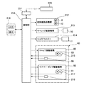
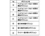
- FIG. 2 is a schematic block diagram of a control system of the printer. It is an explanatory view showing a list of cap positions in a cap movement direction. It is explanatory drawing which shows the wiper position of the wiper movement direction. It is explanatory drawing which shows the wiper position of the wiper movement direction. It is explanatory drawing which shows the list of the wiper position of a wiper movement direction. It is explanatory drawing which shows a wiper raising position. It is explanatory drawing which shows the list of wiper raising positions. It is an explanatory view showing a wiping start position. It is an explanatory view showing a wiping start position. It is an explanatory view showing a list of wiping start positions.
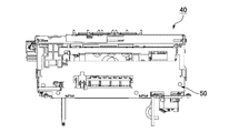
- FIG. 1 is a longitudinal sectional view showing the entire configuration of the ink jet printer according to the present embodiment.
- the inkjet printer 1 (hereinafter sometimes referred to simply as the “printer 1”) is provided with a roll paper loading unit 2, and the roll paper loading unit 2 takes up the long recording paper P in a roll shape.
- the roll paper 3 of the above configuration is loaded.
- a recording paper transport path 5 is formed from the roll paper loading unit 2 to the paper discharge port 4 formed on the front of the printer.
- a delivery roller 6, a sheet guide 7, a transport roller pair 8, and a platen 9 are disposed from the upstream side to the downstream side in the recording sheet transport direction. Further, the inkjet head 11 mounted on the head carriage 10 is disposed. The head carriage 10 moves the nozzle surface 11 a of the inkjet head 11 to the printing position of the recording paper conveyance path 5 facing the platen 9 and the home position deviated from the recording conveyance path 5. A maintenance device 40 described later is disposed at the home position.
- the transport roller pair 8 includes a drive roller 8a and a driven roller 8b.
- the drive roller 8 a is rotationally driven in the forward and reverse directions by the paper feed motor 12.
- Ink is supplied to the ink jet head 11 from an ink cartridge 14 mounted in the ink cartridge mounting portion 13.
- ink cartridge 14 mounted in the ink cartridge mounting portion 13.
- four color inks of black, cyan, magenta, and yellow are supplied to the inkjet head 11.
- the inkjet head 11 is a line-type inkjet head.
- the recording paper P fed from the roll paper 3 loaded in the roll paper loading unit 2 is transported along the recording paper transport path 5. Printing is performed by the inkjet head 11 on the recording paper P conveyed on the platen 9. The recording paper P after printing is discharged forward from the paper discharge port 4 on the front of the printer.
- FIG. 2A is an explanatory view showing the positional relationship between the printing position of the inkjet head 11 and the home position when the printer 1 is viewed from above
- FIG. 2B is the printing position and home position when the printer 1 is viewed from the front It is explanatory drawing which shows the positional relationship of.
- the inkjet head 11 is a line-type inkjet head composed of a plurality of inkjet heads.
- the first head 11A and the second head 11B are provided.
- Each ink nozzle row of the first and second heads 11A and 11B has a length capable of covering the width direction of the printing area of the recording paper P (the width in the direction orthogonal to the conveyance direction of the recording paper P).
- the first and second heads 11A and 11B of the line-type inkjet head are mounted on the carriage 10 with their nozzle faces 11a facing downward.
- the carriage 10 is horizontal, the nozzle surface 11 a is horizontal downward.
- a platen gap G having a preset size is formed.
- a maintenance device 40 is disposed on the side of the platen 9.
- the carriage 10 moves the ink jet head 11 to a printing position A facing the platen 9 and a home position B completely away from the recording paper conveyance path 5 (a position shown by a dashed dotted line in FIGS. 2A and 2B).
- the nozzle surface 11 a of the inkjet head 11 faces the maintenance device 40.
- the inkjet head 11 is in a horizontally oriented posture in which the longitudinal direction is directed in a direction perpendicular to the conveyance direction of the recording paper P. In this state, the ink nozzle row of each color provided in the first and second heads 11A and 11B covers the width direction of the printing area of the recording paper P.
- the inkjet head 11 is turned by 90 degrees from the attitude at the printing position A, and is in the attitude directed to the direction. That is, the ink jet head 11 has a vertically oriented posture in which the longitudinal direction thereof matches the transport direction.
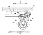
- FIG. 3 is an explanatory view showing a movement locus of the carriage 10 on which the ink jet head 11 is mounted.
- the printer 1 positions and stops the inkjet head 11 at the printing position A, and performs printing on the recording paper P by performing an ink discharge operation every time the recording paper P is transported in this state by a predetermined pitch.
- the printer 1 retracts the ink jet head 11 to the home position B which is separated from the top of the platen 9 and stands by at the home position B.
- the maintenance device 40 While the inkjet head 11 is waiting, the maintenance device 40 performs a maintenance operation to prevent or eliminate clogging of the ink nozzles of the inkjet head 11.
- the maintenance device 40 lifts a cap provided at the upper end thereof to cap the nozzle surface 11 a.
- the ink discharge operation (flushing) is performed from the ink nozzles of the ink jet head 11 into the cap of the maintenance device 40.
- the maintenance device 40 performs an operation of sucking the ink from the cap.
- the maintenance device 40 is provided with a wiper for wiping the nozzle surface 11 a. When resuming printing, the ink jet head 11 is moved to the printing position A after the cap and the wiper retract downward.
- FIG. 4 is an explanatory view showing the nozzle surface 11 a of the ink jet head 11.
- the first head 11A includes four head units 1-1 to 1-4 including black and cyan ink nozzle arrays.
- the four head units 1-1 to 1-4 are arranged in two rows of two each along the direction of the ink nozzle row. Between each row, the head units 1-1 to 1-4 are arranged in a staggered manner.
- the second head 11B includes four head units 2-1 to 2-4 provided with yellow and magenta ink nozzle arrays.
- the four head units 2-1 to 2-4 are arranged in two rows of two each along the direction of the ink nozzle row. Between each row, the head units 2-1 to 2-4 are arranged in a staggered manner.
- the cap arrangement state of the maintenance device 40 described later is set to correspond to the arrangement state of the eight head units 1-1 to 1-4 and 2-1 to 2-4.
- the nozzle surfaces 1-1a to 1-4a of the head units 1-1 to 1-4 and the nozzle surfaces 2-1a to 2-4a of the head units 2-1 to 2-4 are head cover surfaces, respectively. It is surrounded by 10b.
- the head cover surface 10 b is surrounded by the lower surface portion 10 of the carriage 10.
- the nozzle surface 11a of the inkjet head 11 is a generic name of these nozzle surfaces 1-1a to 1-4a and 2-1a to 2-4a.
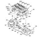
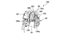
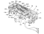
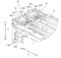
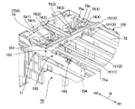
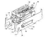
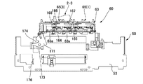
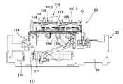
- FIG. 5A is a perspective view showing the maintenance device 40 taken out and FIG. 5B is a side view thereof.
- FIG. 6 is an exploded perspective view showing the main part of the maintenance device 40.
- the capping direction V the moving direction of the cap for capping the nozzle surfaces 1-1a to 1-4a
- the capping direction V1 the direction in which the cap approaches the nozzle surface
- the capping release direction V2 reverse The direction in which the cap moves away from the nozzle surface.
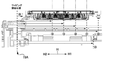
- the moving direction of the wiper for wiping the nozzle surfaces 1-a to 1-4a is referred to as a wiper moving direction H, and in the wiping movement direction H, the moving direction for the wiper when wiping the nozzle surface is a wiping direction H2
- the direction H2), the direction opposite to the wiping direction, is called H1 (wiper advancing direction H1).
- the maintenance device 40 has a rectangular parallelepiped shape as a whole, and includes an apparatus frame 50, a cap unit 60, a wiper unit 70, an ink suction pump 94, a cap drive transmission mechanism 80, and a wiper / pump drive transmission mechanism 90. ing. A cap unit 60, an ink suction pump 94, a cap drive transmission mechanism 80, and a wiper pump drive transmission mechanism 90 are assembled to the apparatus frame 50.
- the apparatus frame 50 includes a rectangular bottom plate 51, and side plates 52 and 53 and end plates 54 and 55 which are respectively erected from the long side edge and the short side edge on both sides of the bottom plate 51.
- Two guide posts 56 a and 56 b are vertically attached to the bottom plate 51 of the device frame 50.
- the cap unit 60 is movable along the guide posts 56a, 56b.
- the cap drive transmission mechanism 80 moves the cap unit 60 in the direction along the guide posts 56a and 56b, that is, in the cap movement direction V (the capping direction V1 and the capping removal direction V2).
- the cap unit 60 has a number (eight) of caps 64 (1) to 64 (4), 65 (1) to 65 (8) corresponding to the head units 1-1 to 1-4 and 2-1 to 2-4. 4) is installed.
- the nozzle surfaces 1-1a to 1-4a of the head units 1-1 to 1-4 and 2-1 to 2-4 by the caps 64 (1) to 64 (4), 65 (1) to 65 (4), 2-1a to 2-4a (see FIG. 4) are capped.
- the ink suction pump 94 sucks the ink from each of the caps 64 (1) to 64 (4) and 65 (1) to 65 (4). Therefore, the ink is sucked from the ink nozzles of the head units 1-1 to 1-4 and 2-1 to 2-4 in the capping state.
- the suctioned ink is collected, for example, in a waste ink tank (not shown) provided in the ink cartridge 14.
- the wiper unit 70 includes four wipers 75 (not shown) that wipe the nozzle surfaces 1-1a to 1-4a and 2-1a to 2-4a of the head units 1-1 to 1-4 and 2-1 to 2-4. 1) to 75 (4) are installed.
- the wiper 75 (1) wipes the nozzle surfaces 1-1a, 1-3a of the head units 1-1, 1-3, and the wiper 75 (2) is the nozzle surface 1- of the head units 1-2, 1-4.
- the wiper 75 (3) wipes the nozzle surfaces 2-1a and 2-3a of the head units 2-1 and 2-3, and the wiper 75 (4) wipes the head unit 2-2, Wiping 2-4 nozzle faces 2-2a and 2-4a.
- the wipers 75 (1) to 75 (4) reciprocate in the wiper movement direction H which is a direction along the long side direction of the maintenance device 40.
- the wiper movement direction H is a direction parallel to the ink nozzle row of the inkjet head 11 located at the home position B.
- the wiper pump drive transmission mechanism 90 includes a drive motor 91 for driving the wiper unit 70 and the ink suction pump 94.
- the wiper and pump drive transmission mechanism 90 is provided with a drive switching mechanism 100 (see FIG. 8A).
- the drive switching mechanism 100 operates the wiper and pump drive transmission mechanism 90 according to the movement position of the cap unit 60 and accordingly the movement positions of the caps 64 (1) to 64 (4) and 65 (1) to 65 (4). , Switching the wiper to either the movable state or the driveable state of the suction pump.
- the cap unit 60 includes a cap frame 61, and first and second cap bases 62 and 63 (cap support members) fixed to the cap frame 61. .
- caps 64 (1) to 64 (4) are mounted on the first cap base 62, and four caps 65 (1) to 65 (4) are mounted on the second cap base 63.
- caps 64 (1) to 64 (4) will be referred to as “caps 64” and the caps 65 (1) to 65 (4) will be referred to as “caps 65”.
- the caps 64 (1) to 64 (4) have the same shape, and the nozzle surfaces 1-1a to 1-4a and 2-1a to 2 of the head units 1-1 to 1-4 and 2-1 to 2-4. And-provided with an elongated rectangular contour lip (cap opening edge) capable of concealing 4a.
- the caps 64 (1), 64 (3) are arranged at regular intervals along their length.
- the caps 64 (2), 64 (4) are also arranged at regular intervals along their length.
- the caps 64 (1) and 64 (3) constituting one cap row and the caps 64 (2) and 64 (4) constituting the other cap row are mutually arranged in a staggered manner. It is done.
- Each of the caps 64 (1) to 64 (4) is supported by the first cap base 62 via a pair of spring members 62a (cap pressing members), for example, a pair of compression coil springs (see FIG. 18A, which will be described later). See FIG. 22A).
- the pair of spring members 62 a is disposed between the end portions on both sides in the longitudinal direction of each of the caps 64 (1) to 64 (4) and the bottom plate portion of the first cap base 62.
- the caps 65 (1) to 65 (4) mounted on the second cap base 63 have the same shape as the caps 64 (1) to 64 (4), and are arranged in the same arrangement as these. .
- Each of the caps 65 (1) to 65 (4) is supported by the second cap base 63 via a pair of spring members 63a (cap pressing members), for example, a pair of compression coil springs.
- the pair of spring members 63a are disposed at both ends in the lengthwise direction of the respective caps 65 (1) to 65 (4).
- the caps 64 (1) to 64 (4) cap the head units 1-1 to 1-4 of the first head 11A of the ink jet head 11 shown in FIG.
- the caps 65 (1) to 65 (4) cap the head units 2-1 to 2-4 of the second head 11B shown in FIG.
- the cap diagonal peeling mechanism 160 is attached to the cap unit 60 (see FIGS. 18A to 18C and the like).
- the cap diagonal peeling mechanism 160 is provided for each of the caps 64 (1) to 64 (4) and 65 (1) to 65 (4) with the nozzle surface 1 of the head units 1-1 to 1-4 and 2-1 to 2-4.
- the lip surface end face of the cap opening edge
- the lip surface is inclined with respect to the nozzle surface.
- the wiper unit 70 includes a wiper frame 71 having a rectangular frame shape. At both ends in the short side direction of the wiper frame 71, a pair of guide shafts 72 is bridged in parallel in the long side direction of the wiper frame 71.
- the wiper holder unit 73 is disposed so as to be slidable along the pair of guide shafts 72.
- the wiper holder unit 73 is slidable along the guide shaft 72 from the home position 73A to the opposite end of the wiper unit 70.
- the wiper movement direction H is the movement direction of the wiper holder unit 73 defined by the guide shaft 72.
- wiper holders 74 (1) to 74 (4) are mounted in the wiper holder unit 73.
- One wiper 75 (1) to 75 (4) is mounted on each of the wiper holders 74 (1) to 74 (4).
- the wiper holders 74 (1) to 74 (4) will be referred to as “wiper holders 74" and the wipers 75 (1) to 75 (4) will be referred to as "wipers 75" as necessary.
- the wiper 75 (1) wipes the nozzle surfaces of the two head units 1-1 and 1-3 in the outer row of the first head 11 A shown in FIG.
- the wiper 75 (2) wipes the nozzle faces of the remaining two head units 1-2, 1-4.
- the wiper 75 (3) wipes the two head units 2-1, 2-3 in the inner row of the second head 11B shown in FIG.
- the wiper 75 (4) wipes the remaining two head units 2-2, 2-4.
- FIG. 7A and 7B show a cap drive transmission mechanism 80 for moving the cap unit 60.
- FIG. 7A is an exploded perspective view of the apparatus frame 50 with the side plates 52 and 53 omitted
- FIG. 7B is a perspective view of the apparatus frame 50 with the cap unit 60 assembled.
- the cap drive transmission mechanism 80 includes a pair of spiral cams 81 a and 81 b attached to the device frame 50.
- the spiral cams 81a and 81b are disposed adjacent to the guide posts 56a and 56b.
- the spiral cams 81 a and 81 b are supported by the bottom plate 51 so as to be rotatable around a central axis perpendicular to the bottom plate 51.
- Spiral grooves are formed on the outer peripheral surfaces of the spiral cams 81a and 81b along the direction of the central axis.
- the upward side surfaces of the spiral groove are cam surfaces 82a and 82b which extend in the vertical direction at a predetermined pitch in a spiral shape.
- a pair of cam follower rollers 66 (only one roller 66 is shown in the figure) is rotatably mounted on the cap frame 61 of the cap unit 60.
- the roller 66 rests on the cam surfaces 82a and 82b in a freely rolling manner.
- a guide hole 85 (only one guide hole 85 is shown in the figure) is formed.
- Guide posts 56a and 56b are slidably passed through the guide holes 85, respectively.
- a motor 83 is disposed at one end of the bottom plate 51 in the long side direction. Instead of the motor 83, a motor disposed on the main body side of the ink jet printer 1 can also be used as a drive source.
- the rotational force of the motor 83 is transmitted to the spiral cams 81a and 81b via a belt-pulley type power transmission mechanism 84.
- the respective spiral cams 81a, 81b rotate synchronously about their central axis.
- the pair of spiral cams 81a and 81b is rotated.
- the roller 66 on the cap unit 60 side which rests on the spiral cam surfaces 82a, 82b, rolls along the cam surfaces 82a, 82b.
- the cap unit 60 is guided by the pair of guide posts 56a and 56b, and moves in the cap moving direction V, in the vertical direction of the printer in this example.
- the respective caps 64 (1) to 64 (4), 65 (1 ) To 65 (4) are capped from the lower side on the nozzle surfaces of the head units 1-1 to 1-4 and 2-1 to 2-4 of the ink jet head 11.
- the position of the cap movement direction V of the cap unit 60 is controlled based on the output of the position detector 86.
- the position detector 86 is, for example, a photointerrupter, and is disposed adjacent to the motor 83.
- the cap frame 61 of the cap unit 60 is provided with a detection piece 86 a.
- the output of the position detector 86 is switched. Based on this output, it can be seen that the cap unit 60 has reached the standby position.
- the position of the cap unit 60 can be controlled based on the output of the position detector 86 and the number of encoder pulses of a rotary encoder (not shown) built in the motor 83. That is, the positions of the caps 64 (1) to 64 (4) and 65 (1) to 65 (4) in the cap movement direction V can be known.
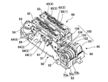
- FIG. 8A is a perspective view showing the wiper pump drive transmission mechanism 90 and the cap unit 60 assembled to the device frame 50, and a portion of the wiper pump drive transmission mechanism 90 and the side plates 52, 53 of the device frame 50. Is omitted.
- 8B and 8C are perspective views showing the wiper pump drive transmission mechanism 90, respectively.
- FIG. 8D is a skeleton diagram of the main part of the wiper-pump drive transmission mechanism 90
- FIGS. 8E and 8F are explanatory diagrams showing the operation of the drive switching mechanism 100.
- FIG. 9A is a perspective view showing a state in which the wiper and pump drive transmission mechanism 90 and the cap unit 60 are assembled to the device frame 50, and the side plates 52 and 53 of the device frame 50 are omitted.
- 9B and 9C are explanatory diagrams showing a power transmission path to the wiper side.
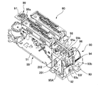
- FIG. 10 is a perspective view showing a state in which the wiper and pump drive transmission mechanism 90 and the cap unit 60 are assembled to the apparatus frame 50.
- the side plates 52 and 53 of the device frame 50 are omitted, and the wiper holder unit 73 of the wiper unit 70 is attached to the wiper and pump drive transmission mechanism 90.
- the wiper pump drive transmission mechanism 90 includes a drive motor 91 attached to the bottom plate 51 as shown in FIGS. 8A to 8D.
- a motor mounted on the main body side of the ink jet printer 1 can also be used as a drive source.
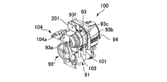
- the rotation of the drive motor 91 is transmitted to the input shaft 93 a of the planetary gear reducer 93 via the transmission gear train 92.
- the planetary gear reducer 93 includes a sun gear 93d (see FIG. 8D) coaxially connected to or integrally formed with the input shaft 93a, a planetary gear 93e (see FIG. 8D) engaged with the sun gear 93d, and a planetary gear It includes an internal gear 93b meshing with 93e, and a planet carrier 93c rotatably supporting a planet gear 93e.
- an ink suction pump 94 is disposed coaxially.
- the rotation shaft (not shown) of the ink suction pump 94 is coaxially connected to the internal gear 93 b of the planetary gear reducer 93.
- the ink suction pump 94 is rotationally driven by the decelerated rotation taken out from the internal gear 93 b to perform the ink suction operation.
- a drive side external gear 93f is coaxially integrally formed on the planet carrier 93c.
- the drive side external gear 93f is connected to the drive side sprocket 96 for driving the belt via the transmission external gear 95a and the driven side external gear 95b.
- the drive side sprocket 96 is rotationally driven by the decelerating rotation taken out from the planet carrier 93 c.
- One longitudinal end of the wiper frame 71 of the wiper unit 70 is the home position 73 A of the wiper holder unit 73.
- the driven sprocket 97 is rotatably attached to the end of the wiper frame 71 on the home position 73A side.
- a drive belt 98 is stretched between the drive side sprocket 96 and the driven side sprocket 97.
- a slider 99 is fixed to the drive belt 98.
- an engagement hole 73a engaged with a protrusion 99a formed on the slider 99 is formed.
- the wiper holder unit 73 engaged with the slider 99 moves in the wiper moving direction H.
- the four wipers 75 (1) to 75 (4) mounted on the wiper holder unit 73 make head units 1-1 and 1-3, head units 1-2 and 1-4, and head unit 2-1, The nozzle surfaces of the head unit 2-3 and the head units 2-2 and 2-4 can be wiped respectively.
- the wiper drive transmission mechanism in the wiper pump drive transmission mechanism 90 will be described in more detail with reference to FIGS. 9A, 9B and 9C.
- the wiper drive transmission mechanism portion has a drive side external gear 93 f and a transmission external gear 95 a mounted on the apparatus frame 50, and a driven external gear 95 b mounted on the wiper frame 71.
- the transmission external gear 95a meshes with both the drive external gear 93f and the driven external gear 95b.
- the transmission external gear 95 a is rotatably supported by the tip of the revolving frame 201.
- the proximal end of the swing frame 201 is supported by the cover 90A of the wiper and pump drive transmission mechanism 90 so as to be able to swing around the central axis of the drive side external gear 93f. Therefore, the transmission external gear 95a can revolve around the central axis of the drive external gear 93f while maintaining the meshing state with the drive external gear 93f.
- a connecting plate 202 is bridged between the shaft portion of the transmission external gear 95a and the shaft portion of the driven external gear 95b. Therefore, the transmission external gear 95a and the driven external gear 95b are always held in mesh.
- the wiper unit 70 is supported by the device frame 50 so as to be movable in the cap movement direction V. In addition, it is pressed in the capping direction V1 by the tension coil spring 108b, and is in a floating state from the apparatus frame 50.
- the driven external gear 95b on the wiper frame 71 side also moves in the same direction.
- the transmission external gear 95a meshing with the driven external gear 95b maintains meshing with the driven external gear 95a as the driven external gear 95b moves.
- the power for moving the wiper can be transmitted from the side of the device frame 50 to the side of the wiper frame 71 regardless of the movement of the wiper frame 71. According to this configuration, it is not necessary to mount all the parts constituting the wiper drive transmission mechanism on the moving wiper frame 71, which is advantageous for reducing the weight of the wiper unit 70.
- the drive-side external gear 93f of the wiper drive transmission mechanism portion is stopped.
- the transmission gear 95a meshing with the drive side external gear 93f revolves around the central axis of the drive side external gear 93f while rotating. Therefore, the driven external gear 95b engaged with the transmission gear 95a also rotates.
- the wiper holder unit 73 mounted on the drive belt 98 slightly moves in the wiper movement direction H.
- the direction indicated by the arrow H2 is the wiping direction, but it moves slightly in the opposite direction H1.
- the wiper holder unit 73 is slightly moved in the direction opposite to the wiping direction H2. That is, the wipers 75 (1) to 75 (4) move slightly in the direction H1 opposite to the wiping direction H2.
- the wipers 75 (1) to 75 (4) moves in a direction slightly inclined to the direction H1 opposite to the wiping direction H2 with respect to the direction perpendicular to the nozzle surface. Such movement of the wiper can prevent foreign matter such as ink from the wiper from being scattered around as described later.
- the drive switching mechanism 100 is attached to the wiper and pump drive transmission mechanism 90, and it is possible to switch between the wiper drivable state and the pump drivable state.
- the drive switching mechanism 100 performs switching operation according to the movement position of the cap unit 60. Therefore, the switching operation is performed according to the movement position of the caps 64 (1) to 64 (4) and 65 (1) to 65 (4).
- the planetary gear reducer 93 When the cap unit 60 moves from the standby position by a predetermined amount in the capping direction V1, the planetary gear reducer 93 has a state in which the internal gear 93b is rotatable and the planetary carrier 93c can not rotate. In this state, the decelerated rotation is output from the internal gear 93b. Therefore, the suction pump 94 connected to the internal gear 93b is driven, and the ink suction operation from each of the caps 64 (1) to 64 (4) and 65 (1) to 65 (4) becomes possible.
- the planetary gear reducer 93 can not rotate the internal gear 93b.
- the planet carrier 93c is rotatable. In this state, the decelerating rotation is output from the planet carrier 93c.
- the wipers 75 (1) to 75 (4) mounted on the wiper holder unit 73 connected to the planet carrier 93c can be moved. Therefore, the wiping operation of the nozzle surfaces of the head units 1-1 to 1-4 and 2-1 to 2-4 becomes possible.
- the drive switching mechanism 100 includes a first latch mechanism 102 that latches the internal gear 93b in a non-rotatable state by the spring force of the first tension coil spring 101, and the second latch mechanism 102.
- the second latch mechanism 104 latches the planetary carrier 93 c in a non-rotatable state by the spring force of the tension coil spring 103.
- the first latch mechanism 102 includes a first latch lever 102a
- the second latch mechanism 104 is a second latch disposed at a position (position on the side of the capping direction V1) in the figure above the first latch lever 102a.
- the lever 104a is provided.
- the cap frame 61 of the cap unit 60 is provided with a first cam surface 105 which can be pushed against the spring force of the first latch lever 102a by the movement of the cap unit 60 at a position facing the first latch lever 102a. It is done.
- a second cam surface 106 is formed on the cap frame 61 at a portion facing the second latch lever 104a so that the second latch lever 104a can be pushed against the spring force by the movement of the cap unit 60.
- the first and second cam surfaces 105 and 106 are formed at different positions in the cap movement direction V.
- the first latch lever 102a When the first latch lever 102a is pushed against the spring force, the latch by the first latch mechanism 102 is released, and the internal gear 93b switches to a rotatable state.
- the second latch lever 104a Conversely, when the second latch lever 104a is pushed against the spring force, the latch by the second latch mechanism 104 is released, and the planet carrier 93c is switched to the rotatable state.
- the wiper / pump drive transmission mechanism 90 is switched by the drive switching mechanism 100 between the pump drive enable state and the wiper drive enable state according to the movement position of the cap unit 60 in the cap movement direction V.
- the switching timing etc. can be easily adjusted or changed by changing the engagement position of the latch lever and the cam surface in the cap moving direction V. Therefore, compared with the mechanism which switches a power transmission direction using members, such as a cylindrical cam and an intermittent gear, a small, compact and easy switching mechanism is realizable.
- the nozzle surface when the nozzle surface is long in the nozzle row direction, as in the case of a line-type inkjet head, the nozzle surface may not be wiped at a constant wiping pressure.
- the maintenance device may be inclined relative to the nozzle surface of the ink jet head in the nozzle row direction (wiper movement direction). In this case, the pressing force of the wiper against the nozzle surface fluctuates during wiping, and the nozzle surface of each head unit can not be wiped with a constant wiping pressure.
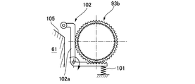
- the wiper unit 70 of this example is supported by the device frame 50 as follows.
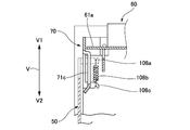
- FIG. 11A is a perspective view showing the cap unit 60 with the wiper unit 70 assembled.
- FIG. 11B is a partially enlarged perspective view showing a part of the side surface.
- FIG. 11C is an explanatory view showing the relationship between the device frame 50, the cap unit 60 and the wiper frame 71.
- the wiper unit 70 is supported by the device frame 50 in a state of being pulled up (pressed) by a spring force in the capping direction.
- guide portions 107a protruding in the capping direction V1 are formed at four corners of the device frame 50.
- the four corners of the wiper frame 71 of the wiper unit 70 are guide portions 107b which are guided in the cap movement direction V along the inner side surface of the guide portion 107a.
- a spring hook 108a is formed at the upper end edge of the guide portion 107a of the apparatus frame 50.
- One end of a tension coil spring 108b is hooked on each spring hook 108a.
- Spring hooks 108 c are formed at inner portions of the four corners of the wiper frame 71. The lower end of each tension coil spring 108b is hooked on the spring hook 108c.
- the wiper unit 70 is held movable relative to the apparatus frame 50 in the cap movement direction V. Further, it is attached to the apparatus frame 50 in a floating state by four tension coil springs 108b. That is, the wiper unit 70 is always pushed upward (in the capping direction) by the tension coil spring 108b, and it is possible to push the wiper unit 70 downward (in the capping release direction) against the spring force of the tension coil spring 108b.
- a restricting portion is provided between the device frame 50 and the wiper frame 71 of the wiper unit 70 to restrict the upper position of the wiper unit 70 (the position in the capping direction V1).
- the end plate 54 of the device frame 50 is formed with a pair of engagement protrusions 109a.
- the wiper frame 71 is formed with a pair of engagement frames 109b through which the respective engagement protrusions 109a are inserted.
- the other end plate 55 of the device frame 50 is also formed with an engagement protrusion 109c.
- the wiper frame 71 is formed with an engagement frame 109d into which the engagement protrusion 109c is inserted.
- the wiper unit 70 supported in a floating state on the device frame 50 moves with the cap unit 60 in a predetermined range in the cap movement direction V.
- the side plate portions 71b on both sides of the wiper frame 71 of the wiper unit 70 are formed with rectangular frame portions 71c set back to the inside.
- a pair of engaging protrusions 61a are formed to project laterally.
- the wiper unit 70 pulled up by the tension coil spring 108b does not move.
- the engagement protrusion 61a engages with the rectangular frame portion 71c. Thereafter, the wiper unit 70 is forced to move in the capping release direction V2 integrally with the cap unit 60.
- the wiper unit 70 moves in the capping direction together with the cap unit 60 by the spring force of the tension coil spring 108b.
- the engagement protrusion 61a of the cap unit 60 is separated from the rectangular frame portion 71c of the wiper frame 71 in the capping direction V1, as shown in FIG. 11B. Therefore, the wiper unit 70 is held at a predetermined position by the engagement between the engagement protrusions 109a and 109c and the engagement frames 109b and 109d by the spring force of the tension coil spring 108b.
- an abutting surface 71a is formed at a position one step higher along the long side edges on both sides thereof.
- the contact surface 71a is closer to the lip surface (end face of the cap opening edge) of the caps 64 (1) to 64 (4) and 65 (1) to 65 (4).
- the wiper unit 70 on which the wipers 75 (1) to 75 (4) are mounted is mounted on the apparatus frame 50 in a so-called floating state.
- the wiper unit 70 is disengaged from the cap unit 60 and is pressed in the capping direction V1 by the spring force of the tension coil spring 108b.
- the caps 64 (1) to 64 (4) and 65 (1) to 65 (4) of the cap unit 60 abut on the nozzle surface 11 a of the inkjet head 11
- the abutment surface 71 a of the wiper frame 71 of the wiper unit 70 Contact the lower surface of the carriage 10 on the side of the inkjet head 11.
- the wiper unit 70 is positioned with respect to the nozzle surface 11 a of the inkjet head 11. Even if the inkjet head 11 is inclined relative to the maintenance device 40, the wiper unit 70 follows the inclined attitude of the inkjet head 11.
- the plurality of wipers 75 (1) to 75 (4) mounted on the wiper unit 70 correspond to the nozzles of the head units 1-1 to 1-4 and 2-1 to 2-4 of the corresponding inkjet head 11. It is positioned at a fixed distance with respect to the surface.
- the wipers 75 (1) to 75 (4) can be pressed against the nozzle surfaces with a constant wiping pressure, and the nozzle surfaces can be reliably wiped in an appropriate pressing state. That is, in a state where the contact surface 71a of the wiper frame 71 contacts the lower surface of the carriage 10, the wipers 75 (1) to 75 (4) are raised to the upright position as described later. In this state, when the wipers 75 (1) to 75 (4) are moved in the wiping direction H2, the head units 1-1 to 1 constituting the ink jet head 11 have constant pressure at their leading edge portions. It becomes possible to press the nozzle surfaces 1-1a to 1-2a and 2-1a to 2-4a.
- a selective suction mechanism for selectively suctioning each of the plurality of caps 64 (1) to 64 (4), 65 (1) to 65 (4) individually using the suction pump 94.
- a selective suction mechanism is provided to selectively suction.
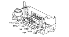
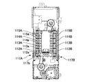
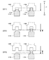
- FIGS. 12A to 12D are explanatory views showing a selective suction mechanism.
- a selective suction mechanism for selecting the caps 65 (1) to 65 (4) is disposed on the side of one side surface 52 of the device frame 50.
- a selective suction mechanism for selecting the caps 64 (1) to 64 (4) is disposed on the side of the other side surface 53. Since both selective suction mechanisms have basically the same configuration, the selective suction mechanism for selecting the caps 64 (1) to 64 (4) will be described.
- the suction tube 110 (see FIG. 11A) branched into four from the suction port and the side of the side plate 53 in the device frame 50 It communicates with the four valves 112A to 115A arranged in FIG.
- the valves 112A to 115A are, for example, normally closed valves that are always kept in a closed state by a built-in diaphragm (not shown).
- valves 112A to 115A are pushed in, the diaphragm is displaced and switched to the open state.
- the elastic return force of the diaphragm returns to the closed state again.
- the valves 112A to 115A are arranged along the wiper movement direction H.
- the valves 112A to 115A are opened, the ink suction passage for sucking the ink from the caps 64 (1) to 64 (4) is opened, and the ink suction pump 94 can suction ink.
- a guide shaft 116a extending in the wiper movement direction H is disposed along the upper edge of the window.
- a valve selector 117A is disposed slidably along the guide shaft 116a and a guide rail 116b defined by the lower edge of the window.
- the valve selector 117A is movable along the guide shaft 116a to a position facing the opening / closing levers 112a to 115a of the valves 112A to 115A.
- the valve selector 117A includes an engagement protrusion 117a protruding in the capping direction along the outer surface of the side plate 53, and a lever pushing protrusion 117b protruding inward of the side plate 53.
- a selector hook 118A protruding in the capping release direction V2 is attached on the side surface of the wiper holder unit 73 moving in the wiper movement direction H.
- the selector hook 118A is formed with an engagement recess 118a having a shape complementary to the engagement protrusion 117a.
- the engagement protrusion 117a of the valve selector 117A can be inserted into the engagement recess 118a in the capping direction.
- the wiper holder unit 73 can move the valve selector 117A in the wiper movement direction H along the guide shaft 116a.
- the selector hook 118A is positioned on the valve selector 117A.
- the cap unit 60 is moved in the capping release direction V2 by a predetermined amount.
- the wiper unit 70 also moves in the same direction, and the selector hook 118A of the wiper unit 70 engages with the valve selector 117A.
- the valve selector 117A is positioned in the wiper moving direction H with respect to one of the valves 112A to 115A.
- the opening / closing levers 112a to 115a of the valves 112A to 115A, in which the valve selector 117A is positioned, are held at the open position by the lever pushing projection 117b of the valve selector 117A. Therefore, the ink suction operation can be performed by the suction pump 94 from the corresponding caps 65 (1) to 65 (4) through the valves 112A to 115A held in the open state.
- the selection operation of the valves 112A to 115A for performing the selective suction operation can be realized by the movement of the cap unit 60 (cap) in the cap movement direction V and the movement of the wiper holder unit 73 (wiper) in the wiper movement direction H. Therefore, the selective suction operation can be realized with a small and compact configuration without using a component for selective switching such as a cylindrical cam, an intermittent gear, or a swing member.
- a valve full opening lever 119A is attached to the device frame 50.
- the valve full opening lever 119A can push in the opening and closing levers 112a to 115a of the valves 112A to 115A simultaneously.
- the valve selector 117A is positioned adjacent to the opening / closing lever 112a in the wiper movement direction H. In this position, the valve fully opening lever 119A is pushed in by the lever pushing projection 117b of the valve selector 117A.
- valve fully open lever 119A When the valve fully open lever 119A is pushed, the open / close levers 112a to 115a of the valves 112A to 115A are simultaneously pushed by the valve fully open lever 119A. Thereby, all the valves 112A to 115A are switched to the open state.
- the ink suction operation from all the caps 64 (1) to 64 (4) that is, the ink from the head units 1-1 to 1-4 capped by them Suction can be performed simultaneously.
- valve selector 117A When the valve selector 117A is positioned at a position deviated from the valves 112A to 115A and the valve full opening lever 119A, the valves 112A to 115A are held in a fully closed state.
- the lever pushing projection 117b interferes with the opening and closing levers 112a and 115a of the valves 112A to 115A.
- the cap unit 60 is formed with a lever pushing projection.
- the side plate portion 61 b of the cap frame 61 of the cap unit 60 is formed with a lever pushing protrusion 61 c that protrudes inward.
- the position of the lever pushing protrusion 61c is set as follows in the cap moving direction V.
- the lever pushing protrusion 61c reaches a position where the valve fully open lever 119A can be pushed.
- valve selector 117A In the state where the valve selector 117A is slid along the guide rail 116, the open / close levers 112a to 115a of the valves 112A to 115A are pushed by the valve fully open lever 119A to cause the valve selector 117A to interfere with the open / close levers 112a to 117a. It can slide without.
- the mechanism for selectively suctioning the other cap 65 (1) to 65 (4) is also configured as described above.
- the shapes of the valve selectors on both sides are slightly different so that each of the caps 64 (1) to 64 (4) and 65 (1) to 65 (4) can be selectively suctioned individually.
- valves disposed on the side of the side plate 52 for selecting the caps 65 (1) to 65 (4), the valve selector, the selector hook, and the valve full opening lever are respectively valves 112B to 115B, The valve selector 117B, the selector hook 118B, and the valve fully open lever 119B are used.
- the engagement protrusion 117a of the other valve selector 117B is shorter than the engagement protrusion 117a of one valve selector 117A.
- the valve selectors 117A and 117B move in the capping release direction V2, they engage with the selector hooks 118A and 118B, respectively (ST1 in FIG. 12D).
- the wiper holder unit 73 is moved in the wiper movement direction H, and for example, the valve selector 117B provided with the short engagement protrusion 117a is moved to the target valve position in the wiper movement direction H.
- the other valve selector 117A also moves to the same position together.
- both valve selectors 117A and 117B After the target valve position is selected by both of the valve selectors 117A and 117B, the cap unit 60 is moved in the capping direction. As a result, both valve selectors 117A and 117B are disengaged from the selector hooks 118A and 118B (ST3 in FIG. 12D).
- the cap to be suctioned with ink can be freely selected from the caps 64 (1) to 64 (4) on one side.
- the cap for the ink suction can be freely selected from the caps 65 (1) to 65 (4) on the other side without being influenced by the selection operation of the caps 64 (1) to 64 (4).
- Wiper selection mechanism of the wiper unit 70 In general, in the case of an ink jet head composed of a plurality of head units, it is desirable to wipe the head unit requiring maintenance. If such selective wiping can be realized by a compact and compact mechanism, it is advantageous for downsizing and cost reduction of the maintenance device.
- the nozzle surfaces 1-1a to 1-4a, 2 of the head units 1-1 to 1-4 and 2-1 to 2-4 of the ink jet head 11 are described.
- Four wipers 75 (1) to 75 (4) are provided to wipe the areas 1a to 2-4a.
- the four wipers 75 (1) to 75 (4) are held in the state of the fallen position not to contact the head unit.
- the wiper unit 70 is provided with a wiper selection mechanism, and can set the wipers 75 (1) to 75 (4) in the fallen position to the upright position where they can be brought into contact with the head unit individually.
- the wipers 75 (1) to 75 (4) are raised to the upright position, wiping of the head units 1-1 to 1-4 and 2-1 to 2-4 becomes possible.
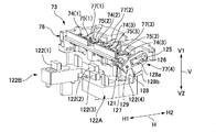
- FIG. 13 is a partial perspective view showing the wiper holder unit 73 of the wiper unit 70
- FIGS. 14A and 14B are a perspective view and a side view showing the wiper selection mechanism.
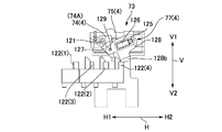
- 15A to 15C are explanatory views showing the wiper raising operation by the wiper raising member.
- 16A to 16C are explanatory views showing a wiper overturning operation by the wiper overturning member.
- the wiper holder unit 73 includes a slide frame 76 which can slide in the wiper movement direction H along the guide shafts 72 on both sides.
- a turning central axis 121 is bridged in a direction orthogonal to the wiper movement direction H.
- wiper holders 74 (1) to 74 (4) are attached to the turning center shaft 121 in the axial direction.
- Wipers 75 (1) to 75 (4) are attached to the wiper holders 74 (1) to 74 (4), respectively.
- the wiper holders 74 (1) to 74 (4) can be switched between the first state and the second state with the pivoting center axis 121 as the center. In this example, it is possible to turn from the state of the falling position 74A which is the first state shown in FIG. 15A to the state of the rising position 74B which is the second state shown in FIG. 15C.
- the wipers 75 (1) to 75 (4) are in the posture of falling in the direction along the wiper movement direction H, and the tip edge thereof faces the home position 73 A of the wiper holder unit 73.
- the wipers 75 (1) to 75 (4) are in the standing posture facing the capping direction V 1 along the cap movement direction V. In the standing posture, the wipers 75 (1) to 75 (4) protrude from the slide frame 76 in the capping direction V1.
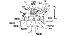
- Position holding arms 77 (1) to 77 (4) are attached to the wiper holders 74 (1) to 74 (4).
- the position holding arms 77 (1) to 77 (4) stably hold the wiper holders 74 (1) to 74 (4) in two positions, the falling position 74A and the rising position 74B.
- the position holding arms 77 (1), 77 (4) of the wiper holders 74 (1), 74 (4) on both sides are disposed outside of them and the inner wiper holder 74 2), 74 (3) position holding arms 77 (2), 77 (3) are arranged inside them.
- the structure of the position holding arms 77 (1) to 77 (4) will be described with reference to FIG. 15A. Since the position holding arms 77 (1) to 77 (4) have the same structure, the structure will be described by taking the position holding arm 77 (4) as an example.
- a support shaft 125 is bridged over the slide frame 76 in parallel with the turning center shaft 121.
- the support shaft 125 is disposed on the side of the home position 73 A of the wiper holder unit 73 with respect to the pivoting center shaft 121.
- the position holding arm 76 (4) includes a compression coil spring 126, a link 127, and a link 128.
- the link 127 is integrally formed or fixed to the wiper holder 74 (4), and pivots integrally with the wiper holder 74 (4) about the pivot center axis 121.
- the link 128 is supported by the support shaft 125 so as to be pivotable about the support shaft 125.
- the distal end of the link 127 and the distal end of the link 128 are rotatably coupled with each other by the coupling pin 129.
- the link 128 is formed with an elongated shaft hole 128 a into which the support shaft 125 is inserted.
- the compression coil spring 126 always presses the link 128 toward the connecting pin 129 with respect to the support shaft 125.
- FIGS. 15A to 15C in order to turn the wiper holder 74 (4) from the fall position 74A to the upright position 74B, the compression coil spring 126 needs to be compressed. Conversely, also when the wiper holder 74 (4) is returned from the standing position 74B to the falling position 74A, the compression coil spring 126 needs to be compressed. As shown in FIG.
- the compression coil spring 126 is compressed most when the connecting pin 129 is positioned on a straight line connecting the center axis of pivoting 121 and the center of the support shaft 125. Therefore, the position holding arm 76 (4) is pressed by the spring force of the compression coil spring 126 toward either the falling position 74A or the rising position 74B with this position as the boundary.
- the wiper holder 74 (4) is stably held at any of these positions. That is, the wipers 75 (1) to 75 (4) are reliably held at the standing position during wiping, and wiping can be performed reliably. In addition, the wipers 75 (1) to 75 (4) in the fallen position do not stand up unnecessarily.
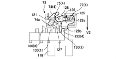
- a plurality of wiper raising members functioning as a wiper engaging member for switching the state of the wiper from the first state to the second state Is arranged.
- four wiper raising members 122 (1) to 122 (for use in raising each of the wiper holders 74 (1) to 74 (4) from the falling position 74A to the rising position 74B. 4) is arranged.
- the wiper raising members 122 (1) and 122 (2) vertically protrude from the top surface of the substrate 122A, and the wiper raising members 122 (3) and 122 (4) vertically protrude from the top surface of the substrate 122B.
- the substrates 122A and 122B are fixed to the upper surface of the cover 90A of the wiper pump drive transmission mechanism 90 having a predetermined height attached to the bottom plate 51 of the device frame 50.
- the wiper raising members 122 (1) to 122 (4) are disposed at different positions along the wiper movement direction H, as shown in FIGS. 10 and 14A. Further, in the width direction of the wiper unit 70 orthogonal to the wiper movement direction H, the wiper raising members 122 (1) to 122 (4) are the position holding arms 77 (1) of the wiper holders 74 (1) to 74 (4). ) To 77 (4). As shown in FIGS. 14A and 14B, the link 128 of each of the position holding arms 77 (1) to 77 (4) is formed with an engagement protrusion 128b projecting in the capping release direction V2.
- the wiper holder unit 73 is moved in the wiper movement direction H to the position where the wiper raising members 122 (1) to 122 (4) are disposed.
- the engagement protrusions 128b of the position holding arms 76 (1) to 76 (4) of the four wiper holders 74 (1) to 74 (4) are moved in the cap moving direction V by the corresponding wiper raising member 122.
- One of (1) to 122 (4) can be faced.
- the cap unit 60 is moved in the capping release direction V2.
- the wiper unit 70 is also moved in the capping release direction, and the engaging projection 128b hits one of the corresponding wiper raising members 122 (1) to 122 (4).
- FIG. 15A shows this state.
- the engagement protrusions 128b are relatively pushed up in the capping direction V1 by the wiper raising members 122 (1) to 122 (4).
- the position holding arms 77 (1) to 77 (4) are in a position where the wiper holders 74 (1) to 74 (4) are inclined against the spring force of the compression coil spring 126. Raise from 74 to the standing position 74B.
- the wiper holder unit 73 is moved in the wiper movement direction H and positioned at a position before the head units 21 to 24 and 31 to 34 to be wiped.
- the cap unit 60 is moved in the capping direction V1
- the wipers 75 (1) to 75 (4) that have stood up are the nozzle surfaces 21a to 24a and 31a to 34a of the head units 21 to 24 and 31 to 34. Set to a position where wiping is possible.
- the wiper holder unit 73 is moved along the wiper movement direction H, the corresponding head units 1-1 to 1-4, 2- can be moved by the wipers 75 (1) to 75 (4) mounted thereon. Wiping of the nozzle surfaces 1-1a to 1-4a and 2-1a to 2-4a of 1 to 2 is performed.
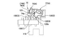
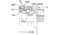
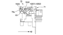
- the wiper is switched from the second state to the first state on the inner end face of the wiper holder unit 73 on the home position 73A side.
- a plurality of wiper lowering members that function as wiper engaging members are disposed.
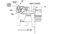
- two wiper overturning members 123 (1) and 123 (2) extending in the wiper movement direction H are provided.
- the wiper overturning member 123 (1) is a member for lowering the wiper holders 74 (1) and 74 (2) from the upright position 74A to the downturned position 74B
- the wiper overturning member 123 (2) is the wiper holder 74 (3), 74.
- (4) is a member for falling from the standing position 74A to the falling position 74B.
- the wiper holders 74 (1) to 74 (4) are respectively formed with engagement protrusions 74a extending in the capping release direction.
- the engagement protrusions 74a of the wiper holders 74 (1) and 74 (2) are formed at adjacent positions.
- the engaging projections 74a move toward the home position 73A of the wiper holder unit 73 along the wiper movement direction H, they can simultaneously contact one wiper overturning member 123 (1).
- the respective engaging protrusions 74a of the wiper holders 74 (3) and 74 (4) are formed at adjacent positions, and can be simultaneously brought into contact with one wiper tilting member 123 (2).
- the wiper selection operation in other words, the selection operation of the head unit to be wiped
- one of the plurality of wipers 75 (1) to 75 (4) can be selected.
- the head units 21 to 24 and 31 to 34 can be selectively wiped.
- Three restriction members 130 (1) to 130 (3) are formed on the substrates 122A and 122B on which the wiper raising members 122 (1) to 122 (4) are formed.
- the restricting member 130 (1) prevents the wiper holder 74 (1) from pivoting to the upright position with the wiper holder 74 (2), and the restricting member 130 (3) causes the wiper holder 74 (3) to It prevents pivoting to the upright position with the holder 74 (4). Further, the restricting member 130 (4) prevents the wiper holder 74 (4) from pivoting to the upright position together with the wiper holder 74 (3).
- a restriction member for preventing the wiper holder 73 (1) from pivoting to the upright position together with the wiper holder 74 (2) is not shown.
- restricting members 130 (1) to 130 (3) protrude perpendicularly to the capping direction V 1 from the upper surfaces of the substrates 122 A and 122 B, and an engaging end face 130 a extending in the cap moving direction V is formed.
- the link 127 in each of the wiper holders 74 (1) to 74 (4) is formed with an engaging end face 127a extending in the cap moving direction V in the state of the falling position 74A.
- the engagement end face 127a of the link 127 of the wiper holder 74 (4) is a wiper relative to the engagement end face 130a of the regulating member 130 (2). Face each other with a slight gap from the moving direction H.
- the engagement end face 127a abuts on the engagement end face 130a of the regulating member 130 (2).
- the wiper holder 74 (3) does not pivot together with the wiper holder 74 (4) toward the standing position 74B.
- the wiper holders 74 (3) and 74 (4) stick to each other.
- the other wiper holder 74 (3) may be erected along with it.
- the restriction member 130 (2) can reliably prevent the non-selected wiper holder from rising.
- both end portions of the tip end portion of the wiper pressed against the nozzle surface are likely to be largely deformed.
- foreign matter such as ink can not be reliably wiped off from the portion of the nozzle surface that is in contact with both sides of the wiper tip edge.
- the flat wiper is bent in an arc to increase the rigidity, foreign substances such as ink adhering to the nozzle surface can be wiped off reliably on both sides of the front end of the wiper.
- the maintenance device 40 of this example is provided with a wiper and a wiper cleaner unit having the configuration described below.
- FIG. 17 is an explanatory view showing an end portion of the wiper unit 70 on the home position side.
- the wiper holder unit 73 When the wiper holder unit 73 is at the home position 73A, the four wipers 75 (1) to 75 (4) are tumbled by the wiper folding members 123 (1) and 123 (2) to be in the collapsed position. ing.
- the wiper 75 (4) is shown in the upright position and the wiper 75 (2) is shown in the middle of turning from the fallen position to the upright position in order to clearly show the wiper shape. It is
- the wiper 75 (1) is attached to the wiper holder 74 (1) in a state in which a flat rubber having a rectangular contour is bent in an arc shape.
- the wiper 75 (1) has a convex curved surface 75a, the wiping surface 75a facing in the wiping direction H2. Therefore, the tip edge 75b of the wiper 75 (1) sliding on the nozzle surfaces 1-1a and 1-3a of the head units 1-1 and 1-3 to be wiped is similarly bent in the wiping direction H2. It has the same shape.
- the wiper 75 (1) shaped into a circular arc so that the wiping direction H 2 is a convex curved surface has higher rigidity at the time of wiping than a flat wiper.
- both end sides of the tip edge portion are deformed significantly, and the nozzle surfaces 1-1a and 1-3a
- the curved tip edge 75b of the wiper 75 (1) slides along the nozzle surfaces 1-1a and 1-3a in a state where the respective portions uniformly abut on the nozzle surfaces 1-1a and 1-3a. Move. Therefore, appropriate wiping can be performed compared to a flat wiper.
- the other wipers 75 (2) to 75 (4) also have the same shape as the wiper 75 (1), so the description thereof is omitted.
- a wiper cleaner unit 150 is attached to the wiper unit 70.
- the wiper cleaner unit 150 includes a plate-like wiper cleaner 151.
- the wiper cleaner 151 is bridged in the direction of the short side of the wiper frame 71 on the upper surface of the wiper frame 71.
- the arrangement position of the wiper cleaner 151 is a position between the wiper holder unit 73 located at the home position 73A and the cap unit 60.
- cleaner support plates 152 and 153 extending in a direction H1 (forward direction of the wiper) opposite to the wiping direction H2 are integrally formed.
- the tip end portions of the cleaner support plates 152 and 153 are movable in the direction toward and away from the upper surface of the wiper frame 71 centering on the support shaft 154 (only one support shaft 154 is shown in the figure). , And is attached to the wiper frame 71.
- the cleaner support plates 152 and 153 are always pressed in the direction of being lifted from the upper surface of the wiper frame 71 by the rod-like spring member 155 supported on the wiper frame 71 side.
- the wiper cleaner 151 is in a state of being floated up at substantially the same height position as the contact surface 71 a of the wiper frame 71.
- concave end surfaces 151 (1) to 151 (4) (wiper cleaning surface) for wiper cleaning are formed at four positions.
- the concave end surfaces 151 (1) to 151 (4) have a shape corresponding to the curved shape of the tip end edge 75b of the wipers 75 (1) to 75 (4). Further, the concave end surfaces 151 (1) to 151 (4) are located on the movement locus of the leading edge 75b of the wipers 75 (1) to 75 (4) in the standing position.
- the wipers 75 (1) to 75 (4) wipe the nozzle surfaces 1-1a to 1-4a and 2-1a to 2-4a of the head units 1-1 to 1-4 and 2-1 to 2-4. After completion, the home position 73A is returned from the wiping end position. At this time, the wipers 75 (1) to 75 (4) pass the wiper cleaner 151. When passing the wiper cleaner 151, the leading edge 75b of each wiper 75 (1) to 75 (4) slides on each concave end surface 151 (1) to 151 (4). As a result, the ink etc. adhering to the leading edge 75 b of the wipers 75 (1) to 75 (4) are wiped off by the concave end faces 151 (1) to 151 (4).
- the wiper cleaner unit 150 includes a pair of ink recovery units 156 and 157 that recover the ink and the like wiped off by the wiper cleaner 151. As described with reference to FIG. 6, the ink recovery portions 156 and 157 are attached to one end of the first and second cap bases 62 and 63 in the cap unit 60.
- the ink recovery units 156 and 157 include plate-like ink absorbing materials 156 a and 157 a and mounting units 156 b and 157 b on which these are mounted.
- the abutment surfaces 71a on both sides of the wiper unit 70 abut the lower surface portion 10a (see FIG. 4) of the head carriage 10 surrounding the nozzle surface 11a of the inkjet head 11.
- the wiper cleaner 151 is disposed at a position adjacent to the head carriage 10, and the wiper cleaner 151 also hits the lower surface portion 10 a of the head carriage 10. As a result, the wiper cleaner 151 is pushed into the wiper frame 71 side.
- the portions including the concave end surfaces 151 (1) to 151 (4) are in a state of being pressed against the ink absorbents 156a and 157a of the ink recovery portions 156 and 157.
- foreign substances such as ink adhering to the concave end faces 151 (1) to 151 (4) of the wiper cleaner 151 are absorbed by the ink absorbing materials 156a and 157a and recovered.
- the wiper cleaner 151 When the cap unit 60 is returned from the capping state to the standby position, the wiper cleaner 151 is separated from the lower surface portion 10 a of the head carriage 10. As a result, it returns to the state of being lifted up from the upper surface of the wiper frame 71 again. That is, the wiper cleaning position where the concave end surfaces 151 (1) to 151 (4) can come in contact with the leading edge 75a of the wipers 75 (1) to 75 (4) moving in the standing position returns to the wiper cleaning position.
- the ink film surface may be formed between the nozzle surface and the lip due to the residual adhesion ink or the like of the lip (opening edge) of the cap.
- the cap in contact with the nozzle face in parallel with the nozzle face is peeled off from the nozzle face in parallel to the nozzle face, the ink film surface formed between the nozzle face and the lip is ruptured.
- the ink film surface is ruptured, the ink forming the ink film surface may be scattered to the side of the nozzle surface and adhere to the nozzle surface. If ink adheres to the nozzle surface, there is a possibility that ink droplets can not be properly ejected from the ink nozzle.
- the cap capped parallel to the nozzle surface may be peeled off from the nozzle surface while being inclined to the nozzle surface such that one end of the cap is first separated from the nozzle surface.
- the operation of peeling off while inclining the cap with respect to the nozzle surface is referred to as “diagonal peeling off of the cap”, and the mechanism is referred to as “cap oblique peeling off mechanism”.
- the cap is oblique to the nozzle surface means that the lip surface of the cap in contact with the nozzle surface is inclined to the nozzle surface. It is desirable from the viewpoint of miniaturizing and compactizing the maintenance device to realize such an oblique peeling mechanism of the cap with a small number of parts and a simple configuration.
- a large number of head units are arranged in the nozzle row direction.
- a number of caps corresponding to the head unit may be used.
- a cap diagonal peeling mechanism 160 is attached to the cap unit 60 of this example.
- the cap diagonal peeling mechanism 160 is provided for each of the caps 64 (1) to 64 (4) and 65 (1) to 65 (4) with the nozzle surface 1 of the head units 1-1 to 1-4 and 2-1 to 2-4
- the lip surface end face of the cap opening edge
- the lip surface is gradually inclined with respect to the nozzle surface 11a.
- FIGS. 18A to 21 are explanatory views schematically showing the configuration and the operation of the cap oblique peeling mechanism 160.
- FIG. 19 is a perspective view showing the cap unit 60 and the side plates 52 and 53 on both sides of the device frame 50, with the caps 64 (1) to 64 (4) removed.
- FIG. 20 is a perspective view showing the cap unit 60 and the cap 64 (2), and the cap base 63 and the caps 64 (1), 64 (3), 64 (4), 65 (1) to 65 (4) are removed. Show the condition.
- FIG. 21 is a perspective view showing the slide mechanism of the moving member used to realize the oblique peeling operation of the cap incorporated in the cap unit 60. As shown in FIG.
- each of the caps 64 (1) to 64 (4) and 65 (1) to 65 (4) are the same for oblique peeling of the caps, they are mounted on the cap base 63
- the cap 65 (3) will be described as an example.
- the cap 65 (3) comprises an elongated rectangular parallelepiped cap main body 64a, and a lip 64b having a rectangular or oval outline opened on the upper surface of the cap main body 64a. ing. Positioning protrusions 64c protruding upward are formed at both end portions in the long side direction on the upper surface of the cap main body portion 64a. The lip portion 64b located between the protrusions 64c protrudes upward from the upper surface of the cap main portion 64a.
- the cap body 64a is made of, for example, a hard plastic material.
- the lip portion 64b is formed of a soft plastic material or a rubber material.
- the cap base 63 has an elongated rectangular parallelepiped shape as a whole, and four caps 65 (1) to 65 (4) are attached to the top plate portion 161. Two rectangular openings 162 (1) to 162 (4) (hereinafter collectively referred to as openings 162) are formed.
- the cap 65 (3) attached to the opening 162 is supported by a pair of compression coil springs 63a.
- the pair of compression coil springs 63a are disposed between the cap main body 64a of the cap 65 (3) and the bottom plate portion 163 of the cap base 62, as shown in FIG.
- the pair of compression coil springs 63a support both end portions in the long side direction of the cap main body portion 64a, and press the cap 65 (3) against the cap base 63 in the capping direction V1 (upward in the drawing) There is.
- a pair of cap-side engaging protrusions 164 and 165 are formed on each of the side surface portion 64d and the opposite side surface portion 64e of the cap body portion 64a (side surfaces The engaging projection on the side of the portion 64d is not shown).
- the engagement protrusions 164 and 165 vertically protrude from the side surface portions 64d and 64e, and are located at portions on both end sides in the long side direction of the cap body portion 64a.
- the upper surfaces of the cap-side engagement protrusions 164 and 165 are cap-side engagement surfaces 164 a and 165 a parallel to the lip surface 64 f of the lip portion 64 b.
- the cap side engagement surfaces 164a and 165a are located on the same plane.
- the back surfaces of the base side engaging portions 166 and 167 are base side engaging surfaces 166 a and 167 a located on the same plane.
- the cap 65 (3) is pressed in the capping direction by the compression coil spring 63a.
- the cap side engaging surfaces 164a and 165a of the cap 65 (3) are pressed against the base side engaging surfaces 166a and 167a from the side of the capping release direction V2 (from the lower side in the drawing).
- the cap 65 (3) is held in a posture parallel to the nozzle surface 2-3a. That is, the lip surface 64f is held parallel to the nozzle surface 2-3a.
- a base side engaging surface 166b is formed which is retracted by a predetermined step in the capping direction V1.
- the base side engagement surface 166b is formed at a position adjacent to the base side engagement surface 167a in the base side engagement surface 166a.
- a movable member 168 of a fixed thickness is mounted so as to be slidable in the long side direction.
- the thickness of the moving member 168 is set to be larger than the difference in level between the base side engagement surface 166a and the base side engagement surface 166b.
- the moving member 168 is slidable between an advanced position 168A shown in FIGS. 18A and 18C and a retracted position 168B shown in FIG. 18B.
- the moving member 168 In the advanced position 168A, the moving member 168 is located between the base engagement surface 167b and the cap engagement surface 164a.
- the moving member 168 In the retracted position 168B, the moving member 168 is located at the retracted position out of the space between them.
- the cap 65 (3) is maintained in a posture parallel to the nozzle surface 2-3a. Be done.
- the cap side engagement surface 164a sandwiches the moving member 168 and is pressed against the base side engagement surface 166b, as shown in FIG. 18C, the cap 65 (3) Then, it is inclined obliquely by the thickness of the moving member 168.
- one end of the cap 65 (3) in the long side direction has the cap side engaging surface 164a sandwiching the moving member 168 and is pressed against the base side engaging surface 166b, and the cap 65 (3) in the long side direction
- the cap-side engagement surface 165a is pressed against the base-side engagement surface 167a, so that the cap 65 (3) moves relative to the nozzle surface 2-3a along its long side direction. Will be inclined by the thickness of the
- a slide mechanism for sliding the moving member 168 to the advanced position 168A and the retracted position 168B will be described.
- the slide mechanism converts the movement of the cap unit 60 in the capping direction V1 by the cap drive transmission mechanism 90 into a movement of the moving member 168 from the retracted position 168B to the advanced position 168A. Further, the movement of the cap unit 60 in the capping release direction V2 is converted to the movement of the moving member 168 from the advanced position 168A to the retracted position 168B.
- the moving member 168 By using the movement of the cap unit 60 by the cap drive transmission mechanism 80 to move the moving member 168, a unique driving source for moving the moving member 168 is not necessary. Further, the moving member 168 can be appropriately moved in accordance with the movement position of the cap 65 (3), and the movement control can also be performed easily and accurately.
- the slide mechanism 170 includes a pair of pivotable levers 171 and 172 disposed on the cap unit 60.
- the levers 171 and 172 are attached to both ends of the support shaft 173, and can pivot around the support shaft 173.
- the support shaft 173 is supported by the cap frame 61 and is bridged in the short side direction.
- the side plate portions 52, 53 of the device frame 50 have a pair of first engagement pieces 174, 175 engageable with the respective levers 171, 172 and a pair of second engagement pieces 176, 177. Is formed.
- the first engagement pieces 174, 175 engage the levers 171, 72 moving in the capping direction V1 to pivot the levers to the first position shown in FIGS. 18A, 18B.
- the levers 171 and 172 hit the first engagement pieces 174 and 175 and pivot to the first position immediately before the cap 64 is in the capping state.
- the second engagement pieces 176, 177 engage with the levers 171, 172 moving in the capping release direction V2 to turn the lever from the first position to the second position shown in FIG. 18C.
- the cap 65 moves in the capping release direction, and the levers 171 and 172 hit the second engagement pieces 176 and 177 and pivot to the second position just before reaching the retracted position.
- the levers 171 and 172 are connected to the slide units 181 and 182 via the connecting portion 178.
- the slide unit 181 is supported by the cap base 62 so as to be slidable in the direction of its long side.
- the slide unit 182 is supported by the cap base 63 so as to be slidable in the direction of its long side.
- Moving members 168 are formed in the slide unit 181 at four locations. The moving members 168 are located at portions corresponding to the base side engaging surfaces 166 b of the caps 64 (1) to 64 (4), respectively. Similarly, moving members 168 are formed in the slide unit 182 at four locations. The moving members 168 are located at portions corresponding to the cap side engaging surfaces 166b of the caps 65 (1) to 65 (4), respectively.
- the connecting portion 178 converts the pivotal movement of the levers 171 and 172 into the sliding movement of the slide units 181 and 182 between the levers 171 and 712 and the slide units 181 and 182. That is, as shown in FIG. 18A, the connecting portion 178 includes slide grooves 171a and 172a formed in the levers 171 and 172, and a connecting shaft 179 which is spanned by the slide units 181 and 182. The connecting shaft 179 extends through the slide grooves 171a and 172a in a slidable manner along the slide grooves 171a and 172a.
- FIGS. 22A to 22E are explanatory views showing the operation of the oblique peeling mechanism accompanying the movement of the cap 64.
- FIG. The operation of the oblique peeling mechanism will be summarized below with reference mainly to these figures.
- the cap 65 (3) receives the spring force of the compression coil spring 63a by the nozzle surface 2-3a. Oppositely, it is pushed into the side of the cap base 63. Thus, a gap is formed between the cap side engagement surface 164a and the base side engagement surface 166b so that the moving member 168 can be advanced. Therefore, at or just before the capping state is formed, the moving member 168 is advanced to position the moving member 168 between the cap side engagement surface 164a and the base side engagement surface 166b.
- the cap drive transmission mechanism 80 moves the cap unit 60 in the capping release direction V2 with the moving member 168 advanced, the cap 65 (3) can be peeled off from the nozzle surface 2-3a.
- the cap 65 (3) is released from being pushed by the nozzle surface 2-3a, and is pushed relative to the cap base 63 in the capping direction V1.
- the cap side engagement surface 164a sandwiches the moving member 168 at the advanced position 168A and is pressed to the side of the base side engagement surface 166b.
- the cap 65 (3) is inclined with respect to the nozzle surface 2-3a. That is, the lip surface 64d of the cap 65 (3) is peeled from the nozzle surface 2-3a from one end in the long side direction to the other end.
- the cap 65 (3) is inclined with respect to the nozzle surface 2-3a by the thickness of the moving member 168.
- the cap 65 (3) moves in the capping release direction V2 and remains in an oblique posture with respect to the nozzle surface 2-3a, It leaves from the nozzle face 2-3a.
- the moving member 168 moves to the retracted position 168B. That is, the moving member 168 is returned to the retracted position 168B immediately before the cap unit 60 moves in the capping release direction V2 and reaches the standby position.
- the cap side engagement surface 164a returns to the state where it is directly pressed against the base side engagement surface 166a. Thereby, the cap 65 (3) returns to the posture parallel to the nozzle surface 2-3a.
- the cap side engagement surfaces 164a and 165a of the cap 65 (3) are pressed against the base side engagement surfaces 166a and 167a. Therefore, as shown in FIG. 22D (FIG. 18C), the cap 65 (3) is in a posture parallel to the nozzle surface 2-3a.
- the cap drive transmission mechanism 80 moves the cap unit 60 in the capping direction V1
- the cap 65 (3) contacts the nozzle surface 2-3a in a posture parallel to the nozzle surface 2-3a.
- the cap 65 (3) supported by the compression coil spring 63a is relatively pushed in the capping removal direction V2 by the nozzle surface 2-3a.
- the moving member 168 is interposed between the cap-side engagement surface 164a and the base-side engagement surface 166b. There is a gap that can be advanced. Then, the capping state shown in FIG. 22A described first is formed.
- the cap 65 (3) can be peeled off obliquely from the nozzle surface 2-3a.
- the capping state when the ink film surface is formed between the nozzle surface 2-3a and the lip surface 64d of the cap 65 (3), the ink film surface is ruptured by peeling off the cap 65 (3) obliquely Can be prevented. Accordingly, it is possible to prevent the ink adhesion to the nozzle surface 2-3a due to the rupture of the ink film surface.
- the cap 65 (3) can be returned to a posture parallel to the nozzle surface 2-3 a by retracting the moving member 168 after peeling the cap 65 (3) from the nozzle surface 2-3 a.
- a detection mechanism is provided that detects the discharge state of ink droplets from each nozzle of the head unit 22 using the change in capacitance between the in-cap electrode and the electrode on the nozzle surface side. There is. In this case, if the nozzle surface 2-3a and the cap 65 (3) are not parallel to each other, the state of each nozzle may not be accurately detected. According to this embodiment, such adverse effects can be avoided.
- the cap 65 (3) is displaced relative to the nozzle surface 2-3a, and the nozzle surface 2-3a can be reliably made. There is a possibility that it can not be capped.
- the cap 65 (3) may be in a half-contact state, and a close contact state between the lip surface 64d of the cap 65 (3) and the nozzle surface 2-3a may not be formed. Such adverse effects can also be resolved.
- the plurality of moving members 168 can be moved simultaneously. Further, since the mechanism for sliding the slide units 181 and 182 is performed by using the movement of the cap drive transmission mechanism 80, there is no need to separately arrange a drive source. Thus, the mechanism for obliquely removing the plurality of caps for capping the plurality of head units can be made compact and simple.
- FIG. 23 is a schematic block diagram showing a control system of the printer 1.
- the control system of the printer 1 is provided with a control unit 210 mainly configured of a computer.
- a print command including print data is supplied to the control unit 210 from, for example, the host computer 220 on the upper side via the input / output unit 211.
- the control unit 210 transports the recording sheet P by controlling the driving of the recording sheet transport mechanism 212 including the sheet feeding motor 12 and the feeding motor 6 and the like.
- drive control of the carriage drive mechanism 213 is performed to move the carriage 10.
- drive control of the head driver 214 is performed to cause the inkjet head 11 to perform a printing operation.
- the control unit 210 drives and controls the carriage drive mechanism 213 to return the carriage 10 to the home position B when the power is off or in the printing standby state. At the home position B, drive control of each part of the maintenance device 40 is performed to execute a predetermined maintenance operation on the inkjet head 11.
- the control unit 210 drives and controls the cap drive transmission mechanism 80 to perform the capping operation.
- the movement position of the caps 64 and 65 is controlled based on the cap standby position (origin) detected by the position detector 86 and the output of the rotary encoder 215 attached to the motor 83. Further, the wiper-pump drive transmission mechanism 90 is drive-controlled to execute the wiping operation of the nozzle surface 11 a.
- the movement position of the wiper 75 is controlled based on the home position 73 A (origin) of the wiper holder unit 73 detected by the position detector 216 and the output of the rotary encoder 217 attached to the motor 91.
- the position detector 216 is assembled between the wiper frame 71 and the wiper holder unit 73.
- the position detector 216 can be constituted by a photocoupler attached to the wiper frame 71 and a detection piece for light shielding attached to the wiper holder unit 73.
- the operation state of the printer 1 is displayed on the operation / display unit 218.
- FIGS. 24 to 27C collectively show the movement positions of the respective parts of the maintenance device 40 of the printer 1.
- head 1 means head units 1-1 to 1-4
- head 2 means head units 2-1 to 2-4.
- FIG. 24 is a list showing cap positions.
- the cap position numbers 1 to 12 are positions in the cap movement direction V of the cap unit 60.
- the “cap home detection position” of the cap position number 9 is a normal standby position of the cap unit 60.
- the cap unit 60 is located at the standby position when the power is off, during printing standby, and during printing. This position is a position detected by the position detector 86.
- valve selection position (head 2) (number 10) and valve selection in which the cap unit 60 is moved in the capping release direction V2 than the “cap home detection position” (standby position) Move to the position (head 1) "(number 12).
- “Valve selection position (head 1)” is the position of the cap unit 60 when selecting the valves 112A to 115A for sucking the head units 1-1 to 1-4 (caps 64 (1) to 64 (4)) is there.
- “Valve selection position (head 2)” is a position moved further in the capping release direction V2 and a valve for sucking the head units 2-1 to 2-4 (caps 65 (1) to 65 (4)) This is the position of the cap unit 60 when selecting 112B to 115B.
- the “wiper raising position” (number 11) between them is the position of the cap head 60 when raising the wiper 75 so that the nozzle surfaces 1-1a to 1-4a and 2-1a to 2-4a can be wiped. is there.
- FIGS. 25A and 25C are explanatory views showing the position (wiper position) of the wiper holder unit 73 at the time of valve selection.
- the position numbers 1 to 6 indicate the position of the wiper movement direction H of the valve selector 117A when the valves 112A to 115A (head units 1-1 to 1-4) are selectively suctioned. .
- These positions are managed by the movement distance of the wiper holder unit 73 from the home position 73A (wiper home detection position).
- position numbers 7 to 11 indicate the position of the wiper movement direction H of the valve selector 117B when the valves 112B to 115B (head units 2-1 to 2-4) are selectively suctioned. .
- Position numbers 7 to 11 are the same positions as wiper position numbers 1 to 6, respectively.
- FIGS. 26A and 26B are explanatory diagrams showing the position of the wiper holder unit 73 when the wiper is selected.
- the position indicated by the position number 13 is a position where the wiper 75 (1) for wiping the head units 1-1, 1-3 by the wiper raising member 122 (1) is raised.
- the position indicated by the registration number 14 is a position for raising the wiper 75 (2) which wipes the head units 1-2, 1-4 by the wiper raising member 122 (2).
- the position number 15 is a position where the wiper 75 (3) for wiping the head units 2-1, 2-3 by the wiper raising member 122 (3) is erected.
- the position number 16 is a position for raising the wiper 75 (4) which wipes the head units 2-2, 2-4 by the wiper raising member 122 (4).
- FIG. 27A, FIG. 27B and FIG. 27C are explanatory drawings showing the position of the wiper holder unit 73 at the start of wiping.
- the position number 18 is a wiping start position of the head unit 1-1 and the head unit 2-1 by the wiper 75 (1) and the wiper 75 (3).
- the position number 19 is a wiping start position of the head units 1-2 and 2-2 by the wipers 75 (2) and 75 (4).
- the position number 20 is a wiping start position of the head units 1-3 and 2-3 by the wipers 75 (1) and 75 (3).
- the position number 21 is a wiping start position of the head units 1-4 and 2-4 by the wipers 75 (2) and 75 (4).
- the position number 22 is a standby position of the wiper 75 at the time of ink suction.
- the position 23 is a movement position of the wiper holder unit 73 at the time of selective initialization of ink suction.
- the position number 24 is a position where the wiper cleaner 151 cleans the wiper 75.
- the ink jet head 11 stands by at the home position B when the printer 1 is turned off and in the printing standby state.
- the position of the cap unit 60 is the "capping position" (FIG. 24) closest to the nozzle surface 11a.
- the caps 64 (1) to 64 (4) and the caps 65 (1) to 65 (4) mounted on the cap unit 60 are the nozzle surfaces 1-1a to 1 of the corresponding head units 1-1 to 1-4. -4a and in the capping state in which the nozzle surfaces 2-1a to 2-4a of the head units 2-1 to 2-4 are capped.
- horizontal cam surfaces 82c and 82d parallel to the nozzle surfaces 20a and 30a are formed continuously with the tip of the cam surfaces 82a and 82b of the spiral cams 81a and 81b of the cap drive transmission mechanism 80 (FIG. 7A Etc.).
- the roller (cam follower) 66 on the cap unit 60 side is in a state of riding on the horizontal cam surfaces 82 c and 82 d. Thereby, the cap unit 60 is held in the stable state at the “capping position”.
- vibration is applied to the maintenance device 40, the cap unit 60 does not move away from the nozzle surface 11a.
- the wiper unit 70 is located at a contact position in contact with the carriage 10. At this contact position, the contact surface 71a of the wiper frame 71 is in pressure contact with the lower surface portion 10a of the carriage 10 of the ink jet head 11 by the spring force of the tension coil spring 108b.
- the wiper holder unit 73 stands by at the home position 73A (FIG. 25A to 25C: wiper home detection position) at one end of the wiper unit 70 in the long side direction.
- the wiper 75 mounted on the wiper holder unit 73 is in the state of falling down.
- the wiper cleaner 151 mounted on the wiper unit 70 is pressed against the wiper frame 71 by the lower surface portion 10 a of the carriage 10. Therefore, the wiper cleaner 151 is pressed against the ink absorbents 156 a and 156 b of the ink recovery units 156 and 157. Foreign matter such as ink adhering to the wiper cleaner 151 is absorbed to the side of the ink absorbents 156a and 156b.
- the wiper and pump drive transmission mechanism 90 is switched to a state in which the ink suction pump 94 can be driven (a state in which ink suction is possible).
- valves 112A to 115A and 112B to 115B disposed between the caps 64 (1) to 64 (4) and 65 (1) to 65 (4) and the ink recovery portion of the ink cartridge 14 are for nozzle meniscus protection.
- the valve fully open levers 119A, 119B are in a state of being pushed in by the valve selectors 117A, 117B (FIGS. 25A to 25C: valve fully open position).
- the nozzles are open to the atmosphere via the valves 112A to 115A and 112B to 115B.
- the moving member 168 has advanced to the advancing position 168A.
- the motor 83 is driven to rotate the spiral cams 81a and 81b.
- the cap unit 60 moves in the capping release direction V2 (retraction direction) along the cap movement direction V.
- the caps 64 (1) to 64 (4) and 65 (1) to 65 (4) are pressed against the nozzle surfaces 1-1a to 1-4a and 2-1a to 2-4a with a predetermined pressing amount.
- the lip surface 64f of the caps 64 (1) to 65 (1) to 65 (4) is controlled by the spring force of the spring members 62a and 63a.
- the nozzle surfaces 1-1a to 1-4a and 2-1a to 2-4a are pressed.
- the moving member 168 is at the advanced position 168A.
- one cap-side engaging surface 164 a sandwiches the moving member 168 and the base of the cap bases 62 and 63. It faces the side engagement surface 166b.
- the other cap-side engagement surface 165a faces the base-side engagement surface 167a.
- the cap unit 60 (cap bases 62 and 63) moves in the capping release direction V2, and one of the base side engaging surfaces 166b abuts on the moving member 168 to press the moving member 168 against the cap side engaging surface 164a.
- the cap 64 (1) to 64 (4) and 65 (1) to 65 (4) are pushed in the capping release direction V2 from the corner on the side of the moving member 168. . Therefore, as the cap unit 60 moves, the caps 64 (1) to 64 (4) and 65 (1) to 65 (4) are moved to the nozzle surfaces 1-1a to 1-4a and 2-1a to 2-4a. Gradually tilt from a parallel posture. As a result, the lip surface 64f of each cap first leaves the corner on the side of the moving member 168 from each nozzle surface. The portion of the lip surface 64 f away from the nozzle surface gradually moves toward the other end of the lip surface 64 f.
- cap unit 60 (cap base 62, 63) is further moved in the capping release direction V2
- the other base side engaging surface 167a of the cap base 62, 63 directly contacts the cap side engaging surface 165a (FIG. 18B, FIG. 22B)).
- the lip surface 64f of each cap is separated from the nozzle surface as a whole, and the oblique peeling operation of the cap is completed.
- the position of the cap unit 60 at this time is a position between the "flushing position" and the "pump suction position" in FIG.
- each cap moves in the capping release direction V2 together with the cap unit 60 while maintaining an oblique posture.
- the drive switching mechanism 100 switches the drive state of the wiper and pump drive unit 90.
- the cap unit 60 reaches the "pump suction position" (FIG. 24)
- the latch lever 102a of the first latch mechanism 102 is disengaged from the cam surface 106 on the device frame 50 side.
- the internal gear 93b of the planetary gear reducer 93 is latched by the first latch mechanism 102 so as not to rotate (see FIG. 8F).
- the latch lever 104a of the second latch mechanism 104 is pushed by the cam surface 105 on the device frame 50 side.
- the second latch mechanism 104 unlatches the planet carrier 93 c and allows the planet carrier 93 c to rotate.
- the wiper pump drive transmission mechanism 90 switches the wiper 75 to a movable state. In the unstable state during the drive state switching operation, the drive motor 91 is not driven.
- the wiper unit 70 is supported in a floating state by the device frame 50 via the tension coil spring 108 b. It does not follow the movement of the cap unit 60 and remains at the same position in the cap movement direction H. That is, the contact surface 71a of the wiper frame 71 is pressed against the lower surface portion 10a of the carriage 10 by the spring force of the tension coil spring 108b, and is held at the position in this state.
- the cap unit 60 further moves in the capping removal direction to reach the “wiping position” (FIG. 24).
- the lip surface 64 f of each cap reaches the position where it has moved in the capping release direction V 2 more than the wiper holder unit 73.
- the wiper holder unit 73 can be moved in the wiper movement direction V through the top of the cap unit 60 (the capping direction V1 side).
- the cap unit 60 moves in the capping release direction V2.
- the engaging projection 61 a of the cap frame 61 abuts on the rectangular frame portion 71 c of the wiper frame 71.
- the cap unit 60 and the wiper unit 70 move from the wiper unit abutting position 70A in the capping release direction V2.
- the contact surface 71 a of the wiper frame 71 of the wiper unit 70 gradually separates from the lower surface portion 10 a of the carriage 10.
- the carriage 10 can be moved.
- the wiper cleaner 151 mounted on the wiper unit 70 is released from the pressing by the lower surface portion 10 a of the carriage 10, and returns to the position lifted from the wiper frame 71.
- the wiper unit 70 moves to the standby position "cap home detection position" (FIG. 24) and stands by at this position.
- the maintenance device 40 in the capping state is in the standby state.
- the carriage 10 is moved to position the inkjet head 11 at the printing position B, and printing becomes possible.
- the cap unit 60 located at the standby position moves in the capping direction V1 to reach the “rushing position” (FIG. 24) and stops at this position.
- the lip surface 64f of each cap is not in contact with each nozzle surface but in a position close to the nozzle surface.
- the cap unit 60 in the standby position reaches the “defective nozzle inspection position” (FIG. 24) and stops at this position. This position is a position slightly moved in the capping direction V1 than the “flushing position”.
- each cap In the cap unit 60 in the standby position, each cap is held in parallel with each nozzle surface.
- the caps move to the "flushing position" and the "defective nozzle inspection position" while being in parallel.
- a defective nozzle inspection mechanism there has been known one which determines the discharge condition of the ink droplet based on the change in capacitance between the electrodes disposed on the head side and the cap side. In such a case, detection accuracy is ensured by maintaining both electrodes in parallel.
- each cap when moving from the standby position to the capping direction, each cap is held in a posture parallel to each nozzle surface, and a defective nozzle inspection is performed in this state. Therefore, when the defective nozzle is determined based on the change in capacitance, the inspection can be performed with high accuracy.
- valve selectors 117A and 117B on both sides are in the "valve fully open position" (FIGS. 25A to 25C).
- the cap unit 60 moves from the “defective nozzle inspection position” or the “flushing position” (FIG. 24) in the capping release direction V2 to the standby position “cap home detection position” (FIG. 24). Stop.
- the wiper holder unit 73 moves from the "wiper home detection position" (FIGS. 25A to 25C) which is the home position 73A in the wiper advancing direction H1 and stops at the "valve fully open position".
- the selector hooks 118A and 118B mounted on the wiper holder unit 73 are positioned at the valve selectors 117A and 117B in the wiper movement direction H, respectively.
- cap unit 60 stops at the position where it has moved the most in the capping release direction V2, "valve selection position (head 1)" (FIG. 24).
- the wiper unit 70 is also moved together with the cap unit 60, and the selector hooks 118A and 118B are engaged with the valve selectors 117A and 117B, respectively (ST1 in FIG. 12F).
- valve 2-1 position (“valve 2-1 position”) (FIGS. 25A to 25C).
- the valve selectors 117A and 117B engaged with the selector hooks 118A and 118B are also moved together and positioned at the "valve 1-1 position" (the "valve 2-1 position”).
- the valves 112A and 112B are opened, and ink suction from the caps 64 (1) and 65 (1) for capping the head units 1-1 and 2-1 becomes possible.
- the cap unit 60 moves in the capping direction V1 and stops at the "valve selection position (head 2)" (FIG. 24).
- the wiper unit 70 moves in the same direction together with the cap unit 60, and the selector hook 118A is disengaged from the valve selector 117A.
- the other selector hook 118B is maintained in engagement with the valve selector 117B (ST2 in FIG. 12F).
- valve 112A is switched to the open state, and the valve 112A is in the selected state. That is, only the valve 112A corresponding to the head unit 1-1 as the ink suction target can be opened.
- cap unit 60 moves in the capping direction V1 and stops at the standby position (FIG. 24: cap home detection position).
- the wiper holder unit 73 moves in the wiper advancing direction H1, stops at the “suction standby position” (FIGS. 27A to 27C), and stands by at this position.
- the cap unit 60 moves in the capping direction V1 and stops at the “capping position” (FIG. 24).
- the wiper and pump drive transmission mechanism 90 is switched, and the ink suction pump 94 can be driven.
- the head units 20 and 30 are capped by the caps 64 and 65.
- the ink suction pump 94 is driven to perform the ink suction operation.
- the ink suction operation of only the head unit 21 is performed through the open valve 112A.
- the printer 1 may stop due to a power failure or the like. In this case, the positions of the valve selectors 117A and 117B become unknown. In this case, the wiper holder unit 73 is once moved to the “suction selection initialization position” (FIGS. 27A to 27C). Next, the cap unit 60 is moved in the capping release direction V2. Then, the wiper holder unit 73 is moved in the wiping direction H2.
- the selector hooks 118A and 118B mounted on the wiper holder unit 73 move from positions deviated in the wiper movement direction H with respect to the valves 112A to 115A and 112B to 115B. Therefore, in the middle of movement, the end faces of the selector hooks 118A and 118B hit the end faces of the valve selectors 117A and 117B. Therefore, each valve selector 117A, 117B can be returned to the initial position. Thus, the valve selection operation can be appropriately performed.
- the cap unit 60 After the ink suction operation is completed, the cap unit 60 starts moving in the capping release direction V2. Along with the movement of the cap unit 60, an oblique peeling operation of each cap is performed (see FIGS. 18A to 18C).
- the cap unit 60 moves in the capping release direction V2 and stops at the "wiping position" (FIG. 24).
- the wiper and pump drive transmission mechanism 90 is switched to the wiper driving side.
- the cap unit 60 moves in the capping release direction V2 and stops at the "wiper movement position" (FIG. 24).
- the wiper unit 70 moves with the cap unit 60.
- the wiper 75 (1) of the wiper holder unit 73 mounted on the wiper unit 70 is pushed up by the wiper raising member 122 (1) and switched from the fallen position to the upright position.
- the other wipers 75 (2) to 75 (4) are held in the state of the fallen position.
- the cap unit 60 moves in the capping direction V1 and stops at the “wiper avoidance position” (FIG. 24).
- the wiper holder unit 73 moves in the wiping direction H2, and is positioned at the “wiping start position” (FIGS. 27A to 27C) in front of the nozzle surface 1-1a of the printing nozzle 1-1 to be wiped. .
- the cap unit 60 moves in the capping direction V1 and stops at the "wiping position" (FIG. 24).
- the leading edge 75 b of the wiper 75 (1) slightly protrudes in the capping direction V 1 from the nozzle surface 1-1 a of the head unit 1-1. This prepares for wiping.
- the wiper holder unit 73 moves in the wiping direction H2 at the set speed.
- the nozzle surface 1-1a is wiped by the wiper 75 (1) in the upright state mounted here.
- the wiper 75 (1) moves to the head cover surface 10b (see FIG. 4 and FIG. 27A) surrounding the outer periphery of the nozzle surface 1-1a, the wiper 75 (1) is stopped (the wiper holder unit 73 is stopped). .
- the cap unit 60 moves and stops at the "wiper movement position" via the "wiper avoidance position” (FIG. 24).
- the wiper 75 (1) comes out of the nozzle surface 1-1a and then resiliently returns to the original shape vigorously, foreign matter such as ink adhering to the leading edge 75b of the wiper 75 (1) scatters around There is a fear. Foreign matter such as scattered ink adheres to the surrounding area and contaminates them.
- the plurality of head units are densely arranged at narrow intervals.
- foreign matter such as ink scatters from the wiper after wiping the nozzle surface of one head unit
- foreign matter such as the scattered ink adheres to the nozzle surface of another head unit, which may contaminate the nozzle surface. Therefore, it is necessary to reliably prevent the scattering of foreign matter such as ink from the wiper which has come off the nozzle surface after the end of the wiping.
- the wiper 75 (1) in a bent state slightly moves in a direction (capping release direction V2) away from the side of the nozzle surface 1-1a.
- the tip end edge 75b of the wiper 75 (1) gradually returns elastically.
- foreign matter such as ink does not scatter around.
- the wiper holder unit 73 is slightly reverse to the wiping direction H2. Move slightly in the direction. Therefore, the wiper 75 (1) moves in a direction inclined with respect to the nozzle surface 1-1 in the direction in which the tip end 75 b is bent with respect to the capping release direction. As a result, the tip end edge 75b of the wiper 75 (1) moves away from the side of the nozzle face 1-1a while the contact point on the side of the nozzle face 1-11a hardly moves. Therefore, it is possible to reliably prevent the foreign matter such as the ink adhering to the leading edge 75 b from scattering around.
- the inkjet head 11 has a configuration in which a plurality of head units 1-1 to 1-4 and 2-1 to 2-4 are arranged at narrow intervals.
- a plurality of head units 1-1 to 1-4 and 2-1 to 2-4 are arranged at narrow intervals.
- the wiper holder unit 73 moves in the wiping direction H2 and returns to the home position 73A (wiper home detection position). In the middle of this movement, the leading edge 75b of the wiper 75 (1) in the upright state slides and passes through the concave end surface 151 (1) of the wiper cleaner 151 (FIGS. 27A to 27C: wiper cleaning position). At this time, foreign matter such as ink adhering to the tip end edge portion 75 b is scraped off to the wiper cleaner 151 side.
- the wiper 75 (1) in the upright state is pushed by the wiper lowering member 123 (1) and returns to the fallen position.
- the selective wiping of the nozzle surface 1-1a of the head unit 1-1 is completed.
Landscapes
- Ink Jet (AREA)
Abstract
L'invention concerne un dispositif d'entretien destiné à une tête d'éjection de liquide, le dispositif d'entretien étant doté d'un mécanisme de commutation compact et de petite taille pouvant entraîner une pompe d'aspiration et des essuyeurs grâce à la sélection appropriée d'une force d'entraînement provenant d'une source d'entraînement.
Un dispositif d'entretien (40) possède des capuchons (64(1)-65(4)), des essuyeurs (75(1)-75(4)), une pompe d'aspiration (94) qui aspire les résidus d'encre des capuchons (64(1)-65(4)), un mécanisme de transmission d'entraînement de capuchon (80) qui déplace les capuchons (64(1)-65(4)) dans la direction de déplacement (V) de capuchon, un mécanisme de transmission d'entraînement de pompe/essuyeur (90) qui déplace les essuyeurs et qui entraîne la pompe d'aspiration (94), et un mécanisme de commutation d'entraînement (100) qui, en fonction de la position de déplacement des capuchons, commute l'entraînement du mécanisme de transmission d'entraînement de pompe/essuyeur (90) sur l'entraînement de la pompe d'aspiration (94) ou sur le déplacement des essuyeurs.
Priority Applications (3)
| Application Number | Priority Date | Filing Date | Title |
|---|---|---|---|
| US14/346,555 US9168753B2 (en) | 2011-09-22 | 2012-09-20 | Maintenance device for a fluid ejection head, a fluid ejection device, and a printer |
| EP12833632.8A EP2724866B1 (fr) | 2011-09-22 | 2012-09-20 | Dispositif d'entretien pour tête d'éjection de liquide, dispositif d'éjection de liquide et imprimante |
| CN201280044393.5A CN103796836B (zh) | 2011-09-22 | 2012-09-20 | 液体喷射头的维护装置、液体喷射装置以及打印机 |
Applications Claiming Priority (4)
| Application Number | Priority Date | Filing Date | Title |
|---|---|---|---|
| JP2011207192 | 2011-09-22 | ||
| JP2011-207192 | 2011-09-22 | ||
| JP2012-202259 | 2012-09-14 | ||
| JP2012202259A JP5987579B2 (ja) | 2011-09-22 | 2012-09-14 | 液体噴射ヘッドのメンテナンス装置、液体噴射装置およびプリンター |
Publications (1)
| Publication Number | Publication Date |
|---|---|
| WO2013042366A1 true WO2013042366A1 (fr) | 2013-03-28 |
Family
ID=47914154
Family Applications (1)
| Application Number | Title | Priority Date | Filing Date |
|---|---|---|---|
| PCT/JP2012/005982 WO2013042366A1 (fr) | 2011-09-22 | 2012-09-20 | Dispositif d'entretien pour tête d'éjection de liquide, dispositif d'éjection de liquide et imprimante |
Country Status (5)
| Country | Link |
|---|---|
| US (1) | US9168753B2 (fr) |
| EP (1) | EP2724866B1 (fr) |
| JP (1) | JP5987579B2 (fr) |
| CN (1) | CN103796836B (fr) |
| WO (1) | WO2013042366A1 (fr) |
Families Citing this family (12)
| Publication number | Priority date | Publication date | Assignee | Title |
|---|---|---|---|---|
| US9278536B2 (en) * | 2014-07-22 | 2016-03-08 | Xyzprinting, Inc. | Printing head module |
| JP6417803B2 (ja) * | 2014-09-08 | 2018-11-07 | 富士ゼロックス株式会社 | 印刷機保守装置および印刷装置 |
| JP6471547B2 (ja) * | 2015-03-13 | 2019-02-20 | セイコーエプソン株式会社 | 液体噴射装置 |
| TWI712509B (zh) | 2016-05-02 | 2020-12-11 | 愛爾蘭商滿捷特科技公司 | 具有伸展和縮回經過維護模組之列印頭的印表機 |
| JP6881992B2 (ja) * | 2017-01-31 | 2021-06-02 | キヤノン株式会社 | インクジェット記録装置およびその制御方法 |
| WO2018174875A1 (fr) | 2017-03-22 | 2018-09-27 | Hewlett-Packard Development Company, L.P. | Stations de service avec modules de service amovibles |
| WO2018182674A1 (fr) * | 2017-03-31 | 2018-10-04 | Hewlett-Packard Development Company, L.P. | Amorces pour têtes d'impression |
| SG11202000119PA (en) * | 2017-10-19 | 2020-05-28 | Memjet Technology Ltd | Integrated inkjet module for scalable printer |
| CN111542438B (zh) * | 2017-12-28 | 2022-04-29 | 柯尼卡美能达株式会社 | 喷墨头的维护装置以及喷墨记录装置 |
| JP7370772B2 (ja) | 2019-09-06 | 2023-10-30 | 東芝テック株式会社 | クリーニング装置及び液体吐出記録装置 |
| US11738560B2 (en) * | 2020-08-25 | 2023-08-29 | Ricoh Company, Ltd. | Head cap, liquid discharge apparatus, and head capping method |
| IT202100025556A1 (it) * | 2021-10-07 | 2023-04-07 | New System Srl | Cleaning assembly |
Citations (3)
| Publication number | Priority date | Publication date | Assignee | Title |
|---|---|---|---|---|
| JP2004299209A (ja) * | 2003-03-31 | 2004-10-28 | Seiko Epson Corp | 液体噴射特性維持装置、液体噴射装置及びインクジェット式記録装置 |
| JP2009045898A (ja) * | 2007-08-22 | 2009-03-05 | Seiko Epson Corp | 液体噴射ヘッド用のメンテナンス装置及び液体噴射装置 |
| JP2011104980A (ja) * | 2009-10-20 | 2011-06-02 | Seiko Epson Corp | ヘッド保守装置、該ヘッド保守装置を備えた液体噴射装置 |
Family Cites Families (9)
| Publication number | Priority date | Publication date | Assignee | Title |
|---|---|---|---|---|
| JP3155871B2 (ja) | 1992-10-30 | 2001-04-16 | キヤノン株式会社 | インクジェット記録装置 |
| JP2001030507A (ja) | 1999-07-23 | 2001-02-06 | Toshiba Tec Corp | カラーインクジェットプリンタ |
| JP2004042446A (ja) * | 2002-07-11 | 2004-02-12 | Canon Inc | インクジェット記録装置 |
| JP4241639B2 (ja) * | 2005-02-14 | 2009-03-18 | セイコーエプソン株式会社 | 液滴吐出装置及び液滴吐出ヘッドの保守方法 |
| JP4940735B2 (ja) | 2006-04-07 | 2012-05-30 | セイコーエプソン株式会社 | メンテナンスシステム |
| JP4930089B2 (ja) | 2007-02-15 | 2012-05-09 | セイコーエプソン株式会社 | 記録装置 |
| US8388100B2 (en) * | 2009-10-20 | 2013-03-05 | Seiko Epson Corporation | Head repairing apparatus and fluid ejecting apparatus |
| JP2011104979A (ja) | 2009-10-20 | 2011-06-02 | Seiko Epson Corp | ヘッド保守装置、該ヘッド保守装置を備えた液体噴射装置 |
| JP5150614B2 (ja) | 2009-12-24 | 2013-02-20 | 京セラドキュメントソリューションズ株式会社 | インクジェット記録装置 |
-
2012
- 2012-09-14 JP JP2012202259A patent/JP5987579B2/ja not_active Expired - Fee Related
- 2012-09-20 WO PCT/JP2012/005982 patent/WO2013042366A1/fr active Application Filing
- 2012-09-20 US US14/346,555 patent/US9168753B2/en not_active Expired - Fee Related
- 2012-09-20 EP EP12833632.8A patent/EP2724866B1/fr not_active Not-in-force
- 2012-09-20 CN CN201280044393.5A patent/CN103796836B/zh not_active Expired - Fee Related
Patent Citations (3)
| Publication number | Priority date | Publication date | Assignee | Title |
|---|---|---|---|---|
| JP2004299209A (ja) * | 2003-03-31 | 2004-10-28 | Seiko Epson Corp | 液体噴射特性維持装置、液体噴射装置及びインクジェット式記録装置 |
| JP2009045898A (ja) * | 2007-08-22 | 2009-03-05 | Seiko Epson Corp | 液体噴射ヘッド用のメンテナンス装置及び液体噴射装置 |
| JP2011104980A (ja) * | 2009-10-20 | 2011-06-02 | Seiko Epson Corp | ヘッド保守装置、該ヘッド保守装置を備えた液体噴射装置 |
Non-Patent Citations (1)
| Title |
|---|
| See also references of EP2724866A4 * |
Also Published As
| Publication number | Publication date |
|---|---|
| JP5987579B2 (ja) | 2016-09-07 |
| CN103796836B (zh) | 2015-11-25 |
| US20140210907A1 (en) | 2014-07-31 |
| US9168753B2 (en) | 2015-10-27 |
| EP2724866A1 (fr) | 2014-04-30 |
| CN103796836A (zh) | 2014-05-14 |
| JP2013078940A (ja) | 2013-05-02 |
| EP2724866A4 (fr) | 2015-04-08 |
| EP2724866B1 (fr) | 2018-11-28 |
Similar Documents
| Publication | Publication Date | Title |
|---|---|---|
| WO2013042366A1 (fr) | Dispositif d'entretien pour tête d'éjection de liquide, dispositif d'éjection de liquide et imprimante | |
| US7478897B2 (en) | Ink jet printer and method of wiping an ink discharging plane | |
| JP3966242B2 (ja) | インクジェットプリンタ | |
| US20040104961A1 (en) | Recovery device for ink jet printer | |
| JP6938252B2 (ja) | 液体吐出装置 | |
| US9592673B2 (en) | Maintenance device and liquid ejecting apparatus | |
| JP2002103638A (ja) | インクジェットプリンタのラインヘッドクリーニング装置 | |
| US7533958B2 (en) | Service station system for an inkjet printer | |
| US8109600B2 (en) | Inkjet recording apparatus | |
| EP1502748B1 (fr) | Appareil d'enregistrement à jet d'encre | |
| JP3803082B2 (ja) | インクジェットプリンターのメンテナンス装置 | |
| JPH1142790A (ja) | インクジェットプリンタ | |
| US8851627B2 (en) | Liquid ejecting apparatus | |
| US7543909B2 (en) | Wiper device and liquid ejection apparatus | |
| US8506071B2 (en) | Recording apparatus | |
| JP4946550B2 (ja) | ワイピング装置、並びに同ワイピング装置を備えたメンテナンスユニット及び流体噴射装置 | |
| KR100481509B1 (ko) | 잉크젯 프린터의 메인터넌스 장치 | |
| JP5494941B2 (ja) | 液体噴射装置 | |
| JP2002137407A (ja) | インクジェット記録装置 | |
| JP5349083B2 (ja) | 液体噴射装置 | |
| JP2009000946A (ja) | 画像記録装置 | |
| JP2020075380A (ja) | ワイプユニットおよびそれを備えたインクジェット記録装置 | |
| JPH10217440A (ja) | インクジェットプリンタ | |
| JPH10217441A (ja) | インクジェットプリンタ | |
| JP2014233849A (ja) | 液体吐出装置 |
Legal Events
| Date | Code | Title | Description |
|---|---|---|---|
| 121 | Ep: the epo has been informed by wipo that ep was designated in this application |
Ref document number: 12833632 Country of ref document: EP Kind code of ref document: A1 |
|
| WWE | Wipo information: entry into national phase |
Ref document number: 14346555 Country of ref document: US |
|
| NENP | Non-entry into the national phase |
Ref country code: DE |