WO2013042366A1 - Maintenance device for liquid ejection head, liquid ejection device, and printer - Google Patents
Maintenance device for liquid ejection head, liquid ejection device, and printer Download PDFInfo
- Publication number
- WO2013042366A1 WO2013042366A1 PCT/JP2012/005982 JP2012005982W WO2013042366A1 WO 2013042366 A1 WO2013042366 A1 WO 2013042366A1 JP 2012005982 W JP2012005982 W JP 2012005982W WO 2013042366 A1 WO2013042366 A1 WO 2013042366A1
- Authority
- WO
- WIPO (PCT)
- Prior art keywords
- wiper
- cap
- nozzle surface
- ink
- unit
- Prior art date
Links
Images


Classifications
-
- B—PERFORMING OPERATIONS; TRANSPORTING
- B41—PRINTING; LINING MACHINES; TYPEWRITERS; STAMPS
- B41J—TYPEWRITERS; SELECTIVE PRINTING MECHANISMS, i.e. MECHANISMS PRINTING OTHERWISE THAN FROM A FORME; CORRECTION OF TYPOGRAPHICAL ERRORS
- B41J2/00—Typewriters or selective printing mechanisms characterised by the printing or marking process for which they are designed
- B41J2/005—Typewriters or selective printing mechanisms characterised by the printing or marking process for which they are designed characterised by bringing liquid or particles selectively into contact with a printing material
- B41J2/01—Ink jet
- B41J2/135—Nozzles
- B41J2/165—Preventing or detecting of nozzle clogging, e.g. cleaning, capping or moistening for nozzles
- B41J2/16517—Cleaning of print head nozzles
- B41J2/1652—Cleaning of print head nozzles by driving a fluid through the nozzles to the outside thereof, e.g. by applying pressure to the inside or vacuum at the outside of the print head
- B41J2/16532—Cleaning of print head nozzles by driving a fluid through the nozzles to the outside thereof, e.g. by applying pressure to the inside or vacuum at the outside of the print head by applying vacuum only
-
- B—PERFORMING OPERATIONS; TRANSPORTING
- B41—PRINTING; LINING MACHINES; TYPEWRITERS; STAMPS
- B41J—TYPEWRITERS; SELECTIVE PRINTING MECHANISMS, i.e. MECHANISMS PRINTING OTHERWISE THAN FROM A FORME; CORRECTION OF TYPOGRAPHICAL ERRORS
- B41J2/00—Typewriters or selective printing mechanisms characterised by the printing or marking process for which they are designed
- B41J2/005—Typewriters or selective printing mechanisms characterised by the printing or marking process for which they are designed characterised by bringing liquid or particles selectively into contact with a printing material
- B41J2/01—Ink jet
- B41J2/135—Nozzles
- B41J2/165—Preventing or detecting of nozzle clogging, e.g. cleaning, capping or moistening for nozzles
- B41J2/16517—Cleaning of print head nozzles
- B41J2/16535—Cleaning of print head nozzles using wiping constructions
- B41J2/16544—Constructions for the positioning of wipers
-
- B—PERFORMING OPERATIONS; TRANSPORTING
- B41—PRINTING; LINING MACHINES; TYPEWRITERS; STAMPS
- B41J—TYPEWRITERS; SELECTIVE PRINTING MECHANISMS, i.e. MECHANISMS PRINTING OTHERWISE THAN FROM A FORME; CORRECTION OF TYPOGRAPHICAL ERRORS
- B41J2/00—Typewriters or selective printing mechanisms characterised by the printing or marking process for which they are designed
- B41J2/005—Typewriters or selective printing mechanisms characterised by the printing or marking process for which they are designed characterised by bringing liquid or particles selectively into contact with a printing material
- B41J2/01—Ink jet
- B41J2/135—Nozzles
- B41J2/165—Preventing or detecting of nozzle clogging, e.g. cleaning, capping or moistening for nozzles
- B41J2/16505—Caps, spittoons or covers for cleaning or preventing drying out
-
- B—PERFORMING OPERATIONS; TRANSPORTING
- B41—PRINTING; LINING MACHINES; TYPEWRITERS; STAMPS
- B41J—TYPEWRITERS; SELECTIVE PRINTING MECHANISMS, i.e. MECHANISMS PRINTING OTHERWISE THAN FROM A FORME; CORRECTION OF TYPOGRAPHICAL ERRORS
- B41J2/00—Typewriters or selective printing mechanisms characterised by the printing or marking process for which they are designed
- B41J2/005—Typewriters or selective printing mechanisms characterised by the printing or marking process for which they are designed characterised by bringing liquid or particles selectively into contact with a printing material
- B41J2/01—Ink jet
- B41J2/135—Nozzles
- B41J2/165—Preventing or detecting of nozzle clogging, e.g. cleaning, capping or moistening for nozzles
- B41J2/16517—Cleaning of print head nozzles
- B41J2/16535—Cleaning of print head nozzles using wiping constructions
- B41J2/16538—Cleaning of print head nozzles using wiping constructions with brushes or wiper blades perpendicular to the nozzle plate
-
- B—PERFORMING OPERATIONS; TRANSPORTING
- B41—PRINTING; LINING MACHINES; TYPEWRITERS; STAMPS
- B41J—TYPEWRITERS; SELECTIVE PRINTING MECHANISMS, i.e. MECHANISMS PRINTING OTHERWISE THAN FROM A FORME; CORRECTION OF TYPOGRAPHICAL ERRORS
- B41J2/00—Typewriters or selective printing mechanisms characterised by the printing or marking process for which they are designed
- B41J2/005—Typewriters or selective printing mechanisms characterised by the printing or marking process for which they are designed characterised by bringing liquid or particles selectively into contact with a printing material
- B41J2/01—Ink jet
- B41J2/135—Nozzles
- B41J2/165—Preventing or detecting of nozzle clogging, e.g. cleaning, capping or moistening for nozzles
- B41J2/16517—Cleaning of print head nozzles
- B41J2/16535—Cleaning of print head nozzles using wiping constructions
- B41J2/16544—Constructions for the positioning of wipers
- B41J2/16547—Constructions for the positioning of wipers the wipers and caps or spittoons being on the same movable support
-
- B—PERFORMING OPERATIONS; TRANSPORTING
- B41—PRINTING; LINING MACHINES; TYPEWRITERS; STAMPS
- B41J—TYPEWRITERS; SELECTIVE PRINTING MECHANISMS, i.e. MECHANISMS PRINTING OTHERWISE THAN FROM A FORME; CORRECTION OF TYPOGRAPHICAL ERRORS
- B41J2/00—Typewriters or selective printing mechanisms characterised by the printing or marking process for which they are designed
- B41J2/005—Typewriters or selective printing mechanisms characterised by the printing or marking process for which they are designed characterised by bringing liquid or particles selectively into contact with a printing material
- B41J2/01—Ink jet
- B41J2/135—Nozzles
- B41J2/165—Preventing or detecting of nozzle clogging, e.g. cleaning, capping or moistening for nozzles
- B41J2/16585—Preventing or detecting of nozzle clogging, e.g. cleaning, capping or moistening for nozzles for paper-width or non-reciprocating print heads
-
- B—PERFORMING OPERATIONS; TRANSPORTING
- B41—PRINTING; LINING MACHINES; TYPEWRITERS; STAMPS
- B41J—TYPEWRITERS; SELECTIVE PRINTING MECHANISMS, i.e. MECHANISMS PRINTING OTHERWISE THAN FROM A FORME; CORRECTION OF TYPOGRAPHICAL ERRORS
- B41J23/00—Power drives for actions or mechanisms
- B41J23/02—Mechanical power drives
- B41J23/025—Mechanical power drives using a single or common power source for two or more functions
Definitions
- the present invention relates to a liquid jet head maintenance apparatus for performing maintenance such as nozzle clogging prevention and foreign matter adhesion prevention of a liquid jet head mounted on a liquid jet apparatus such as a printer, and liquid jet such as a printer provided with the maintenance apparatus. It relates to the device.
- the liquid ejecting apparatus ejects droplets from the nozzle of the droplet ejecting head to perform dispensing, application, printing, and the like of the liquid.
- the liquid ejecting apparatus is provided with a maintenance apparatus for the droplet ejecting head.
- An inkjet printer is known as a liquid ejecting apparatus.
- the inkjet printer is provided with a maintenance device for an inkjet head which is a liquid jet head.
- the maintenance device performs the maintenance operation of the ink jet head between standby and printing in order to keep the nozzle surface of the ink jet head in good condition all the time.
- the maintenance operation of the maintenance device includes, as is well known, capping of the nozzle surface, suction of ink from a cap or ink nozzle, wiping of the nozzle surface, and the like.
- the capping is an operation of covering the nozzle surface of the inkjet head in the printing standby state with a cap to seal the nozzle surface. It is possible to prevent the occurrence of nozzle clogging and the like when the ink of the ink nozzle (liquid ejection nozzle) provided on the nozzle surface is dried.
- the ink suction is an operation of driving the suction pump in a state where the nozzle face of the ink jet head is covered, and sucking and discharging the ink in the nozzle or the ink in the cap.
- Wiping is an operation of wiping away ink (liquid) adhering to the nozzle surface of the ink jet head, or foreign matter such as paper powder or dust with a wiper.
- Such maintenance devices are disclosed in Patent Documents 1 to 5.
- the maintenance devices disclosed in Patent Documents 3 and 4 can perform the selective wiping and the selective suction operation on a plurality of nozzle rows.
- JP 2007-276304 A JP, 2011-104979, A JP, 2001-30507, A JP, 2009-45898, A Patent No. 3155871 gazette
- a liquid jet head composed of a plurality of head units is known.
- a line-type inkjet head consisting of a plurality of head units is known.
- the nozzle rows of the plurality of head units form a nozzle row having a length that encompasses the print width of the print medium.
- the maintenance device of the line type inkjet head may be disposed at a position out of the printing position by the inkjet head.
- the inkjet head is moved from the printing position to a position facing the maintenance device, and stopped at this position.
- the respective units on the maintenance device side are operated with respect to the stopped ink jet head, and maintenance operations such as nozzle capping, ink suction, and wiping are performed.
- the maintenance device is required to perform a plurality of maintenance operations on the inkjet head in the stopped state.
- the drive mechanism for performing the maintenance operation is complicated, and the device size is likely to increase. For this reason, there is a strong demand for downsizing and downsizing of the drive mechanism of the maintenance device.
- the power transmission path from one power source is switched according to the rotation angle position of the cylindrical cam or the intermittent gear, using components for power transmission such as a cylindrical cam or an intermittent gear.
- the power transmission mechanism using the cylindrical cam and the intermittent gear is complicated in configuration, and the setting change can not be simplified when changing the switching timing of the power.
- the liquid jet head maintenance device of the present invention is A cap for capping the nozzle surface of the liquid jet head; A wiper for wiping the nozzle surface; A suction pump for suctioning ink from the cap; A cap drive transmission mechanism for moving the cap relative to the nozzle surface; A wiper / pump drive transmission mechanism for moving the wiper and driving the suction pump; A drive switching mechanism that switches the drive of the wiper-pump drive transmission mechanism to the drive of the suction pump or the movement of the wiper according to the movement position of the cap; It is characterized by having.
- Driving of the ink suction pump may be performed after the cap is put on the nozzle surface.
- Driving of the wiper may be performed after the cap is separated from the nozzle surface. Therefore, based on the movement position of the cap, the drive switching mechanism can appropriately switch the wiper and pump drive transmission mechanism. It is possible to switch one of the suction pump and the wiper to a drivable state based on the moving position of the linearly reciprocating cap, without using a cylindrical cam, an intermittent gear, or the like. The management and change of the start point and the end point of the suction operation and the wiping operation can be easily performed.
- the drive switching mechanism can be configured as follows using a planetary gear reducer. That is, the drive switching mechanism has a drive motor for rotating a drive shaft, and an internal gear or planet carrier, and reduces the rotation of the drive shaft of the drive motor to rotate the internal gear or planet carrier. And a latch mechanism for stopping rotation of the internal gear of the planetary gear reducer or the planetary carrier according to the movement position of the cap.
- the maintenance device of the present invention is provided with a wiper support structure of the following configuration in order to be able to keep the wiping pressure of the wiper constant.
- the maintenance device A wiper frame supporting and moving the wiper; An apparatus frame supporting the wiper frame; An elastic member disposed on the device frame and supporting the wiper frame; A cap support member that supports the cap and is moved by the cap drive transmission mechanism; An engagement portion disposed on the wiper frame and engaged with the cap support member to move the wiper frame with the cap support member; Have.
- the wiper frame is supported by the device frame in a movable state by an elastic member. Therefore, the wiper frame is attached to the apparatus frame in a floating state by the elastic force of the elastic member.
- the wiper frame in a floating state with respect to the apparatus frame is pressed against the nozzle surface of the liquid jet head or the surface of the carriage on which the liquid jet head is mounted. Even when the wiper frame is inclined with respect to the nozzle surface of the liquid jet head, the wiper frame is corrected to a posture parallel to the nozzle surface. Thus, the wiper frame is pressed against the nozzle surface in parallel with the nozzle surface.
- the gap between the wiper mounted on the wiper frame and the nozzle surface is maintained at a predetermined distance.
- the tip end of the wiper is pressed against the nozzle surface with a predetermined force.
- the wiping pressure of the wiper is stabilized, the fluctuation of the wiping state at each portion of the wiper tip edge is reduced, and the wiping performance is enhanced.
- the liquid jet head may be composed of a plurality of head units.
- a plurality of wipers for wiping each of the nozzle faces of the plurality of head units are mounted on the wiper frame.
- the wiper frame is elongated in the wiper movement direction, that is, in the direction of the nozzle row of the nozzle surface.
- the wiper frame is inclined in the wiper movement direction, the distance between the wiper and the nozzle surface changes during wiping.
- the nozzle surface can not be wiped with a constant wiping pressure. In such a case, it is effective to use a wiper frame in a floating state with respect to the device frame.
- the maintenance device of the present invention is configured as follows so that movement of the cap and the wiper can be used to select a plurality of wipers for wiping the nozzle surface.
- the maintenance device of the present invention is The wiper is disposed at a first position in the moving direction, and when the wiper frame moves in a direction away from the nozzle surface, the wiper engages with the wiper to move the wiper from the first state to the first state A first wiper engagement member switching to a second state different from The wiper is disposed at a second position different from the first position in the moving direction, and when moved in a direction away from the nozzle surface, the wiper is engaged with the wiper to move the wiper from the first state to the first position.
- a second wiper engagement member switching to a second state different from the state of 1 The wiper is disposed at a third position different from the first position and the second position in the moving direction, and engages the wiper and the second wiper when the wiper moves to the third position.
- the wiper With the wiper in the first position, when the wiper frame moves in the direction away from the nozzle surface, the wiper engages with the first wiper engaging member, and the first state (for example, the falling state) to the second state Switch to (for example, standing up). With the wiper in the second position, when the wiper frame moves away from the nozzle surface, the second wiper switches from the first state to the second state. Therefore, it is possible to selectively switch the state of both wipers to selectively wipe the nozzle faces at different positions. That is, a wiper for wiping the nozzle surface can be selected. Further, by moving the first and second wipers in the second state to the third position, they can be returned to the first state (for example, the fallen state).
- the maintenance device of the present invention has a second cap for capping the nozzle surface at a position different from the nozzle surface for capping by the cap, and the cap support member supports the cap and the second cap.
- the cap support member may support a first cap pressing member pressing the cap against the nozzle surface and a second cap pressing member pressing the second cap against the nozzle surface. desirable. This configuration is advantageous when closely spaced multiple caps.
- the maintenance device of the present invention is configured as follows so that the suction of ink from a plurality of caps capping the nozzle surface can be selectively performed by using the movement of the cap and the wiper.
- the maintenance device of the present invention is A first ink suction path for moving the ink sucked by the cap; A second ink suction path for moving the ink sucked by the second cap; A first valve for opening and closing the first ink suction path; A second valve disposed at different positions in the moving direction of the first valve and the wiper to open and close the second ink suction path; A valve selector that moves in a moving direction of the wiper and moves to a position facing the first valve or a position facing the second valve to open and close the first valve or the second valve; Have.
- the selection operation of the valve performing the selective suction operation is realized by the movement of the cap and the movement of the wiper. Therefore, the selective suction operation can be realized by a compact and compact mechanism without using a component for selective switching such as a cylindrical cam, an intermittent gear or a swinging member.
- the wiper of the maintenance device of the present invention has a convex curved surface, has a concave curved surface in contact with the convex curved surface of the wiper, and includes a wiper cleaner for cleaning the convex curved surface of the wiper.
- the second wiper When the second wiper is provided, the second wiper has a convex curved surface, and the wiper cleaner has a concave curved surface in contact with the convex curved surface of the second wiper.
- the maintenance device of the present invention has a wiper cleaner elastic support member disposed on the wiper frame and supporting the wiper cleaner.
- the maintenance device of the present invention prevents the scattering of the ink from the wiper at the end of the wiping.
- the maintenance device according to the present invention drives the wiper and pump drive transmission mechanism to wipe the nozzle surface with the wiper, and then drives the cap drive transmission mechanism to drive the wiper from the nozzle surface. It has a control part which makes it separate.
- the wiper In wiping the nozzle surface, the wiper is pressed against the nozzle surface.
- the wiper in this state moves parallel to the nozzle surface by the wiper-pump drive transmission mechanism to wipe the nozzle surface.
- the wiper is pressed against the nozzle surface and is in an elastically deformed state.
- the cap drive transmission mechanism causes the wiper in this state to move away from the nozzle surface at the time after the end of wiping.
- the wiper When the wiper is separated from the nozzle surface, it is desirable that the wiper after wiping is separated from the nozzle surface in an oblique direction.
- the direction in which the wiper is separated from the nozzle surface is appropriately set in accordance with the bending direction of the tip end of the wiper in a state where the wiper is pressed against the nozzle surface. Thereby, when the wiper is separated from the nozzle surface, it is possible to prevent the ink liquid and the like from scattering as much as possible.
- the leading edge of the wiper pressed against the nozzle surface is generally bent in the direction opposite to the wiping direction.
- the direction in which the wiper is separated from the nozzle surface is set to be inclined to the side opposite to the wiping direction with respect to the direction perpendicular to the nozzle surface.
- the liquid injection device of the present invention is A liquid ejecting head having a nozzle surface on which a nozzle for ejecting ink is disposed; A cap for capping a nozzle surface of the liquid jet head, and a maintenance unit having a wiper for wiping the nozzle surface; A suction pump for suctioning ink from the cap; A cap drive transmission mechanism for moving the cap relative to the nozzle surface; A wiper / pump drive transmission mechanism for moving the wiper and driving the suction pump; A drive switching mechanism that switches the drive of the wiper-pump drive transmission mechanism to the drive of the suction pump or the movement of the wiper according to the movement position of the cap; Equipped with
- the printer of the present invention is An ink jet head having a nozzle surface for disposing a nozzle for discharging ink and discharging ink onto a recording medium; A cap for capping the nozzle surface of the inkjet head, and a maintenance unit having a wiper for wiping the nozzle surface; A suction pump for suctioning ink from the cap; A cap drive transmission mechanism for moving the cap relative to the nozzle surface; A wiper / pump drive transmission mechanism for moving the wiper and driving the suction pump; A drive switching mechanism that switches the drive of the wiper-pump drive transmission mechanism to the drive of the suction pump or the movement of the wiper according to the movement position of the cap; A transport path for transporting the recording medium; A transport mechanism that transports the recording medium along the transport path; Equipped with
- the "liquid ejecting apparatus” refers to an ink jet printer, copying machine that ejects ink from a liquid ejecting head such as a printing head to a material to be ejected such as recording paper to execute recording on recording paper etc.
- the present invention is not limited to facsimiles and the like, and includes a liquid ejecting apparatus that ejects or discharges a liquid other than ink, and also includes various liquid consuming apparatuses that eject or discharge small amounts of droplets.
- the “liquid” may be any material that can be ejected or discharged from the liquid ejecting apparatus.
- the substance may be in a liquid phase as long as the substance is in a liquid phase, and the liquid having high or low viscosity, sol, gel water, other inorganic solvents, organic solvents, solutions, liquid resin, liquid metal (metal melt Containing granular bodies such as).
- the liquid in one state of the substance, it also includes particles in which solid material functional materials such as pigments and metal particles are dissolved, dispersed or mixed in a solvent.
- the liquid include ink and liquid crystal.
- the ink includes various liquid compositions such as gel ink and hot melt ink as well as general aqueous ink and oil ink.
- the liquid ejecting apparatus include, for example, a liquid containing materials such as an electrode material and a coloring material used for manufacturing a liquid crystal display, an EL (electroluminescence) display, a surface emitting display, a color filter, etc. in the form of dispersion or dissolution. It may be a liquid ejecting apparatus that ejects, a liquid ejecting apparatus that ejects a bioorganic substance used for producing a biochip, a liquid ejecting apparatus that ejects a liquid to be a sample used as a precision pipette, a printing apparatus, a micro dispenser, or the like.
- a transparent resin liquid such as an ultraviolet curable resin is used to form a liquid injection device that injects lubricating oil at precise points such as watches and cameras at pinpoints, micro hemispherical lenses (optical lenses) used for optical communication elements, etc. It may be a liquid ejecting apparatus that ejects onto a substrate, or a liquid ejecting apparatus that ejects an etching solution such as an acid or an alkali to etch a substrate or the like.
- FIG. 1 is a longitudinal sectional view showing an entire configuration of a printer. It is explanatory drawing of an inkjet head and a carriage. It is explanatory drawing of an inkjet head and a carriage. It is explanatory drawing which shows the movement path
- FIG. 2 is a schematic block diagram of a control system of the printer. It is an explanatory view showing a list of cap positions in a cap movement direction. It is explanatory drawing which shows the wiper position of the wiper movement direction. It is explanatory drawing which shows the wiper position of the wiper movement direction. It is explanatory drawing which shows the list of the wiper position of a wiper movement direction. It is explanatory drawing which shows a wiper raising position. It is explanatory drawing which shows the list of wiper raising positions. It is an explanatory view showing a wiping start position. It is an explanatory view showing a wiping start position. It is an explanatory view showing a list of wiping start positions.
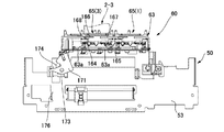
- FIG. 1 is a longitudinal sectional view showing the entire configuration of the ink jet printer according to the present embodiment.
- the inkjet printer 1 (hereinafter sometimes referred to simply as the “printer 1”) is provided with a roll paper loading unit 2, and the roll paper loading unit 2 takes up the long recording paper P in a roll shape.
- the roll paper 3 of the above configuration is loaded.
- a recording paper transport path 5 is formed from the roll paper loading unit 2 to the paper discharge port 4 formed on the front of the printer.
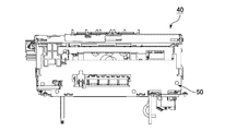
- a delivery roller 6, a sheet guide 7, a transport roller pair 8, and a platen 9 are disposed from the upstream side to the downstream side in the recording sheet transport direction. Further, the inkjet head 11 mounted on the head carriage 10 is disposed. The head carriage 10 moves the nozzle surface 11 a of the inkjet head 11 to the printing position of the recording paper conveyance path 5 facing the platen 9 and the home position deviated from the recording conveyance path 5. A maintenance device 40 described later is disposed at the home position.
- the transport roller pair 8 includes a drive roller 8a and a driven roller 8b.
- the drive roller 8 a is rotationally driven in the forward and reverse directions by the paper feed motor 12.
- Ink is supplied to the ink jet head 11 from an ink cartridge 14 mounted in the ink cartridge mounting portion 13.
- ink cartridge 14 mounted in the ink cartridge mounting portion 13.
- four color inks of black, cyan, magenta, and yellow are supplied to the inkjet head 11.
- the inkjet head 11 is a line-type inkjet head.
- the recording paper P fed from the roll paper 3 loaded in the roll paper loading unit 2 is transported along the recording paper transport path 5. Printing is performed by the inkjet head 11 on the recording paper P conveyed on the platen 9. The recording paper P after printing is discharged forward from the paper discharge port 4 on the front of the printer.
- FIG. 2A is an explanatory view showing the positional relationship between the printing position of the inkjet head 11 and the home position when the printer 1 is viewed from above
- FIG. 2B is the printing position and home position when the printer 1 is viewed from the front It is explanatory drawing which shows the positional relationship of.
- the inkjet head 11 is a line-type inkjet head composed of a plurality of inkjet heads.
- the first head 11A and the second head 11B are provided.
- Each ink nozzle row of the first and second heads 11A and 11B has a length capable of covering the width direction of the printing area of the recording paper P (the width in the direction orthogonal to the conveyance direction of the recording paper P).
- the first and second heads 11A and 11B of the line-type inkjet head are mounted on the carriage 10 with their nozzle faces 11a facing downward.
- the carriage 10 is horizontal, the nozzle surface 11 a is horizontal downward.
- a platen gap G having a preset size is formed.
- a maintenance device 40 is disposed on the side of the platen 9.
- the carriage 10 moves the ink jet head 11 to a printing position A facing the platen 9 and a home position B completely away from the recording paper conveyance path 5 (a position shown by a dashed dotted line in FIGS. 2A and 2B).
- the nozzle surface 11 a of the inkjet head 11 faces the maintenance device 40.
- the inkjet head 11 is in a horizontally oriented posture in which the longitudinal direction is directed in a direction perpendicular to the conveyance direction of the recording paper P. In this state, the ink nozzle row of each color provided in the first and second heads 11A and 11B covers the width direction of the printing area of the recording paper P.
- the inkjet head 11 is turned by 90 degrees from the attitude at the printing position A, and is in the attitude directed to the direction. That is, the ink jet head 11 has a vertically oriented posture in which the longitudinal direction thereof matches the transport direction.
- FIG. 3 is an explanatory view showing a movement locus of the carriage 10 on which the ink jet head 11 is mounted.
- the printer 1 positions and stops the inkjet head 11 at the printing position A, and performs printing on the recording paper P by performing an ink discharge operation every time the recording paper P is transported in this state by a predetermined pitch.
- the printer 1 retracts the ink jet head 11 to the home position B which is separated from the top of the platen 9 and stands by at the home position B.
- the maintenance device 40 While the inkjet head 11 is waiting, the maintenance device 40 performs a maintenance operation to prevent or eliminate clogging of the ink nozzles of the inkjet head 11.
- the maintenance device 40 lifts a cap provided at the upper end thereof to cap the nozzle surface 11 a.
- the ink discharge operation (flushing) is performed from the ink nozzles of the ink jet head 11 into the cap of the maintenance device 40.
- the maintenance device 40 performs an operation of sucking the ink from the cap.
- the maintenance device 40 is provided with a wiper for wiping the nozzle surface 11 a. When resuming printing, the ink jet head 11 is moved to the printing position A after the cap and the wiper retract downward.
- FIG. 4 is an explanatory view showing the nozzle surface 11 a of the ink jet head 11.
- the first head 11A includes four head units 1-1 to 1-4 including black and cyan ink nozzle arrays.
- the four head units 1-1 to 1-4 are arranged in two rows of two each along the direction of the ink nozzle row. Between each row, the head units 1-1 to 1-4 are arranged in a staggered manner.
- the second head 11B includes four head units 2-1 to 2-4 provided with yellow and magenta ink nozzle arrays.
- the four head units 2-1 to 2-4 are arranged in two rows of two each along the direction of the ink nozzle row. Between each row, the head units 2-1 to 2-4 are arranged in a staggered manner.
- the cap arrangement state of the maintenance device 40 described later is set to correspond to the arrangement state of the eight head units 1-1 to 1-4 and 2-1 to 2-4.
- the nozzle surfaces 1-1a to 1-4a of the head units 1-1 to 1-4 and the nozzle surfaces 2-1a to 2-4a of the head units 2-1 to 2-4 are head cover surfaces, respectively. It is surrounded by 10b.
- the head cover surface 10 b is surrounded by the lower surface portion 10 of the carriage 10.
- the nozzle surface 11a of the inkjet head 11 is a generic name of these nozzle surfaces 1-1a to 1-4a and 2-1a to 2-4a.
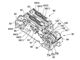
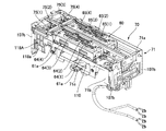
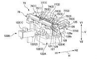
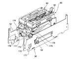
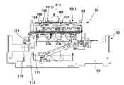
- FIG. 5A is a perspective view showing the maintenance device 40 taken out and FIG. 5B is a side view thereof.
- FIG. 6 is an exploded perspective view showing the main part of the maintenance device 40.
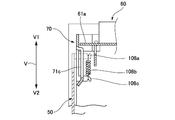
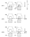
- the capping direction V the moving direction of the cap for capping the nozzle surfaces 1-1a to 1-4a
- the capping direction V1 the direction in which the cap approaches the nozzle surface
- the capping release direction V2 reverse The direction in which the cap moves away from the nozzle surface.
- the moving direction of the wiper for wiping the nozzle surfaces 1-a to 1-4a is referred to as a wiper moving direction H, and in the wiping movement direction H, the moving direction for the wiper when wiping the nozzle surface is a wiping direction H2
- the direction H2), the direction opposite to the wiping direction, is called H1 (wiper advancing direction H1).
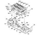
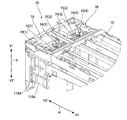
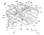
- the maintenance device 40 has a rectangular parallelepiped shape as a whole, and includes an apparatus frame 50, a cap unit 60, a wiper unit 70, an ink suction pump 94, a cap drive transmission mechanism 80, and a wiper / pump drive transmission mechanism 90. ing. A cap unit 60, an ink suction pump 94, a cap drive transmission mechanism 80, and a wiper pump drive transmission mechanism 90 are assembled to the apparatus frame 50.
- the apparatus frame 50 includes a rectangular bottom plate 51, and side plates 52 and 53 and end plates 54 and 55 which are respectively erected from the long side edge and the short side edge on both sides of the bottom plate 51.
- Two guide posts 56 a and 56 b are vertically attached to the bottom plate 51 of the device frame 50.
- the cap unit 60 is movable along the guide posts 56a, 56b.
- the cap drive transmission mechanism 80 moves the cap unit 60 in the direction along the guide posts 56a and 56b, that is, in the cap movement direction V (the capping direction V1 and the capping removal direction V2).
- the cap unit 60 has a number (eight) of caps 64 (1) to 64 (4), 65 (1) to 65 (8) corresponding to the head units 1-1 to 1-4 and 2-1 to 2-4. 4) is installed.
- the nozzle surfaces 1-1a to 1-4a of the head units 1-1 to 1-4 and 2-1 to 2-4 by the caps 64 (1) to 64 (4), 65 (1) to 65 (4), 2-1a to 2-4a (see FIG. 4) are capped.
- the ink suction pump 94 sucks the ink from each of the caps 64 (1) to 64 (4) and 65 (1) to 65 (4). Therefore, the ink is sucked from the ink nozzles of the head units 1-1 to 1-4 and 2-1 to 2-4 in the capping state.
- the suctioned ink is collected, for example, in a waste ink tank (not shown) provided in the ink cartridge 14.
- the wiper unit 70 includes four wipers 75 (not shown) that wipe the nozzle surfaces 1-1a to 1-4a and 2-1a to 2-4a of the head units 1-1 to 1-4 and 2-1 to 2-4. 1) to 75 (4) are installed.
- the wiper 75 (1) wipes the nozzle surfaces 1-1a, 1-3a of the head units 1-1, 1-3, and the wiper 75 (2) is the nozzle surface 1- of the head units 1-2, 1-4.
- the wiper 75 (3) wipes the nozzle surfaces 2-1a and 2-3a of the head units 2-1 and 2-3, and the wiper 75 (4) wipes the head unit 2-2, Wiping 2-4 nozzle faces 2-2a and 2-4a.
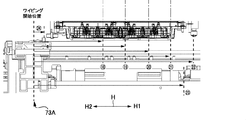
- the wipers 75 (1) to 75 (4) reciprocate in the wiper movement direction H which is a direction along the long side direction of the maintenance device 40.
- the wiper movement direction H is a direction parallel to the ink nozzle row of the inkjet head 11 located at the home position B.
- the wiper pump drive transmission mechanism 90 includes a drive motor 91 for driving the wiper unit 70 and the ink suction pump 94.
- the wiper and pump drive transmission mechanism 90 is provided with a drive switching mechanism 100 (see FIG. 8A).
- the drive switching mechanism 100 operates the wiper and pump drive transmission mechanism 90 according to the movement position of the cap unit 60 and accordingly the movement positions of the caps 64 (1) to 64 (4) and 65 (1) to 65 (4). , Switching the wiper to either the movable state or the driveable state of the suction pump.
- the cap unit 60 includes a cap frame 61, and first and second cap bases 62 and 63 (cap support members) fixed to the cap frame 61. .
- caps 64 (1) to 64 (4) are mounted on the first cap base 62, and four caps 65 (1) to 65 (4) are mounted on the second cap base 63.
- caps 64 (1) to 64 (4) will be referred to as “caps 64” and the caps 65 (1) to 65 (4) will be referred to as “caps 65”.
- the caps 64 (1) to 64 (4) have the same shape, and the nozzle surfaces 1-1a to 1-4a and 2-1a to 2 of the head units 1-1 to 1-4 and 2-1 to 2-4. And-provided with an elongated rectangular contour lip (cap opening edge) capable of concealing 4a.
- the caps 64 (1), 64 (3) are arranged at regular intervals along their length.
- the caps 64 (2), 64 (4) are also arranged at regular intervals along their length.
- the caps 64 (1) and 64 (3) constituting one cap row and the caps 64 (2) and 64 (4) constituting the other cap row are mutually arranged in a staggered manner. It is done.
- Each of the caps 64 (1) to 64 (4) is supported by the first cap base 62 via a pair of spring members 62a (cap pressing members), for example, a pair of compression coil springs (see FIG. 18A, which will be described later). See FIG. 22A).
- the pair of spring members 62 a is disposed between the end portions on both sides in the longitudinal direction of each of the caps 64 (1) to 64 (4) and the bottom plate portion of the first cap base 62.
- the caps 65 (1) to 65 (4) mounted on the second cap base 63 have the same shape as the caps 64 (1) to 64 (4), and are arranged in the same arrangement as these. .
- Each of the caps 65 (1) to 65 (4) is supported by the second cap base 63 via a pair of spring members 63a (cap pressing members), for example, a pair of compression coil springs.
- the pair of spring members 63a are disposed at both ends in the lengthwise direction of the respective caps 65 (1) to 65 (4).
- the caps 64 (1) to 64 (4) cap the head units 1-1 to 1-4 of the first head 11A of the ink jet head 11 shown in FIG.
- the caps 65 (1) to 65 (4) cap the head units 2-1 to 2-4 of the second head 11B shown in FIG.
- the cap diagonal peeling mechanism 160 is attached to the cap unit 60 (see FIGS. 18A to 18C and the like).
- the cap diagonal peeling mechanism 160 is provided for each of the caps 64 (1) to 64 (4) and 65 (1) to 65 (4) with the nozzle surface 1 of the head units 1-1 to 1-4 and 2-1 to 2-4.
- the lip surface end face of the cap opening edge
- the lip surface is inclined with respect to the nozzle surface.
- the wiper unit 70 includes a wiper frame 71 having a rectangular frame shape. At both ends in the short side direction of the wiper frame 71, a pair of guide shafts 72 is bridged in parallel in the long side direction of the wiper frame 71.
- the wiper holder unit 73 is disposed so as to be slidable along the pair of guide shafts 72.
- the wiper holder unit 73 is slidable along the guide shaft 72 from the home position 73A to the opposite end of the wiper unit 70.
- the wiper movement direction H is the movement direction of the wiper holder unit 73 defined by the guide shaft 72.
- wiper holders 74 (1) to 74 (4) are mounted in the wiper holder unit 73.
- One wiper 75 (1) to 75 (4) is mounted on each of the wiper holders 74 (1) to 74 (4).
- the wiper holders 74 (1) to 74 (4) will be referred to as “wiper holders 74" and the wipers 75 (1) to 75 (4) will be referred to as "wipers 75" as necessary.
- the wiper 75 (1) wipes the nozzle surfaces of the two head units 1-1 and 1-3 in the outer row of the first head 11 A shown in FIG.
- the wiper 75 (2) wipes the nozzle faces of the remaining two head units 1-2, 1-4.
- the wiper 75 (3) wipes the two head units 2-1, 2-3 in the inner row of the second head 11B shown in FIG.
- the wiper 75 (4) wipes the remaining two head units 2-2, 2-4.
- FIG. 7A and 7B show a cap drive transmission mechanism 80 for moving the cap unit 60.
- FIG. 7A is an exploded perspective view of the apparatus frame 50 with the side plates 52 and 53 omitted
- FIG. 7B is a perspective view of the apparatus frame 50 with the cap unit 60 assembled.
- the cap drive transmission mechanism 80 includes a pair of spiral cams 81 a and 81 b attached to the device frame 50.
- the spiral cams 81a and 81b are disposed adjacent to the guide posts 56a and 56b.
- the spiral cams 81 a and 81 b are supported by the bottom plate 51 so as to be rotatable around a central axis perpendicular to the bottom plate 51.
- Spiral grooves are formed on the outer peripheral surfaces of the spiral cams 81a and 81b along the direction of the central axis.
- the upward side surfaces of the spiral groove are cam surfaces 82a and 82b which extend in the vertical direction at a predetermined pitch in a spiral shape.
- a pair of cam follower rollers 66 (only one roller 66 is shown in the figure) is rotatably mounted on the cap frame 61 of the cap unit 60.
- the roller 66 rests on the cam surfaces 82a and 82b in a freely rolling manner.
- a guide hole 85 (only one guide hole 85 is shown in the figure) is formed.
- Guide posts 56a and 56b are slidably passed through the guide holes 85, respectively.
- a motor 83 is disposed at one end of the bottom plate 51 in the long side direction. Instead of the motor 83, a motor disposed on the main body side of the ink jet printer 1 can also be used as a drive source.
- the rotational force of the motor 83 is transmitted to the spiral cams 81a and 81b via a belt-pulley type power transmission mechanism 84.
- the respective spiral cams 81a, 81b rotate synchronously about their central axis.
- the pair of spiral cams 81a and 81b is rotated.
- the roller 66 on the cap unit 60 side which rests on the spiral cam surfaces 82a, 82b, rolls along the cam surfaces 82a, 82b.
- the cap unit 60 is guided by the pair of guide posts 56a and 56b, and moves in the cap moving direction V, in the vertical direction of the printer in this example.
- the respective caps 64 (1) to 64 (4), 65 (1 ) To 65 (4) are capped from the lower side on the nozzle surfaces of the head units 1-1 to 1-4 and 2-1 to 2-4 of the ink jet head 11.
- the position of the cap movement direction V of the cap unit 60 is controlled based on the output of the position detector 86.
- the position detector 86 is, for example, a photointerrupter, and is disposed adjacent to the motor 83.
- the cap frame 61 of the cap unit 60 is provided with a detection piece 86 a.
- the output of the position detector 86 is switched. Based on this output, it can be seen that the cap unit 60 has reached the standby position.
- the position of the cap unit 60 can be controlled based on the output of the position detector 86 and the number of encoder pulses of a rotary encoder (not shown) built in the motor 83. That is, the positions of the caps 64 (1) to 64 (4) and 65 (1) to 65 (4) in the cap movement direction V can be known.
- FIG. 8A is a perspective view showing the wiper pump drive transmission mechanism 90 and the cap unit 60 assembled to the device frame 50, and a portion of the wiper pump drive transmission mechanism 90 and the side plates 52, 53 of the device frame 50. Is omitted.
- 8B and 8C are perspective views showing the wiper pump drive transmission mechanism 90, respectively.
- FIG. 8D is a skeleton diagram of the main part of the wiper-pump drive transmission mechanism 90
- FIGS. 8E and 8F are explanatory diagrams showing the operation of the drive switching mechanism 100.
- FIG. 9A is a perspective view showing a state in which the wiper and pump drive transmission mechanism 90 and the cap unit 60 are assembled to the device frame 50, and the side plates 52 and 53 of the device frame 50 are omitted.
- 9B and 9C are explanatory diagrams showing a power transmission path to the wiper side.
- FIG. 10 is a perspective view showing a state in which the wiper and pump drive transmission mechanism 90 and the cap unit 60 are assembled to the apparatus frame 50.
- the side plates 52 and 53 of the device frame 50 are omitted, and the wiper holder unit 73 of the wiper unit 70 is attached to the wiper and pump drive transmission mechanism 90.
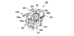
- the wiper pump drive transmission mechanism 90 includes a drive motor 91 attached to the bottom plate 51 as shown in FIGS. 8A to 8D.
- a motor mounted on the main body side of the ink jet printer 1 can also be used as a drive source.
- the rotation of the drive motor 91 is transmitted to the input shaft 93 a of the planetary gear reducer 93 via the transmission gear train 92.
- the planetary gear reducer 93 includes a sun gear 93d (see FIG. 8D) coaxially connected to or integrally formed with the input shaft 93a, a planetary gear 93e (see FIG. 8D) engaged with the sun gear 93d, and a planetary gear It includes an internal gear 93b meshing with 93e, and a planet carrier 93c rotatably supporting a planet gear 93e.
- an ink suction pump 94 is disposed coaxially.
- the rotation shaft (not shown) of the ink suction pump 94 is coaxially connected to the internal gear 93 b of the planetary gear reducer 93.
- the ink suction pump 94 is rotationally driven by the decelerated rotation taken out from the internal gear 93 b to perform the ink suction operation.
- a drive side external gear 93f is coaxially integrally formed on the planet carrier 93c.
- the drive side external gear 93f is connected to the drive side sprocket 96 for driving the belt via the transmission external gear 95a and the driven side external gear 95b.
- the drive side sprocket 96 is rotationally driven by the decelerating rotation taken out from the planet carrier 93 c.
- One longitudinal end of the wiper frame 71 of the wiper unit 70 is the home position 73 A of the wiper holder unit 73.
- the driven sprocket 97 is rotatably attached to the end of the wiper frame 71 on the home position 73A side.
- a drive belt 98 is stretched between the drive side sprocket 96 and the driven side sprocket 97.
- a slider 99 is fixed to the drive belt 98.
- an engagement hole 73a engaged with a protrusion 99a formed on the slider 99 is formed.
- the wiper holder unit 73 engaged with the slider 99 moves in the wiper moving direction H.
- the four wipers 75 (1) to 75 (4) mounted on the wiper holder unit 73 make head units 1-1 and 1-3, head units 1-2 and 1-4, and head unit 2-1, The nozzle surfaces of the head unit 2-3 and the head units 2-2 and 2-4 can be wiped respectively.
- the wiper drive transmission mechanism in the wiper pump drive transmission mechanism 90 will be described in more detail with reference to FIGS. 9A, 9B and 9C.
- the wiper drive transmission mechanism portion has a drive side external gear 93 f and a transmission external gear 95 a mounted on the apparatus frame 50, and a driven external gear 95 b mounted on the wiper frame 71.
- the transmission external gear 95a meshes with both the drive external gear 93f and the driven external gear 95b.
- the transmission external gear 95 a is rotatably supported by the tip of the revolving frame 201.
- the proximal end of the swing frame 201 is supported by the cover 90A of the wiper and pump drive transmission mechanism 90 so as to be able to swing around the central axis of the drive side external gear 93f. Therefore, the transmission external gear 95a can revolve around the central axis of the drive external gear 93f while maintaining the meshing state with the drive external gear 93f.
- a connecting plate 202 is bridged between the shaft portion of the transmission external gear 95a and the shaft portion of the driven external gear 95b. Therefore, the transmission external gear 95a and the driven external gear 95b are always held in mesh.
- the wiper unit 70 is supported by the device frame 50 so as to be movable in the cap movement direction V. In addition, it is pressed in the capping direction V1 by the tension coil spring 108b, and is in a floating state from the apparatus frame 50.
- the driven external gear 95b on the wiper frame 71 side also moves in the same direction.
- the transmission external gear 95a meshing with the driven external gear 95b maintains meshing with the driven external gear 95a as the driven external gear 95b moves.
- the power for moving the wiper can be transmitted from the side of the device frame 50 to the side of the wiper frame 71 regardless of the movement of the wiper frame 71. According to this configuration, it is not necessary to mount all the parts constituting the wiper drive transmission mechanism on the moving wiper frame 71, which is advantageous for reducing the weight of the wiper unit 70.
- the drive-side external gear 93f of the wiper drive transmission mechanism portion is stopped.
- the transmission gear 95a meshing with the drive side external gear 93f revolves around the central axis of the drive side external gear 93f while rotating. Therefore, the driven external gear 95b engaged with the transmission gear 95a also rotates.
- the wiper holder unit 73 mounted on the drive belt 98 slightly moves in the wiper movement direction H.
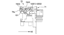
- the direction indicated by the arrow H2 is the wiping direction, but it moves slightly in the opposite direction H1.
- the wiper holder unit 73 is slightly moved in the direction opposite to the wiping direction H2. That is, the wipers 75 (1) to 75 (4) move slightly in the direction H1 opposite to the wiping direction H2.
- the wipers 75 (1) to 75 (4) moves in a direction slightly inclined to the direction H1 opposite to the wiping direction H2 with respect to the direction perpendicular to the nozzle surface. Such movement of the wiper can prevent foreign matter such as ink from the wiper from being scattered around as described later.
- the drive switching mechanism 100 is attached to the wiper and pump drive transmission mechanism 90, and it is possible to switch between the wiper drivable state and the pump drivable state.
- the drive switching mechanism 100 performs switching operation according to the movement position of the cap unit 60. Therefore, the switching operation is performed according to the movement position of the caps 64 (1) to 64 (4) and 65 (1) to 65 (4).
- the planetary gear reducer 93 When the cap unit 60 moves from the standby position by a predetermined amount in the capping direction V1, the planetary gear reducer 93 has a state in which the internal gear 93b is rotatable and the planetary carrier 93c can not rotate. In this state, the decelerated rotation is output from the internal gear 93b. Therefore, the suction pump 94 connected to the internal gear 93b is driven, and the ink suction operation from each of the caps 64 (1) to 64 (4) and 65 (1) to 65 (4) becomes possible.
- the planetary gear reducer 93 can not rotate the internal gear 93b.
- the planet carrier 93c is rotatable. In this state, the decelerating rotation is output from the planet carrier 93c.
- the wipers 75 (1) to 75 (4) mounted on the wiper holder unit 73 connected to the planet carrier 93c can be moved. Therefore, the wiping operation of the nozzle surfaces of the head units 1-1 to 1-4 and 2-1 to 2-4 becomes possible.
- the drive switching mechanism 100 includes a first latch mechanism 102 that latches the internal gear 93b in a non-rotatable state by the spring force of the first tension coil spring 101, and the second latch mechanism 102.
- the second latch mechanism 104 latches the planetary carrier 93 c in a non-rotatable state by the spring force of the tension coil spring 103.
- the first latch mechanism 102 includes a first latch lever 102a
- the second latch mechanism 104 is a second latch disposed at a position (position on the side of the capping direction V1) in the figure above the first latch lever 102a.
- the lever 104a is provided.
- the cap frame 61 of the cap unit 60 is provided with a first cam surface 105 which can be pushed against the spring force of the first latch lever 102a by the movement of the cap unit 60 at a position facing the first latch lever 102a. It is done.
- a second cam surface 106 is formed on the cap frame 61 at a portion facing the second latch lever 104a so that the second latch lever 104a can be pushed against the spring force by the movement of the cap unit 60.
- the first and second cam surfaces 105 and 106 are formed at different positions in the cap movement direction V.
- the first latch lever 102a When the first latch lever 102a is pushed against the spring force, the latch by the first latch mechanism 102 is released, and the internal gear 93b switches to a rotatable state.
- the second latch lever 104a Conversely, when the second latch lever 104a is pushed against the spring force, the latch by the second latch mechanism 104 is released, and the planet carrier 93c is switched to the rotatable state.
- the wiper / pump drive transmission mechanism 90 is switched by the drive switching mechanism 100 between the pump drive enable state and the wiper drive enable state according to the movement position of the cap unit 60 in the cap movement direction V.
- the switching timing etc. can be easily adjusted or changed by changing the engagement position of the latch lever and the cam surface in the cap moving direction V. Therefore, compared with the mechanism which switches a power transmission direction using members, such as a cylindrical cam and an intermittent gear, a small, compact and easy switching mechanism is realizable.
- the nozzle surface when the nozzle surface is long in the nozzle row direction, as in the case of a line-type inkjet head, the nozzle surface may not be wiped at a constant wiping pressure.
- the maintenance device may be inclined relative to the nozzle surface of the ink jet head in the nozzle row direction (wiper movement direction). In this case, the pressing force of the wiper against the nozzle surface fluctuates during wiping, and the nozzle surface of each head unit can not be wiped with a constant wiping pressure.
- the wiper unit 70 of this example is supported by the device frame 50 as follows.
- FIG. 11A is a perspective view showing the cap unit 60 with the wiper unit 70 assembled.
- FIG. 11B is a partially enlarged perspective view showing a part of the side surface.
- FIG. 11C is an explanatory view showing the relationship between the device frame 50, the cap unit 60 and the wiper frame 71.
- the wiper unit 70 is supported by the device frame 50 in a state of being pulled up (pressed) by a spring force in the capping direction.
- guide portions 107a protruding in the capping direction V1 are formed at four corners of the device frame 50.
- the four corners of the wiper frame 71 of the wiper unit 70 are guide portions 107b which are guided in the cap movement direction V along the inner side surface of the guide portion 107a.
- a spring hook 108a is formed at the upper end edge of the guide portion 107a of the apparatus frame 50.
- One end of a tension coil spring 108b is hooked on each spring hook 108a.
- Spring hooks 108 c are formed at inner portions of the four corners of the wiper frame 71. The lower end of each tension coil spring 108b is hooked on the spring hook 108c.
- the wiper unit 70 is held movable relative to the apparatus frame 50 in the cap movement direction V. Further, it is attached to the apparatus frame 50 in a floating state by four tension coil springs 108b. That is, the wiper unit 70 is always pushed upward (in the capping direction) by the tension coil spring 108b, and it is possible to push the wiper unit 70 downward (in the capping release direction) against the spring force of the tension coil spring 108b.
- a restricting portion is provided between the device frame 50 and the wiper frame 71 of the wiper unit 70 to restrict the upper position of the wiper unit 70 (the position in the capping direction V1).
- the end plate 54 of the device frame 50 is formed with a pair of engagement protrusions 109a.
- the wiper frame 71 is formed with a pair of engagement frames 109b through which the respective engagement protrusions 109a are inserted.
- the other end plate 55 of the device frame 50 is also formed with an engagement protrusion 109c.
- the wiper frame 71 is formed with an engagement frame 109d into which the engagement protrusion 109c is inserted.
- the wiper unit 70 supported in a floating state on the device frame 50 moves with the cap unit 60 in a predetermined range in the cap movement direction V.
- the side plate portions 71b on both sides of the wiper frame 71 of the wiper unit 70 are formed with rectangular frame portions 71c set back to the inside.
- a pair of engaging protrusions 61a are formed to project laterally.
- the wiper unit 70 pulled up by the tension coil spring 108b does not move.
- the engagement protrusion 61a engages with the rectangular frame portion 71c. Thereafter, the wiper unit 70 is forced to move in the capping release direction V2 integrally with the cap unit 60.
- the wiper unit 70 moves in the capping direction together with the cap unit 60 by the spring force of the tension coil spring 108b.
- the engagement protrusion 61a of the cap unit 60 is separated from the rectangular frame portion 71c of the wiper frame 71 in the capping direction V1, as shown in FIG. 11B. Therefore, the wiper unit 70 is held at a predetermined position by the engagement between the engagement protrusions 109a and 109c and the engagement frames 109b and 109d by the spring force of the tension coil spring 108b.
- an abutting surface 71a is formed at a position one step higher along the long side edges on both sides thereof.
- the contact surface 71a is closer to the lip surface (end face of the cap opening edge) of the caps 64 (1) to 64 (4) and 65 (1) to 65 (4).
- the wiper unit 70 on which the wipers 75 (1) to 75 (4) are mounted is mounted on the apparatus frame 50 in a so-called floating state.
- the wiper unit 70 is disengaged from the cap unit 60 and is pressed in the capping direction V1 by the spring force of the tension coil spring 108b.
- the caps 64 (1) to 64 (4) and 65 (1) to 65 (4) of the cap unit 60 abut on the nozzle surface 11 a of the inkjet head 11
- the abutment surface 71 a of the wiper frame 71 of the wiper unit 70 Contact the lower surface of the carriage 10 on the side of the inkjet head 11.
- the wiper unit 70 is positioned with respect to the nozzle surface 11 a of the inkjet head 11. Even if the inkjet head 11 is inclined relative to the maintenance device 40, the wiper unit 70 follows the inclined attitude of the inkjet head 11.
- the plurality of wipers 75 (1) to 75 (4) mounted on the wiper unit 70 correspond to the nozzles of the head units 1-1 to 1-4 and 2-1 to 2-4 of the corresponding inkjet head 11. It is positioned at a fixed distance with respect to the surface.
- the wipers 75 (1) to 75 (4) can be pressed against the nozzle surfaces with a constant wiping pressure, and the nozzle surfaces can be reliably wiped in an appropriate pressing state. That is, in a state where the contact surface 71a of the wiper frame 71 contacts the lower surface of the carriage 10, the wipers 75 (1) to 75 (4) are raised to the upright position as described later. In this state, when the wipers 75 (1) to 75 (4) are moved in the wiping direction H2, the head units 1-1 to 1 constituting the ink jet head 11 have constant pressure at their leading edge portions. It becomes possible to press the nozzle surfaces 1-1a to 1-2a and 2-1a to 2-4a.
- a selective suction mechanism for selectively suctioning each of the plurality of caps 64 (1) to 64 (4), 65 (1) to 65 (4) individually using the suction pump 94.
- a selective suction mechanism is provided to selectively suction.
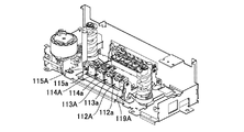
- FIGS. 12A to 12D are explanatory views showing a selective suction mechanism.
- a selective suction mechanism for selecting the caps 65 (1) to 65 (4) is disposed on the side of one side surface 52 of the device frame 50.
- a selective suction mechanism for selecting the caps 64 (1) to 64 (4) is disposed on the side of the other side surface 53. Since both selective suction mechanisms have basically the same configuration, the selective suction mechanism for selecting the caps 64 (1) to 64 (4) will be described.
- the suction tube 110 (see FIG. 11A) branched into four from the suction port and the side of the side plate 53 in the device frame 50 It communicates with the four valves 112A to 115A arranged in FIG.
- the valves 112A to 115A are, for example, normally closed valves that are always kept in a closed state by a built-in diaphragm (not shown).
- valves 112A to 115A are pushed in, the diaphragm is displaced and switched to the open state.
- the elastic return force of the diaphragm returns to the closed state again.
- the valves 112A to 115A are arranged along the wiper movement direction H.
- the valves 112A to 115A are opened, the ink suction passage for sucking the ink from the caps 64 (1) to 64 (4) is opened, and the ink suction pump 94 can suction ink.
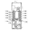
- a guide shaft 116a extending in the wiper movement direction H is disposed along the upper edge of the window.
- a valve selector 117A is disposed slidably along the guide shaft 116a and a guide rail 116b defined by the lower edge of the window.
- the valve selector 117A is movable along the guide shaft 116a to a position facing the opening / closing levers 112a to 115a of the valves 112A to 115A.
- the valve selector 117A includes an engagement protrusion 117a protruding in the capping direction along the outer surface of the side plate 53, and a lever pushing protrusion 117b protruding inward of the side plate 53.
- a selector hook 118A protruding in the capping release direction V2 is attached on the side surface of the wiper holder unit 73 moving in the wiper movement direction H.
- the selector hook 118A is formed with an engagement recess 118a having a shape complementary to the engagement protrusion 117a.
- the engagement protrusion 117a of the valve selector 117A can be inserted into the engagement recess 118a in the capping direction.
- the wiper holder unit 73 can move the valve selector 117A in the wiper movement direction H along the guide shaft 116a.
- the selector hook 118A is positioned on the valve selector 117A.
- the cap unit 60 is moved in the capping release direction V2 by a predetermined amount.
- the wiper unit 70 also moves in the same direction, and the selector hook 118A of the wiper unit 70 engages with the valve selector 117A.
- the valve selector 117A is positioned in the wiper moving direction H with respect to one of the valves 112A to 115A.
- the opening / closing levers 112a to 115a of the valves 112A to 115A, in which the valve selector 117A is positioned, are held at the open position by the lever pushing projection 117b of the valve selector 117A. Therefore, the ink suction operation can be performed by the suction pump 94 from the corresponding caps 65 (1) to 65 (4) through the valves 112A to 115A held in the open state.
- the selection operation of the valves 112A to 115A for performing the selective suction operation can be realized by the movement of the cap unit 60 (cap) in the cap movement direction V and the movement of the wiper holder unit 73 (wiper) in the wiper movement direction H. Therefore, the selective suction operation can be realized with a small and compact configuration without using a component for selective switching such as a cylindrical cam, an intermittent gear, or a swing member.
- a valve full opening lever 119A is attached to the device frame 50.
- the valve full opening lever 119A can push in the opening and closing levers 112a to 115a of the valves 112A to 115A simultaneously.
- the valve selector 117A is positioned adjacent to the opening / closing lever 112a in the wiper movement direction H. In this position, the valve fully opening lever 119A is pushed in by the lever pushing projection 117b of the valve selector 117A.
- valve fully open lever 119A When the valve fully open lever 119A is pushed, the open / close levers 112a to 115a of the valves 112A to 115A are simultaneously pushed by the valve fully open lever 119A. Thereby, all the valves 112A to 115A are switched to the open state.
- the ink suction operation from all the caps 64 (1) to 64 (4) that is, the ink from the head units 1-1 to 1-4 capped by them Suction can be performed simultaneously.
- valve selector 117A When the valve selector 117A is positioned at a position deviated from the valves 112A to 115A and the valve full opening lever 119A, the valves 112A to 115A are held in a fully closed state.
- the lever pushing projection 117b interferes with the opening and closing levers 112a and 115a of the valves 112A to 115A.
- the cap unit 60 is formed with a lever pushing projection.
- the side plate portion 61 b of the cap frame 61 of the cap unit 60 is formed with a lever pushing protrusion 61 c that protrudes inward.
- the position of the lever pushing protrusion 61c is set as follows in the cap moving direction V.
- the lever pushing protrusion 61c reaches a position where the valve fully open lever 119A can be pushed.
- valve selector 117A In the state where the valve selector 117A is slid along the guide rail 116, the open / close levers 112a to 115a of the valves 112A to 115A are pushed by the valve fully open lever 119A to cause the valve selector 117A to interfere with the open / close levers 112a to 117a. It can slide without.
- the mechanism for selectively suctioning the other cap 65 (1) to 65 (4) is also configured as described above.
- the shapes of the valve selectors on both sides are slightly different so that each of the caps 64 (1) to 64 (4) and 65 (1) to 65 (4) can be selectively suctioned individually.
- valves disposed on the side of the side plate 52 for selecting the caps 65 (1) to 65 (4), the valve selector, the selector hook, and the valve full opening lever are respectively valves 112B to 115B, The valve selector 117B, the selector hook 118B, and the valve fully open lever 119B are used.
- the engagement protrusion 117a of the other valve selector 117B is shorter than the engagement protrusion 117a of one valve selector 117A.
- the valve selectors 117A and 117B move in the capping release direction V2, they engage with the selector hooks 118A and 118B, respectively (ST1 in FIG. 12D).
- the wiper holder unit 73 is moved in the wiper movement direction H, and for example, the valve selector 117B provided with the short engagement protrusion 117a is moved to the target valve position in the wiper movement direction H.
- the other valve selector 117A also moves to the same position together.
- both valve selectors 117A and 117B After the target valve position is selected by both of the valve selectors 117A and 117B, the cap unit 60 is moved in the capping direction. As a result, both valve selectors 117A and 117B are disengaged from the selector hooks 118A and 118B (ST3 in FIG. 12D).
- the cap to be suctioned with ink can be freely selected from the caps 64 (1) to 64 (4) on one side.
- the cap for the ink suction can be freely selected from the caps 65 (1) to 65 (4) on the other side without being influenced by the selection operation of the caps 64 (1) to 64 (4).
- Wiper selection mechanism of the wiper unit 70 In general, in the case of an ink jet head composed of a plurality of head units, it is desirable to wipe the head unit requiring maintenance. If such selective wiping can be realized by a compact and compact mechanism, it is advantageous for downsizing and cost reduction of the maintenance device.
- the nozzle surfaces 1-1a to 1-4a, 2 of the head units 1-1 to 1-4 and 2-1 to 2-4 of the ink jet head 11 are described.
- Four wipers 75 (1) to 75 (4) are provided to wipe the areas 1a to 2-4a.
- the four wipers 75 (1) to 75 (4) are held in the state of the fallen position not to contact the head unit.
- the wiper unit 70 is provided with a wiper selection mechanism, and can set the wipers 75 (1) to 75 (4) in the fallen position to the upright position where they can be brought into contact with the head unit individually.
- the wipers 75 (1) to 75 (4) are raised to the upright position, wiping of the head units 1-1 to 1-4 and 2-1 to 2-4 becomes possible.
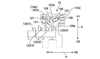
- FIG. 13 is a partial perspective view showing the wiper holder unit 73 of the wiper unit 70
- FIGS. 14A and 14B are a perspective view and a side view showing the wiper selection mechanism.
- 15A to 15C are explanatory views showing the wiper raising operation by the wiper raising member.
- 16A to 16C are explanatory views showing a wiper overturning operation by the wiper overturning member.
- the wiper holder unit 73 includes a slide frame 76 which can slide in the wiper movement direction H along the guide shafts 72 on both sides.
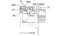
- a turning central axis 121 is bridged in a direction orthogonal to the wiper movement direction H.
- wiper holders 74 (1) to 74 (4) are attached to the turning center shaft 121 in the axial direction.
- Wipers 75 (1) to 75 (4) are attached to the wiper holders 74 (1) to 74 (4), respectively.
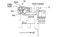
- the wiper holders 74 (1) to 74 (4) can be switched between the first state and the second state with the pivoting center axis 121 as the center. In this example, it is possible to turn from the state of the falling position 74A which is the first state shown in FIG. 15A to the state of the rising position 74B which is the second state shown in FIG. 15C.
- the wipers 75 (1) to 75 (4) are in the posture of falling in the direction along the wiper movement direction H, and the tip edge thereof faces the home position 73 A of the wiper holder unit 73.
- the wipers 75 (1) to 75 (4) are in the standing posture facing the capping direction V 1 along the cap movement direction V. In the standing posture, the wipers 75 (1) to 75 (4) protrude from the slide frame 76 in the capping direction V1.
- Position holding arms 77 (1) to 77 (4) are attached to the wiper holders 74 (1) to 74 (4).
- the position holding arms 77 (1) to 77 (4) stably hold the wiper holders 74 (1) to 74 (4) in two positions, the falling position 74A and the rising position 74B.
- the position holding arms 77 (1), 77 (4) of the wiper holders 74 (1), 74 (4) on both sides are disposed outside of them and the inner wiper holder 74 2), 74 (3) position holding arms 77 (2), 77 (3) are arranged inside them.
- the structure of the position holding arms 77 (1) to 77 (4) will be described with reference to FIG. 15A. Since the position holding arms 77 (1) to 77 (4) have the same structure, the structure will be described by taking the position holding arm 77 (4) as an example.
- a support shaft 125 is bridged over the slide frame 76 in parallel with the turning center shaft 121.
- the support shaft 125 is disposed on the side of the home position 73 A of the wiper holder unit 73 with respect to the pivoting center shaft 121.
- the position holding arm 76 (4) includes a compression coil spring 126, a link 127, and a link 128.
- the link 127 is integrally formed or fixed to the wiper holder 74 (4), and pivots integrally with the wiper holder 74 (4) about the pivot center axis 121.
- the link 128 is supported by the support shaft 125 so as to be pivotable about the support shaft 125.
- the distal end of the link 127 and the distal end of the link 128 are rotatably coupled with each other by the coupling pin 129.
- the link 128 is formed with an elongated shaft hole 128 a into which the support shaft 125 is inserted.
- the compression coil spring 126 always presses the link 128 toward the connecting pin 129 with respect to the support shaft 125.
- FIGS. 15A to 15C in order to turn the wiper holder 74 (4) from the fall position 74A to the upright position 74B, the compression coil spring 126 needs to be compressed. Conversely, also when the wiper holder 74 (4) is returned from the standing position 74B to the falling position 74A, the compression coil spring 126 needs to be compressed. As shown in FIG.
- the compression coil spring 126 is compressed most when the connecting pin 129 is positioned on a straight line connecting the center axis of pivoting 121 and the center of the support shaft 125. Therefore, the position holding arm 76 (4) is pressed by the spring force of the compression coil spring 126 toward either the falling position 74A or the rising position 74B with this position as the boundary.
- the wiper holder 74 (4) is stably held at any of these positions. That is, the wipers 75 (1) to 75 (4) are reliably held at the standing position during wiping, and wiping can be performed reliably. In addition, the wipers 75 (1) to 75 (4) in the fallen position do not stand up unnecessarily.
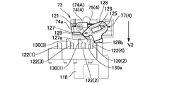
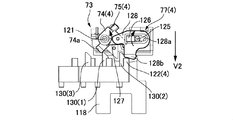
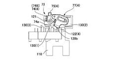
- a plurality of wiper raising members functioning as a wiper engaging member for switching the state of the wiper from the first state to the second state Is arranged.
- four wiper raising members 122 (1) to 122 (for use in raising each of the wiper holders 74 (1) to 74 (4) from the falling position 74A to the rising position 74B. 4) is arranged.
- the wiper raising members 122 (1) and 122 (2) vertically protrude from the top surface of the substrate 122A, and the wiper raising members 122 (3) and 122 (4) vertically protrude from the top surface of the substrate 122B.
- the substrates 122A and 122B are fixed to the upper surface of the cover 90A of the wiper pump drive transmission mechanism 90 having a predetermined height attached to the bottom plate 51 of the device frame 50.
- the wiper raising members 122 (1) to 122 (4) are disposed at different positions along the wiper movement direction H, as shown in FIGS. 10 and 14A. Further, in the width direction of the wiper unit 70 orthogonal to the wiper movement direction H, the wiper raising members 122 (1) to 122 (4) are the position holding arms 77 (1) of the wiper holders 74 (1) to 74 (4). ) To 77 (4). As shown in FIGS. 14A and 14B, the link 128 of each of the position holding arms 77 (1) to 77 (4) is formed with an engagement protrusion 128b projecting in the capping release direction V2.
- the wiper holder unit 73 is moved in the wiper movement direction H to the position where the wiper raising members 122 (1) to 122 (4) are disposed.
- the engagement protrusions 128b of the position holding arms 76 (1) to 76 (4) of the four wiper holders 74 (1) to 74 (4) are moved in the cap moving direction V by the corresponding wiper raising member 122.
- One of (1) to 122 (4) can be faced.
- the cap unit 60 is moved in the capping release direction V2.
- the wiper unit 70 is also moved in the capping release direction, and the engaging projection 128b hits one of the corresponding wiper raising members 122 (1) to 122 (4).
- FIG. 15A shows this state.
- the engagement protrusions 128b are relatively pushed up in the capping direction V1 by the wiper raising members 122 (1) to 122 (4).
- the position holding arms 77 (1) to 77 (4) are in a position where the wiper holders 74 (1) to 74 (4) are inclined against the spring force of the compression coil spring 126. Raise from 74 to the standing position 74B.
- the wiper holder unit 73 is moved in the wiper movement direction H and positioned at a position before the head units 21 to 24 and 31 to 34 to be wiped.
- the cap unit 60 is moved in the capping direction V1
- the wipers 75 (1) to 75 (4) that have stood up are the nozzle surfaces 21a to 24a and 31a to 34a of the head units 21 to 24 and 31 to 34. Set to a position where wiping is possible.
- the wiper holder unit 73 is moved along the wiper movement direction H, the corresponding head units 1-1 to 1-4, 2- can be moved by the wipers 75 (1) to 75 (4) mounted thereon. Wiping of the nozzle surfaces 1-1a to 1-4a and 2-1a to 2-4a of 1 to 2 is performed.
- the wiper is switched from the second state to the first state on the inner end face of the wiper holder unit 73 on the home position 73A side.
- a plurality of wiper lowering members that function as wiper engaging members are disposed.
- two wiper overturning members 123 (1) and 123 (2) extending in the wiper movement direction H are provided.
- the wiper overturning member 123 (1) is a member for lowering the wiper holders 74 (1) and 74 (2) from the upright position 74A to the downturned position 74B
- the wiper overturning member 123 (2) is the wiper holder 74 (3), 74.
- (4) is a member for falling from the standing position 74A to the falling position 74B.
- the wiper holders 74 (1) to 74 (4) are respectively formed with engagement protrusions 74a extending in the capping release direction.
- the engagement protrusions 74a of the wiper holders 74 (1) and 74 (2) are formed at adjacent positions.
- the engaging projections 74a move toward the home position 73A of the wiper holder unit 73 along the wiper movement direction H, they can simultaneously contact one wiper overturning member 123 (1).
- the respective engaging protrusions 74a of the wiper holders 74 (3) and 74 (4) are formed at adjacent positions, and can be simultaneously brought into contact with one wiper tilting member 123 (2).
- the wiper selection operation in other words, the selection operation of the head unit to be wiped
- one of the plurality of wipers 75 (1) to 75 (4) can be selected.
- the head units 21 to 24 and 31 to 34 can be selectively wiped.
- Three restriction members 130 (1) to 130 (3) are formed on the substrates 122A and 122B on which the wiper raising members 122 (1) to 122 (4) are formed.
- the restricting member 130 (1) prevents the wiper holder 74 (1) from pivoting to the upright position with the wiper holder 74 (2), and the restricting member 130 (3) causes the wiper holder 74 (3) to It prevents pivoting to the upright position with the holder 74 (4). Further, the restricting member 130 (4) prevents the wiper holder 74 (4) from pivoting to the upright position together with the wiper holder 74 (3).
- a restriction member for preventing the wiper holder 73 (1) from pivoting to the upright position together with the wiper holder 74 (2) is not shown.
- restricting members 130 (1) to 130 (3) protrude perpendicularly to the capping direction V 1 from the upper surfaces of the substrates 122 A and 122 B, and an engaging end face 130 a extending in the cap moving direction V is formed.
- the link 127 in each of the wiper holders 74 (1) to 74 (4) is formed with an engaging end face 127a extending in the cap moving direction V in the state of the falling position 74A.
- the engagement end face 127a of the link 127 of the wiper holder 74 (4) is a wiper relative to the engagement end face 130a of the regulating member 130 (2). Face each other with a slight gap from the moving direction H.
- the engagement end face 127a abuts on the engagement end face 130a of the regulating member 130 (2).
- the wiper holder 74 (3) does not pivot together with the wiper holder 74 (4) toward the standing position 74B.
- the wiper holders 74 (3) and 74 (4) stick to each other.
- the other wiper holder 74 (3) may be erected along with it.
- the restriction member 130 (2) can reliably prevent the non-selected wiper holder from rising.
- both end portions of the tip end portion of the wiper pressed against the nozzle surface are likely to be largely deformed.
- foreign matter such as ink can not be reliably wiped off from the portion of the nozzle surface that is in contact with both sides of the wiper tip edge.
- the flat wiper is bent in an arc to increase the rigidity, foreign substances such as ink adhering to the nozzle surface can be wiped off reliably on both sides of the front end of the wiper.
- the maintenance device 40 of this example is provided with a wiper and a wiper cleaner unit having the configuration described below.
- FIG. 17 is an explanatory view showing an end portion of the wiper unit 70 on the home position side.
- the wiper holder unit 73 When the wiper holder unit 73 is at the home position 73A, the four wipers 75 (1) to 75 (4) are tumbled by the wiper folding members 123 (1) and 123 (2) to be in the collapsed position. ing.
- the wiper 75 (4) is shown in the upright position and the wiper 75 (2) is shown in the middle of turning from the fallen position to the upright position in order to clearly show the wiper shape. It is
- the wiper 75 (1) is attached to the wiper holder 74 (1) in a state in which a flat rubber having a rectangular contour is bent in an arc shape.
- the wiper 75 (1) has a convex curved surface 75a, the wiping surface 75a facing in the wiping direction H2. Therefore, the tip edge 75b of the wiper 75 (1) sliding on the nozzle surfaces 1-1a and 1-3a of the head units 1-1 and 1-3 to be wiped is similarly bent in the wiping direction H2. It has the same shape.
- the wiper 75 (1) shaped into a circular arc so that the wiping direction H 2 is a convex curved surface has higher rigidity at the time of wiping than a flat wiper.
- both end sides of the tip edge portion are deformed significantly, and the nozzle surfaces 1-1a and 1-3a
- the curved tip edge 75b of the wiper 75 (1) slides along the nozzle surfaces 1-1a and 1-3a in a state where the respective portions uniformly abut on the nozzle surfaces 1-1a and 1-3a. Move. Therefore, appropriate wiping can be performed compared to a flat wiper.
- the other wipers 75 (2) to 75 (4) also have the same shape as the wiper 75 (1), so the description thereof is omitted.
- a wiper cleaner unit 150 is attached to the wiper unit 70.
- the wiper cleaner unit 150 includes a plate-like wiper cleaner 151.
- the wiper cleaner 151 is bridged in the direction of the short side of the wiper frame 71 on the upper surface of the wiper frame 71.
- the arrangement position of the wiper cleaner 151 is a position between the wiper holder unit 73 located at the home position 73A and the cap unit 60.
- cleaner support plates 152 and 153 extending in a direction H1 (forward direction of the wiper) opposite to the wiping direction H2 are integrally formed.
- the tip end portions of the cleaner support plates 152 and 153 are movable in the direction toward and away from the upper surface of the wiper frame 71 centering on the support shaft 154 (only one support shaft 154 is shown in the figure). , And is attached to the wiper frame 71.
- the cleaner support plates 152 and 153 are always pressed in the direction of being lifted from the upper surface of the wiper frame 71 by the rod-like spring member 155 supported on the wiper frame 71 side.
- the wiper cleaner 151 is in a state of being floated up at substantially the same height position as the contact surface 71 a of the wiper frame 71.
- concave end surfaces 151 (1) to 151 (4) (wiper cleaning surface) for wiper cleaning are formed at four positions.
- the concave end surfaces 151 (1) to 151 (4) have a shape corresponding to the curved shape of the tip end edge 75b of the wipers 75 (1) to 75 (4). Further, the concave end surfaces 151 (1) to 151 (4) are located on the movement locus of the leading edge 75b of the wipers 75 (1) to 75 (4) in the standing position.
- the wipers 75 (1) to 75 (4) wipe the nozzle surfaces 1-1a to 1-4a and 2-1a to 2-4a of the head units 1-1 to 1-4 and 2-1 to 2-4. After completion, the home position 73A is returned from the wiping end position. At this time, the wipers 75 (1) to 75 (4) pass the wiper cleaner 151. When passing the wiper cleaner 151, the leading edge 75b of each wiper 75 (1) to 75 (4) slides on each concave end surface 151 (1) to 151 (4). As a result, the ink etc. adhering to the leading edge 75 b of the wipers 75 (1) to 75 (4) are wiped off by the concave end faces 151 (1) to 151 (4).
- the wiper cleaner unit 150 includes a pair of ink recovery units 156 and 157 that recover the ink and the like wiped off by the wiper cleaner 151. As described with reference to FIG. 6, the ink recovery portions 156 and 157 are attached to one end of the first and second cap bases 62 and 63 in the cap unit 60.
- the ink recovery units 156 and 157 include plate-like ink absorbing materials 156 a and 157 a and mounting units 156 b and 157 b on which these are mounted.
- the abutment surfaces 71a on both sides of the wiper unit 70 abut the lower surface portion 10a (see FIG. 4) of the head carriage 10 surrounding the nozzle surface 11a of the inkjet head 11.
- the wiper cleaner 151 is disposed at a position adjacent to the head carriage 10, and the wiper cleaner 151 also hits the lower surface portion 10 a of the head carriage 10. As a result, the wiper cleaner 151 is pushed into the wiper frame 71 side.
- the portions including the concave end surfaces 151 (1) to 151 (4) are in a state of being pressed against the ink absorbents 156a and 157a of the ink recovery portions 156 and 157.
- foreign substances such as ink adhering to the concave end faces 151 (1) to 151 (4) of the wiper cleaner 151 are absorbed by the ink absorbing materials 156a and 157a and recovered.
- the wiper cleaner 151 When the cap unit 60 is returned from the capping state to the standby position, the wiper cleaner 151 is separated from the lower surface portion 10 a of the head carriage 10. As a result, it returns to the state of being lifted up from the upper surface of the wiper frame 71 again. That is, the wiper cleaning position where the concave end surfaces 151 (1) to 151 (4) can come in contact with the leading edge 75a of the wipers 75 (1) to 75 (4) moving in the standing position returns to the wiper cleaning position.
- the ink film surface may be formed between the nozzle surface and the lip due to the residual adhesion ink or the like of the lip (opening edge) of the cap.
- the cap in contact with the nozzle face in parallel with the nozzle face is peeled off from the nozzle face in parallel to the nozzle face, the ink film surface formed between the nozzle face and the lip is ruptured.
- the ink film surface is ruptured, the ink forming the ink film surface may be scattered to the side of the nozzle surface and adhere to the nozzle surface. If ink adheres to the nozzle surface, there is a possibility that ink droplets can not be properly ejected from the ink nozzle.
- the cap capped parallel to the nozzle surface may be peeled off from the nozzle surface while being inclined to the nozzle surface such that one end of the cap is first separated from the nozzle surface.
- the operation of peeling off while inclining the cap with respect to the nozzle surface is referred to as “diagonal peeling off of the cap”, and the mechanism is referred to as “cap oblique peeling off mechanism”.
- the cap is oblique to the nozzle surface means that the lip surface of the cap in contact with the nozzle surface is inclined to the nozzle surface. It is desirable from the viewpoint of miniaturizing and compactizing the maintenance device to realize such an oblique peeling mechanism of the cap with a small number of parts and a simple configuration.
- a large number of head units are arranged in the nozzle row direction.
- a number of caps corresponding to the head unit may be used.
- a cap diagonal peeling mechanism 160 is attached to the cap unit 60 of this example.
- the cap diagonal peeling mechanism 160 is provided for each of the caps 64 (1) to 64 (4) and 65 (1) to 65 (4) with the nozzle surface 1 of the head units 1-1 to 1-4 and 2-1 to 2-4
- the lip surface end face of the cap opening edge
- the lip surface is gradually inclined with respect to the nozzle surface 11a.
- FIGS. 18A to 21 are explanatory views schematically showing the configuration and the operation of the cap oblique peeling mechanism 160.
- FIG. 19 is a perspective view showing the cap unit 60 and the side plates 52 and 53 on both sides of the device frame 50, with the caps 64 (1) to 64 (4) removed.
- FIG. 20 is a perspective view showing the cap unit 60 and the cap 64 (2), and the cap base 63 and the caps 64 (1), 64 (3), 64 (4), 65 (1) to 65 (4) are removed. Show the condition.
- FIG. 21 is a perspective view showing the slide mechanism of the moving member used to realize the oblique peeling operation of the cap incorporated in the cap unit 60. As shown in FIG.
- each of the caps 64 (1) to 64 (4) and 65 (1) to 65 (4) are the same for oblique peeling of the caps, they are mounted on the cap base 63
- the cap 65 (3) will be described as an example.
- the cap 65 (3) comprises an elongated rectangular parallelepiped cap main body 64a, and a lip 64b having a rectangular or oval outline opened on the upper surface of the cap main body 64a. ing. Positioning protrusions 64c protruding upward are formed at both end portions in the long side direction on the upper surface of the cap main body portion 64a. The lip portion 64b located between the protrusions 64c protrudes upward from the upper surface of the cap main portion 64a.
- the cap body 64a is made of, for example, a hard plastic material.
- the lip portion 64b is formed of a soft plastic material or a rubber material.
- the cap base 63 has an elongated rectangular parallelepiped shape as a whole, and four caps 65 (1) to 65 (4) are attached to the top plate portion 161. Two rectangular openings 162 (1) to 162 (4) (hereinafter collectively referred to as openings 162) are formed.
- the cap 65 (3) attached to the opening 162 is supported by a pair of compression coil springs 63a.
- the pair of compression coil springs 63a are disposed between the cap main body 64a of the cap 65 (3) and the bottom plate portion 163 of the cap base 62, as shown in FIG.
- the pair of compression coil springs 63a support both end portions in the long side direction of the cap main body portion 64a, and press the cap 65 (3) against the cap base 63 in the capping direction V1 (upward in the drawing) There is.
- a pair of cap-side engaging protrusions 164 and 165 are formed on each of the side surface portion 64d and the opposite side surface portion 64e of the cap body portion 64a (side surfaces The engaging projection on the side of the portion 64d is not shown).
- the engagement protrusions 164 and 165 vertically protrude from the side surface portions 64d and 64e, and are located at portions on both end sides in the long side direction of the cap body portion 64a.
- the upper surfaces of the cap-side engagement protrusions 164 and 165 are cap-side engagement surfaces 164 a and 165 a parallel to the lip surface 64 f of the lip portion 64 b.
- the cap side engagement surfaces 164a and 165a are located on the same plane.
- the back surfaces of the base side engaging portions 166 and 167 are base side engaging surfaces 166 a and 167 a located on the same plane.
- the cap 65 (3) is pressed in the capping direction by the compression coil spring 63a.
- the cap side engaging surfaces 164a and 165a of the cap 65 (3) are pressed against the base side engaging surfaces 166a and 167a from the side of the capping release direction V2 (from the lower side in the drawing).
- the cap 65 (3) is held in a posture parallel to the nozzle surface 2-3a. That is, the lip surface 64f is held parallel to the nozzle surface 2-3a.
- a base side engaging surface 166b is formed which is retracted by a predetermined step in the capping direction V1.
- the base side engagement surface 166b is formed at a position adjacent to the base side engagement surface 167a in the base side engagement surface 166a.
- a movable member 168 of a fixed thickness is mounted so as to be slidable in the long side direction.
- the thickness of the moving member 168 is set to be larger than the difference in level between the base side engagement surface 166a and the base side engagement surface 166b.
- the moving member 168 is slidable between an advanced position 168A shown in FIGS. 18A and 18C and a retracted position 168B shown in FIG. 18B.
- the moving member 168 In the advanced position 168A, the moving member 168 is located between the base engagement surface 167b and the cap engagement surface 164a.
- the moving member 168 In the retracted position 168B, the moving member 168 is located at the retracted position out of the space between them.
- the cap 65 (3) is maintained in a posture parallel to the nozzle surface 2-3a. Be done.
- the cap side engagement surface 164a sandwiches the moving member 168 and is pressed against the base side engagement surface 166b, as shown in FIG. 18C, the cap 65 (3) Then, it is inclined obliquely by the thickness of the moving member 168.
- one end of the cap 65 (3) in the long side direction has the cap side engaging surface 164a sandwiching the moving member 168 and is pressed against the base side engaging surface 166b, and the cap 65 (3) in the long side direction
- the cap-side engagement surface 165a is pressed against the base-side engagement surface 167a, so that the cap 65 (3) moves relative to the nozzle surface 2-3a along its long side direction. Will be inclined by the thickness of the
- a slide mechanism for sliding the moving member 168 to the advanced position 168A and the retracted position 168B will be described.
- the slide mechanism converts the movement of the cap unit 60 in the capping direction V1 by the cap drive transmission mechanism 90 into a movement of the moving member 168 from the retracted position 168B to the advanced position 168A. Further, the movement of the cap unit 60 in the capping release direction V2 is converted to the movement of the moving member 168 from the advanced position 168A to the retracted position 168B.
- the moving member 168 By using the movement of the cap unit 60 by the cap drive transmission mechanism 80 to move the moving member 168, a unique driving source for moving the moving member 168 is not necessary. Further, the moving member 168 can be appropriately moved in accordance with the movement position of the cap 65 (3), and the movement control can also be performed easily and accurately.
- the slide mechanism 170 includes a pair of pivotable levers 171 and 172 disposed on the cap unit 60.
- the levers 171 and 172 are attached to both ends of the support shaft 173, and can pivot around the support shaft 173.
- the support shaft 173 is supported by the cap frame 61 and is bridged in the short side direction.
- the side plate portions 52, 53 of the device frame 50 have a pair of first engagement pieces 174, 175 engageable with the respective levers 171, 172 and a pair of second engagement pieces 176, 177. Is formed.
- the first engagement pieces 174, 175 engage the levers 171, 72 moving in the capping direction V1 to pivot the levers to the first position shown in FIGS. 18A, 18B.
- the levers 171 and 172 hit the first engagement pieces 174 and 175 and pivot to the first position immediately before the cap 64 is in the capping state.
- the second engagement pieces 176, 177 engage with the levers 171, 172 moving in the capping release direction V2 to turn the lever from the first position to the second position shown in FIG. 18C.
- the cap 65 moves in the capping release direction, and the levers 171 and 172 hit the second engagement pieces 176 and 177 and pivot to the second position just before reaching the retracted position.
- the levers 171 and 172 are connected to the slide units 181 and 182 via the connecting portion 178.
- the slide unit 181 is supported by the cap base 62 so as to be slidable in the direction of its long side.
- the slide unit 182 is supported by the cap base 63 so as to be slidable in the direction of its long side.
- Moving members 168 are formed in the slide unit 181 at four locations. The moving members 168 are located at portions corresponding to the base side engaging surfaces 166 b of the caps 64 (1) to 64 (4), respectively. Similarly, moving members 168 are formed in the slide unit 182 at four locations. The moving members 168 are located at portions corresponding to the cap side engaging surfaces 166b of the caps 65 (1) to 65 (4), respectively.
- the connecting portion 178 converts the pivotal movement of the levers 171 and 172 into the sliding movement of the slide units 181 and 182 between the levers 171 and 712 and the slide units 181 and 182. That is, as shown in FIG. 18A, the connecting portion 178 includes slide grooves 171a and 172a formed in the levers 171 and 172, and a connecting shaft 179 which is spanned by the slide units 181 and 182. The connecting shaft 179 extends through the slide grooves 171a and 172a in a slidable manner along the slide grooves 171a and 172a.
- FIGS. 22A to 22E are explanatory views showing the operation of the oblique peeling mechanism accompanying the movement of the cap 64.
- FIG. The operation of the oblique peeling mechanism will be summarized below with reference mainly to these figures.
- the cap 65 (3) receives the spring force of the compression coil spring 63a by the nozzle surface 2-3a. Oppositely, it is pushed into the side of the cap base 63. Thus, a gap is formed between the cap side engagement surface 164a and the base side engagement surface 166b so that the moving member 168 can be advanced. Therefore, at or just before the capping state is formed, the moving member 168 is advanced to position the moving member 168 between the cap side engagement surface 164a and the base side engagement surface 166b.
- the cap drive transmission mechanism 80 moves the cap unit 60 in the capping release direction V2 with the moving member 168 advanced, the cap 65 (3) can be peeled off from the nozzle surface 2-3a.
- the cap 65 (3) is released from being pushed by the nozzle surface 2-3a, and is pushed relative to the cap base 63 in the capping direction V1.
- the cap side engagement surface 164a sandwiches the moving member 168 at the advanced position 168A and is pressed to the side of the base side engagement surface 166b.
- the cap 65 (3) is inclined with respect to the nozzle surface 2-3a. That is, the lip surface 64d of the cap 65 (3) is peeled from the nozzle surface 2-3a from one end in the long side direction to the other end.
- the cap 65 (3) is inclined with respect to the nozzle surface 2-3a by the thickness of the moving member 168.
- the cap 65 (3) moves in the capping release direction V2 and remains in an oblique posture with respect to the nozzle surface 2-3a, It leaves from the nozzle face 2-3a.
- the moving member 168 moves to the retracted position 168B. That is, the moving member 168 is returned to the retracted position 168B immediately before the cap unit 60 moves in the capping release direction V2 and reaches the standby position.
- the cap side engagement surface 164a returns to the state where it is directly pressed against the base side engagement surface 166a. Thereby, the cap 65 (3) returns to the posture parallel to the nozzle surface 2-3a.
- the cap side engagement surfaces 164a and 165a of the cap 65 (3) are pressed against the base side engagement surfaces 166a and 167a. Therefore, as shown in FIG. 22D (FIG. 18C), the cap 65 (3) is in a posture parallel to the nozzle surface 2-3a.
- the cap drive transmission mechanism 80 moves the cap unit 60 in the capping direction V1
- the cap 65 (3) contacts the nozzle surface 2-3a in a posture parallel to the nozzle surface 2-3a.
- the cap 65 (3) supported by the compression coil spring 63a is relatively pushed in the capping removal direction V2 by the nozzle surface 2-3a.
- the moving member 168 is interposed between the cap-side engagement surface 164a and the base-side engagement surface 166b. There is a gap that can be advanced. Then, the capping state shown in FIG. 22A described first is formed.
- the cap 65 (3) can be peeled off obliquely from the nozzle surface 2-3a.
- the capping state when the ink film surface is formed between the nozzle surface 2-3a and the lip surface 64d of the cap 65 (3), the ink film surface is ruptured by peeling off the cap 65 (3) obliquely Can be prevented. Accordingly, it is possible to prevent the ink adhesion to the nozzle surface 2-3a due to the rupture of the ink film surface.
- the cap 65 (3) can be returned to a posture parallel to the nozzle surface 2-3 a by retracting the moving member 168 after peeling the cap 65 (3) from the nozzle surface 2-3 a.
- a detection mechanism is provided that detects the discharge state of ink droplets from each nozzle of the head unit 22 using the change in capacitance between the in-cap electrode and the electrode on the nozzle surface side. There is. In this case, if the nozzle surface 2-3a and the cap 65 (3) are not parallel to each other, the state of each nozzle may not be accurately detected. According to this embodiment, such adverse effects can be avoided.
- the cap 65 (3) is displaced relative to the nozzle surface 2-3a, and the nozzle surface 2-3a can be reliably made. There is a possibility that it can not be capped.
- the cap 65 (3) may be in a half-contact state, and a close contact state between the lip surface 64d of the cap 65 (3) and the nozzle surface 2-3a may not be formed. Such adverse effects can also be resolved.
- the plurality of moving members 168 can be moved simultaneously. Further, since the mechanism for sliding the slide units 181 and 182 is performed by using the movement of the cap drive transmission mechanism 80, there is no need to separately arrange a drive source. Thus, the mechanism for obliquely removing the plurality of caps for capping the plurality of head units can be made compact and simple.
- FIG. 23 is a schematic block diagram showing a control system of the printer 1.
- the control system of the printer 1 is provided with a control unit 210 mainly configured of a computer.
- a print command including print data is supplied to the control unit 210 from, for example, the host computer 220 on the upper side via the input / output unit 211.
- the control unit 210 transports the recording sheet P by controlling the driving of the recording sheet transport mechanism 212 including the sheet feeding motor 12 and the feeding motor 6 and the like.
- drive control of the carriage drive mechanism 213 is performed to move the carriage 10.
- drive control of the head driver 214 is performed to cause the inkjet head 11 to perform a printing operation.
- the control unit 210 drives and controls the carriage drive mechanism 213 to return the carriage 10 to the home position B when the power is off or in the printing standby state. At the home position B, drive control of each part of the maintenance device 40 is performed to execute a predetermined maintenance operation on the inkjet head 11.
- the control unit 210 drives and controls the cap drive transmission mechanism 80 to perform the capping operation.
- the movement position of the caps 64 and 65 is controlled based on the cap standby position (origin) detected by the position detector 86 and the output of the rotary encoder 215 attached to the motor 83. Further, the wiper-pump drive transmission mechanism 90 is drive-controlled to execute the wiping operation of the nozzle surface 11 a.
- the movement position of the wiper 75 is controlled based on the home position 73 A (origin) of the wiper holder unit 73 detected by the position detector 216 and the output of the rotary encoder 217 attached to the motor 91.
- the position detector 216 is assembled between the wiper frame 71 and the wiper holder unit 73.
- the position detector 216 can be constituted by a photocoupler attached to the wiper frame 71 and a detection piece for light shielding attached to the wiper holder unit 73.
- the operation state of the printer 1 is displayed on the operation / display unit 218.
- FIGS. 24 to 27C collectively show the movement positions of the respective parts of the maintenance device 40 of the printer 1.
- head 1 means head units 1-1 to 1-4
- head 2 means head units 2-1 to 2-4.
- FIG. 24 is a list showing cap positions.
- the cap position numbers 1 to 12 are positions in the cap movement direction V of the cap unit 60.
- the “cap home detection position” of the cap position number 9 is a normal standby position of the cap unit 60.
- the cap unit 60 is located at the standby position when the power is off, during printing standby, and during printing. This position is a position detected by the position detector 86.
- valve selection position (head 2) (number 10) and valve selection in which the cap unit 60 is moved in the capping release direction V2 than the “cap home detection position” (standby position) Move to the position (head 1) "(number 12).
- “Valve selection position (head 1)” is the position of the cap unit 60 when selecting the valves 112A to 115A for sucking the head units 1-1 to 1-4 (caps 64 (1) to 64 (4)) is there.
- “Valve selection position (head 2)” is a position moved further in the capping release direction V2 and a valve for sucking the head units 2-1 to 2-4 (caps 65 (1) to 65 (4)) This is the position of the cap unit 60 when selecting 112B to 115B.
- the “wiper raising position” (number 11) between them is the position of the cap head 60 when raising the wiper 75 so that the nozzle surfaces 1-1a to 1-4a and 2-1a to 2-4a can be wiped. is there.
- FIGS. 25A and 25C are explanatory views showing the position (wiper position) of the wiper holder unit 73 at the time of valve selection.
- the position numbers 1 to 6 indicate the position of the wiper movement direction H of the valve selector 117A when the valves 112A to 115A (head units 1-1 to 1-4) are selectively suctioned. .
- These positions are managed by the movement distance of the wiper holder unit 73 from the home position 73A (wiper home detection position).
- position numbers 7 to 11 indicate the position of the wiper movement direction H of the valve selector 117B when the valves 112B to 115B (head units 2-1 to 2-4) are selectively suctioned. .
- Position numbers 7 to 11 are the same positions as wiper position numbers 1 to 6, respectively.
- FIGS. 26A and 26B are explanatory diagrams showing the position of the wiper holder unit 73 when the wiper is selected.
- the position indicated by the position number 13 is a position where the wiper 75 (1) for wiping the head units 1-1, 1-3 by the wiper raising member 122 (1) is raised.
- the position indicated by the registration number 14 is a position for raising the wiper 75 (2) which wipes the head units 1-2, 1-4 by the wiper raising member 122 (2).
- the position number 15 is a position where the wiper 75 (3) for wiping the head units 2-1, 2-3 by the wiper raising member 122 (3) is erected.
- the position number 16 is a position for raising the wiper 75 (4) which wipes the head units 2-2, 2-4 by the wiper raising member 122 (4).
- FIG. 27A, FIG. 27B and FIG. 27C are explanatory drawings showing the position of the wiper holder unit 73 at the start of wiping.
- the position number 18 is a wiping start position of the head unit 1-1 and the head unit 2-1 by the wiper 75 (1) and the wiper 75 (3).
- the position number 19 is a wiping start position of the head units 1-2 and 2-2 by the wipers 75 (2) and 75 (4).
- the position number 20 is a wiping start position of the head units 1-3 and 2-3 by the wipers 75 (1) and 75 (3).
- the position number 21 is a wiping start position of the head units 1-4 and 2-4 by the wipers 75 (2) and 75 (4).
- the position number 22 is a standby position of the wiper 75 at the time of ink suction.
- the position 23 is a movement position of the wiper holder unit 73 at the time of selective initialization of ink suction.
- the position number 24 is a position where the wiper cleaner 151 cleans the wiper 75.
- the ink jet head 11 stands by at the home position B when the printer 1 is turned off and in the printing standby state.
- the position of the cap unit 60 is the "capping position" (FIG. 24) closest to the nozzle surface 11a.
- the caps 64 (1) to 64 (4) and the caps 65 (1) to 65 (4) mounted on the cap unit 60 are the nozzle surfaces 1-1a to 1 of the corresponding head units 1-1 to 1-4. -4a and in the capping state in which the nozzle surfaces 2-1a to 2-4a of the head units 2-1 to 2-4 are capped.
- horizontal cam surfaces 82c and 82d parallel to the nozzle surfaces 20a and 30a are formed continuously with the tip of the cam surfaces 82a and 82b of the spiral cams 81a and 81b of the cap drive transmission mechanism 80 (FIG. 7A Etc.).
- the roller (cam follower) 66 on the cap unit 60 side is in a state of riding on the horizontal cam surfaces 82 c and 82 d. Thereby, the cap unit 60 is held in the stable state at the “capping position”.
- vibration is applied to the maintenance device 40, the cap unit 60 does not move away from the nozzle surface 11a.
- the wiper unit 70 is located at a contact position in contact with the carriage 10. At this contact position, the contact surface 71a of the wiper frame 71 is in pressure contact with the lower surface portion 10a of the carriage 10 of the ink jet head 11 by the spring force of the tension coil spring 108b.
- the wiper holder unit 73 stands by at the home position 73A (FIG. 25A to 25C: wiper home detection position) at one end of the wiper unit 70 in the long side direction.
- the wiper 75 mounted on the wiper holder unit 73 is in the state of falling down.
- the wiper cleaner 151 mounted on the wiper unit 70 is pressed against the wiper frame 71 by the lower surface portion 10 a of the carriage 10. Therefore, the wiper cleaner 151 is pressed against the ink absorbents 156 a and 156 b of the ink recovery units 156 and 157. Foreign matter such as ink adhering to the wiper cleaner 151 is absorbed to the side of the ink absorbents 156a and 156b.
- the wiper and pump drive transmission mechanism 90 is switched to a state in which the ink suction pump 94 can be driven (a state in which ink suction is possible).
- valves 112A to 115A and 112B to 115B disposed between the caps 64 (1) to 64 (4) and 65 (1) to 65 (4) and the ink recovery portion of the ink cartridge 14 are for nozzle meniscus protection.
- the valve fully open levers 119A, 119B are in a state of being pushed in by the valve selectors 117A, 117B (FIGS. 25A to 25C: valve fully open position).
- the nozzles are open to the atmosphere via the valves 112A to 115A and 112B to 115B.
- the moving member 168 has advanced to the advancing position 168A.
- the motor 83 is driven to rotate the spiral cams 81a and 81b.
- the cap unit 60 moves in the capping release direction V2 (retraction direction) along the cap movement direction V.
- the caps 64 (1) to 64 (4) and 65 (1) to 65 (4) are pressed against the nozzle surfaces 1-1a to 1-4a and 2-1a to 2-4a with a predetermined pressing amount.
- the lip surface 64f of the caps 64 (1) to 65 (1) to 65 (4) is controlled by the spring force of the spring members 62a and 63a.
- the nozzle surfaces 1-1a to 1-4a and 2-1a to 2-4a are pressed.
- the moving member 168 is at the advanced position 168A.
- one cap-side engaging surface 164 a sandwiches the moving member 168 and the base of the cap bases 62 and 63. It faces the side engagement surface 166b.
- the other cap-side engagement surface 165a faces the base-side engagement surface 167a.
- the cap unit 60 (cap bases 62 and 63) moves in the capping release direction V2, and one of the base side engaging surfaces 166b abuts on the moving member 168 to press the moving member 168 against the cap side engaging surface 164a.
- the cap 64 (1) to 64 (4) and 65 (1) to 65 (4) are pushed in the capping release direction V2 from the corner on the side of the moving member 168. . Therefore, as the cap unit 60 moves, the caps 64 (1) to 64 (4) and 65 (1) to 65 (4) are moved to the nozzle surfaces 1-1a to 1-4a and 2-1a to 2-4a. Gradually tilt from a parallel posture. As a result, the lip surface 64f of each cap first leaves the corner on the side of the moving member 168 from each nozzle surface. The portion of the lip surface 64 f away from the nozzle surface gradually moves toward the other end of the lip surface 64 f.
- cap unit 60 (cap base 62, 63) is further moved in the capping release direction V2
- the other base side engaging surface 167a of the cap base 62, 63 directly contacts the cap side engaging surface 165a (FIG. 18B, FIG. 22B)).
- the lip surface 64f of each cap is separated from the nozzle surface as a whole, and the oblique peeling operation of the cap is completed.
- the position of the cap unit 60 at this time is a position between the "flushing position" and the "pump suction position" in FIG.
- each cap moves in the capping release direction V2 together with the cap unit 60 while maintaining an oblique posture.
- the drive switching mechanism 100 switches the drive state of the wiper and pump drive unit 90.
- the cap unit 60 reaches the "pump suction position" (FIG. 24)
- the latch lever 102a of the first latch mechanism 102 is disengaged from the cam surface 106 on the device frame 50 side.
- the internal gear 93b of the planetary gear reducer 93 is latched by the first latch mechanism 102 so as not to rotate (see FIG. 8F).
- the latch lever 104a of the second latch mechanism 104 is pushed by the cam surface 105 on the device frame 50 side.
- the second latch mechanism 104 unlatches the planet carrier 93 c and allows the planet carrier 93 c to rotate.
- the wiper pump drive transmission mechanism 90 switches the wiper 75 to a movable state. In the unstable state during the drive state switching operation, the drive motor 91 is not driven.
- the wiper unit 70 is supported in a floating state by the device frame 50 via the tension coil spring 108 b. It does not follow the movement of the cap unit 60 and remains at the same position in the cap movement direction H. That is, the contact surface 71a of the wiper frame 71 is pressed against the lower surface portion 10a of the carriage 10 by the spring force of the tension coil spring 108b, and is held at the position in this state.
- the cap unit 60 further moves in the capping removal direction to reach the “wiping position” (FIG. 24).
- the lip surface 64 f of each cap reaches the position where it has moved in the capping release direction V 2 more than the wiper holder unit 73.
- the wiper holder unit 73 can be moved in the wiper movement direction V through the top of the cap unit 60 (the capping direction V1 side).
- the cap unit 60 moves in the capping release direction V2.
- the engaging projection 61 a of the cap frame 61 abuts on the rectangular frame portion 71 c of the wiper frame 71.
- the cap unit 60 and the wiper unit 70 move from the wiper unit abutting position 70A in the capping release direction V2.
- the contact surface 71 a of the wiper frame 71 of the wiper unit 70 gradually separates from the lower surface portion 10 a of the carriage 10.
- the carriage 10 can be moved.
- the wiper cleaner 151 mounted on the wiper unit 70 is released from the pressing by the lower surface portion 10 a of the carriage 10, and returns to the position lifted from the wiper frame 71.
- the wiper unit 70 moves to the standby position "cap home detection position" (FIG. 24) and stands by at this position.
- the maintenance device 40 in the capping state is in the standby state.
- the carriage 10 is moved to position the inkjet head 11 at the printing position B, and printing becomes possible.
- the cap unit 60 located at the standby position moves in the capping direction V1 to reach the “rushing position” (FIG. 24) and stops at this position.
- the lip surface 64f of each cap is not in contact with each nozzle surface but in a position close to the nozzle surface.
- the cap unit 60 in the standby position reaches the “defective nozzle inspection position” (FIG. 24) and stops at this position. This position is a position slightly moved in the capping direction V1 than the “flushing position”.
- each cap In the cap unit 60 in the standby position, each cap is held in parallel with each nozzle surface.
- the caps move to the "flushing position" and the "defective nozzle inspection position" while being in parallel.
- a defective nozzle inspection mechanism there has been known one which determines the discharge condition of the ink droplet based on the change in capacitance between the electrodes disposed on the head side and the cap side. In such a case, detection accuracy is ensured by maintaining both electrodes in parallel.
- each cap when moving from the standby position to the capping direction, each cap is held in a posture parallel to each nozzle surface, and a defective nozzle inspection is performed in this state. Therefore, when the defective nozzle is determined based on the change in capacitance, the inspection can be performed with high accuracy.
- valve selectors 117A and 117B on both sides are in the "valve fully open position" (FIGS. 25A to 25C).
- the cap unit 60 moves from the “defective nozzle inspection position” or the “flushing position” (FIG. 24) in the capping release direction V2 to the standby position “cap home detection position” (FIG. 24). Stop.
- the wiper holder unit 73 moves from the "wiper home detection position" (FIGS. 25A to 25C) which is the home position 73A in the wiper advancing direction H1 and stops at the "valve fully open position".
- the selector hooks 118A and 118B mounted on the wiper holder unit 73 are positioned at the valve selectors 117A and 117B in the wiper movement direction H, respectively.
- cap unit 60 stops at the position where it has moved the most in the capping release direction V2, "valve selection position (head 1)" (FIG. 24).
- the wiper unit 70 is also moved together with the cap unit 60, and the selector hooks 118A and 118B are engaged with the valve selectors 117A and 117B, respectively (ST1 in FIG. 12F).
- valve 2-1 position (“valve 2-1 position”) (FIGS. 25A to 25C).
- the valve selectors 117A and 117B engaged with the selector hooks 118A and 118B are also moved together and positioned at the "valve 1-1 position" (the "valve 2-1 position”).
- the valves 112A and 112B are opened, and ink suction from the caps 64 (1) and 65 (1) for capping the head units 1-1 and 2-1 becomes possible.
- the cap unit 60 moves in the capping direction V1 and stops at the "valve selection position (head 2)" (FIG. 24).
- the wiper unit 70 moves in the same direction together with the cap unit 60, and the selector hook 118A is disengaged from the valve selector 117A.
- the other selector hook 118B is maintained in engagement with the valve selector 117B (ST2 in FIG. 12F).
- valve 112A is switched to the open state, and the valve 112A is in the selected state. That is, only the valve 112A corresponding to the head unit 1-1 as the ink suction target can be opened.
- cap unit 60 moves in the capping direction V1 and stops at the standby position (FIG. 24: cap home detection position).
- the wiper holder unit 73 moves in the wiper advancing direction H1, stops at the “suction standby position” (FIGS. 27A to 27C), and stands by at this position.
- the cap unit 60 moves in the capping direction V1 and stops at the “capping position” (FIG. 24).
- the wiper and pump drive transmission mechanism 90 is switched, and the ink suction pump 94 can be driven.
- the head units 20 and 30 are capped by the caps 64 and 65.
- the ink suction pump 94 is driven to perform the ink suction operation.
- the ink suction operation of only the head unit 21 is performed through the open valve 112A.
- the printer 1 may stop due to a power failure or the like. In this case, the positions of the valve selectors 117A and 117B become unknown. In this case, the wiper holder unit 73 is once moved to the “suction selection initialization position” (FIGS. 27A to 27C). Next, the cap unit 60 is moved in the capping release direction V2. Then, the wiper holder unit 73 is moved in the wiping direction H2.
- the selector hooks 118A and 118B mounted on the wiper holder unit 73 move from positions deviated in the wiper movement direction H with respect to the valves 112A to 115A and 112B to 115B. Therefore, in the middle of movement, the end faces of the selector hooks 118A and 118B hit the end faces of the valve selectors 117A and 117B. Therefore, each valve selector 117A, 117B can be returned to the initial position. Thus, the valve selection operation can be appropriately performed.
- the cap unit 60 After the ink suction operation is completed, the cap unit 60 starts moving in the capping release direction V2. Along with the movement of the cap unit 60, an oblique peeling operation of each cap is performed (see FIGS. 18A to 18C).
- the cap unit 60 moves in the capping release direction V2 and stops at the "wiping position" (FIG. 24).
- the wiper and pump drive transmission mechanism 90 is switched to the wiper driving side.
- the cap unit 60 moves in the capping release direction V2 and stops at the "wiper movement position" (FIG. 24).
- the wiper unit 70 moves with the cap unit 60.
- the wiper 75 (1) of the wiper holder unit 73 mounted on the wiper unit 70 is pushed up by the wiper raising member 122 (1) and switched from the fallen position to the upright position.
- the other wipers 75 (2) to 75 (4) are held in the state of the fallen position.
- the cap unit 60 moves in the capping direction V1 and stops at the “wiper avoidance position” (FIG. 24).
- the wiper holder unit 73 moves in the wiping direction H2, and is positioned at the “wiping start position” (FIGS. 27A to 27C) in front of the nozzle surface 1-1a of the printing nozzle 1-1 to be wiped. .
- the cap unit 60 moves in the capping direction V1 and stops at the "wiping position" (FIG. 24).
- the leading edge 75 b of the wiper 75 (1) slightly protrudes in the capping direction V 1 from the nozzle surface 1-1 a of the head unit 1-1. This prepares for wiping.
- the wiper holder unit 73 moves in the wiping direction H2 at the set speed.
- the nozzle surface 1-1a is wiped by the wiper 75 (1) in the upright state mounted here.
- the wiper 75 (1) moves to the head cover surface 10b (see FIG. 4 and FIG. 27A) surrounding the outer periphery of the nozzle surface 1-1a, the wiper 75 (1) is stopped (the wiper holder unit 73 is stopped). .
- the cap unit 60 moves and stops at the "wiper movement position" via the "wiper avoidance position” (FIG. 24).
- the wiper 75 (1) comes out of the nozzle surface 1-1a and then resiliently returns to the original shape vigorously, foreign matter such as ink adhering to the leading edge 75b of the wiper 75 (1) scatters around There is a fear. Foreign matter such as scattered ink adheres to the surrounding area and contaminates them.
- the plurality of head units are densely arranged at narrow intervals.
- foreign matter such as ink scatters from the wiper after wiping the nozzle surface of one head unit
- foreign matter such as the scattered ink adheres to the nozzle surface of another head unit, which may contaminate the nozzle surface. Therefore, it is necessary to reliably prevent the scattering of foreign matter such as ink from the wiper which has come off the nozzle surface after the end of the wiping.
- the wiper 75 (1) in a bent state slightly moves in a direction (capping release direction V2) away from the side of the nozzle surface 1-1a.
- the tip end edge 75b of the wiper 75 (1) gradually returns elastically.
- foreign matter such as ink does not scatter around.
- the wiper holder unit 73 is slightly reverse to the wiping direction H2. Move slightly in the direction. Therefore, the wiper 75 (1) moves in a direction inclined with respect to the nozzle surface 1-1 in the direction in which the tip end 75 b is bent with respect to the capping release direction. As a result, the tip end edge 75b of the wiper 75 (1) moves away from the side of the nozzle face 1-1a while the contact point on the side of the nozzle face 1-11a hardly moves. Therefore, it is possible to reliably prevent the foreign matter such as the ink adhering to the leading edge 75 b from scattering around.
- the inkjet head 11 has a configuration in which a plurality of head units 1-1 to 1-4 and 2-1 to 2-4 are arranged at narrow intervals.
- a plurality of head units 1-1 to 1-4 and 2-1 to 2-4 are arranged at narrow intervals.
- the wiper holder unit 73 moves in the wiping direction H2 and returns to the home position 73A (wiper home detection position). In the middle of this movement, the leading edge 75b of the wiper 75 (1) in the upright state slides and passes through the concave end surface 151 (1) of the wiper cleaner 151 (FIGS. 27A to 27C: wiper cleaning position). At this time, foreign matter such as ink adhering to the tip end edge portion 75 b is scraped off to the wiper cleaner 151 side.
- the wiper 75 (1) in the upright state is pushed by the wiper lowering member 123 (1) and returns to the fallen position.
- the selective wiping of the nozzle surface 1-1a of the head unit 1-1 is completed.
Abstract
Proposed is a maintenance device for a liquid ejection head, the maintenance device being provided with a small-size and compact switching mechanism capable of driving a suction pump and wipers by appropriately selecting a drive force from a drive source.
A maintenance device (40) has caps (64(1)-65(4)), wipers (75(1)-75(4)), a suction pump (94) which sucks waste ink from the caps (64(1)-65(4)), a cap drive transmission mechanism (80) which moves the caps (64(1)-65(4)) in the cap movement direction (V), a wiper/pump drive transmission mechanism (90) which moves the wipers and which drives the suction pump (94), and a drive switching mechanism (100) which, depending on the position of movement of the caps, switches the drive of the wiper/pump drive transmission mechanism (90) to the drive of the suction pump (94) or to the movement of the wipers.
Description
本発明は、プリンター等の液体噴射装置に搭載された液体噴射ヘッドのノズル詰まり防止、異物付着防止などのメンテナンスを行う液体噴射ヘッドのメンテナンス装置、および、当該メンテナンス装置を備えたプリンター等の液体噴射装置に関する。
The present invention relates to a liquid jet head maintenance apparatus for performing maintenance such as nozzle clogging prevention and foreign matter adhesion prevention of a liquid jet head mounted on a liquid jet apparatus such as a printer, and liquid jet such as a printer provided with the maintenance apparatus. It relates to the device.
液体噴射装置は、液滴噴射ヘッドのノズルから液滴を噴射して、液体の分注、塗布、印刷等を行う。ノズルの目詰まり等を防止するために、液体噴射装置には、液滴噴射ヘッドのメンテナンス装置が備わっている。
The liquid ejecting apparatus ejects droplets from the nozzle of the droplet ejecting head to perform dispensing, application, printing, and the like of the liquid. In order to prevent clogging and the like of the nozzles, the liquid ejecting apparatus is provided with a maintenance apparatus for the droplet ejecting head.
液体噴射装置として、インクジェットプリンターが知られている。インクジェットプリンターには、液体噴射ヘッドであるインクジェットヘッドのメンテナンス装置が備わっている。メンテナンス装置は、インクジェットヘッドのノズル面を常に良好な状態に維持するために、待機時および印刷実行中の合間に、インクジェットヘッドのメンテナンス動作を行う。メンテナンス装置のメンテナンス動作には、公知のように、ノズル面のキャッピング、キャップあるいはインクノズルからのインク吸引、ノズル面のワイピング等がある。
An inkjet printer is known as a liquid ejecting apparatus. The inkjet printer is provided with a maintenance device for an inkjet head which is a liquid jet head. The maintenance device performs the maintenance operation of the ink jet head between standby and printing in order to keep the nozzle surface of the ink jet head in good condition all the time. The maintenance operation of the maintenance device includes, as is well known, capping of the nozzle surface, suction of ink from a cap or ink nozzle, wiping of the nozzle surface, and the like.
キャッピングは、印刷待機状態のインクジェットヘッドのノズル面にキャップを被せて、当該ノズル面を封止する動作である。ノズル面に設けられているインクノズル(液体噴射ノズル)のインクが乾燥して、ノズル詰まり等が発生することを防止できる。インク吸引は、インクジェットヘッドのノズル面にキャップを被せた状態で吸引ポンプを駆動して、ノズル内のインクあるいはキャップ内のインクを吸引して排出する動作である。ワイピングは、インクジェットヘッドのノズル面に付着したインク(液体)、あるいは、紙粉、埃等の異物を、ワイパーによって払拭して除去する動作である。
The capping is an operation of covering the nozzle surface of the inkjet head in the printing standby state with a cap to seal the nozzle surface. It is possible to prevent the occurrence of nozzle clogging and the like when the ink of the ink nozzle (liquid ejection nozzle) provided on the nozzle surface is dried. The ink suction is an operation of driving the suction pump in a state where the nozzle face of the ink jet head is covered, and sucking and discharging the ink in the nozzle or the ink in the cap. Wiping is an operation of wiping away ink (liquid) adhering to the nozzle surface of the ink jet head, or foreign matter such as paper powder or dust with a wiper.
このようなメンテナンス装置は、特許文献1~5に開示されている。特許文献3、4に開示のメンテナンス装置は、複数のノズル列に対して選択ワイピングおよび選択吸引動作を行うことができる。
Such maintenance devices are disclosed in Patent Documents 1 to 5. The maintenance devices disclosed in Patent Documents 3 and 4 can perform the selective wiping and the selective suction operation on a plurality of nozzle rows.
ここで、複数のヘッドユニットから構成される液体噴射ヘッドが知られている。例えば、複数のヘッドユニットからなるライン型のインクジェットヘッドが知られている。この構成のライン型のインクジェットヘッドでは、複数のヘッドユニットのノズル列によって、印刷媒体の印刷幅を包含する長さのノズル列が形成される。
Here, a liquid jet head composed of a plurality of head units is known. For example, a line-type inkjet head consisting of a plurality of head units is known. In the line-type inkjet head of this configuration, the nozzle rows of the plurality of head units form a nozzle row having a length that encompasses the print width of the print medium.
ライン型のインクジェットヘッドのメンテナンス装置は、インクジェットヘッドによる印刷位置から外れた位置に配置される場合がある。この場合には、インクジェットヘッドを印刷位置からメンテナンス装置に対峙する位置に移動し、この位置に停止させる。停止しているインクジェットヘッドに対して、メンテナンス装置の側の各部を動作させて、ノズルキャッピング、インク吸引、ワイピング等のメンテナンス動作を施す。
The maintenance device of the line type inkjet head may be disposed at a position out of the printing position by the inkjet head. In this case, the inkjet head is moved from the printing position to a position facing the maintenance device, and stopped at this position. The respective units on the maintenance device side are operated with respect to the stopped ink jet head, and maintenance operations such as nozzle capping, ink suction, and wiping are performed.
メンテナンス装置は、停止状態にあるインクジェットヘッドに対して複数のメンテナンス動作を行う必要がある。メンテナンス動作を行わせるための駆動機構が複雑化し、装置寸法も増加しやすい。このため、メンテナンス装置の駆動機構の小型・コンパクト化に対する要望が強い。
The maintenance device is required to perform a plurality of maintenance operations on the inkjet head in the stopped state. The drive mechanism for performing the maintenance operation is complicated, and the device size is likely to increase. For this reason, there is a strong demand for downsizing and downsizing of the drive mechanism of the maintenance device.
このためには、インク吸引ポンプの駆動、ワイパーの移動などを、少ない数のモーターによって行うように構成することが望ましい。例えば、円筒カム、間欠歯車などの動力伝達用の部品を用いて、一の動力源からの動力伝達経路を、円筒カムあるいは間欠歯車の回転角度位置に応じて切り替える。しかしながら、円筒カム、間欠歯車を用いた動力伝達機構は構成が複雑であり、動力の切り替えタイミングを変更する場合等において設定変更を簡単にできない。
For this purpose, it is desirable to configure the drive of the ink suction pump, the movement of the wiper, and the like by a small number of motors. For example, the power transmission path from one power source is switched according to the rotation angle position of the cylindrical cam or the intermittent gear, using components for power transmission such as a cylindrical cam or an intermittent gear. However, the power transmission mechanism using the cylindrical cam and the intermittent gear is complicated in configuration, and the setting change can not be simplified when changing the switching timing of the power.
本発明の課題は、このような点に鑑みて、停止状態にある印刷ヘッドに対する複数のメンテナンス動作を小型でコンパクトな機構によって実現できる、液体噴射ヘッドのメンテナンス装置を提案することにある。
SUMMARY OF THE INVENTION It is an object of the present invention to provide a liquid jet head maintenance device capable of realizing a plurality of maintenance operations for a print head in a stopped state by a compact and compact mechanism.
本発明の液体噴射ヘッドのメンテナンス装置は、
液体噴射ヘッドのノズル面をキャピングするキャップと、
前記ノズル面をワイピングするワイパーと、
前記キャップからインクを吸引する吸引ポンプと、
前記キャップを前記ノズル面に対して移動させるキャップ駆動伝達機構と、
前記ワイパーを移動させると共に前記吸引ポンプを駆動するワイパー・ポンプ駆動伝達機構と、
前記キャップの移動位置に応じて、前記吸引ポンプの駆動もしくは前記ワイパーの移動に前記ワイパー・ポンプ駆動伝達機構の駆動を切り替える駆動切替機構と、
を有していることを特徴とする。 The liquid jet head maintenance device of the present invention is
A cap for capping the nozzle surface of the liquid jet head;
A wiper for wiping the nozzle surface;
A suction pump for suctioning ink from the cap;
A cap drive transmission mechanism for moving the cap relative to the nozzle surface;
A wiper / pump drive transmission mechanism for moving the wiper and driving the suction pump;
A drive switching mechanism that switches the drive of the wiper-pump drive transmission mechanism to the drive of the suction pump or the movement of the wiper according to the movement position of the cap;
It is characterized by having.
インク吸引ポンプの駆動は、キャップをノズル面に被せた後に行えば良い。ワイパーの駆動は、キャップがノズル面から離れた後に行えば良い。したがって、キャップの移動位置に基づき、駆動切替機構は、ワイパー・ポンプ駆動伝達機構の切り替えを適切に行うことができる。円筒カム、間欠歯車などを用いることなく、直線往復移動するキャップの移動位置に基づき、吸引ポンプおよびワイパーの一方を駆動可能状態に切り替えることができる。吸引動作およびワイピング動作の開始時点、終了時点等の管理、変更も簡単に行うことができる。
Driving of the ink suction pump may be performed after the cap is put on the nozzle surface. Driving of the wiper may be performed after the cap is separated from the nozzle surface. Therefore, based on the movement position of the cap, the drive switching mechanism can appropriately switch the wiper and pump drive transmission mechanism. It is possible to switch one of the suction pump and the wiper to a drivable state based on the moving position of the linearly reciprocating cap, without using a cylindrical cam, an intermittent gear, or the like. The management and change of the start point and the end point of the suction operation and the wiping operation can be easily performed.
ここで、前記駆動切替機構は、遊星歯車減速機を用いて次のように構成することができる。すなわち、前記駆動切替機構は、駆動軸を回転させる駆動モーターと、内歯歯車もしくは遊星キャリアを有し、前記駆動モーターの前記駆動軸の回転を減速して前記内歯歯車もしくは前記遊星キャリアを回転させる遊星歯車減速機と、前記キャップの移動位置に応じて、前記遊星歯車減速機の前記内歯歯車もしくは前記遊星キャリアの回転を停止するラッチ機構と、を備える。
Here, the drive switching mechanism can be configured as follows using a planetary gear reducer. That is, the drive switching mechanism has a drive motor for rotating a drive shaft, and an internal gear or planet carrier, and reduces the rotation of the drive shaft of the drive motor to rotate the internal gear or planet carrier. And a latch mechanism for stopping rotation of the internal gear of the planetary gear reducer or the planetary carrier according to the movement position of the cap.
本発明のメンテナンス装置は、ワイパーのワイピング圧を一定に保持できるようにするために、次の構成のワイパーの支持構造を備えている。
The maintenance device of the present invention is provided with a wiper support structure of the following configuration in order to be able to keep the wiping pressure of the wiper constant.
すなわち、メンテナンス装置は、
前記ワイパーを支持して移動するワイパーフレームと、
前記ワイパーフレームを支持する装置フレームと、
前記装置フレームに配設されて、前記ワイパーフレームを支持する弾性部材と、
前記キャップを支持し、前記キャップ駆動伝達機構で移動されるキャップ支持部材と、
前記ワイパーフレームに配設され、前記キャップ支持部材と係合して前記ワイパーフレームを前記キャップ支持部材と移動させる係合部と、
を有する。 That is, the maintenance device
A wiper frame supporting and moving the wiper;
An apparatus frame supporting the wiper frame;
An elastic member disposed on the device frame and supporting the wiper frame;
A cap support member that supports the cap and is moved by the cap drive transmission mechanism;
An engagement portion disposed on the wiper frame and engaged with the cap support member to move the wiper frame with the cap support member;
Have.
ワイパーフレームは、弾性部材によって移動可能な状態で装置フレームに支持されている。したがって、ワイパーフレームは、弾性部材の弾性力によってフローティング状態で装置フレームに取り付けられている。
The wiper frame is supported by the device frame in a movable state by an elastic member. Therefore, the wiper frame is attached to the apparatus frame in a floating state by the elastic force of the elastic member.
装置フレームに対してフローティング状態のワイパーフレームを、液体噴射ヘッドのノズル面、あるいは、液体噴射ヘッドが搭載されているキャリッジの面に押し付ける。液体噴射ヘッドのノズル面に対して、ワイパーフレームが傾いていた場合であっても、ワイパーフレームは、ノズル面に平行な姿勢に修正される。よって、ワイパーフレームは、ノズル面に平行な状態で当該ノズル面に押し付けられる。
The wiper frame in a floating state with respect to the apparatus frame is pressed against the nozzle surface of the liquid jet head or the surface of the carriage on which the liquid jet head is mounted. Even when the wiper frame is inclined with respect to the nozzle surface of the liquid jet head, the wiper frame is corrected to a posture parallel to the nozzle surface. Thus, the wiper frame is pressed against the nozzle surface in parallel with the nozzle surface.
この結果、ワイパーフレームに搭載されているワイパーとノズル面の間が所定の間隔に保持される。ワイパーをノズル面に押し付けてワイピングを行う際に、ワイパーの先端縁部はノズル面に対して所定の力で押し付けられる。ワイパーのワイピング圧が安定し、ワイパー先端縁部の各部位でのワイピング状態の変動が少なくなり、ワイピング性能が高まる。
As a result, the gap between the wiper mounted on the wiper frame and the nozzle surface is maintained at a predetermined distance. When the wiper is pressed against the nozzle surface to perform wiping, the tip end of the wiper is pressed against the nozzle surface with a predetermined force. The wiping pressure of the wiper is stabilized, the fluctuation of the wiping state at each portion of the wiper tip edge is reduced, and the wiping performance is enhanced.
ライン型の液体噴射ヘッドのように、液体噴射ヘッドが複数のヘッドユニットから構成されている場合がある。この場合には、複数のヘッドユニットのノズル面のそれぞれをワイピングする複数のワイパーがワイパーフレームに搭載される。ワイパーフレームは、ワイパー移動方向、すなわち、ノズル面のノズル列の方向に長い形状とされる。ワイパーフレームがワイパー移動方向に傾いていると、ワイピング時にワイパーとノズル面の距離が変化する。一定のワイピング圧力でノズル面をワイピングできない。このような場合に、装置フレームに対してフローティング状態のワイパーフレームを用いることが、有効である。
Like a line-type liquid jet head, the liquid jet head may be composed of a plurality of head units. In this case, a plurality of wipers for wiping each of the nozzle faces of the plurality of head units are mounted on the wiper frame. The wiper frame is elongated in the wiper movement direction, that is, in the direction of the nozzle row of the nozzle surface. When the wiper frame is inclined in the wiper movement direction, the distance between the wiper and the nozzle surface changes during wiping. The nozzle surface can not be wiped with a constant wiping pressure. In such a case, it is effective to use a wiper frame in a floating state with respect to the device frame.
本発明のメンテナンス装置は、キャップ、ワイパーの移動を利用して、ノズル面をワイピングする複数のワイパーを選択できるように次のように構成されている。
The maintenance device of the present invention is configured as follows so that movement of the cap and the wiper can be used to select a plurality of wipers for wiping the nozzle surface.
本発明のメンテナンス装置は、
前記ワイパーが移動する方向の第1位置に配設され、前記ワイパーフレームが前記ノズル面から離れる方向に移動したときに前記ワイパーと係合して前記ワイパーを第1の状態から前記第1の状態と異なる第2の状態に切り替える第1ワイパー係合部材と、
前記ワイパーが移動する方向の前記第1位置とは異なる第2位置に配設され、前記ノズル面から離れる方向に移動したときに前記ワイパーと係合して前記ワイパーを第1の状態から前記第1の状態と異なる第2の状態に切り替える第2ワイパー係合部材と、
前記ワイパーが移動する方向の前記第1位置及び前記第2位置とは異なる第3位置に配設され、前記ワイパーが前記第3位置に移動したときに、前記ワイパーおよび第2ワイパーに係合して、これらを前記第2の状態から前記第1の状態に切り替える第3ワイパー係合部材と、
を有する。 The maintenance device of the present invention is
The wiper is disposed at a first position in the moving direction, and when the wiper frame moves in a direction away from the nozzle surface, the wiper engages with the wiper to move the wiper from the first state to the first state A first wiper engagement member switching to a second state different from
The wiper is disposed at a second position different from the first position in the moving direction, and when moved in a direction away from the nozzle surface, the wiper is engaged with the wiper to move the wiper from the first state to the first position. A second wiper engagement member switching to a second state different from the state of 1,
The wiper is disposed at a third position different from the first position and the second position in the moving direction, and engages the wiper and the second wiper when the wiper moves to the third position. A third wiper engaging member that switches these from the second state to the first state;
Have.
ワイパーが第1位置の状態で、ワイパーフレームがノズル面から離れる方向に移動すると、ワイパーが第1ワイパー係合部材に係合して、第1の状態(例えば、倒れ状態)から第2の状態(例えば、起立状態)に切り替わる。ワイパーが第2位置の状態で、ワイパーフレームがノズル面から離れる方向に移動すると、第2ワイパーが第1の状態から第2の状態に切り替わる。したがって、双方のワイパーの状態を選択的に切り替えて、異なる位置のノズル面を選択的にワイピングすることができる。すなわち、ノズル面をワイピングするワイパーを選択できる。また、第2状態の第1、第2ワイパーを第3位置に移動させることで、これらを第1の状態(例えば、倒れ状態)に戻すことができる。
With the wiper in the first position, when the wiper frame moves in the direction away from the nozzle surface, the wiper engages with the first wiper engaging member, and the first state (for example, the falling state) to the second state Switch to (for example, standing up). With the wiper in the second position, when the wiper frame moves away from the nozzle surface, the second wiper switches from the first state to the second state. Therefore, it is possible to selectively switch the state of both wipers to selectively wipe the nozzle faces at different positions. That is, a wiper for wiping the nozzle surface can be selected. Further, by moving the first and second wipers in the second state to the third position, they can be returned to the first state (for example, the fallen state).
次に、本発明のメンテナンス装置は、前記キャップでキャッピングする前記ノズル面と異なる位置の前記ノズル面をキャッピングする第2キャップを有し、前記キャップ支持部材は前記キャップおよび前記第2キャップ支持する。この場合には、前記キャップ支持部材は、前記キャップを前記ノズル面に押圧する第1キャップ押圧部材と、前記第2キャップを前記ノズル面に押圧する第2キャップ押圧部材と、を支持することが望ましい。この構成は、複数のキャップを狭い間隔で密に配置する場合に有利である。
Next, the maintenance device of the present invention has a second cap for capping the nozzle surface at a position different from the nozzle surface for capping by the cap, and the cap support member supports the cap and the second cap. In this case, the cap support member may support a first cap pressing member pressing the cap against the nozzle surface and a second cap pressing member pressing the second cap against the nozzle surface. desirable. This configuration is advantageous when closely spaced multiple caps.
本発明のメンテナンス装置は、キャップ、ワイパーの移動を利用して、ノズル面をキャッピングする複数のキャップからのインクの吸引を選択して行うことができるように、次のように構成されている。
The maintenance device of the present invention is configured as follows so that the suction of ink from a plurality of caps capping the nozzle surface can be selectively performed by using the movement of the cap and the wiper.
本発明のメンテナンス装置は、
前記キャップで吸引されたインクを移動させる第1インク吸引経路と、
前記第2キャップで吸引されたインクを移動させる第2インク吸引経路と、
前記第1インク吸引経路を開閉する第1バルブと、
前記第1バルブと前記ワイパーの移動方向の異なる位置に配設されて前記第2インク吸引経路を開閉する第2バルブと、
前記ワイパーの移動方向に移動し、前記第1バルブと対向した位置もしくは前記第2バルブと対向した位置に移動して、前記第1バルブもしくは前記第2バルブを開閉するバルブセレクターと、
を有する。 The maintenance device of the present invention is
A first ink suction path for moving the ink sucked by the cap;
A second ink suction path for moving the ink sucked by the second cap;
A first valve for opening and closing the first ink suction path;
A second valve disposed at different positions in the moving direction of the first valve and the wiper to open and close the second ink suction path;
A valve selector that moves in a moving direction of the wiper and moves to a position facing the first valve or a position facing the second valve to open and close the first valve or the second valve;
Have.
選択吸引動作を行うバルブの選択動作を、キャップの移動と、ワイパーの移動とによって実現している。したがって、円筒カム、間欠歯車あるいは揺動部材などの選択切替用の部品を用いることなく、小型でコンパクトな機構により、選択吸引動作を実現できる。
The selection operation of the valve performing the selective suction operation is realized by the movement of the cap and the movement of the wiper. Therefore, the selective suction operation can be realized by a compact and compact mechanism without using a component for selective switching such as a cylindrical cam, an intermittent gear or a swinging member.
次に、本発明のメンテナンス装置の前記ワイパーは凸曲面を有し、また、前記ワイパーの前記凸曲面と接触する凹曲面を有し、前記ワイパーの前記凸曲面をクリーニングするワイパークリーナーを備える。
Next, the wiper of the maintenance device of the present invention has a convex curved surface, has a concave curved surface in contact with the convex curved surface of the wiper, and includes a wiper cleaner for cleaning the convex curved surface of the wiper.
前記第2ワイパーを備えている場合には、当該第2ワイパーは凸曲面を有し、前記ワイパークリーナーは、前記第2ワイパーの前記凸曲面と接触する凹曲面を有している。
When the second wiper is provided, the second wiper has a convex curved surface, and the wiper cleaner has a concave curved surface in contact with the convex curved surface of the second wiper.
また、本発明のメンテナンス装置は、前記ワイパーフレームに配設され、前記ワイパークリーナーを支持するワイパークリーナー弾性支持部材を有する。
Further, the maintenance device of the present invention has a wiper cleaner elastic support member disposed on the wiper frame and supporting the wiper cleaner.
本発明のメンテナンス装置は、ワイピング終了時におけるワイパーからのインクの飛散を防止している。このために、本発明のメンテンナンス装置は、前記ワイパー・ポンプ駆動伝達機構を駆動させて前記ワイパーで前記ノズル面をワイピングさせた後、前記キャップ駆動伝達機構を駆動させて前記ワイパーを前記ノズル面から離間させる制御部を有する。
The maintenance device of the present invention prevents the scattering of the ink from the wiper at the end of the wiping. For this purpose, the maintenance device according to the present invention drives the wiper and pump drive transmission mechanism to wipe the nozzle surface with the wiper, and then drives the cap drive transmission mechanism to drive the wiper from the nozzle surface. It has a control part which makes it separate.
ノズル面のワイピングにおいては、ワイパーがノズル面に押し付けられる。この状態のワイパーが、ワイパー・ポンプ駆動伝達機構によって、ノズル面に平行に移動して、ノズル面のワイピングを行う。ワイパーはノズル面に押し付けられており、弾性変形した状態にある。キャップ駆動伝達機構によって、この状態のワイパーは、ワイピング終了後の時点でノズル面から離れる方向に移動する。ワイパーの移動速度を適切な速度にしておくことで、ノズル面に押し付けられて弾性変形していたワイパーの先端縁部分が勢いよく元の形状に弾性復帰することを回避できる。ワイパーの先端縁部分にはノズル面から拭き取ったインク等の異物が付着している。この部分を緩やかに元の形状に戻すので、拭き取ったインク等の異物が周囲に飛散することを防止できる。
In wiping the nozzle surface, the wiper is pressed against the nozzle surface. The wiper in this state moves parallel to the nozzle surface by the wiper-pump drive transmission mechanism to wipe the nozzle surface. The wiper is pressed against the nozzle surface and is in an elastically deformed state. The cap drive transmission mechanism causes the wiper in this state to move away from the nozzle surface at the time after the end of wiping. By setting the moving speed of the wiper to an appropriate speed, it is possible to avoid that the leading edge portion of the wiper elastically deformed by being pressed against the nozzle surface resiliently returns to the original shape. Foreign matter such as ink wiped off from the nozzle surface is attached to the tip end portion of the wiper. Since this portion is gently returned to the original shape, it is possible to prevent foreign matter such as wiped ink from scattering around.
ワイパーをノズル面から離す場合には、ワイピング終了後のワイパーを、ノズル面から斜めの方向に離すことが望ましい。ワイパーがノズル面に押し付けられた状態におけるワイパーの先端縁部の撓み方向に応じて、ワイパーがノズル面から離れる方向を適切に設定する。これにより、ワイパーがノズル面から離れる際に、インク液等がなるべく飛散しないようにすることができる。
When the wiper is separated from the nozzle surface, it is desirable that the wiper after wiping is separated from the nozzle surface in an oblique direction. The direction in which the wiper is separated from the nozzle surface is appropriately set in accordance with the bending direction of the tip end of the wiper in a state where the wiper is pressed against the nozzle surface. Thereby, when the wiper is separated from the nozzle surface, it is possible to prevent the ink liquid and the like from scattering as much as possible.
ノズル面に押し付けられているワイパーの先端縁部は、ワイピング終了時点では、一般にワイピング方向とは逆の方向に撓んでいる。この場合、ワイパーをノズル面から離す方向を、ノズル面に対して垂直な方向に対してワイピング方向とは逆の側に傾斜した方向に設定する。ノズル面からワイパーを離す際に、ノズル面に対するワイパー先端縁部の当接位置が移動せずに、当該先端縁部が元の形状に弾性復帰する。よって、ノズル面に押し付けられているワイパーの先端縁部に溜まっているインク等の異物が、ワイパーをノズル面から離す際に飛散することを防止できる。
At the end of wiping, the leading edge of the wiper pressed against the nozzle surface is generally bent in the direction opposite to the wiping direction. In this case, the direction in which the wiper is separated from the nozzle surface is set to be inclined to the side opposite to the wiping direction with respect to the direction perpendicular to the nozzle surface. When the wiper is released from the nozzle surface, the contact position of the wiper tip edge with respect to the nozzle surface does not move, and the tip edge elastically returns to the original shape. Therefore, it is possible to prevent foreign matter such as ink accumulated at the tip end of the wiper pressed against the nozzle surface from scattering when the wiper is separated from the nozzle surface.
次に、本発明の液体噴射装置は、
インクを吐出するノズルを配設するノズル面を有する液体噴射ヘッドと、
前記液体噴射ヘッドのノズル面をキャピングするキャップ、及び前記ノズル面をワイピングするワイパーを有するメンテナンス部と、
前記キャップからインクを吸引する吸引ポンプと、
前記キャップを前記ノズル面に対して移動させるキャップ駆動伝達機構と、
前記ワイパーを移動させると共に前記吸引ポンプを駆動するワイパー・ポンプ駆動伝達機構と、
前記キャップの移動位置に応じて、前記吸引ポンプの駆動もしくは前記ワイパーの移動に前記ワイパー・ポンプ駆動伝達機構の駆動を切り替える駆動切替機構と、
を備える。 Next, the liquid injection device of the present invention is
A liquid ejecting head having a nozzle surface on which a nozzle for ejecting ink is disposed;
A cap for capping a nozzle surface of the liquid jet head, and a maintenance unit having a wiper for wiping the nozzle surface;
A suction pump for suctioning ink from the cap;
A cap drive transmission mechanism for moving the cap relative to the nozzle surface;
A wiper / pump drive transmission mechanism for moving the wiper and driving the suction pump;
A drive switching mechanism that switches the drive of the wiper-pump drive transmission mechanism to the drive of the suction pump or the movement of the wiper according to the movement position of the cap;
Equipped with
また、本発明のプリンターは、
インクを吐出するノズルを配設するノズル面を有し、インクを記録媒体に吐出するインクジェットヘッドと、
前記インクジェットヘッドのノズル面をキャピングするキャップ、及び前記ノズル面をワイピングするワイパーを有するメンテナンス部と、
前記キャップからインクを吸引する吸引ポンプと、
前記キャップを前記ノズル面に対して移動させるキャップ駆動伝達機構と、
前記ワイパーを移動させると共に前記吸引ポンプを駆動するワイパー・ポンプ駆動伝達機構と、
前記キャップの移動位置に応じて、前記吸引ポンプの駆動もしくは前記ワイパーの移動に前記ワイパー・ポンプ駆動伝達機構の駆動を切り替える駆動切替機構と、
前記記録媒体を搬送する搬送経路と、
前記記録媒体を前記搬送経路に沿って搬送する搬送機構と、
を備える。 Also, the printer of the present invention is
An ink jet head having a nozzle surface for disposing a nozzle for discharging ink and discharging ink onto a recording medium;
A cap for capping the nozzle surface of the inkjet head, and a maintenance unit having a wiper for wiping the nozzle surface;
A suction pump for suctioning ink from the cap;
A cap drive transmission mechanism for moving the cap relative to the nozzle surface;
A wiper / pump drive transmission mechanism for moving the wiper and driving the suction pump;
A drive switching mechanism that switches the drive of the wiper-pump drive transmission mechanism to the drive of the suction pump or the movement of the wiper according to the movement position of the cap;
A transport path for transporting the recording medium;
A transport mechanism that transports the recording medium along the transport path;
Equipped with
なお、本発明において「液体噴射装置」とは、印刷ヘッド等の液体噴射ヘッドから記録紙等の被噴射材にインクを噴射して記録紙等への記録を実行するインクジェット式のプリンター、複写機及びファクシミリ等に限らず、インク以外の他の液体を噴射乃至吐出する液体噴射装置も含み、微小量の液滴を噴射乃至吐出する各種の液体消費装置も含む意味で用いている。
In the present invention, the "liquid ejecting apparatus" refers to an ink jet printer, copying machine that ejects ink from a liquid ejecting head such as a printing head to a material to be ejected such as recording paper to execute recording on recording paper etc. The present invention is not limited to facsimiles and the like, and includes a liquid ejecting apparatus that ejects or discharges a liquid other than ink, and also includes various liquid consuming apparatuses that eject or discharge small amounts of droplets.
また、「液体」とは、液体噴射装置から噴射乃至吐出することができるような材料であれば良い。例えば、物質が液相であるときの状態のものであれば良く、粘性の高い又は低い液状体、ゾル、ゲル水、その他の無機溶剤、有機溶剤、溶液、液状樹脂、液状金属(金属融液)のような粒状体を含む。また物質の一状態としての液体のみならず、顔料や金属粒子等の固形物の機能材料の粒子が溶媒に溶解、分散又は混合されたもの等も含まれる。液体の代表例としては、インクや液晶等が挙げられる。インクとは、一般的な水性インクや油性インクの他、ジェルインクやホットメルトインク等の各種液体組成物も包含するものとする。
Further, the “liquid” may be any material that can be ejected or discharged from the liquid ejecting apparatus. For example, the substance may be in a liquid phase as long as the substance is in a liquid phase, and the liquid having high or low viscosity, sol, gel water, other inorganic solvents, organic solvents, solutions, liquid resin, liquid metal (metal melt Containing granular bodies such as). In addition to the liquid in one state of the substance, it also includes particles in which solid material functional materials such as pigments and metal particles are dissolved, dispersed or mixed in a solvent. Examples of the liquid include ink and liquid crystal. The ink includes various liquid compositions such as gel ink and hot melt ink as well as general aqueous ink and oil ink.
液体噴射装置の具体例としては、例えば、液晶ディスプレイ、EL(エレクトロルミネッセンス)ディスプレイ、面発光ディスプレイ、カラーフィルターの製造等に用いられる電極材や色材等の材料を分散又は溶解のかたちで含む液体を噴射する液体噴射装置、バイオチップ製造に用いられる生体有機物を噴射する液体噴射装置、精密ピペットとして用いられる試料となる液体を噴射する液体噴射装置、捺染装置やマイクロディスペンサー等であっても良い。さらに時計やカメラ等の精密機械にピンポイントで潤滑油を噴射する液体噴射装置、光通信素子等に用いられる微小半球レンズ(光学レンズ)等を形成するために紫外線硬化樹脂等の透明樹脂液を基板上に噴射する液体噴射装置、基板等をエッチングするために酸又はアルカリ等のエッチング液を噴射する液体噴射装置であっても良い。
Specific examples of the liquid ejecting apparatus include, for example, a liquid containing materials such as an electrode material and a coloring material used for manufacturing a liquid crystal display, an EL (electroluminescence) display, a surface emitting display, a color filter, etc. in the form of dispersion or dissolution. It may be a liquid ejecting apparatus that ejects, a liquid ejecting apparatus that ejects a bioorganic substance used for producing a biochip, a liquid ejecting apparatus that ejects a liquid to be a sample used as a precision pipette, a printing apparatus, a micro dispenser, or the like. Furthermore, a transparent resin liquid such as an ultraviolet curable resin is used to form a liquid injection device that injects lubricating oil at precise points such as watches and cameras at pinpoints, micro hemispherical lenses (optical lenses) used for optical communication elements, etc. It may be a liquid ejecting apparatus that ejects onto a substrate, or a liquid ejecting apparatus that ejects an etching solution such as an acid or an alkali to etch a substrate or the like.
以下に、図面を参照して、本発明の実施の形態を説明する。
Hereinafter, embodiments of the present invention will be described with reference to the drawings.
[インクジェットプリンターの全体構成]
図1は本実施の形態に係るインクジェットプリンターの全体構成を示す縦断面図である。インクジェットプリンター1(以下、単に「プリンター1」という場合もある。)はロール紙装填部2を備えており、ロール紙装填部2には、長尺状の記録紙Pがロール状に巻き取られた構成のロール紙3が装填される。プリンター1の内部には、ロール紙装填部2からプリンター前面に形成した排紙口4に至る記録紙搬送経路5が形成されている。 [Entire configuration of inkjet printer]
FIG. 1 is a longitudinal sectional view showing the entire configuration of the ink jet printer according to the present embodiment. The inkjet printer 1 (hereinafter sometimes referred to simply as the “printer 1”) is provided with a roll paper loading unit 2, and the roll paper loading unit 2 takes up the long recording paper P in a roll shape. The roll paper 3 of the above configuration is loaded. Inside the printer 1, a recording paper transport path 5 is formed from the roll paper loading unit 2 to the paper discharge port 4 formed on the front of the printer.
図1は本実施の形態に係るインクジェットプリンターの全体構成を示す縦断面図である。インクジェットプリンター1(以下、単に「プリンター1」という場合もある。)はロール紙装填部2を備えており、ロール紙装填部2には、長尺状の記録紙Pがロール状に巻き取られた構成のロール紙3が装填される。プリンター1の内部には、ロール紙装填部2からプリンター前面に形成した排紙口4に至る記録紙搬送経路5が形成されている。 [Entire configuration of inkjet printer]
FIG. 1 is a longitudinal sectional view showing the entire configuration of the ink jet printer according to the present embodiment. The inkjet printer 1 (hereinafter sometimes referred to simply as the “
搬送経路5には、その記録紙搬送方向の上流側から下流側に向けて、繰り出しローラー6、用紙ガイド7、搬送ローラー対8、および、プラテン9が配置されている。また、ヘッドキャリッジ10に搭載されたインクジェットヘッド11が配置されている。ヘッドキャリッジ10は、インクジェットヘッド11のノズル面11aを、プラテン9に対峙した記録紙搬送経路5の印刷位置、および、記録搬送経路5から外れたホームポジションに移動させる。ホームポジションには、後述のメンテナンス装置40が配置されている。
In the transport path 5, a delivery roller 6, a sheet guide 7, a transport roller pair 8, and a platen 9 are disposed from the upstream side to the downstream side in the recording sheet transport direction. Further, the inkjet head 11 mounted on the head carriage 10 is disposed. The head carriage 10 moves the nozzle surface 11 a of the inkjet head 11 to the printing position of the recording paper conveyance path 5 facing the platen 9 and the home position deviated from the recording conveyance path 5. A maintenance device 40 described later is disposed at the home position.
搬送ローラー対8は、駆動ローラー8aと従動ローラー8bを備えている。駆動ローラー8aは紙送りモーター12によって正逆方向に回転駆動される。インクジェットヘッド11には、インクカートリッジ装着部13に装着されたインクカートリッジ14からインクが供給される。本例では、ブラック、シアン、マゼンタ、イエローの4色のインクがインクジェットヘッド11に供給される。インクジェットヘッド11は、ライン型のインクジェットヘッドである。
The transport roller pair 8 includes a drive roller 8a and a driven roller 8b. The drive roller 8 a is rotationally driven in the forward and reverse directions by the paper feed motor 12. Ink is supplied to the ink jet head 11 from an ink cartridge 14 mounted in the ink cartridge mounting portion 13. In this example, four color inks of black, cyan, magenta, and yellow are supplied to the inkjet head 11. The inkjet head 11 is a line-type inkjet head.
ロール紙装填部2に装填されたロール紙3から繰り出される記録紙Pは、記録紙搬送経路5に沿って搬送される。プラテン9上を搬送される記録紙Pに、インクジェットヘッド11によって印刷が施される。印刷後の記録紙Pは、プリンター前面の排紙口4から前方に排出される。
The recording paper P fed from the roll paper 3 loaded in the roll paper loading unit 2 is transported along the recording paper transport path 5. Printing is performed by the inkjet head 11 on the recording paper P conveyed on the platen 9. The recording paper P after printing is discharged forward from the paper discharge port 4 on the front of the printer.
図2Aはプリンター1を上方から見た場合のインクジェットヘッド11の印刷位置とホームポジションとの位置関係を示す説明図であり、図2Bはプリンター1を前方から見た場合の印刷位置とホームポジションとの位置関係を示す説明図である。
FIG. 2A is an explanatory view showing the positional relationship between the printing position of the inkjet head 11 and the home position when the printer 1 is viewed from above, and FIG. 2B is the printing position and home position when the printer 1 is viewed from the front It is explanatory drawing which shows the positional relationship of.
図2A、図2Bも参照して説明すると、インクジェットヘッド11は、複数のインクジェットヘッドからなるライン型のインクジェットヘッドである。本例では、第1ヘッド11Aおよび第2ヘッド11Bを備えている。第1および第2ヘッド11A、11Bのそれぞれのインクノズル列は、記録紙Pの印刷領域の幅方向(記録紙Pの搬送方向に直交する方向の幅)をカバーできる長さとなっている。
Referring also to FIGS. 2A and 2B, the inkjet head 11 is a line-type inkjet head composed of a plurality of inkjet heads. In this example, the first head 11A and the second head 11B are provided. Each ink nozzle row of the first and second heads 11A and 11B has a length capable of covering the width direction of the printing area of the recording paper P (the width in the direction orthogonal to the conveyance direction of the recording paper P).
ライン型のインクジェットヘッドの第1および第2ヘッド11A、11Bは、それらのノズル面11aを下向きにして、キャリッジ10に搭載されている。キャリッジ10を水平にすると、ノズル面11aは下向きで水平になる。各ヘッド11A、11Bのノズル面11aとプラテン9の表面との間には、予め設定した寸法のプラテンギャップGが形成される。
The first and second heads 11A and 11B of the line-type inkjet head are mounted on the carriage 10 with their nozzle faces 11a facing downward. When the carriage 10 is horizontal, the nozzle surface 11 a is horizontal downward. Between the nozzle surface 11 a of each of the heads 11 A and 11 B and the surface of the platen 9, a platen gap G having a preset size is formed.
プラテン9の側方には、メンテナンス装置40が配置されている。キャリッジ10は、インクジェットヘッド11を、プラテン9に対峙する印刷位置Aおよび、記録紙搬送経路5から完全に外れたホームポジションB(図2A、図2Bにおいて1点鎖線で示す位置)に移動させる。ホームポジションBでは、インクジェットヘッド11のノズル面11aはメンテナンス装置40に対峙する。インクジェットヘッド11は、印刷位置Aでは、その長手方向を記録紙Pの搬送方向と直交する方向に向けた横向きの姿勢になっている。この状態では、第1および第2ヘッド11A、11Bに設けられた各色のインクノズル列が、記録紙Pの印刷領域の幅方向をカバーしている。ホームポジションBでは、インクジェットヘッド11が印刷位置Aでの姿勢から90度回転した方向を向いた姿勢になる。すなわち、インクジェットヘッド11は、その長手方向を搬送方向と一致させた縦向きの姿勢になる。
A maintenance device 40 is disposed on the side of the platen 9. The carriage 10 moves the ink jet head 11 to a printing position A facing the platen 9 and a home position B completely away from the recording paper conveyance path 5 (a position shown by a dashed dotted line in FIGS. 2A and 2B). At the home position B, the nozzle surface 11 a of the inkjet head 11 faces the maintenance device 40. At the printing position A, the inkjet head 11 is in a horizontally oriented posture in which the longitudinal direction is directed in a direction perpendicular to the conveyance direction of the recording paper P. In this state, the ink nozzle row of each color provided in the first and second heads 11A and 11B covers the width direction of the printing area of the recording paper P. At the home position B, the inkjet head 11 is turned by 90 degrees from the attitude at the printing position A, and is in the attitude directed to the direction. That is, the ink jet head 11 has a vertically oriented posture in which the longitudinal direction thereof matches the transport direction.
図3はインクジェットヘッド11が搭載されているキャリッジ10の移動軌跡を示す説明図である。プリンター1は、インクジェットヘッド11を印刷位置Aに位置決めして停止させ、この状態で記録紙Pを所定ピッチずつ搬送する毎にインクの吐出動作を行うことにより、記録紙Pへの印刷を行う。プリンター1は、印刷が終了すると、インクジェットヘッド11をプラテン9の上から外れたホームポジションBに退避させ、ホームポジションBで待機させる。
FIG. 3 is an explanatory view showing a movement locus of the carriage 10 on which the ink jet head 11 is mounted. The printer 1 positions and stops the inkjet head 11 at the printing position A, and performs printing on the recording paper P by performing an ink discharge operation every time the recording paper P is transported in this state by a predetermined pitch. When printing is completed, the printer 1 retracts the ink jet head 11 to the home position B which is separated from the top of the platen 9 and stands by at the home position B.
インクジェットヘッド11の待機中において、メンテナンス装置40は、インクジェットヘッド11のインクノズルの目詰まりを防止あるいは解消するメンテナンス動作を行う。メンテナンス装置40は、その上端に設けられているキャップを上昇させて、ノズル面11aをキャッピングする。必要に応じて、インクジェットヘッド11の各インクノズルからメンテナンス装置40のキャップ内に、インクの吐出動作(フラッシング)が行われる。また、メンテナンス装置40は、キャップからインクを吸引する動作を行う。メンテナンス装置40には、ノズル面11aをワイピングするワイパーが備わっている。印刷を再開するときには、キャップやワイパーが下側に退避した後に、インクジェットヘッド11は印刷位置Aに移動する。
While the inkjet head 11 is waiting, the maintenance device 40 performs a maintenance operation to prevent or eliminate clogging of the ink nozzles of the inkjet head 11. The maintenance device 40 lifts a cap provided at the upper end thereof to cap the nozzle surface 11 a. As necessary, the ink discharge operation (flushing) is performed from the ink nozzles of the ink jet head 11 into the cap of the maintenance device 40. Further, the maintenance device 40 performs an operation of sucking the ink from the cap. The maintenance device 40 is provided with a wiper for wiping the nozzle surface 11 a. When resuming printing, the ink jet head 11 is moved to the printing position A after the cap and the wiper retract downward.
図4はインクジェットヘッド11のノズル面11aを示す説明図である。この図は、プリンター1の上方からノズル面11aを透視して見た場合のノズル配列状態を示すものである。第1ヘッド11Aには、ブラックおよびシアンのインクノズル列を備えた4個のヘッドユニット1-1~1-4が含まれている。4個のヘッドユニット1-1~1-4は、インクノズル列の方向に沿って、2個ずつ2列に配置されている。各列の間では、ヘッドユニット1-1~1-4は千鳥状に配置されている。
FIG. 4 is an explanatory view showing the nozzle surface 11 a of the ink jet head 11. This drawing shows the nozzle arrangement when the nozzle surface 11 a is seen through from above the printer 1. The first head 11A includes four head units 1-1 to 1-4 including black and cyan ink nozzle arrays. The four head units 1-1 to 1-4 are arranged in two rows of two each along the direction of the ink nozzle row. Between each row, the head units 1-1 to 1-4 are arranged in a staggered manner.
同様に、第2ヘッド11Bには、イエローおよびマゼンタのインクノズル列を備えた4個のヘッドユニット2-1~2-4が含まれている。4個のヘッドユニット2-1~2-4は、インクノズル列の方向に沿って、2個ずつ2列に配置されている。各列の間では、ヘッドユニット2-1~2-4は千鳥状に配置されている。これら8個のヘッドユニット1-1~1-4、2-1~2-4の配列状態に対応するように、後述のメンテナンス装置40のキャップ配列状態が設定されている。
Similarly, the second head 11B includes four head units 2-1 to 2-4 provided with yellow and magenta ink nozzle arrays. The four head units 2-1 to 2-4 are arranged in two rows of two each along the direction of the ink nozzle row. Between each row, the head units 2-1 to 2-4 are arranged in a staggered manner. The cap arrangement state of the maintenance device 40 described later is set to correspond to the arrangement state of the eight head units 1-1 to 1-4 and 2-1 to 2-4.
ここで、ヘッドユニット1-1~1-4のノズル面1-1a~1-4a、および、ヘッドユニット2-1~2-4のノズル面2-1a~2-4aは、それぞれ、ヘッドカバー面10bで囲まれている。ヘッドカバー面10bは、キャリッジ10の下面部分10で囲まれている。インクジェットヘッド11のノズル面11aは、これらのノズル面1-1a~1-4a、2-1a~2-4aの総称である。
Here, the nozzle surfaces 1-1a to 1-4a of the head units 1-1 to 1-4 and the nozzle surfaces 2-1a to 2-4a of the head units 2-1 to 2-4 are head cover surfaces, respectively. It is surrounded by 10b. The head cover surface 10 b is surrounded by the lower surface portion 10 of the carriage 10. The nozzle surface 11a of the inkjet head 11 is a generic name of these nozzle surfaces 1-1a to 1-4a and 2-1a to 2-4a.
[メンテナンス装置の全体構成]
図5Aはメンテナンス装置40を取り出して示す斜視図であり、図5Bはその側面図である。図6はメンテナンス装置40の主要部分を示す分解斜視図である。これらの図を参照してメンテナンス装置40の全体構成を説明する。以下の説明においては、ノズル面1-1a~1-4aをキャッピングするキャップの移動方向をキャップ移動方向Vと呼び、キャップ移動方向Vにおいて、キャップがノズル面に接近する方向をキャッピング方向V1、逆にキャップがノズル面から離れる方向をキャッピング解除方向V2とそれぞれ呼ぶ。また、ノズル面1-a~1-4aをワイピングするワイパーの移動方向をワイパー移動方向Hと呼び、ワイピング移動方向Hにおいて、ワイパーがノズル面をワイピングする際の移動方向をワイピング方向H2(ワイパー後退方向H2)、このワイピング方向とは逆の方向をH1(ワイパー前進方向H1)と呼ぶ。 [Overall configuration of maintenance device]
FIG. 5A is a perspective view showing themaintenance device 40 taken out and FIG. 5B is a side view thereof. FIG. 6 is an exploded perspective view showing the main part of the maintenance device 40. As shown in FIG. The entire configuration of the maintenance device 40 will be described with reference to these drawings. In the following description, the moving direction of the cap for capping the nozzle surfaces 1-1a to 1-4a is called the cap moving direction V, and in the cap moving direction V, the direction in which the cap approaches the nozzle surface is the capping direction V1, reverse The direction in which the cap moves away from the nozzle surface is referred to as the capping release direction V2. Also, the moving direction of the wiper for wiping the nozzle surfaces 1-a to 1-4a is referred to as a wiper moving direction H, and in the wiping movement direction H, the moving direction for the wiper when wiping the nozzle surface is a wiping direction H2 The direction H2), the direction opposite to the wiping direction, is called H1 (wiper advancing direction H1).
図5Aはメンテナンス装置40を取り出して示す斜視図であり、図5Bはその側面図である。図6はメンテナンス装置40の主要部分を示す分解斜視図である。これらの図を参照してメンテナンス装置40の全体構成を説明する。以下の説明においては、ノズル面1-1a~1-4aをキャッピングするキャップの移動方向をキャップ移動方向Vと呼び、キャップ移動方向Vにおいて、キャップがノズル面に接近する方向をキャッピング方向V1、逆にキャップがノズル面から離れる方向をキャッピング解除方向V2とそれぞれ呼ぶ。また、ノズル面1-a~1-4aをワイピングするワイパーの移動方向をワイパー移動方向Hと呼び、ワイピング移動方向Hにおいて、ワイパーがノズル面をワイピングする際の移動方向をワイピング方向H2(ワイパー後退方向H2)、このワイピング方向とは逆の方向をH1(ワイパー前進方向H1)と呼ぶ。 [Overall configuration of maintenance device]
FIG. 5A is a perspective view showing the
メンテナンス装置40は全体として直方体形状をしており、装置フレーム50と、キャップユニット60と、ワイパーユニット70と、インク吸引ポンプ94と、キャップ駆動伝達機構80と、ワイパー・ポンプ駆動伝達機構90を備えている。装置フレーム50に、キャップユニット60、インク吸引ポンプ94、キャップ駆動伝達機構80およびワイパー・ポンプ駆動伝達機構90が組み付けられている。
The maintenance device 40 has a rectangular parallelepiped shape as a whole, and includes an apparatus frame 50, a cap unit 60, a wiper unit 70, an ink suction pump 94, a cap drive transmission mechanism 80, and a wiper / pump drive transmission mechanism 90. ing. A cap unit 60, an ink suction pump 94, a cap drive transmission mechanism 80, and a wiper pump drive transmission mechanism 90 are assembled to the apparatus frame 50.
装置フレーム50は、矩形の底板51と、この底板51の両側の長辺縁および両側の短辺縁からそれぞれ起立している側板52、53および端板54、55を備えている。装置フレーム50の底板51には、2本のガイドポスト56a、56bが垂直に取り付けられている。キャップユニット60はガイドポスト56a、56bに沿って移動可能である。キャップ駆動伝達機構80は、キャップユニット60をガイドポスト56a、56bに沿った方向、すなわち、キャップ移動方向V(キャッピング方向V1およびキャッピング解除方向V2)に移動させる。
The apparatus frame 50 includes a rectangular bottom plate 51, and side plates 52 and 53 and end plates 54 and 55 which are respectively erected from the long side edge and the short side edge on both sides of the bottom plate 51. Two guide posts 56 a and 56 b are vertically attached to the bottom plate 51 of the device frame 50. The cap unit 60 is movable along the guide posts 56a, 56b. The cap drive transmission mechanism 80 moves the cap unit 60 in the direction along the guide posts 56a and 56b, that is, in the cap movement direction V (the capping direction V1 and the capping removal direction V2).
キャップユニット60には、ヘッドユニット1-1~1-4、2-1~2-4に対応する個数(8個)のキャップ64(1)~64(4)、65(1)~65(4)が搭載されている。キャップ64(1)~64(4)、65(1)~65(4)によって、ヘッドユニット1-1~1-4、2-1~2-4のノズル面1-1a~1-4a、2-1a~2-4a(図4参照)がキャッピングされる。
The cap unit 60 has a number (eight) of caps 64 (1) to 64 (4), 65 (1) to 65 (8) corresponding to the head units 1-1 to 1-4 and 2-1 to 2-4. 4) is installed. The nozzle surfaces 1-1a to 1-4a of the head units 1-1 to 1-4 and 2-1 to 2-4 by the caps 64 (1) to 64 (4), 65 (1) to 65 (4), 2-1a to 2-4a (see FIG. 4) are capped.
インク吸引ポンプ94は、各キャップ64(1)~64(4)、65(1)~65(4)からインクを吸引する。したがって、キャッピング状態のヘッドユニット1-1~1-4、2-1~2-4のインクノズルからインクが吸引される。吸引されたインクは、例えば、インクカートリッジ14に設けられている廃インクタンク(図示せず)に回収される。
The ink suction pump 94 sucks the ink from each of the caps 64 (1) to 64 (4) and 65 (1) to 65 (4). Therefore, the ink is sucked from the ink nozzles of the head units 1-1 to 1-4 and 2-1 to 2-4 in the capping state. The suctioned ink is collected, for example, in a waste ink tank (not shown) provided in the ink cartridge 14.
ワイパーユニット70には、ヘッドユニット1-1~1-4、2-1~2-4のノズル面1-1a~1-4a、2-1a~2-4aをワイピングする4枚のワイパー75(1)~75(4)が搭載されている。ワイパー75(1)は、ヘッドユニット1-1、1-3のノズル面1-1a、1-3aをワイピングし、ワイパー75(2)はヘッドユニット1-2、1-4のノズル面1-2a、1-4aをワイピングし、ワイパー75(3)はヘッドユニット2-1、2-3のノズル面2-1a、2-3aをワイピングし、ワイパー75(4)はヘッドユニット2-2、2-4のノズル面2-2a、2-4aをワイピングする。これらのワイパー75(1)~75(4)は、メンテナンス装置40の長辺方向に沿った方向であるワイパー移動方向Hに往復移動する。ワイパー移動方向Hは、ホームポジションBに位置するインクジェットヘッド11のインクノズル列に平行な方向である。
The wiper unit 70 includes four wipers 75 (not shown) that wipe the nozzle surfaces 1-1a to 1-4a and 2-1a to 2-4a of the head units 1-1 to 1-4 and 2-1 to 2-4. 1) to 75 (4) are installed. The wiper 75 (1) wipes the nozzle surfaces 1-1a, 1-3a of the head units 1-1, 1-3, and the wiper 75 (2) is the nozzle surface 1- of the head units 1-2, 1-4. The wiper 75 (3) wipes the nozzle surfaces 2-1a and 2-3a of the head units 2-1 and 2-3, and the wiper 75 (4) wipes the head unit 2-2, Wiping 2-4 nozzle faces 2-2a and 2-4a. The wipers 75 (1) to 75 (4) reciprocate in the wiper movement direction H which is a direction along the long side direction of the maintenance device 40. The wiper movement direction H is a direction parallel to the ink nozzle row of the inkjet head 11 located at the home position B.
ワイパー・ポンプ駆動伝達機構90は、ワイパーユニット70およびインク吸引ポンプ94を駆動させる駆動モーター91を備えている。ワイパー・ポンプ駆動伝達機構90には駆動切替機構100(図8A参照)が備わっている。駆動切替機構100は、キャップユニット60の移動位置、したがって、キャップ64(1)~64(4)、65(1)~65(4)の移動位置に応じて、ワイパー・ポンプ駆動伝達機構90を、ワイパーを移動可能な状態および吸引ポンプを駆動可能な状態のいずれか一方に切り替える。
The wiper pump drive transmission mechanism 90 includes a drive motor 91 for driving the wiper unit 70 and the ink suction pump 94. The wiper and pump drive transmission mechanism 90 is provided with a drive switching mechanism 100 (see FIG. 8A). The drive switching mechanism 100 operates the wiper and pump drive transmission mechanism 90 according to the movement position of the cap unit 60 and accordingly the movement positions of the caps 64 (1) to 64 (4) and 65 (1) to 65 (4). , Switching the wiper to either the movable state or the driveable state of the suction pump.
[メンテナンス装置の各部の構成]
次に、メンテナンス装置40の各部の構成を具体的に説明する。 [Configuration of each part of maintenance device]
Next, the configuration of each part of themaintenance device 40 will be specifically described.
次に、メンテナンス装置40の各部の構成を具体的に説明する。 [Configuration of each part of maintenance device]
Next, the configuration of each part of the
(キャップユニット60)
図5A、図5Bおよび図6を参照して説明すると、キャップユニット60は、キャップフレーム61と、キャップフレーム61に固定した第1、第2キャップベース62、63(キャップ支持部材)を備えている。第1キャップベース62には4個のキャップ64(1)~64(4)が搭載されており、第2キャップベース63には4個のキャップ65(1)~65(4)が搭載されている。必要に応じて、キャップ64(1)~64(4)を「キャップ64」といい、キャップ65(1)~65(4)を「キャップ65」という。 (Cap unit 60)
Referring to FIGS. 5A, 5B and 6, thecap unit 60 includes a cap frame 61, and first and second cap bases 62 and 63 (cap support members) fixed to the cap frame 61. . Four caps 64 (1) to 64 (4) are mounted on the first cap base 62, and four caps 65 (1) to 65 (4) are mounted on the second cap base 63. There is. As necessary, the caps 64 (1) to 64 (4) will be referred to as “caps 64” and the caps 65 (1) to 65 (4) will be referred to as “caps 65”.
図5A、図5Bおよび図6を参照して説明すると、キャップユニット60は、キャップフレーム61と、キャップフレーム61に固定した第1、第2キャップベース62、63(キャップ支持部材)を備えている。第1キャップベース62には4個のキャップ64(1)~64(4)が搭載されており、第2キャップベース63には4個のキャップ65(1)~65(4)が搭載されている。必要に応じて、キャップ64(1)~64(4)を「キャップ64」といい、キャップ65(1)~65(4)を「キャップ65」という。 (Cap unit 60)
Referring to FIGS. 5A, 5B and 6, the
キャップ64(1)~64(4)は同一形状であり、各ヘッドユニット1-1~1-4、2-1~2-4のノズル面1-1a~1-4a、2-1a~2-4aを覆い隠すことのできる細長い長方形輪郭のリップ(キャップ開口縁)を備えている。キャップ64(1)、64(3)は、それらの長さ方向に沿って、一定の間隔で配列されている。キャップ64(2)、64(4)も、それらの長さ方向に沿って、一定の間隔で配列されている。一方のキャップ列を構成しているキャップ64(1)、64(3)と、他方のキャップ列を構成しているキャップ64(2)、64(4)とは、相互に、千鳥状に配置されている。キャップ64(1)~64(4)のそれぞれは、一対のバネ部材62a(キャップ押圧部材)、例えば一対の圧縮コイルバネを介して、第1キャップベース62に支持されている(後述の図18A、図22A参照)。一対のバネ部材62aは、各キャップ64(1)~64(4)における長さ方向の両側の端部と、第1キャップベース62の底板部分との間に配置されている。
The caps 64 (1) to 64 (4) have the same shape, and the nozzle surfaces 1-1a to 1-4a and 2-1a to 2 of the head units 1-1 to 1-4 and 2-1 to 2-4. And-provided with an elongated rectangular contour lip (cap opening edge) capable of concealing 4a. The caps 64 (1), 64 (3) are arranged at regular intervals along their length. The caps 64 (2), 64 (4) are also arranged at regular intervals along their length. The caps 64 (1) and 64 (3) constituting one cap row and the caps 64 (2) and 64 (4) constituting the other cap row are mutually arranged in a staggered manner. It is done. Each of the caps 64 (1) to 64 (4) is supported by the first cap base 62 via a pair of spring members 62a (cap pressing members), for example, a pair of compression coil springs (see FIG. 18A, which will be described later). See FIG. 22A). The pair of spring members 62 a is disposed between the end portions on both sides in the longitudinal direction of each of the caps 64 (1) to 64 (4) and the bottom plate portion of the first cap base 62.
第2キャップベース63に搭載されているキャップ65(1)~65(4)は、キャップ64(1)~64(4)と同一の形状であり、これらと同一の配置形態で配置されている。キャップ65(1)~65(4)のそれぞれは、一対のバネ部材63a(キャップ押圧部材)、例えば一対の圧縮コイルバネを介して、第2キャップベース63に支持されている。一対のバネ部材63aは、各キャップ65(1)~65(4)における長さ方向の両側の端部に配置されている。
The caps 65 (1) to 65 (4) mounted on the second cap base 63 have the same shape as the caps 64 (1) to 64 (4), and are arranged in the same arrangement as these. . Each of the caps 65 (1) to 65 (4) is supported by the second cap base 63 via a pair of spring members 63a (cap pressing members), for example, a pair of compression coil springs. The pair of spring members 63a are disposed at both ends in the lengthwise direction of the respective caps 65 (1) to 65 (4).
キャップ64(1)~64(4)は、図4に示すインクジェットヘッド11の第1ヘッド11Aのヘッドユニット1-1~1-4のそれぞれをキャッピングする。キャップ65(1)~65(4)は、図4に示す第2ヘッド11Bのヘッドユニット2-1~2-4のそれぞれをキャッピングする。
The caps 64 (1) to 64 (4) cap the head units 1-1 to 1-4 of the first head 11A of the ink jet head 11 shown in FIG. The caps 65 (1) to 65 (4) cap the head units 2-1 to 2-4 of the second head 11B shown in FIG.
キャップユニット60には、後述のように、キャップ斜め剥がし機構160が付設されている(図18A~図18C等参照)。キャップ斜め剥がし機構160は、各キャップ64(1)~64(4)、65(1)~65(4)をヘッドユニット1-1~1-4、2-1~2-4のノズル面1-1a~1-4a、2-1a~2-4aのそれぞれにキャッピングする動作においては、そのリップ面(キャップ開口縁の端面)をノズル面と平行な姿勢に維持する。キャッピング状態を解除する動作においては、そのリップ面をノズル面に対して傾斜させる。
As described later, the cap diagonal peeling mechanism 160 is attached to the cap unit 60 (see FIGS. 18A to 18C and the like). The cap diagonal peeling mechanism 160 is provided for each of the caps 64 (1) to 64 (4) and 65 (1) to 65 (4) with the nozzle surface 1 of the head units 1-1 to 1-4 and 2-1 to 2-4. In the operation of capping each of -1a to 1-4a and 2-1a to 2-4a, the lip surface (end face of the cap opening edge) is maintained in a posture parallel to the nozzle surface. In the operation of releasing the capping state, the lip surface is inclined with respect to the nozzle surface.
(ワイパーユニット70)
図5A、図5B、図6を参照して説明すると、ワイパーユニット70は、矩形枠状のワイパーフレーム71を備えている。ワイパーフレーム71の短辺方向の両端には、一対のガイド軸72が、当該ワイパーフレーム71の長辺方向に平行に架け渡されている。一対のガイド軸72に沿ってスライド可能な状態で、ワイパーホルダーユニット73が配置されている。 (Wiper unit 70)
As described with reference to FIGS. 5A, 5B and 6, thewiper unit 70 includes a wiper frame 71 having a rectangular frame shape. At both ends in the short side direction of the wiper frame 71, a pair of guide shafts 72 is bridged in parallel in the long side direction of the wiper frame 71. The wiper holder unit 73 is disposed so as to be slidable along the pair of guide shafts 72.
図5A、図5B、図6を参照して説明すると、ワイパーユニット70は、矩形枠状のワイパーフレーム71を備えている。ワイパーフレーム71の短辺方向の両端には、一対のガイド軸72が、当該ワイパーフレーム71の長辺方向に平行に架け渡されている。一対のガイド軸72に沿ってスライド可能な状態で、ワイパーホルダーユニット73が配置されている。 (Wiper unit 70)
As described with reference to FIGS. 5A, 5B and 6, the
ワイパーユニット70における長辺方向の一方の端が、ワイパーホルダーユニット73のホームポジション73Aである。ワイパーホルダーユニット73は、ガイド軸72に沿って、ホームポジション73Aからワイパーユニット70の反対側の端までの間をスライド可能である。ワイパー移動方向Hは、ガイド軸72によって規定されるワイパーホルダーユニット73の移動方向である。
One end in the long side direction of the wiper unit 70 is the home position 73 A of the wiper holder unit 73. The wiper holder unit 73 is slidable along the guide shaft 72 from the home position 73A to the opposite end of the wiper unit 70. The wiper movement direction H is the movement direction of the wiper holder unit 73 defined by the guide shaft 72.
ワイパーホルダーユニット73には、4個のワイパーホルダー74(1)~74(4)が搭載されている。各ワイパーホルダー74(1)~74(4)には、それぞれ1つずつワイパー75(1)~75(4)が搭載されている。必要に応じて、ワイパーホルダー74(1)~74(4)を「ワイパーホルダー74」といい、ワイパー75(1)~75(4)を「ワイパー75」という。
In the wiper holder unit 73, four wiper holders 74 (1) to 74 (4) are mounted. One wiper 75 (1) to 75 (4) is mounted on each of the wiper holders 74 (1) to 74 (4). The wiper holders 74 (1) to 74 (4) will be referred to as "wiper holders 74" and the wipers 75 (1) to 75 (4) will be referred to as "wipers 75" as necessary.
ワイパー75(1)は、図4に示す第1ヘッド11Aの外側の列の2個のヘッドユニット1-1、1-3のノズル面をワイピングする。ワイパー75(2)は残りの2個のヘッドユニット1-2、1-4のノズル面をワイピングする。同様に、ワイパー75(3)は図4に示す第2ヘッド11Bの内側の列の2個のヘッドユニット2-1、2-3をワイピングする。ワイパー75(4)は残りの2個のヘッドユニット2-2、2-4をワイピングする。
The wiper 75 (1) wipes the nozzle surfaces of the two head units 1-1 and 1-3 in the outer row of the first head 11 A shown in FIG. The wiper 75 (2) wipes the nozzle faces of the remaining two head units 1-2, 1-4. Similarly, the wiper 75 (3) wipes the two head units 2-1, 2-3 in the inner row of the second head 11B shown in FIG. The wiper 75 (4) wipes the remaining two head units 2-2, 2-4.
(キャップ駆動伝達機構)
図7Aおよび図7Bは、キャップユニット60を移動させるキャップ駆動伝達機構80を示す図である。図7Aは装置フレーム50の側板52、53を省略した状態での分解斜視図であり、図7Bは装置フレーム50にキャップユニット60を組み付けた状態を示す斜視図である。 (Cap drive transmission mechanism)
7A and 7B show a capdrive transmission mechanism 80 for moving the cap unit 60. FIG. 7A is an exploded perspective view of the apparatus frame 50 with the side plates 52 and 53 omitted, and FIG. 7B is a perspective view of the apparatus frame 50 with the cap unit 60 assembled.
図7Aおよび図7Bは、キャップユニット60を移動させるキャップ駆動伝達機構80を示す図である。図7Aは装置フレーム50の側板52、53を省略した状態での分解斜視図であり、図7Bは装置フレーム50にキャップユニット60を組み付けた状態を示す斜視図である。 (Cap drive transmission mechanism)
7A and 7B show a cap
キャップ駆動伝達機構80は装置フレーム50に取り付けた一対のスパイラルカム81a、81bを備えている。スパイラルカム81a、81bは、各ガイドポスト56a、56bの隣接位置に配置されている。また、スパイラルカム81a、81bは、底板51に垂直な中心軸線回りに回転自在の状態で、当該底板51に支持されている。スパイラルカム81a、81bの外周面には、その中心軸線の方向に沿って、スパイラル状の溝が形成されている。スパイラル状の溝における上向きの側面が、スパイラル状に所定のピッチで上下方向に延びるカム面82a、82bである。
The cap drive transmission mechanism 80 includes a pair of spiral cams 81 a and 81 b attached to the device frame 50. The spiral cams 81a and 81b are disposed adjacent to the guide posts 56a and 56b. The spiral cams 81 a and 81 b are supported by the bottom plate 51 so as to be rotatable around a central axis perpendicular to the bottom plate 51. Spiral grooves are formed on the outer peripheral surfaces of the spiral cams 81a and 81b along the direction of the central axis. The upward side surfaces of the spiral groove are cam surfaces 82a and 82b which extend in the vertical direction at a predetermined pitch in a spiral shape.
キャップユニット60のキャップフレーム61には、一対のカムフォロワー用のローラー66(図においては一方のローラー66のみを示してある。)が回転自在の状態で取り付けられている。ローラー66は、カム面82a、82bにそれぞれ転動自在の状態で載っている。キャップフレーム61におけるローラー66の隣接位置には、ガイド穴85(図においては一方のガイド穴85のみを示してある。)が形成されている。ガイド穴85には、ガイドポスト56a、56bがスライド自在の状態で通されている。底板51における長辺方向の一方の端部には、モーター83が配置されている。モーター83の代わりに、インクジェットプリンター1の本体側に配置されているモーターを駆動源として利用することもできる。モーター83の回転力は、ベルト・プーリー式の動力伝達機構84を介して、各スパイラルカム81a、81bに伝達される。各スパイラルカム81a、81bは、それらの中心軸線回りに、同期して回転する。
A pair of cam follower rollers 66 (only one roller 66 is shown in the figure) is rotatably mounted on the cap frame 61 of the cap unit 60. The roller 66 rests on the cam surfaces 82a and 82b in a freely rolling manner. At a position adjacent to the roller 66 in the cap frame 61, a guide hole 85 (only one guide hole 85 is shown in the figure) is formed. Guide posts 56a and 56b are slidably passed through the guide holes 85, respectively. A motor 83 is disposed at one end of the bottom plate 51 in the long side direction. Instead of the motor 83, a motor disposed on the main body side of the ink jet printer 1 can also be used as a drive source. The rotational force of the motor 83 is transmitted to the spiral cams 81a and 81b via a belt-pulley type power transmission mechanism 84. The respective spiral cams 81a, 81b rotate synchronously about their central axis.
モーター83を回転すると、一対のスパイラルカム81a、81bが回転する。スパイラル状のカム面82a、82bに載っているキャップユニット60側のローラー66は、カム面82a、82bに沿って転動する。これにより、キャップユニット60が一対のガイドポスト56a、56bにガイドされて、キャップ移動方向V、本例ではプリンター上下方向に移動する。キャップユニット60が上方に移動すると、すなわち、ホームポジションBに待機しているインクジェットヘッド11のノズル面11aに向かうキャッピング方向V1に移動すると、各キャップ64(1)~64(4)、65(1)~65(4)がインクジェットヘッド11の各ヘッドユニット1-1~1-4、2-1~2-4のノズル面に下側からキャッピングされる。
When the motor 83 is rotated, the pair of spiral cams 81a and 81b is rotated. The roller 66 on the cap unit 60 side, which rests on the spiral cam surfaces 82a, 82b, rolls along the cam surfaces 82a, 82b. Thus, the cap unit 60 is guided by the pair of guide posts 56a and 56b, and moves in the cap moving direction V, in the vertical direction of the printer in this example. When the cap unit 60 moves upward, that is, when moving in the capping direction V1 toward the nozzle surface 11a of the inkjet head 11 waiting at the home position B, the respective caps 64 (1) to 64 (4), 65 (1 ) To 65 (4) are capped from the lower side on the nozzle surfaces of the head units 1-1 to 1-4 and 2-1 to 2-4 of the ink jet head 11.
キャップユニット60のキャップ移動方向Vの位置は、位置検出器86の出力に基づき制御される。位置検出器86は、例えばホトインタラプターであり、モーター83の隣接位置に配置されている。キャップユニット60のキャップフレーム61には、検出片86aが設けられている。キャップユニット60がキャップ移動方向Vに沿ってキャッピング解除方向V2に移動すると、位置検出器86の出力が切り替わる。この出力に基づき、キャップユニット60が待機位置に至ったことが分かる。例えば、この位置検出器86の出力と、モーター83に内蔵のロータリーエンコーダー(図示せず)のエンコーダーパルス数とに基づき、キャップユニット60の位置を制御できる。すなわち、キャップ64(1)~64(4)、65(1)~65(4)のキャップ移動方向Vにおける位置を知ることができる。
The position of the cap movement direction V of the cap unit 60 is controlled based on the output of the position detector 86. The position detector 86 is, for example, a photointerrupter, and is disposed adjacent to the motor 83. The cap frame 61 of the cap unit 60 is provided with a detection piece 86 a. When the cap unit 60 moves in the capping release direction V2 along the cap movement direction V, the output of the position detector 86 is switched. Based on this output, it can be seen that the cap unit 60 has reached the standby position. For example, the position of the cap unit 60 can be controlled based on the output of the position detector 86 and the number of encoder pulses of a rotary encoder (not shown) built in the motor 83. That is, the positions of the caps 64 (1) to 64 (4) and 65 (1) to 65 (4) in the cap movement direction V can be known.
(ワイパー・ポンプ駆動伝達機構90)
図8Aは、ワイパー・ポンプ駆動伝達機構90およびキャップユニット60を、装置フレーム50に組み付けた状態を示す斜視図であり、ワイパー・ポンプ駆動伝達機構90の一部および装置フレーム50の側板52、53を省略して示してある。図8Bおよび図8Cは、それぞれ、ワイパー・ポンプ駆動伝達機構90を取り出して示す斜視図である。図8Dは、ワイパー・ポンプ駆動伝達機構90の主要部分のスケルトン図であり、図8Eおよび図8Fは、駆動切替機構100の動作を示す説明図である。 (Wiper and pump drive transmission mechanism 90)
FIG. 8A is a perspective view showing the wiper pumpdrive transmission mechanism 90 and the cap unit 60 assembled to the device frame 50, and a portion of the wiper pump drive transmission mechanism 90 and the side plates 52, 53 of the device frame 50. Is omitted. 8B and 8C are perspective views showing the wiper pump drive transmission mechanism 90, respectively. FIG. 8D is a skeleton diagram of the main part of the wiper-pump drive transmission mechanism 90, and FIGS. 8E and 8F are explanatory diagrams showing the operation of the drive switching mechanism 100.
図8Aは、ワイパー・ポンプ駆動伝達機構90およびキャップユニット60を、装置フレーム50に組み付けた状態を示す斜視図であり、ワイパー・ポンプ駆動伝達機構90の一部および装置フレーム50の側板52、53を省略して示してある。図8Bおよび図8Cは、それぞれ、ワイパー・ポンプ駆動伝達機構90を取り出して示す斜視図である。図8Dは、ワイパー・ポンプ駆動伝達機構90の主要部分のスケルトン図であり、図8Eおよび図8Fは、駆動切替機構100の動作を示す説明図である。 (Wiper and pump drive transmission mechanism 90)
FIG. 8A is a perspective view showing the wiper pump
図9Aは装置フレーム50にワイパー・ポンプ駆動伝達機構90およびキャップユニット60を組み付けた状態を示す斜視図であり、装置フレーム50の側板52、53を省略して示してある。図9Bおよび図9Cはワイパー側への動力伝達経路を示す説明図である。
FIG. 9A is a perspective view showing a state in which the wiper and pump drive transmission mechanism 90 and the cap unit 60 are assembled to the device frame 50, and the side plates 52 and 53 of the device frame 50 are omitted. 9B and 9C are explanatory diagrams showing a power transmission path to the wiper side.
図10は、装置フレーム50にワイパー・ポンプ駆動伝達機構90およびキャップユニット60を組み付けた状態を示す斜視図である。この図では、装置フレーム50の側板52、53を省略し、ワイパー・ポンプ駆動伝達機構90にワイパーユニット70のワイパーホルダーユニット73を取り付けた状態を示してある。
FIG. 10 is a perspective view showing a state in which the wiper and pump drive transmission mechanism 90 and the cap unit 60 are assembled to the apparatus frame 50. In this figure, the side plates 52 and 53 of the device frame 50 are omitted, and the wiper holder unit 73 of the wiper unit 70 is attached to the wiper and pump drive transmission mechanism 90.
ワイパー・ポンプ駆動伝達機構90は、図8A~図8Dに示すように、底板51に取り付けた駆動モーター91を備えている。インクジェットプリンター1の本体側に搭載されているモーターを駆動源として用いることもできる。駆動モーター91の回転は、伝達歯車列92を介して、遊星歯車減速機93の入力軸93aに伝達される。遊星歯車減速機93は、入力軸93aに同軸状態に連結あるいは一体形成されている太陽歯車93d(図8D参照)と、太陽歯車93dにかみ合っている遊星歯車93e(図8D参照)と、遊星歯車93eにかみ合っている内歯歯車93bと、遊星歯車93eを回転自在の状態で支持している遊星キャリア93cとを備えている。
The wiper pump drive transmission mechanism 90 includes a drive motor 91 attached to the bottom plate 51 as shown in FIGS. 8A to 8D. A motor mounted on the main body side of the ink jet printer 1 can also be used as a drive source. The rotation of the drive motor 91 is transmitted to the input shaft 93 a of the planetary gear reducer 93 via the transmission gear train 92. The planetary gear reducer 93 includes a sun gear 93d (see FIG. 8D) coaxially connected to or integrally formed with the input shaft 93a, a planetary gear 93e (see FIG. 8D) engaged with the sun gear 93d, and a planetary gear It includes an internal gear 93b meshing with 93e, and a planet carrier 93c rotatably supporting a planet gear 93e.
遊星歯車減速機93の後側には、同軸状態で、インク吸引ポンプ94が配置されている。インク吸引ポンプ94の回転軸(図示せず)は遊星歯車減速機93の内歯歯車93bに同軸に連結されている。内歯歯車93bから取り出される減速回転によってインク吸引ポンプ94は回転駆動して、インク吸引動作を行う。
On the rear side of the planetary gear reducer 93, an ink suction pump 94 is disposed coaxially. The rotation shaft (not shown) of the ink suction pump 94 is coaxially connected to the internal gear 93 b of the planetary gear reducer 93. The ink suction pump 94 is rotationally driven by the decelerated rotation taken out from the internal gear 93 b to perform the ink suction operation.
これに対して、図8D、図9に示すように、遊星キャリア93cには駆動側外歯車93fが同軸に一体形成されている。駆動側外歯車93fは、伝達外歯車95aおよび従動側外歯車95bを介して、ベルト駆動用の駆動側スプロケット96に連結されている。遊星キャリア93cから取り出される減速回転によって、駆動側スプロケット96が回転駆動される。
On the other hand, as shown in FIG. 8D and FIG. 9, a drive side external gear 93f is coaxially integrally formed on the planet carrier 93c. The drive side external gear 93f is connected to the drive side sprocket 96 for driving the belt via the transmission external gear 95a and the driven side external gear 95b. The drive side sprocket 96 is rotationally driven by the decelerating rotation taken out from the planet carrier 93 c.
ワイパーユニット70のワイパーフレーム71における長さ方向の一方の端は、ワイパーホルダーユニット73のホームポジション73Aである。図6に示すように、ワイパーフレーム71のホームポジション73Aの側の端部には、従動側スプロケット97が回転自在の状態で取り付けられている。駆動側スプロケット96と従動側スプロケット97の間には駆動ベルト98が架け渡されている。駆動ベルト98にはスライダー99が固定されている。
One longitudinal end of the wiper frame 71 of the wiper unit 70 is the home position 73 A of the wiper holder unit 73. As shown in FIG. 6, the driven sprocket 97 is rotatably attached to the end of the wiper frame 71 on the home position 73A side. A drive belt 98 is stretched between the drive side sprocket 96 and the driven side sprocket 97. A slider 99 is fixed to the drive belt 98.
ワイパーホルダーユニット73には、図10に示すように、スライダー99に形成した突起99aに係合している係合穴73aが形成されている。駆動側スプロケット96が回転すると、駆動ベルト98が移動し、駆動ベルト98に固定したスライダー99がワイパー移動方向Hに移動する。スライダー99に係合しているワイパーホルダーユニット73がワイパー移動方向Hに移動する。ワイパーホルダーユニット73に搭載されている4枚のワイパー75(1)~75(4)によって、ヘッドユニット1-1、1-3、ヘッドユニット1-2、1-4、ヘッドユニット2-1、2-3、およびヘッドユニット2-2、2-4のノズル面を、それぞれワイピングすることができる。
In the wiper holder unit 73, as shown in FIG. 10, an engagement hole 73a engaged with a protrusion 99a formed on the slider 99 is formed. When the drive side sprocket 96 rotates, the drive belt 98 moves, and the slider 99 fixed to the drive belt 98 moves in the wiper movement direction H. The wiper holder unit 73 engaged with the slider 99 moves in the wiper moving direction H. The four wipers 75 (1) to 75 (4) mounted on the wiper holder unit 73 make head units 1-1 and 1-3, head units 1-2 and 1-4, and head unit 2-1, The nozzle surfaces of the head unit 2-3 and the head units 2-2 and 2-4 can be wiped respectively.
図9A、図9B、図9Cを参照して、ワイパー・ポンプ駆動伝達機構90におけるワイパー駆動伝達機構部を、更に詳しく説明する。ワイパー駆動伝達機構部は、装置フレーム50に搭載されている駆動側外歯車93fおよび伝達用外歯車95aと、ワイパーフレーム71に搭載されている従動側外歯車95bとを有している。伝達用外歯車95aは、駆動側外歯車93fおよび従動側外歯車95bの双方にかみ合っている。
The wiper drive transmission mechanism in the wiper pump drive transmission mechanism 90 will be described in more detail with reference to FIGS. 9A, 9B and 9C. The wiper drive transmission mechanism portion has a drive side external gear 93 f and a transmission external gear 95 a mounted on the apparatus frame 50, and a driven external gear 95 b mounted on the wiper frame 71. The transmission external gear 95a meshes with both the drive external gear 93f and the driven external gear 95b.
伝達用外歯車95aは、旋回枠201の先端部に回転自在の状態で支持されている。旋回枠201の基端部は、駆動側外歯車93fの中心軸線を中心として旋回可能な状態で、ワイパー・ポンプ駆動伝達機構90のカバー90Aによって支持されている。したがって、伝達用外歯車95aは、駆動側外歯車93fとのかみ合い状態を維持したまま、当該駆動側外歯車93fの中心軸線回りに公転可能である。
The transmission external gear 95 a is rotatably supported by the tip of the revolving frame 201. The proximal end of the swing frame 201 is supported by the cover 90A of the wiper and pump drive transmission mechanism 90 so as to be able to swing around the central axis of the drive side external gear 93f. Therefore, the transmission external gear 95a can revolve around the central axis of the drive external gear 93f while maintaining the meshing state with the drive external gear 93f.
伝達用外歯車95aの軸部と従動側外歯車95bの軸部の間には、連結板202が架け渡されている。したがって、伝達用外歯車95aと従動側外歯車95bは常にかみ合い状態に保持される。
A connecting plate 202 is bridged between the shaft portion of the transmission external gear 95a and the shaft portion of the driven external gear 95b. Therefore, the transmission external gear 95a and the driven external gear 95b are always held in mesh.
後述のように、ワイパーユニット70は、装置フレーム50によって、キャップ移動方向Vに移動可能な状態で支持されている。また、引張コイルバネ108bによってキャッピング方向V1に押圧されて、装置フレーム50から浮き上がった状態(フローティング状態)となっている。
As described later, the wiper unit 70 is supported by the device frame 50 so as to be movable in the cap movement direction V. In addition, it is pressed in the capping direction V1 by the tension coil spring 108b, and is in a floating state from the apparatus frame 50.
ワイパーフレーム71がキャップ移動方向Vに移動すると、これに伴って、ワイパーフレーム71の側の従動側外歯車95bも同一方向に移動する。図9B、図9Cに示すように、従動側外歯車95bにかみ合っている伝達用外歯車95aは、従動側外歯車95bの移動に伴って、当該従動側外歯車95aとのかみ合いを維持しながら、駆動側外歯車93fの中心軸線回りに公転する。ワイパーフレーム71の移動に拘わりなく、装置フレーム50の側からワイパーフレーム71の側にワイパー移動用の動力を伝達可能である。この構成によれば、移動側のワイパーフレーム71に、ワイパー駆動伝達機構部を構成する部品を全て搭載しておく必要がなく、ワイパーユニット70の軽量化に有利である。
When the wiper frame 71 moves in the cap moving direction V, the driven external gear 95b on the wiper frame 71 side also moves in the same direction. As shown in FIGS. 9B and 9C, the transmission external gear 95a meshing with the driven external gear 95b maintains meshing with the driven external gear 95a as the driven external gear 95b moves. , Revolve around the central axis of the drive side external gear 93f. The power for moving the wiper can be transmitted from the side of the device frame 50 to the side of the wiper frame 71 regardless of the movement of the wiper frame 71. According to this configuration, it is not necessary to mount all the parts constituting the wiper drive transmission mechanism on the moving wiper frame 71, which is advantageous for reducing the weight of the wiper unit 70.
ワイパーフレーム71がノズル面11aから離れる方向(キャッピング解除方向V2)に移動する際には、ワイパー駆動伝達機構部の駆動側外歯車93fは停止している。駆動側外歯車93fにかみ合っている伝達用歯車95aは、自転しながら、駆動側外歯車93fの中心軸線回りに公転する。したがって、伝達用歯車95aにかみ合っている従動側外歯車95bも回転する。従動側歯車95bが回転すると、駆動ベルト98に搭載されているワイパーホルダーユニット73がワイパー移動方向Hに僅かに移動する。本例では、矢印H2で示す方向がワイピング方向であるが、これとは逆の方向H1に僅かに移動する。
When the wiper frame 71 moves in a direction away from the nozzle surface 11a (the capping release direction V2), the drive-side external gear 93f of the wiper drive transmission mechanism portion is stopped. The transmission gear 95a meshing with the drive side external gear 93f revolves around the central axis of the drive side external gear 93f while rotating. Therefore, the driven external gear 95b engaged with the transmission gear 95a also rotates. When the driven gear 95b rotates, the wiper holder unit 73 mounted on the drive belt 98 slightly moves in the wiper movement direction H. In this example, the direction indicated by the arrow H2 is the wiping direction, but it moves slightly in the opposite direction H1.
よって、ワイパーユニット70がキャッピング解除方向V2に移動させると、ワイパーホルダーユニット73が僅かにワイピング方向H2とは逆方向に移動する。すなわち、ワイパー75(1)~75(4)は、ワイピング方向H2とは逆の方向H1に僅かに移動する。この結果、ノズル面11aのワイピングを終えた後のワイパー75(1)~75(4)を、ノズル面11aに垂直なキャッピング解除方向V2に退避させる際に、各ワイパー75(1)~75(4)は、ノズル面に垂直な方向に対して、ワイピング方向H2とは逆の方向H1に僅かに傾斜した方向に移動する。このようなワイパーの動きによって、後述のように、ワイパーからのインク等の異物が周囲に飛散することを防止できる。
Therefore, when the wiper unit 70 is moved in the capping release direction V2, the wiper holder unit 73 is slightly moved in the direction opposite to the wiping direction H2. That is, the wipers 75 (1) to 75 (4) move slightly in the direction H1 opposite to the wiping direction H2. As a result, when retracting the wipers 75 (1) to 75 (4) after wiping the nozzle surface 11a in the capping release direction V2 perpendicular to the nozzle surface 11a, the wipers 75 (1) to 75 (4) 4) moves in a direction slightly inclined to the direction H1 opposite to the wiping direction H2 with respect to the direction perpendicular to the nozzle surface. Such movement of the wiper can prevent foreign matter such as ink from the wiper from being scattered around as described later.
(駆動切替機構100)
ワイパー・ポンプ駆動伝達機構90には駆動切替機構100が付設されており、ワイパー駆動可能状態とポンプ駆動可能状態に切替可能となっている。駆動切替機構100は、キャップユニット60の移動位置に応じて切り替え動作を行う。したがってキャップ64(1)~64(4)、65(1)~65(4)の移動位置に応じて切替動作を行う。 (Drive switching mechanism 100)
Thedrive switching mechanism 100 is attached to the wiper and pump drive transmission mechanism 90, and it is possible to switch between the wiper drivable state and the pump drivable state. The drive switching mechanism 100 performs switching operation according to the movement position of the cap unit 60. Therefore, the switching operation is performed according to the movement position of the caps 64 (1) to 64 (4) and 65 (1) to 65 (4).
ワイパー・ポンプ駆動伝達機構90には駆動切替機構100が付設されており、ワイパー駆動可能状態とポンプ駆動可能状態に切替可能となっている。駆動切替機構100は、キャップユニット60の移動位置に応じて切り替え動作を行う。したがってキャップ64(1)~64(4)、65(1)~65(4)の移動位置に応じて切替動作を行う。 (Drive switching mechanism 100)
The
キャップユニット60が、待機位置からキャッピング方向V1に所定量だけ移動すると、遊星歯車減速機93は、内歯歯車93bが回転自在で、遊星キャリア93cが回転不可の状態になる。この状態では、内歯歯車93bから減速回転が出力される。よって、内歯歯車93bに連結されている吸引ポンプ94が駆動され、各キャップ64(1)~64(4)、65(1)~65(4)からのインク吸引動作が可能になる。
When the cap unit 60 moves from the standby position by a predetermined amount in the capping direction V1, the planetary gear reducer 93 has a state in which the internal gear 93b is rotatable and the planetary carrier 93c can not rotate. In this state, the decelerated rotation is output from the internal gear 93b. Therefore, the suction pump 94 connected to the internal gear 93b is driven, and the ink suction operation from each of the caps 64 (1) to 64 (4) and 65 (1) to 65 (4) becomes possible.
逆に、キャップユニット60が、キャッピング状態からキャッピング解除方向V2に所定量移動すると(ノズル面から離れる方向に所定量移動すると)、遊星歯車減速機93は、内歯歯車93bが回転不可になり、遊星キャリア93cが回転自在になる。この状態では、遊星キャリア93cから減速回転が出力される。これにより、遊星キャリア93cに連結されているワイパーホルダーユニット73に搭載されているワイパー75(1)~75(4)を移動させることができる。よって、ヘッドユニット1-1~1-4、2-1~2-4のノズル面のワイピング動作が可能になる。
Conversely, when the cap unit 60 moves from the capping state in the capping release direction V2 by a predetermined amount (moves by a predetermined amount away from the nozzle surface), the planetary gear reducer 93 can not rotate the internal gear 93b. The planet carrier 93c is rotatable. In this state, the decelerating rotation is output from the planet carrier 93c. As a result, the wipers 75 (1) to 75 (4) mounted on the wiper holder unit 73 connected to the planet carrier 93c can be moved. Therefore, the wiping operation of the nozzle surfaces of the head units 1-1 to 1-4 and 2-1 to 2-4 becomes possible.
図8A~図8Fを参照して説明すると、駆動切替機構100は、第1引張コイルバネ101のバネ力によって内歯歯車93bを回転不可の状態にラッチしている第1ラッチ機構102と、第2引張コイルバネ103のバネ力によって遊星キャリア93cを回転不可の状態にラッチしている第2ラッチ機構104とを備えている。第1ラッチ機構102は第1ラッチレバー102aを備えており、第2ラッチ機構104は第1ラッチレバー102aよりも図において上側の位置(キャッピング方向V1の側の位置)に配置された第2ラッチレバー104aを備えている。
8A to 8F, the drive switching mechanism 100 includes a first latch mechanism 102 that latches the internal gear 93b in a non-rotatable state by the spring force of the first tension coil spring 101, and the second latch mechanism 102. The second latch mechanism 104 latches the planetary carrier 93 c in a non-rotatable state by the spring force of the tension coil spring 103. The first latch mechanism 102 includes a first latch lever 102a, and the second latch mechanism 104 is a second latch disposed at a position (position on the side of the capping direction V1) in the figure above the first latch lever 102a. The lever 104a is provided.
キャップユニット60のキャップフレーム61には、第1ラッチレバー102aに対峙する部位に、当該キャップユニット60の移動によって当該第1ラッチレバー102aをバネ力に逆らって押し込み可能な第1カム面105が形成されている。また、キャップフレーム61には、第2ラッチレバー104aに対峙する部位に、当該キャップユニット60の移動によって当該第2ラッチレバー104aをバネ力に逆らって押し込み可能な第2カム面106が形成されている。
The cap frame 61 of the cap unit 60 is provided with a first cam surface 105 which can be pushed against the spring force of the first latch lever 102a by the movement of the cap unit 60 at a position facing the first latch lever 102a. It is done. In addition, a second cam surface 106 is formed on the cap frame 61 at a portion facing the second latch lever 104a so that the second latch lever 104a can be pushed against the spring force by the movement of the cap unit 60. There is.
第1、第2カム面105、106は、キャップ移動方向Vにおける異なる位置に形成されている。第1ラッチレバー102aがバネ力に逆らって押し込まれると、第1ラッチ機構102によるラッチが解除されて、内歯歯車93bが回転自在の状態に切り替わる。逆に、第2ラッチレバー104aがバネ力に逆らって押し込まれると、第2ラッチ機構104によるラッチが解除されて、遊星キャリア93cが回転自在の状態に切り替わる。
The first and second cam surfaces 105 and 106 are formed at different positions in the cap movement direction V. When the first latch lever 102a is pushed against the spring force, the latch by the first latch mechanism 102 is released, and the internal gear 93b switches to a rotatable state. Conversely, when the second latch lever 104a is pushed against the spring force, the latch by the second latch mechanism 104 is released, and the planet carrier 93c is switched to the rotatable state.
ワイパー・ポンプ駆動伝達機構90は、駆動切替機構100によって、キャップユニット60のキャップ移動方向Vへの移動位置に応じて、ポンプ駆動可能状態およびワイパー駆動可能状態に切り替わる。駆動切替機構100では、ラッチレバーとカム面の係合位置をキャップ移動方向Vに変更することにより、切替タイミングなどを簡単に調整あるいは変更できる。したがって、円筒カム、間欠歯車などの部材を用いて、動力伝達方向を切り替える機構に比べて、小型・コンパクトで簡単な切替機構を実現できる。
The wiper / pump drive transmission mechanism 90 is switched by the drive switching mechanism 100 between the pump drive enable state and the wiper drive enable state according to the movement position of the cap unit 60 in the cap movement direction V. In the drive switching mechanism 100, the switching timing etc. can be easily adjusted or changed by changing the engagement position of the latch lever and the cam surface in the cap moving direction V. Therefore, compared with the mechanism which switches a power transmission direction using members, such as a cylindrical cam and an intermittent gear, a small, compact and easy switching mechanism is realizable.
(ワイパーユニット70の支持構造)
一般に、ライン型のインクジェットヘッドのように、ノズル列方向にノズル面が長い場合には、一定のワイピング圧でノズル面をワイピングできないことがある。インクジェットヘッドのノズル面に対して、ノズル列方向(ワイパー移動方向)において、メンテナンス装置が相対的に傾いていることがある。この場合には、ワイピング中に、ノズル面に対するワイパーの押し付け力が変動し、各ヘッドユニットのノズル面を、一定のワイピング圧力で、ワイピングすることができない。 (Support structure of wiper unit 70)
In general, when the nozzle surface is long in the nozzle row direction, as in the case of a line-type inkjet head, the nozzle surface may not be wiped at a constant wiping pressure. The maintenance device may be inclined relative to the nozzle surface of the ink jet head in the nozzle row direction (wiper movement direction). In this case, the pressing force of the wiper against the nozzle surface fluctuates during wiping, and the nozzle surface of each head unit can not be wiped with a constant wiping pressure.
この弊害を解消するには、ノズル面に平行となるようにワイパーを移動させることのできる機構をメンテナンス装置に設けておくことが望ましい。また、このような機構を少ない部品点数で簡単な構成によって実現することが、メンテナンス装置の小型・コンパクト化の観点から望ましい。このために、本例のワイパーユニット70は次のように装置フレーム50によって支持されている。
In order to eliminate this adverse effect, it is desirable to provide a mechanism capable of moving the wiper parallel to the nozzle surface in the maintenance device. In addition, it is desirable from the viewpoint of downsizing and downsizing of the maintenance device to realize such a mechanism with a small number of parts and a simple configuration. For this purpose, the wiper unit 70 of this example is supported by the device frame 50 as follows.
図11Aはキャップユニット60にワイパーユニット70を組み付けた状態を示す斜視図である。図11Bはその側面の一部を示す部分拡大斜視図である。図11Cは装置フレーム50、キャップユニット60およびワイパーフレーム71の関係を示す説明図である。
FIG. 11A is a perspective view showing the cap unit 60 with the wiper unit 70 assembled. FIG. 11B is a partially enlarged perspective view showing a part of the side surface. FIG. 11C is an explanatory view showing the relationship between the device frame 50, the cap unit 60 and the wiper frame 71.
ワイパーユニット70は、キャッピング方向にバネ力によって引き上げられた(押圧された)状態で、装置フレーム50によって支持されている。図6、図11Cに示すように、装置フレーム50の四隅には、キャッピング方向V1に突出したガイド部107aが形成されている。ワイパーユニット70のワイパーフレーム71の四隅は、ガイド部107aの内側面に沿ってキャップ移動方向Vにガイドされるガイド部107bとなっている。また、装置フレーム50のガイド部107aの上端縁には、それぞれ、バネ掛け108aが形成されている。各バネ掛け108aには、引張コイルバネ108bの一端が掛けられている。ワイパーフレーム71の四隅のそれぞれの内側の部位には、バネ掛け108cが形成されている。バネ掛け108cには、各引張コイルバネ108bの下端が掛けられている。
The wiper unit 70 is supported by the device frame 50 in a state of being pulled up (pressed) by a spring force in the capping direction. As shown in FIGS. 6 and 11C, guide portions 107a protruding in the capping direction V1 are formed at four corners of the device frame 50. The four corners of the wiper frame 71 of the wiper unit 70 are guide portions 107b which are guided in the cap movement direction V along the inner side surface of the guide portion 107a. Further, at the upper end edge of the guide portion 107a of the apparatus frame 50, a spring hook 108a is formed. One end of a tension coil spring 108b is hooked on each spring hook 108a. Spring hooks 108 c are formed at inner portions of the four corners of the wiper frame 71. The lower end of each tension coil spring 108b is hooked on the spring hook 108c.
このように、ワイパーユニット70は、装置フレーム50に対してキャップ移動方向Vに移動可能な状態で保持されている。また、4本の引張コイルバネ108bによって、フローティング状態で、装置フレーム50に取り付けられている。すなわち、ワイパーユニット70は引張コイルバネ108bによって常に上方(キャッピング方向)に押されており、引張コイルバネ108bのバネ力に逆らって、ワイパーユニット70を下方(キャッピング解除方向)に押し込むことが可能である。
Thus, the wiper unit 70 is held movable relative to the apparatus frame 50 in the cap movement direction V. Further, it is attached to the apparatus frame 50 in a floating state by four tension coil springs 108b. That is, the wiper unit 70 is always pushed upward (in the capping direction) by the tension coil spring 108b, and it is possible to push the wiper unit 70 downward (in the capping release direction) against the spring force of the tension coil spring 108b.
装置フレーム50とワイパーユニット70のワイパーフレーム71の間には、ワイパーユニット70の上方の位置(キャッピング方向V1の位置)を規制する規制部が設けられている。図5Aから分かるように、装置フレーム50の端板54には、一対の係合突起109aが形成されている。ワイパーフレーム71には、各係合突起109aが差し通された一対の係合枠109bが形成されている。また、図6から分かるように、装置フレーム50の他方の端板55にも係合突起109cが形成されている。ワイパーフレーム71には、係合突起109cが差し通された係合枠109dが形成されている。
A restricting portion is provided between the device frame 50 and the wiper frame 71 of the wiper unit 70 to restrict the upper position of the wiper unit 70 (the position in the capping direction V1). As can be seen from FIG. 5A, the end plate 54 of the device frame 50 is formed with a pair of engagement protrusions 109a. The wiper frame 71 is formed with a pair of engagement frames 109b through which the respective engagement protrusions 109a are inserted. Further, as can be seen from FIG. 6, the other end plate 55 of the device frame 50 is also formed with an engagement protrusion 109c. The wiper frame 71 is formed with an engagement frame 109d into which the engagement protrusion 109c is inserted.
次に、装置フレーム50にフローティング状態で支持されているワイパーユニット70は、キャップ移動方向Vにおける所定の範囲においては、キャップユニット60と共に移動する。図11A~図11Cを参照して説明すると、ワイパーユニット70のワイパーフレーム71の両側の側板部分71bには、内側にセットバックした状態の矩形枠部分71cが形成されている。キャップユニット60のキャップフレーム61の両側には側方に張り出した一対ずつの係合突起61aが形成されている。
Next, the wiper unit 70 supported in a floating state on the device frame 50 moves with the cap unit 60 in a predetermined range in the cap movement direction V. As described with reference to FIGS. 11A to 11C, the side plate portions 71b on both sides of the wiper frame 71 of the wiper unit 70 are formed with rectangular frame portions 71c set back to the inside. On both sides of the cap frame 61 of the cap unit 60, a pair of engaging protrusions 61a are formed to project laterally.
キャップユニット60がキャッピング位置からキャッピング解除方向V2に向けて移動する際には、引張コイルバネ108bによって引き上げられているワイパーユニット70は移動しない。キャップユニット60が所定量だけキャッピング位置からキャッピング解除方向V2に移動すると、係合突起61aが矩形枠部分71cに係合する。この後は、ワイパーユニット70は、キャップユニット60と一体となってキャッピング解除方向V2に強制的に移動させられる。
When the cap unit 60 moves from the capping position in the capping release direction V2, the wiper unit 70 pulled up by the tension coil spring 108b does not move. When the cap unit 60 is moved from the capping position in the capping release direction V2 by a predetermined amount, the engagement protrusion 61a engages with the rectangular frame portion 71c. Thereafter, the wiper unit 70 is forced to move in the capping release direction V2 integrally with the cap unit 60.
キャップユニット60がノズル面の側から離れた待機位置にある状態からキャッピング方向V1に移動すると、ワイパーユニット70は、引張コイルバネ108bのバネ力によって、キャップユニット60と共にキャッピング方向に移動する。
When the cap unit 60 moves in the capping direction V1 from the standby position away from the side of the nozzle surface, the wiper unit 70 moves in the capping direction together with the cap unit 60 by the spring force of the tension coil spring 108b.
キャップユニット60がキャッピング方向V1に最も移動した状態では、キャップユニット60の係合突起61aは、図11Bに示すように、ワイパーフレーム71の矩形枠部分71cからキャッピング方向V1に離れる。したがって、ワイパーユニット70は、引張コイルバネ108bのバネ力によって、係合突起109a、109cと係合枠109b、109dの係合によって所定の位置に保持される。
When the cap unit 60 is moved most in the capping direction V1, the engagement protrusion 61a of the cap unit 60 is separated from the rectangular frame portion 71c of the wiper frame 71 in the capping direction V1, as shown in FIG. 11B. Therefore, the wiper unit 70 is held at a predetermined position by the engagement between the engagement protrusions 109a and 109c and the engagement frames 109b and 109d by the spring force of the tension coil spring 108b.
ここで、ワイパーユニット70のワイパーフレーム71の上面には、その両側の長辺縁に沿って、一段高い位置に、当接面71aが形成されている。当接面71aは、キャップユニット60がキャッピング方向V1に移動した場合に、キャップ64(1)~64(4)、65(1)~65(4)のリップ面(キャップ開口縁の端面)よりも先に、インクジェットヘッド11の側の部位、本例では、インクジェットヘッド11が搭載されているキャリッジ10の下面部分(図4における第1、第2ヘッド11A、11Bを取り囲んでいる矩形枠状の下面部分10a)に当接する。
Here, on the upper surface of the wiper frame 71 of the wiper unit 70, an abutting surface 71a is formed at a position one step higher along the long side edges on both sides thereof. When the cap unit 60 moves in the capping direction V1, the contact surface 71a is closer to the lip surface (end face of the cap opening edge) of the caps 64 (1) to 64 (4) and 65 (1) to 65 (4). First, the portion on the side of the ink jet head 11, in this example, the lower surface portion of the carriage 10 on which the ink jet head 11 is mounted (a rectangular frame shape surrounding the first and second heads 11A and 11B in FIG. It abuts on the lower surface portion 10a).
このように、ワイパー75(1)~75(4)が搭載されているワイパーユニット70が、所謂フローティング状態で装置フレーム50に搭載されている。キャップユニット60をノズル面に接近するキャッピング方向V1に移動すると、ワイパーユニット70はキャップユニット60との係合が解除され、引張コイルバネ108bのバネ力によってキャッピング方向V1に押圧された状態になる。キャップユニット60のキャップ64(1)~64(4)、65(1)~65(4)がインクジェットヘッド11のノズル面11aに当接する前に、ワイパーユニット70のワイパーフレーム71の当接面71aが、インクジェットヘッド11の側のキャリッジ10の下面に接触する。
Thus, the wiper unit 70 on which the wipers 75 (1) to 75 (4) are mounted is mounted on the apparatus frame 50 in a so-called floating state. When the cap unit 60 is moved in the capping direction V1 approaching the nozzle surface, the wiper unit 70 is disengaged from the cap unit 60 and is pressed in the capping direction V1 by the spring force of the tension coil spring 108b. Before the caps 64 (1) to 64 (4) and 65 (1) to 65 (4) of the cap unit 60 abut on the nozzle surface 11 a of the inkjet head 11, the abutment surface 71 a of the wiper frame 71 of the wiper unit 70 Contact the lower surface of the carriage 10 on the side of the inkjet head 11.
これにより、ワイパーユニット70がインクジェットヘッド11のノズル面11aに対して位置決めされる。インクジェットヘッド11がメンテナンス装置40に対して相対的に傾斜していたとしても、ワイパーユニット70がインクジェットヘッド11の傾斜姿勢に追従した姿勢になる。ワイパーユニット70に搭載されている複数のワイパー75(1)~75(4)のそれぞれが、対応するインクジェットヘッド11の各ヘッドユニット1-1~1-4、2-1~2-4のノズル面に対して一定の間隔で位置決めされる。
Thus, the wiper unit 70 is positioned with respect to the nozzle surface 11 a of the inkjet head 11. Even if the inkjet head 11 is inclined relative to the maintenance device 40, the wiper unit 70 follows the inclined attitude of the inkjet head 11. The plurality of wipers 75 (1) to 75 (4) mounted on the wiper unit 70 correspond to the nozzles of the head units 1-1 to 1-4 and 2-1 to 2-4 of the corresponding inkjet head 11. It is positioned at a fixed distance with respect to the surface.
よって、各ワイパー75(1)~75(4)を各ノズル面に対して一定のワイピング圧力で押し付けることができ、ノズル面のワイピングを適切な押圧状態で確実に行うことができる。すなわち、ワイパーフレーム71の当接面71aがキャリッジ10の下面に接触した状態において、後述のように、各ワイパー75(1)~75(4)を起立位置に起こす。この状態で、ワイパー75(1)~75(4)をワイピング方向H2に移動させると、それらの先端縁部を一定の圧力で、インクジェットヘッド11を構成している各ヘッドユニット1-1~1-4、2-1~2-4のノズル面1-1a~1-2a、2-1a~2-4aに押し付け可能になる。
Therefore, the wipers 75 (1) to 75 (4) can be pressed against the nozzle surfaces with a constant wiping pressure, and the nozzle surfaces can be reliably wiped in an appropriate pressing state. That is, in a state where the contact surface 71a of the wiper frame 71 contacts the lower surface of the carriage 10, the wipers 75 (1) to 75 (4) are raised to the upright position as described later. In this state, when the wipers 75 (1) to 75 (4) are moved in the wiping direction H2, the head units 1-1 to 1 constituting the ink jet head 11 have constant pressure at their leading edge portions. It becomes possible to press the nozzle surfaces 1-1a to 1-2a and 2-1a to 2-4a.
(選択吸引機構)
一般に、複数のヘッドユニットから構成されているインクジェットヘッドの場合には、メンテナンスが必要なヘッドユニットに対してのみ、インク吸引を行うことが望ましい。このような選択吸引を、小型でコンパクトな機構によって実現できれば、メンテナンス装置の小型化、低コスト化に有利である。 (Selective suction mechanism)
In general, in the case of an ink jet head constituted by a plurality of head units, it is desirable to perform ink suction only to the head unit requiring maintenance. If such selective suction can be realized by a compact and compact mechanism, it is advantageous for downsizing and cost reduction of the maintenance device.
本例のメンテナンス装置40には、吸引ポンプ94を用いて複数のキャップ64(1)~64(4)、65(1)~65(4)のそれぞれを個別に選択吸引するための選択吸引機構が備わっている。換言すると、複数のキャップ64(1)~64(4)、65(1)~65(4)のそれぞれがキャッピングされたヘッドユニット1-1~1-4、2-1~2-4からインクを選択吸引する選択吸引機構が備わっている。
In the maintenance device 40 of this embodiment, a selective suction mechanism for selectively suctioning each of the plurality of caps 64 (1) to 64 (4), 65 (1) to 65 (4) individually using the suction pump 94. Is equipped. In other words, the ink from the head units 1-1 to 1-4 and 2-1 to 2-4 in which the plurality of caps 64 (1) to 64 (4) and 65 (1) to 65 (4) are capped respectively A selective suction mechanism is provided to selectively suction.
図12A~図12Dは選択吸引機構を示す説明図である。装置フレーム50の一方の側面52の側に、キャップ65(1)~65(4)を選択する選択吸引機構が配置されている。他方の側面53の側には、キャップ64(1)~64(4)を選択する選択吸引機構が配置されている。双方の選択吸引機構は基本的に同一構成であるので、キャップ64(1)~64(4)を選択する選択吸引機構を説明する。
12A to 12D are explanatory views showing a selective suction mechanism. On the side of one side surface 52 of the device frame 50, a selective suction mechanism for selecting the caps 65 (1) to 65 (4) is disposed. On the side of the other side surface 53, a selective suction mechanism for selecting the caps 64 (1) to 64 (4) is disposed. Since both selective suction mechanisms have basically the same configuration, the selective suction mechanism for selecting the caps 64 (1) to 64 (4) will be described.
キャップ64(1)~64(4)のそれぞれと吸引ポンプ94の吸引口の間は、当該吸引口から4つに分岐した吸引チューブ110(図11A参照)と、装置フレーム50における側板53の側に配置された4個のバルブ112A~115Aとを介して連通している。バルブ112A~115Aは、例えば、内蔵のダイヤフラム(図示せず)によって常に閉じ状態に保持されている常閉弁である。
Between each of the caps 64 (1) to 64 (4) and the suction port of the suction pump 94, the suction tube 110 (see FIG. 11A) branched into four from the suction port and the side of the side plate 53 in the device frame 50 It communicates with the four valves 112A to 115A arranged in FIG. The valves 112A to 115A are, for example, normally closed valves that are always kept in a closed state by a built-in diaphragm (not shown).
バルブ112A~115Aに配置されている開閉レバー112a~115aを押し込むと、ダイヤフラムが変位して開状態に切り替わる。開閉レバー112a~115aの押し込みを解除すると、ダイヤフラムの弾性復帰力によって、再び閉状態に戻る。これらのバルブ112A~115Aはワイパー移動方向Hに沿って配列されている。バルブ112A~115Aを開くとキャップ64(1)~64(4)からインクを吸引するインク吸引通路が開き、インク吸引ポンプ94によるインク吸引が可能になる。
When the open / close levers 112a to 115a disposed in the valves 112A to 115A are pushed in, the diaphragm is displaced and switched to the open state. When the pushing of the open / close levers 112a to 115a is released, the elastic return force of the diaphragm returns to the closed state again. The valves 112A to 115A are arranged along the wiper movement direction H. When the valves 112A to 115A are opened, the ink suction passage for sucking the ink from the caps 64 (1) to 64 (4) is opened, and the ink suction pump 94 can suction ink.
バルブ112A~115Aの開閉レバー102a~105aに対峙している側板53には、ワイパー移動方向Hに長い長方形の窓が空いている。この窓の上側縁に沿って、ワイパー移動方向Hに延びるガイド軸116aが配置されている。このガイド軸116aと、窓の下側縁によって規定されるガイドレール116bに沿って、スライド可能な状態で、バルブセレクター117Aが配置されている。
In the side plate 53 facing the opening and closing levers 102a to 105a of the valves 112A to 115A, rectangular windows long in the wiper movement direction H are opened. A guide shaft 116a extending in the wiper movement direction H is disposed along the upper edge of the window. A valve selector 117A is disposed slidably along the guide shaft 116a and a guide rail 116b defined by the lower edge of the window.
バルブセレクター117Aは、ガイド軸116aに沿って、バルブ112A~115Aの開閉レバー112a~115aに対峙する位置に移動可能である。バルブセレクター117Aは、側板53の外側表面に沿ってキャッピング方向に突出している係合突起117aと、側板53の内側に突出しているレバー押し込み突起117bとを備えている。バルブセレクター117Aを各バルブ112A~115Aの開閉レバー112a~115aに対峙する位置に移動させると、そのレバー押し込み突起117bによって開閉レバー112a~115aが押し込まれた状態になり、バルブ112A~115Aが開状態に切り替わる。
The valve selector 117A is movable along the guide shaft 116a to a position facing the opening / closing levers 112a to 115a of the valves 112A to 115A. The valve selector 117A includes an engagement protrusion 117a protruding in the capping direction along the outer surface of the side plate 53, and a lever pushing protrusion 117b protruding inward of the side plate 53. When the valve selector 117A is moved to a position facing the opening and closing levers 112a to 115a of the valves 112A to 115A, the opening and closing levers 112a to 115a are pushed by the lever pushing projection 117b, and the valves 112A to 115A are opened. Switch to
一方、図11Aに示すように、ワイパー移動方向Hに移動するワイパーホルダーユニット73の側面には、キャッピング解除方向V2に突出しているセレクターフック118Aが取り付けられている。セレクターフック118Aには、係合突起117aと相補的な形状をしている係合凹部118aが形成されている。この係合凹部118aにはキャッピング方向にバルブセレクター117Aの係合突起117aを挿入可能である。係合突起117aが係合凹部118aに係合すると、ワイパーホルダーユニット73によって、バルブセレクター117Aを、ガイド軸116aに沿って、ワイパー移動方向Hに移動させることが可能である。
On the other hand, as shown in FIG. 11A, on the side surface of the wiper holder unit 73 moving in the wiper movement direction H, a selector hook 118A protruding in the capping release direction V2 is attached. The selector hook 118A is formed with an engagement recess 118a having a shape complementary to the engagement protrusion 117a. The engagement protrusion 117a of the valve selector 117A can be inserted into the engagement recess 118a in the capping direction. When the engagement protrusion 117a engages with the engagement recess 118a, the wiper holder unit 73 can move the valve selector 117A in the wiper movement direction H along the guide shaft 116a.
したがって、ワイパーホルダーユニット73をワイパー移動方向Hに移動させると、セレクターフック118Aがバルブセレクター117Aに位置決めされる。この状態で、キャップユニット60をキャッピング解除方向V2に所定量移動させる。これにより、ワイパーユニット70も同一方向に移動して、ワイパーユニット70のセレクターフック118Aがバルブセレクター117Aに係合する。この後は、ワイパーホルダーユニット73をワイパー移動方向Hに移動させることにより、バルブセレクター117Aが、バルブ112A~115Aの一つに対して、ワイパー移動方向Hにおいて位置決めされる。
Therefore, when the wiper holder unit 73 is moved in the wiper movement direction H, the selector hook 118A is positioned on the valve selector 117A. In this state, the cap unit 60 is moved in the capping release direction V2 by a predetermined amount. As a result, the wiper unit 70 also moves in the same direction, and the selector hook 118A of the wiper unit 70 engages with the valve selector 117A. Thereafter, by moving the wiper holder unit 73 in the wiper moving direction H, the valve selector 117A is positioned in the wiper moving direction H with respect to one of the valves 112A to 115A.
バルブセレクター117Aが位置決めされたバルブ112A~115Aの開閉レバー112a~115aは、バルブセレクター117Aのレバー押し込み突起117bによって開状態の位置に保持される。よって、開状態に保持されているバルブ112A~115Aを介して、対応するキャップ65(1)~65(4)から吸引ポンプ94によってインク吸引動作を行うことができる。
The opening / closing levers 112a to 115a of the valves 112A to 115A, in which the valve selector 117A is positioned, are held at the open position by the lever pushing projection 117b of the valve selector 117A. Therefore, the ink suction operation can be performed by the suction pump 94 from the corresponding caps 65 (1) to 65 (4) through the valves 112A to 115A held in the open state.
選択吸引動作を行うバルブ112A~115Aの選択動作を、キャップユニット60(キャップ)のキャップ移動方向Vへの移動と、ワイパーホルダーユニット73(ワイパー)のワイパー移動方向Hへの移動とによって実現できる。したがって、円筒カム、間欠歯車あるいは揺動部材などの選択切替用の部品を用いることなく、小型でコンパクトな構成で選択吸引動作を実現できる。
The selection operation of the valves 112A to 115A for performing the selective suction operation can be realized by the movement of the cap unit 60 (cap) in the cap movement direction V and the movement of the wiper holder unit 73 (wiper) in the wiper movement direction H. Therefore, the selective suction operation can be realized with a small and compact configuration without using a component for selective switching such as a cylindrical cam, an intermittent gear, or a swing member.
装置フレーム50には、バルブ全開レバー119Aが取り付けられている。バルブ全開レバー119Aはバルブ112A~115Aの開閉レバー112a~115aを同時に押し込み可能である。バルブセレクター117Aをワイパー移動方向Hにおいて、開閉レバー112aの隣接位置に位置決めする。この位置では、バルブセレクター117Aのレバー押し込み突起117bによって、バルブ全開レバー119Aが押し込まれた状態になる。
A valve full opening lever 119A is attached to the device frame 50. The valve full opening lever 119A can push in the opening and closing levers 112a to 115a of the valves 112A to 115A simultaneously. The valve selector 117A is positioned adjacent to the opening / closing lever 112a in the wiper movement direction H. In this position, the valve fully opening lever 119A is pushed in by the lever pushing projection 117b of the valve selector 117A.
バルブ全開レバー119Aが押し込まれると、当該バルブ全開レバー119Aによってバルブ112A~115Aの開閉レバー112a~115aが同時に押し込まれる。これにより、全てのバルブ112A~115Aが開状態に切り替わる。バルブ全開レバー119Aを配置するという簡単な構成によって、全てのキャップ64(1)~64(4)からのインク吸引動作、すなわち、これらによってキャッピングされたヘッドユニット1-1~1-4からのインク吸引を同時に行うことができる。
When the valve fully open lever 119A is pushed, the open / close levers 112a to 115a of the valves 112A to 115A are simultaneously pushed by the valve fully open lever 119A. Thereby, all the valves 112A to 115A are switched to the open state. With the simple arrangement of arranging the valve fully open lever 119A, the ink suction operation from all the caps 64 (1) to 64 (4), that is, the ink from the head units 1-1 to 1-4 capped by them Suction can be performed simultaneously.
バルブセレクター117Aを、バルブ112A~115Aおよびバルブ全開レバー119Aから外れた位置に位置決めすると、バルブ112A~115Aが全閉状態に保持される。
When the valve selector 117A is positioned at a position deviated from the valves 112A to 115A and the valve full opening lever 119A, the valves 112A to 115A are held in a fully closed state.
次に、バルブセレクター117Aをガイド軸116aに沿って移動させる際には、そのレバー押し込み突起117bが、各バルブ112A~115Aの開閉レバー112a、115aに干渉する。この干渉を回避して、バルブセレクター117Aの移動を円滑に行うために、キャップユニット60にはレバー押し込み突部が形成されている。
Next, when moving the valve selector 117A along the guide shaft 116a, the lever pushing projection 117b interferes with the opening and closing levers 112a and 115a of the valves 112A to 115A. In order to avoid this interference and to move the valve selector 117A smoothly, the cap unit 60 is formed with a lever pushing projection.
図6から分かるように、キャップユニット60のキャップフレーム61の側板部分61bには、内側に突出したレバー押し込み突部61cが形成されている。このレバー押し込み突部61cの位置は、キャップ移動方向Vにおいて、次のように設定されている。バルブセレクター117Aが各バルブ112A~115Aの開閉レバー112a~115aを押し込み可能なキャップ移動方向Vの位置に至った状態において、レバー押し込み突起61cは、バルブ全開レバー119Aを押し込み可能な位置に至る。
As can be seen from FIG. 6, the side plate portion 61 b of the cap frame 61 of the cap unit 60 is formed with a lever pushing protrusion 61 c that protrudes inward. The position of the lever pushing protrusion 61c is set as follows in the cap moving direction V. When the valve selector 117A reaches the position in the cap moving direction V where the opening and closing levers 112a to 115a of the valves 112A to 115A can be pushed in, the lever pushing protrusion 61c reaches a position where the valve fully open lever 119A can be pushed.
バルブセレクター117Aをガイドレール116に沿ってスライドさせる状態では、バルブ全開レバー119Aによって各バルブ112A~115Aの開閉レバー112a~115aが押し込まれ、バルブセレクター117Aを、各開閉レバー112a~117aに干渉させることなくスライドさせることができる。
In the state where the valve selector 117A is slid along the guide rail 116, the open / close levers 112a to 115a of the valves 112A to 115A are pushed by the valve fully open lever 119A to cause the valve selector 117A to interfere with the open / close levers 112a to 117a. It can slide without.
他方のキャップ65(1)~65(4)を選択吸引する機構も上記と同様に構成されている。しかしながら、キャップ64(1)~64(4)および65(1)~65(4)のそれぞれを個別に選択吸引できるようにするために、両側のバルブセレクターの形状が僅かに相違している。
The mechanism for selectively suctioning the other cap 65 (1) to 65 (4) is also configured as described above. However, the shapes of the valve selectors on both sides are slightly different so that each of the caps 64 (1) to 64 (4) and 65 (1) to 65 (4) can be selectively suctioned individually.
以下の説明においては、キャップ65(1)~65(4)を選択するために側板52の側に配置されているバルブ、バルブセレクター、セレクターフック、バルブ全開レバーを、それぞれ、バルブ112B~115B、バルブセレクター117B、セレクターフック118B、バルブ全開レバー119Bとする。
In the following description, the valves disposed on the side of the side plate 52 for selecting the caps 65 (1) to 65 (4), the valve selector, the selector hook, and the valve full opening lever are respectively valves 112B to 115B, The valve selector 117B, the selector hook 118B, and the valve fully open lever 119B are used.
キャップユニット60がキャップ移動方向Vに沿ってキャッピング解除方向V2に移動すると、最初に一方の側のセレクターフックとバルブセレクターの係合状態が形成され、しかる後に、他方の側のセレクターフックとバルブセレクターの係合状態が形成される。
When the cap unit 60 moves in the capping release direction V2 along the cap movement direction V, first, the engagement state of the selector hook on one side and the valve selector is formed, and then the selector hook on the other side and the valve selector The engagement state of is formed.
例えば、図12Dに示すように、一方のバルブセレクター117Aの係合突起117aに比べて、他方のバルブセレクター117Bの係合突起117aを短くしてある。バルブセレクター117A、117Bがキャッピング解除方向V2に移動すると、それぞれセレクターフック118A、118Bに係合する(図12DのST1)。この状態で、ワイパーホルダーユニット73をワイパー移動方向Hに移動させ、例えば、短い係合突起117aを備えたバルブセレクター117Bを、ワイパー移動方向Hにおける目標とするバルブ位置に移動させる。他方のバルブセレクター117Aも一緒に同一位置に移動する。
For example, as shown in FIG. 12D, the engagement protrusion 117a of the other valve selector 117B is shorter than the engagement protrusion 117a of one valve selector 117A. When the valve selectors 117A and 117B move in the capping release direction V2, they engage with the selector hooks 118A and 118B, respectively (ST1 in FIG. 12D). In this state, the wiper holder unit 73 is moved in the wiper movement direction H, and for example, the valve selector 117B provided with the short engagement protrusion 117a is moved to the target valve position in the wiper movement direction H. The other valve selector 117A also moves to the same position together.
この状態から、双方のバルブセレクター117A、117Bがキャッピング方向V1に移動すると、最初に短い係合突起117aを備えたバルブセレクター117Bがセレクターフック118Bから外れる。このとき、他方の長い係合突起117aを備えたバルブセレクター117Aはセレクターフック118Aと係合状態にある(図12DのST2)。この状態で、ワイパーホルダーユニット73をワイパー移動方向Hに移動させると、係合状態にあるバルブセレクター117Aのみが移動する。よって、バルブセレクター117Aを目標とするバルブ位置に移動させことができる。
From this state, when both of the valve selectors 117A and 117B move in the capping direction V1, the valve selector 117B provided with the short engagement projection 117a first disengages from the selector hook 118B. At this time, the valve selector 117A having the other long engagement protrusion 117a is in engagement with the selector hook 118A (ST2 in FIG. 12D). In this state, when the wiper holder unit 73 is moved in the wiper movement direction H, only the valve selector 117A in the engaged state is moved. Thus, the valve selector 117A can be moved to the target valve position.
双方のバルブセレクター117A、117Bによって目標とするバルブ位置が選択された後は、キャップユニット60をキャッピング方向に移動させる。これにより、双方のバルブセレクター117A、117Bがセレクターフック118A、118Bから外れる(図12DのST3)。
After the target valve position is selected by both of the valve selectors 117A and 117B, the cap unit 60 is moved in the capping direction. As a result, both valve selectors 117A and 117B are disengaged from the selector hooks 118A and 118B (ST3 in FIG. 12D).
このようにして、インク吸引対象のキャップを、一方の側のキャップ64(1)~64(4)から自由に選択できる。また、キャップ64(1)~64(4)の選択動作に影響されることなく、他方の側のキャップ65(1)~65(4)から、インク吸引対象のキャップを自由に選択できる。
In this way, the cap to be suctioned with ink can be freely selected from the caps 64 (1) to 64 (4) on one side. In addition, the cap for the ink suction can be freely selected from the caps 65 (1) to 65 (4) on the other side without being influenced by the selection operation of the caps 64 (1) to 64 (4).
(ワイパーユニット70のワイパー選択機構)
一般に、複数のヘッドユニットから構成されているインクジェットヘッドの場合には、メンテナンスが必要なヘッドユニットに対して、ワイピングを行うことが望ましい。このような選択ワイピングを、小型でコンパクトな機構によって実現できれば、メンテナンス装置の小型化、低コスト化に有利である。 (Wiper selection mechanism of the wiper unit 70)
In general, in the case of an ink jet head composed of a plurality of head units, it is desirable to wipe the head unit requiring maintenance. If such selective wiping can be realized by a compact and compact mechanism, it is advantageous for downsizing and cost reduction of the maintenance device.
本例のメンテナンス装置40には、先に述べたように、インクジェットヘッド11の各ヘッドユニット1-1~1-4、2-1~2-4のノズル面1-1a~1-4a、2-1a~2-4aをワイピングするために4枚のワイパー75(1)~75(4)が備わっている。これら4枚のワイパー75(1)~75(4)はヘッドユニットに接触しない倒れ位置の状態に保持されている。ワイパーユニット70にはワイパー選択機構が備わっており、倒れ位置にあるワイパー75(1)~75(4)を個別にヘッドユニットに接触可能な起立位置に起こすことができる。ワイパー75(1)~75(4)を起立位置に起こすと、ヘッドユニット1-1~1-4、2-1~2-4のワイピングが可能になる。
In the maintenance device 40 of this embodiment, as described above, the nozzle surfaces 1-1a to 1-4a, 2 of the head units 1-1 to 1-4 and 2-1 to 2-4 of the ink jet head 11 are described. Four wipers 75 (1) to 75 (4) are provided to wipe the areas 1a to 2-4a. The four wipers 75 (1) to 75 (4) are held in the state of the fallen position not to contact the head unit. The wiper unit 70 is provided with a wiper selection mechanism, and can set the wipers 75 (1) to 75 (4) in the fallen position to the upright position where they can be brought into contact with the head unit individually. When the wipers 75 (1) to 75 (4) are raised to the upright position, wiping of the head units 1-1 to 1-4 and 2-1 to 2-4 becomes possible.
図13は、ワイパーユニット70のワイパーホルダーユニット73を示す部分斜視図であり、図14Aおよび図14Bは、ワイパー選択機構を取り出して示す斜視図および側面図である。図15A~図15Cは、ワイパー起こし部材によるワイパー起こし動作を示す説明図である。図16A~図16Cは、ワイパー倒し部材によるワイパー倒し動作を示す説明図である。
FIG. 13 is a partial perspective view showing the wiper holder unit 73 of the wiper unit 70, and FIGS. 14A and 14B are a perspective view and a side view showing the wiper selection mechanism. 15A to 15C are explanatory views showing the wiper raising operation by the wiper raising member. 16A to 16C are explanatory views showing a wiper overturning operation by the wiper overturning member.
図13、図14Aに示すように、ワイパーホルダーユニット73は、両側のガイド軸72に沿ってワイパー移動方向Hにスライド可能なスライド枠76を備えている。スライド枠76には、ワイパー移動方向Hに直交する方向に、旋回中心軸121が架け渡されている。旋回中心軸121には、その軸線方向に4つのワイパーホルダー74(1)~74(4)が取り付けられている。ワイパーホルダー74(1)~74(4)には、それぞれ、ワイパー75(1)~75(4)が取り付けられている。
As shown in FIGS. 13 and 14A, the wiper holder unit 73 includes a slide frame 76 which can slide in the wiper movement direction H along the guide shafts 72 on both sides. In the slide frame 76, a turning central axis 121 is bridged in a direction orthogonal to the wiper movement direction H. Four wiper holders 74 (1) to 74 (4) are attached to the turning center shaft 121 in the axial direction. Wipers 75 (1) to 75 (4) are attached to the wiper holders 74 (1) to 74 (4), respectively.
ワイパーホルダー74(1)~74(4)は、旋回中心軸121を中心として、第1の状態および第2の状態に切り替え可能である。本例では、図15Aに示す第1の状態である倒れ位置74Aの状態から図15Cに示す第2の状態である起立位置74Bの状態までの間を旋回可能である。倒れ位置74Aにおいては、ワイパー75(1)~75(4)はワイパー移動方向Hに沿った方向に倒れた姿勢となり、その先端縁がワイパーホルダーユニット73のホームポジション73Aを向く。
The wiper holders 74 (1) to 74 (4) can be switched between the first state and the second state with the pivoting center axis 121 as the center. In this example, it is possible to turn from the state of the falling position 74A which is the first state shown in FIG. 15A to the state of the rising position 74B which is the second state shown in FIG. 15C. At the falling position 74 A, the wipers 75 (1) to 75 (4) are in the posture of falling in the direction along the wiper movement direction H, and the tip edge thereof faces the home position 73 A of the wiper holder unit 73.
起立位置74Bにおいては、ワイパー75(1)~75(4)はキャップ移動方向Vに沿って、キャッピング方向V1を向く起立した姿勢となる。起立した姿勢では、ワイパー75(1)~75(4)は、スライド枠76からキャッピング方向V1に突出した状態になる。
In the standing position 74 B, the wipers 75 (1) to 75 (4) are in the standing posture facing the capping direction V 1 along the cap movement direction V. In the standing posture, the wipers 75 (1) to 75 (4) protrude from the slide frame 76 in the capping direction V1.
各ワイパーホルダー74(1)~74(4)には、位置保持腕77(1)~77(4)が付設されている。位置保持腕77(1)~77(4)は、ワイパーホルダー74(1)~74(4)を、倒れ位置74Aおよび起立位置74Bの二つの位置に安定的に保持する。図14Aから分かるように、両側のワイパーホルダー74(1)、74(4)の位置保持腕77(1)、77(4)は、それらの外側に配置されており、内側のワイパーホルダー74(2)、74(3)の位置保持腕77(2)、77(3)は、それらの内側に配置されている。
Position holding arms 77 (1) to 77 (4) are attached to the wiper holders 74 (1) to 74 (4). The position holding arms 77 (1) to 77 (4) stably hold the wiper holders 74 (1) to 74 (4) in two positions, the falling position 74A and the rising position 74B. As can be seen from FIG. 14A, the position holding arms 77 (1), 77 (4) of the wiper holders 74 (1), 74 (4) on both sides are disposed outside of them and the inner wiper holder 74 2), 74 (3) position holding arms 77 (2), 77 (3) are arranged inside them.
図15Aを参照して位置保持腕77(1)~77(4)の構造を説明する。位置保持腕77(1)~77(4)は同一構造であるので、位置保持腕77(4)を例に挙げて、その構造を説明する。
The structure of the position holding arms 77 (1) to 77 (4) will be described with reference to FIG. 15A. Since the position holding arms 77 (1) to 77 (4) have the same structure, the structure will be described by taking the position holding arm 77 (4) as an example.
まず、スライド枠76には、旋回中心軸121と平行に支軸125が架け渡されている。支軸125は旋回中心軸121に対してワイパーホルダーユニット73のホームポジション73Aの側に配置されている。位置保持腕76(4)は、圧縮コイルバネ126、リンク127、およびリンク128を備えている。リンク127はワイパーホルダー74(4)に一体形成、あるいは固定されており、ワイパーホルダー74(4)と一体となって旋回中心軸121を中心として旋回する。
First, a support shaft 125 is bridged over the slide frame 76 in parallel with the turning center shaft 121. The support shaft 125 is disposed on the side of the home position 73 A of the wiper holder unit 73 with respect to the pivoting center shaft 121. The position holding arm 76 (4) includes a compression coil spring 126, a link 127, and a link 128. The link 127 is integrally formed or fixed to the wiper holder 74 (4), and pivots integrally with the wiper holder 74 (4) about the pivot center axis 121.
リンク128は、支軸125を中心として旋回可能な状態で、当該支軸125によって支持されている。リンク127の先端部とリンク128の先端部は、連結ピン129によって、回転可能な状態で、相互に連結されている。
The link 128 is supported by the support shaft 125 so as to be pivotable about the support shaft 125. The distal end of the link 127 and the distal end of the link 128 are rotatably coupled with each other by the coupling pin 129.
リンク128には、支軸125が差し通された細長い軸穴128aが形成されている。圧縮コイルバネ126は、支軸125に対して、リンク128を連結ピン129の側に向けて常に押圧している。図15A~図15Cに示すように、ワイパーホルダー74(4)を倒れ位置74Aから起立位置74Bに旋回させるためには、圧縮コイルバネ126を圧縮させる必要がある。逆に、起立位置74Bから倒れ位置74Aにワイパーホルダー74(4)を戻す場合にも、圧縮コイルバネ126を圧縮させる必要がある。図15Bに示すように、旋回中心軸121と支持軸125の中心を結ぶ直線上に連結ピン129が位置する状態が、最も圧縮コイルバネ126が圧縮される。よって、位置保持腕76(4)は、この位置を境に、倒れ位置74Aおよび起立位置74Bの何れかの位置に向けて、圧縮コイルバネ126のバネ力によって押圧される。
The link 128 is formed with an elongated shaft hole 128 a into which the support shaft 125 is inserted. The compression coil spring 126 always presses the link 128 toward the connecting pin 129 with respect to the support shaft 125. As shown in FIGS. 15A to 15C, in order to turn the wiper holder 74 (4) from the fall position 74A to the upright position 74B, the compression coil spring 126 needs to be compressed. Conversely, also when the wiper holder 74 (4) is returned from the standing position 74B to the falling position 74A, the compression coil spring 126 needs to be compressed. As shown in FIG. 15B, the compression coil spring 126 is compressed most when the connecting pin 129 is positioned on a straight line connecting the center axis of pivoting 121 and the center of the support shaft 125. Therefore, the position holding arm 76 (4) is pressed by the spring force of the compression coil spring 126 toward either the falling position 74A or the rising position 74B with this position as the boundary.
したがって、これらのいずれかの位置に、安定的にワイパーホルダー74(4)が保持される。すなわち、ワイピング中においてワイパー75(1)~75(4)が確実に起立位置に保持され、ワイピングを確実に行うことができる。また、倒れ位置にあるワイパー75(1)~75(4)が、不必要に起立してしまうこともない。
Therefore, the wiper holder 74 (4) is stably held at any of these positions. That is, the wipers 75 (1) to 75 (4) are reliably held at the standing position during wiping, and wiping can be performed reliably. In addition, the wipers 75 (1) to 75 (4) in the fallen position do not stand up unnecessarily.
次に、ワイパーホルダー74(1)~74(4)を、個別に、倒し位置74Aおよび起立位置74Bに切り替えるワイパー選択機構を説明する。
Next, a wiper selection mechanism for switching the wiper holders 74 (1) to 74 (4) individually to the down position 74A and the upright position 74B will be described.
ワイパーユニット70において、ワイパーホルダーユニット73におけるホームポジション73Aとは反対側の端には、ワイパーの状態を第1の状態から第2の状態に切り替えるワイパー係合部材として機能する複数本のワイパー起こし部材が配置されている。本例では、図10に示すように、ワイパーホルダー74(1)~74(4)のそれぞれを倒れ位置74Aから起立位置74Bに起こすために用いる4本のワイパー起こし部材122(1)~122(4)が配置されている。ワイパー起こし部材122(1)、122(2)は基板122Aの上面から垂直に突出しており、ワイパー起こし部材122(3)、122(4)は、基板122Bの上面から垂直に突出している。これらの基板122A、122Bは、装置フレーム50の底板51に取り付けた所定高さのワイパー・ポンプ駆動伝達機構90のカバー90Aの上面に固定されている。
In the wiper unit 70, at an end opposite to the home position 73A in the wiper holder unit 73, a plurality of wiper raising members functioning as a wiper engaging member for switching the state of the wiper from the first state to the second state Is arranged. In this example, as shown in FIG. 10, four wiper raising members 122 (1) to 122 (for use in raising each of the wiper holders 74 (1) to 74 (4) from the falling position 74A to the rising position 74B. 4) is arranged. The wiper raising members 122 (1) and 122 (2) vertically protrude from the top surface of the substrate 122A, and the wiper raising members 122 (3) and 122 (4) vertically protrude from the top surface of the substrate 122B. The substrates 122A and 122B are fixed to the upper surface of the cover 90A of the wiper pump drive transmission mechanism 90 having a predetermined height attached to the bottom plate 51 of the device frame 50.
ワイパー起こし部材122(1)~122(4)は、図10、図14Aに示すように、ワイパー移動方向Hに沿って異なる位置に配置されている。また、ワイパー移動方向Hに直交するワイパーユニット70の幅方向においては、ワイパー起こし部材122(1)~122(4)は、ワイパーホルダー74(1)~74(4)の位置保持腕77(1)~77(4)に対応する位置に配置されている。各位置保持腕77(1)~77(4)のリンク128には、図14A、図14Bに示すように、キャッピング解除方向V2に突出している係合突起128bが形成されている。
The wiper raising members 122 (1) to 122 (4) are disposed at different positions along the wiper movement direction H, as shown in FIGS. 10 and 14A. Further, in the width direction of the wiper unit 70 orthogonal to the wiper movement direction H, the wiper raising members 122 (1) to 122 (4) are the position holding arms 77 (1) of the wiper holders 74 (1) to 74 (4). ) To 77 (4). As shown in FIGS. 14A and 14B, the link 128 of each of the position holding arms 77 (1) to 77 (4) is formed with an engagement protrusion 128b projecting in the capping release direction V2.
ワイパーホルダーユニット73を、ワイパー起こし部材122(1)~122(4)が配置されている位置まで、ワイパー移動方向Hに移動させる。これにより、4つのワイパーホルダー74(1)~74(4)の一つの位置保持腕76(1)~76(4)の係合突起128bを、キャップ移動方向Vにおいて、対応するワイパー起こし部材122(1)~122(4)のいずれかに対峙させることができる。この状態で、キャップユニット60をキャッピング解除方向V2に移動させる。これにより、ワイパーユニット70もキャッピング解除方向に移動し、係合突起128bが対応するワイパー起こし部材122(1)~122(4)のうちの一つに当る。
The wiper holder unit 73 is moved in the wiper movement direction H to the position where the wiper raising members 122 (1) to 122 (4) are disposed. As a result, the engagement protrusions 128b of the position holding arms 76 (1) to 76 (4) of the four wiper holders 74 (1) to 74 (4) are moved in the cap moving direction V by the corresponding wiper raising member 122. One of (1) to 122 (4) can be faced. In this state, the cap unit 60 is moved in the capping release direction V2. As a result, the wiper unit 70 is also moved in the capping release direction, and the engaging projection 128b hits one of the corresponding wiper raising members 122 (1) to 122 (4).
図15Aはこの状態を示している。キャップユニット60がキャッピング解除方向V2に更に移動すると、ワイパー起こし部材122(1)~122(4)によって、係合突起128bがキャッピング方向V1に相対的に押し上げられる。これにより、図15B、図15Cに示すように、位置保持腕77(1)~77(4)は圧縮コイルバネ126のバネ力に逆らって、ワイパーホルダー74(1)~74(4)を倒れ位置74から起立位置74Bに起こす。
FIG. 15A shows this state. When the cap unit 60 further moves in the capping release direction V2, the engagement protrusions 128b are relatively pushed up in the capping direction V1 by the wiper raising members 122 (1) to 122 (4). Thus, as shown in FIGS. 15B and 15C, the position holding arms 77 (1) to 77 (4) are in a position where the wiper holders 74 (1) to 74 (4) are inclined against the spring force of the compression coil spring 126. Raise from 74 to the standing position 74B.
この後は、ワイパーホルダーユニット73をワイパー移動方向Hに移動させ、ワイピング対象のヘッドユニット21~24、31~34の手前の位置に位置決めする。この状態で、キャップユニット60をキャッピング方向V1に移動させて、起立したワイパー75(1)~75(4)を、ヘッドユニット21~24、31~34のノズル面21a~24a、31a~34aをワイピング可能な位置にセットする。しかる後に、ワイパーホルダーユニット73をワイパー移動方向Hに沿って移動すると、そこに搭載されているワイパー75(1)~75(4)によって、対応するヘッドユニット1-1~1-4、2-1~2-4のノズル面1-1a~1-4a、2-1a~2-4aのワイピングが行われる。
After that, the wiper holder unit 73 is moved in the wiper movement direction H and positioned at a position before the head units 21 to 24 and 31 to 34 to be wiped. In this state, the cap unit 60 is moved in the capping direction V1, and the wipers 75 (1) to 75 (4) that have stood up are the nozzle surfaces 21a to 24a and 31a to 34a of the head units 21 to 24 and 31 to 34. Set to a position where wiping is possible. Thereafter, when the wiper holder unit 73 is moved along the wiper movement direction H, the corresponding head units 1-1 to 1-4, 2- can be moved by the wipers 75 (1) to 75 (4) mounted thereon. Wiping of the nozzle surfaces 1-1a to 1-4a and 2-1a to 2-4a of 1 to 2 is performed.
次に、図16を参照して説明すると、ワイパーユニット70のワイパーフレーム71において、ワイパーホルダーユニット73のホームポジション73Aの側の内側端面には、ワイパーを第2の状態から第1の状態に切り替えるワイパー係合部材として機能する複数本のワイパー倒し部材が配置されている。本例では、ワイパー移動方向Hに沿って延びる2本のワイパー倒し部材123(1)、123(2)が設けられている。ワイパー倒し部材123(1)は、ワイパーホルダー74(1)および74(2)を起立位置74Aから倒れ位置74Bに倒す部材であり、ワイパー倒し部材123(2)はワイパーホルダー74(3)、74(4)を起立位置74Aから倒れ位置74Bに倒すための部材である。勿論、各ワイパーホルダー74(1)~74(4)に対応させて、4本のワイパー倒し部材を設けることも可能である。
Next, with reference to FIG. 16, in the wiper frame 71 of the wiper unit 70, the wiper is switched from the second state to the first state on the inner end face of the wiper holder unit 73 on the home position 73A side. A plurality of wiper lowering members that function as wiper engaging members are disposed. In this example, two wiper overturning members 123 (1) and 123 (2) extending in the wiper movement direction H are provided. The wiper overturning member 123 (1) is a member for lowering the wiper holders 74 (1) and 74 (2) from the upright position 74A to the downturned position 74B, and the wiper overturning member 123 (2) is the wiper holder 74 (3), 74. (4) is a member for falling from the standing position 74A to the falling position 74B. Of course, it is also possible to provide four wiper folding members corresponding to the respective wiper holders 74 (1) to 74 (4).
ワイパーホルダー74(1)~74(4)には、それらが起立位置74Aの状態において、キャッピング解除方向に延びる係合突起74aがそれぞれ形成されている。本例では、ワイパーホルダー74(1)、74(2)のそれぞれの係合突起74aが隣接位置に形成されている。これらの係合突起74aは、ワイパー移動方向Hに沿って、ワイパーホルダーユニット73のホームポジション73Aの側に移動すると、1本のワイパー倒し部材123(1)に同時に当接可能である。同様に、ワイパーホルダー74(3)、74(4)のそれぞれの係合突起74aが隣接位置に形成されており、1本のワイパー倒し部材123(2)に同時に当接可能である。
In the state of the standing position 74A, the wiper holders 74 (1) to 74 (4) are respectively formed with engagement protrusions 74a extending in the capping release direction. In this example, the engagement protrusions 74a of the wiper holders 74 (1) and 74 (2) are formed at adjacent positions. When the engaging projections 74a move toward the home position 73A of the wiper holder unit 73 along the wiper movement direction H, they can simultaneously contact one wiper overturning member 123 (1). Similarly, the respective engaging protrusions 74a of the wiper holders 74 (3) and 74 (4) are formed at adjacent positions, and can be simultaneously brought into contact with one wiper tilting member 123 (2).
したがって、ワイパーホルダー74(1)~74(4)のそれぞれを、ワイパー移動方向Hに沿ってホームポジション73Aに向けて移動すると、図16Aに示すように、起立状態のワイパーホルダー74(1)~74(4)の係合突起74aは、ワイパー倒し部材123(1)、123(2)のいずれかに当接する。この後は、図16B、16Cに示すように、ワイパー倒し部材123(1)、123(2)によって、ワイパーホルダー74(1)~74(4)が押される。これにより、ワイパーホルダー74(1)~74(4)は、起立位置74Bから倒れ位置74Aに戻される。
Therefore, when each of the wiper holders 74 (1) to 74 (4) is moved toward the home position 73A along the wiper movement direction H, as shown in FIG. 16A, the wiper holder 74 (1) to stand up is The engaging projection 74a of 74 (4) abuts on any of the wiper overturning members 123 (1) and 123 (2). Thereafter, as shown in FIGS. 16B and 16C, the wiper holders 74 (1) to 74 (4) are pushed by the wiper lowering members 123 (1) and 123 (2). As a result, the wiper holders 74 (1) to 74 (4) are returned from the standing position 74B to the falling position 74A.
ワイパー選択動作(換言すると、ワイピング対象のヘッドユニットの選択動作)においても、キャップユニット60(キャップ)のキャップ移動方向Vへの移動と、ワイパーホルダーユニット73(ワイパー)のワイパー移動方向Hへの移動とによって、複数のワイパー75(1)~75(4)の一つを選択できる。これにより、ヘッドユニット21~24、31~34を選択的にワイピングすることができる。
Also in the wiper selection operation (in other words, the selection operation of the head unit to be wiped), movement of the cap unit 60 (cap) in the cap movement direction V and movement of the wiper holder unit 73 (wiper) in the wiper movement direction H And one of the plurality of wipers 75 (1) to 75 (4) can be selected. Thereby, the head units 21 to 24 and 31 to 34 can be selectively wiped.
ワイパー起こし部材122(1)~122(4)が形成されている基板122A、122Bには、3本の規制部材130(1)~130(3)が形成されている。規制部材130(1)は、ワイパーホルダー74(1)がワイパーホルダー74(2)と一緒に起立位置に旋回することを防止し、規制部材130(3)は、ワイパーホルダー74(3)がワイパーホルダー74(4)と一緒に起立位置に旋回することを防止する。また、規制部材130(4)は、ワイパーホルダー74(4)がワイパーホルダー74(3)と一緒に起立位置に旋回することを防止する。なお、ワイパーホルダー73(1)がワイパーホルダー74(2)と一緒に起立位置に旋回することを防止する規制部材は図示を省略してある。
Three restriction members 130 (1) to 130 (3) are formed on the substrates 122A and 122B on which the wiper raising members 122 (1) to 122 (4) are formed. The restricting member 130 (1) prevents the wiper holder 74 (1) from pivoting to the upright position with the wiper holder 74 (2), and the restricting member 130 (3) causes the wiper holder 74 (3) to It prevents pivoting to the upright position with the holder 74 (4). Further, the restricting member 130 (4) prevents the wiper holder 74 (4) from pivoting to the upright position together with the wiper holder 74 (3). A restriction member for preventing the wiper holder 73 (1) from pivoting to the upright position together with the wiper holder 74 (2) is not shown.
これらの規制部材130(1)~130(3)は、基板122A、122Bの上面からキャッピング方向V1に垂直に突出しており、キャップ移動方向Vに延びる係合端面130aが形成されている。各ワイパーホルダー74(1)~74(4)におけるリンク127には、倒れ位置74Aの状態において、キャップ移動方向Vに延びる係合端面127aが形成されている。
These restricting members 130 (1) to 130 (3) protrude perpendicularly to the capping direction V 1 from the upper surfaces of the substrates 122 A and 122 B, and an engaging end face 130 a extending in the cap moving direction V is formed. The link 127 in each of the wiper holders 74 (1) to 74 (4) is formed with an engaging end face 127a extending in the cap moving direction V in the state of the falling position 74A.
図15Aに示すように、ワイパーホルダー74(3)を起立させる場合、ワイパーホルダー74(4)のリンク127の係合端面127aが、規制部材130(2)の係合端面130aに対して、ワイパー移動方向Hから僅かの隙間で対峙する。ワイパーホルダー74(3)が起立位置74Bに向けて旋回しようとすると、係合端面127aが規制部材130(2)の係合端面130aに当る。よって、ワイパーホルダー74(3)がワイパーホルダー74(4)と一緒に起立位置74Bに向けて旋回してしまうことがない。
As shown in FIG. 15A, when raising the wiper holder 74 (3), the engagement end face 127a of the link 127 of the wiper holder 74 (4) is a wiper relative to the engagement end face 130a of the regulating member 130 (2). Face each other with a slight gap from the moving direction H. When the wiper holder 74 (3) tries to turn to the standing position 74B, the engagement end face 127a abuts on the engagement end face 130a of the regulating member 130 (2). Thus, the wiper holder 74 (3) does not pivot together with the wiper holder 74 (4) toward the standing position 74B.
ワイパーホルダー74(3)、74(4)の隙間にインクなどが付着すると、これらのワイパーホルダー74(3)、74(4)が相互に貼り付いた状態になる。この状態では、一方のワイパーホルダー74(4)を起立させると、それに伴って他方のワイパーホルダー74(3)も一緒に起立する可能性がある。規制部材130(2)によって、選択していないワイパーホルダーが起立してしまうことを確実に防止できる。
When ink or the like adheres to the gap between the wiper holders 74 (3) and 74 (4), the wiper holders 74 (3) and 74 (4) stick to each other. In this state, when one wiper holder 74 (4) is erected, the other wiper holder 74 (3) may be erected along with it. The restriction member 130 (2) can reliably prevent the non-selected wiper holder from rising.
(ワイパーおよびワイパークリーナーユニット)
一般に、メンテナンス装置のワイパーには、ノズル面から拭き取ったインク等の異物が付着する。インク等の異物が残ったままの状態のワイパーは拭き取り性能が低下する。ワイパーに付着しているインク等の異物がノズル面に付着し、当該ノズル面を汚すおそれがある。ワイパークリーナーを配置して、ノズル面を拭き取った後のワイパーに付着しているインク等の異物を除去することが望ましい。 (Wiper and wiper cleaner unit)
Generally, foreign matter such as ink wiped off from the nozzle surface adheres to the wiper of the maintenance device. The wiper in the state in which foreign matter such as ink remains has poor wiping performance. Foreign matter such as ink adhering to the wiper may adhere to the nozzle surface, which may contaminate the nozzle surface. It is desirable to dispose a wiper cleaner and remove foreign matter such as ink adhering to the wiper after wiping the nozzle surface.
ここで、平板状のワイパーを用いてインクジェットヘッドのノズル面の拭き取りを行う場合には、ノズル面に押し付けられているワイパー先端縁部の両端部分が大きく変形しやすい。ワイパー先端縁部の両側の部分に当っているノズル面の部位から、インク等の異物を確実に拭き取ることが出来ないことがある。平板状のワイパーを円弧状に撓めて、剛性を高くすると、ワイパー先端縁部の両側においても確実にノズル面に付着しているインク等の異物を拭き取ることができる。
Here, in the case of wiping the nozzle surface of the ink jet head using a flat wiper, both end portions of the tip end portion of the wiper pressed against the nozzle surface are likely to be largely deformed. In some cases, foreign matter such as ink can not be reliably wiped off from the portion of the nozzle surface that is in contact with both sides of the wiper tip edge. If the flat wiper is bent in an arc to increase the rigidity, foreign substances such as ink adhering to the nozzle surface can be wiped off reliably on both sides of the front end of the wiper.
しかしながら、従来においては、円弧状に撓めた形状のワイパーをクリーニングするために適したワイパークリーナーについては着目されていない。また、そのようなワイパークリーナーは提案されていない。平板状のワイパーのためのワイパークリーナーは、円弧状に撓めた形状のワイパーの拭き取りには適していない。円弧状のワイパーをワイパークリーナーに押し付けながら移動させると、ワイパーの中心部分が大きく撓みやすい。このため、ワイパー中心部分からインク等の異物を確実に拭き取ることができない場合がある。本例のメンテナンス装置40では、このような点に鑑みて、以下に述べる構成のワイパーおよびワイパークリーナーユニットが備わっている。
However, in the prior art, no attention has been paid to a wiper cleaner suitable for cleaning an arc-shaped wiper. Also, no such wiper cleaner has been proposed. Wiper cleaners for flat wipers are not suitable for wiping an arcuately shaped wiper. When the arc-shaped wiper is moved while pressing it against the wiper cleaner, the central portion of the wiper tends to be largely bent. For this reason, it may not be possible to reliably wipe off foreign matter such as ink from the central portion of the wiper. In view of such a point, the maintenance device 40 of this example is provided with a wiper and a wiper cleaner unit having the configuration described below.
図17はワイパーユニット70のホームポジション側の端部を示す説明図である。ワイパーホルダーユニット73がホームポジション73Aにある状態では、ワイパー倒し部材123(1)、123(2)によって4枚のワイパー75(1)~75(4)は倒されて、倒れ位置の状態になっている。図17においては、ワイパー形状を分かり易く示すために、ワイパー75(4)を起立位置にある状態で示し、ワイパー75(2)を倒れ位置から起立位置に旋回する途中の位置にある状態で示してある。
FIG. 17 is an explanatory view showing an end portion of the wiper unit 70 on the home position side. When the wiper holder unit 73 is at the home position 73A, the four wipers 75 (1) to 75 (4) are tumbled by the wiper folding members 123 (1) and 123 (2) to be in the collapsed position. ing. In FIG. 17, the wiper 75 (4) is shown in the upright position and the wiper 75 (2) is shown in the middle of turning from the fallen position to the upright position in order to clearly show the wiper shape. It is
この図に示すように、ワイパー75(1)は、矩形輪郭の平板状のラバーを円弧状に曲げた状態でワイパーホルダー74(1)に取り付けたものである。起立位置の状態では、ワイパー75(1)は、ワイピング方向H2に向くワイピング面75aが、凸状曲面75aとなっている。したがって、ワイピング対象のヘッドユニット1-1、1-3のノズル面1-1a、1-3aを摺動するワイパー75(1)の先端縁部75bも同様に、ワイピング方向H2に凸状に曲げられた形状をしている。
As shown in this figure, the wiper 75 (1) is attached to the wiper holder 74 (1) in a state in which a flat rubber having a rectangular contour is bent in an arc shape. In the standing position, the wiper 75 (1) has a convex curved surface 75a, the wiping surface 75a facing in the wiping direction H2. Therefore, the tip edge 75b of the wiper 75 (1) sliding on the nozzle surfaces 1-1a and 1-3a of the head units 1-1 and 1-3 to be wiped is similarly bent in the wiping direction H2. It has the same shape.
ワイピング方向H2が凸曲面となるように円弧状に曲げた形状のワイパー75(1)は、平板状のワイパーに比べて、ワイピング時の剛性が高い。また、ノズル面1-1a、1-3aに押し付けられた状態で摺動する際に、平板状のワイパーでは、その先端縁部の両端側が大きく変形して、ノズル面1-1a、1-3aを適切にワイピングできないことがある。ワイパー75(1)の湾曲した先端縁部75bは、その各部分が均一にノズル面1-1a、1-3aに当接した状態で、当該ノズル面1-1a、1-3aに沿って摺動する。よって、平板状のワイパーに比べて適切なワイピングを行うことができる。
The wiper 75 (1) shaped into a circular arc so that the wiping direction H 2 is a convex curved surface has higher rigidity at the time of wiping than a flat wiper. In addition, when sliding in a state where it is pressed against the nozzle surfaces 1-1a and 1-3a, in the case of a flat wiper, both end sides of the tip edge portion are deformed significantly, and the nozzle surfaces 1-1a and 1-3a There are times when you can not wipe properly. The curved tip edge 75b of the wiper 75 (1) slides along the nozzle surfaces 1-1a and 1-3a in a state where the respective portions uniformly abut on the nozzle surfaces 1-1a and 1-3a. Move. Therefore, appropriate wiping can be performed compared to a flat wiper.
なお、他のワイパー75(2)~75(4)もワイパー75(1)と同一形状であるので、それらの説明は省略する。
The other wipers 75 (2) to 75 (4) also have the same shape as the wiper 75 (1), so the description thereof is omitted.
次に、ワイパーユニット70には、ワイパークリーナーユニット150が付設されている。図5、図6および図17を参照して説明すると、ワイパークリーナーユニット150は板状のワイパークリーナー151を備えている。ワイパークリーナー151はワイパーフレーム71の上面において、当該ワイパーフレーム71の短辺方向に架け渡されている。ワイパークリーナー151の配置位置は、ホームポジション73Aに位置するワイパーホルダーユニット73と、キャップユニット60との間の位置である。
Next, a wiper cleaner unit 150 is attached to the wiper unit 70. As described with reference to FIGS. 5, 6 and 17, the wiper cleaner unit 150 includes a plate-like wiper cleaner 151. The wiper cleaner 151 is bridged in the direction of the short side of the wiper frame 71 on the upper surface of the wiper frame 71. The arrangement position of the wiper cleaner 151 is a position between the wiper holder unit 73 located at the home position 73A and the cap unit 60.
ワイパークリーナー151の両端部には、ワイピング方向H2とは逆の方向H1(ワイパー前進方向)に向けて延びているクリーナー支持板152、153が一体形成されている。クリーナー支持板152、153の先端部は、それぞれ支軸154(図において一方の支軸154のみを示す。)を中心として、ワイパーフレーム71の上面に対して接近および離間する方向に移動可能な状態で、ワイパーフレーム71に取り付けられている。
At both end portions of the wiper cleaner 151, cleaner support plates 152 and 153 extending in a direction H1 (forward direction of the wiper) opposite to the wiping direction H2 are integrally formed. The tip end portions of the cleaner support plates 152 and 153 are movable in the direction toward and away from the upper surface of the wiper frame 71 centering on the support shaft 154 (only one support shaft 154 is shown in the figure). , And is attached to the wiper frame 71.
また、クリーナー支持板152、153は、ワイパーフレーム71の側に支持されている棒状のバネ部材155によって、ワイパーフレーム71の上面から浮き上がる方向に常に押されている。これにより、ワイパークリーナー151は、ワイパーフレーム71の当接面71aとほぼ同一の高さ位置に浮き上がった状態となっている。
Further, the cleaner support plates 152 and 153 are always pressed in the direction of being lifted from the upper surface of the wiper frame 71 by the rod-like spring member 155 supported on the wiper frame 71 side. As a result, the wiper cleaner 151 is in a state of being floated up at substantially the same height position as the contact surface 71 a of the wiper frame 71.
ワイパークリーナー151におけるワイパー前進方向(H1)の側の縁には、4か所に、ワイパークリーニング用の凹状端面151(1)~151(4)(ワイパークリーニング面)が形成されている。凹状端面151(1)~151(4)は、ワイパー75(1)~75(4)の先端縁部75bの湾曲形状に対応した形状をしている。また、凹状端面151(1)~151(4)は、起立位置にある状態のワイパー75(1)~75(4)の先端縁部75bの移動軌跡上に位置している。
At the edge of the wiper cleaner 151 on the side of the wiper advancing direction (H1), concave end surfaces 151 (1) to 151 (4) (wiper cleaning surface) for wiper cleaning are formed at four positions. The concave end surfaces 151 (1) to 151 (4) have a shape corresponding to the curved shape of the tip end edge 75b of the wipers 75 (1) to 75 (4). Further, the concave end surfaces 151 (1) to 151 (4) are located on the movement locus of the leading edge 75b of the wipers 75 (1) to 75 (4) in the standing position.
ワイパー75(1)~75(4)は、ヘッドユニット1-1~1-4、2-1~2-4のノズル面1-1a~1-4a、2-1a~2-4aのワイピングを終了した後は、ワイピング終了位置からホームポジション73Aに戻される。この後退時に、ワイパー75(1)~75(4)は、ワイパークリーナー151を通過する。各ワイパー75(1)~75(4)の先端縁部75bは、ワイパークリーナー151を通過する際に、各凹状端面151(1)~151(4)を摺動する。これにより、ワイパー75(1)~75(4)の先端縁部75bに付着しているインク等が、各凹状端面151(1)~151(4)によって拭き取られる。
The wipers 75 (1) to 75 (4) wipe the nozzle surfaces 1-1a to 1-4a and 2-1a to 2-4a of the head units 1-1 to 1-4 and 2-1 to 2-4. After completion, the home position 73A is returned from the wiping end position. At this time, the wipers 75 (1) to 75 (4) pass the wiper cleaner 151. When passing the wiper cleaner 151, the leading edge 75b of each wiper 75 (1) to 75 (4) slides on each concave end surface 151 (1) to 151 (4). As a result, the ink etc. adhering to the leading edge 75 b of the wipers 75 (1) to 75 (4) are wiped off by the concave end faces 151 (1) to 151 (4).
湾曲しているワイパー75(1)~75(4)を、対応する形状をした凹状端面151(1)~151(4)によって拭き取ることにより、ワイパー75(1)~75(4)の先端縁部75aの各部から確実にインク等の異物を拭き取ることができる。
By wiping the curved wipers 75 (1) to 75 (4) by the correspondingly shaped concave end surfaces 151 (1) to 151 (4), the leading edge of the wipers 75 (1) to 75 (4) Foreign matter such as ink can be wiped off reliably from each part of the part 75a.
ワイパークリーナーユニット150は、ワイパークリーナー151で拭き取られたインク等を回収する一対のインク回収部156、157を備えている。図6を参照して説明すると、インク回収部156、157は、キャップユニット60における第1、第2キャップベース62、63の一方の端に取り付けられている。インク回収部156、157は、板状のインク吸収材156a、157aと、これらが装着されている装着部156b、157bとを備えている。
The wiper cleaner unit 150 includes a pair of ink recovery units 156 and 157 that recover the ink and the like wiped off by the wiper cleaner 151. As described with reference to FIG. 6, the ink recovery portions 156 and 157 are attached to one end of the first and second cap bases 62 and 63 in the cap unit 60. The ink recovery units 156 and 157 include plate-like ink absorbing materials 156 a and 157 a and mounting units 156 b and 157 b on which these are mounted.
キャップユニット60をキャッピング方向に移動させると、ワイパーユニット70における両側の当接面71aがインクジェットヘッド11のノズル面11aを取り囲んでいるヘッドキャリッジ10の下面部分10a(図4参照)に当る。ワイパークリーナー151は、ヘッドキャリッジ10に隣接した位置に配置されており、ワイパークリーナー151もヘッドキャリッジ10の下面部分10aに当る。この結果、ワイパークリーナー151はワイパーフレーム71の側に押し込まれる。
When the cap unit 60 is moved in the capping direction, the abutment surfaces 71a on both sides of the wiper unit 70 abut the lower surface portion 10a (see FIG. 4) of the head carriage 10 surrounding the nozzle surface 11a of the inkjet head 11. The wiper cleaner 151 is disposed at a position adjacent to the head carriage 10, and the wiper cleaner 151 also hits the lower surface portion 10 a of the head carriage 10. As a result, the wiper cleaner 151 is pushed into the wiper frame 71 side.
ワイパークリーナー151が押し込まれると、その凹状端面151(1)~151(4)を含む部分が、インク回収部156、157のインク吸収材156a、157aに押し付けられた状態になる。これにより、ワイパークリーナー151の各凹状端面151(1)~151(4)に付着しているインク等の異物が、インク吸収材156a、157aの側に吸収されて回収される。
When the wiper cleaner 151 is pushed in, the portions including the concave end surfaces 151 (1) to 151 (4) are in a state of being pressed against the ink absorbents 156a and 157a of the ink recovery portions 156 and 157. As a result, foreign substances such as ink adhering to the concave end faces 151 (1) to 151 (4) of the wiper cleaner 151 are absorbed by the ink absorbing materials 156a and 157a and recovered.
キャップユニット60をキャッピング状態から待機位置に向けて戻すと、ワイパークリーナー151はヘッドキャリッジ10の下面部分10aから離れる。これにより、再び、ワイパーフレーム71の上面から浮き上がった状態に戻る。すなわち、起立位置の状態で移動するワイパー75(1)~75(4)の先端縁部75aに、凹状端面151(1)~151(4)が当接可能なワイパークリーニング位置に戻る。
When the cap unit 60 is returned from the capping state to the standby position, the wiper cleaner 151 is separated from the lower surface portion 10 a of the head carriage 10. As a result, it returns to the state of being lifted up from the upper surface of the wiper frame 71 again. That is, the wiper cleaning position where the concave end surfaces 151 (1) to 151 (4) can come in contact with the leading edge 75a of the wipers 75 (1) to 75 (4) moving in the standing position returns to the wiper cleaning position.
このように、各ワイパー75(1)~75(4)に付着したインク等の異物は、ワイピング動作毎に、ワイパークリーナー151によって拭き取られる。よって、ワイパー75(1)~75(4)のワイピング性能を良好な状態に維持できる。また、ワイパークリーナー151に付着したインク等の異物は、キャッピング動作毎に、インク回収部156、157のインク吸収材156a、157aに吸収されて除去される。よって、ワイパークリーナー151のワイパークリーニング性能も常に良好な状態に維持できる。
Thus, foreign substances such as ink attached to the wipers 75 (1) to 75 (4) are wiped by the wiper cleaner 151 every wiping operation. Therefore, the wiping performance of the wipers 75 (1) to 75 (4) can be maintained in a good state. In addition, foreign matter such as ink adhering to the wiper cleaner 151 is absorbed and removed by the ink absorbing materials 156a and 157a of the ink recovery portions 156 and 157 for each capping operation. Therefore, the wiper cleaning performance of the wiper cleaner 151 can be always maintained in a good state.
(キャップ斜め剥がし機構)
一般に、メンテナンス装置において、キャップによるノズル面のキャッピング状態では、キャップのリップ(開口縁端)の残留付着インク等によって、ノズル面とリップの間にインク膜面が形成されている場合がある。ノズル面に対して平行な状態で接しているキャップを、ノズル面に平行のままノズル面から剥がすと、ノズル面とリップの間に形成されているインク膜面に破裂が起こる。インク膜面が破裂すると、インク膜面を形成していたインクがノズル面の側に飛散してノズル面に付着することがある。ノズル面にインクが付着すると、インクノズルから適切にインク液滴を吐出できないおそれがある。 (Cap diagonal peeling mechanism)
Generally, in the maintenance device, in the capping state of the nozzle surface by the cap, the ink film surface may be formed between the nozzle surface and the lip due to the residual adhesion ink or the like of the lip (opening edge) of the cap. When the cap in contact with the nozzle face in parallel with the nozzle face is peeled off from the nozzle face in parallel to the nozzle face, the ink film surface formed between the nozzle face and the lip is ruptured. When the ink film surface is ruptured, the ink forming the ink film surface may be scattered to the side of the nozzle surface and adhere to the nozzle surface. If ink adheres to the nozzle surface, there is a possibility that ink droplets can not be properly ejected from the ink nozzle.
したがって、キャップをインクジェットヘッドのノズル面から離す際には、キャップのリップの全体をノズル面から同時に離すのではなく、最初にリップの一部をノズル面から離し、この部位に連続するリップの部分を徐々にノズル面から離すことが望ましい。このためには、ノズル面に対して平行な状態でキャッピングされているキャップを、その一方の端が先にノズル面から離れるように、ノズル面に対して傾けながら当該ノズル面から剥がせばよい。本明細書においては、このように、ノズル面に対してキャップを傾けながら剥がす動作を、「キャップの斜め剥がし」と呼び、その機構を「キャップ斜め剥がし機構」と呼ぶ。したがって、キャップがノズル面に対して斜めであるとは、ノズル面に接するキャップのリップ面がノズル面に対して傾斜していることを意味する。このようなキャップの斜め剥がし機構を、少ない部品点数で簡単な構成で実現することが、メンテナンス装置の小型・コンパクト化の観点から望ましい。
Therefore, when separating the cap from the nozzle face of the ink jet head, instead of simultaneously moving the entire lip of the cap away from the nozzle face, a portion of the lip is first separated from the nozzle face, and a portion of the lip continuous to this part It is desirable to gradually move the nozzle away from the nozzle surface. For this purpose, the cap capped parallel to the nozzle surface may be peeled off from the nozzle surface while being inclined to the nozzle surface such that one end of the cap is first separated from the nozzle surface. . In this specification, the operation of peeling off while inclining the cap with respect to the nozzle surface is referred to as “diagonal peeling off of the cap”, and the mechanism is referred to as “cap oblique peeling off mechanism”. Therefore, that the cap is oblique to the nozzle surface means that the lip surface of the cap in contact with the nozzle surface is inclined to the nozzle surface. It is desirable from the viewpoint of miniaturizing and compactizing the maintenance device to realize such an oblique peeling mechanism of the cap with a small number of parts and a simple configuration.
特に、複数のヘッドユニットからなる液体噴射ヘッド、例えば、ライン型のインクジェットヘッドでは、多数のヘッドユニットがノズル列方向に配列されている。各ヘッドユニットのノズル面を個別にキャッピングするために、ヘッドユニットに対応した個数のキャップを用いることがある。この場合には、複数のキャップのそれぞれに斜め剥がし動作を実現する機構を組み込む必要があり、コストが掛かる。したがって、キャップ斜め剥がし機構を小型でコンパクトな構成にすることが、メンテナンス装置のメンテナンス装置の小型化、低コスト化に極めて有利である。
In particular, in a liquid jet head composed of a plurality of head units, for example, a line type ink jet head, a large number of head units are arranged in the nozzle row direction. In order to individually cap the nozzle surface of each head unit, a number of caps corresponding to the head unit may be used. In this case, it is necessary to incorporate a mechanism for realizing the oblique peeling operation to each of the plurality of caps, which is costly. Therefore, it is extremely advantageous for downsizing and cost reduction of the maintenance device of the maintenance device to make the cap oblique peeling mechanism compact and compact.
このために、本例のキャップユニット60には、キャップ斜め剥がし機構160が付設されている。キャップ斜め剥がし機構160は、各キャップ64(1)~64(4)、65(1)~65(4)をヘッドユニット1-1~1-4、2-1~2-4のノズル面1-1a~1-4a、2-1a~2-4aのそれぞれにキャッピングする動作においては、そのリップ面(キャップ開口縁の端面)をノズル面11aと平行な姿勢に維持する。また、キャッピング状態を解除する動作においては、そのリップ面をノズル面11aに対して徐々に傾斜させる。
For this purpose, a cap diagonal peeling mechanism 160 is attached to the cap unit 60 of this example. The cap diagonal peeling mechanism 160 is provided for each of the caps 64 (1) to 64 (4) and 65 (1) to 65 (4) with the nozzle surface 1 of the head units 1-1 to 1-4 and 2-1 to 2-4 In the operation of capping each of -1a to 1-4a and 2-1a to 2-4a, the lip surface (end face of the cap opening edge) is maintained in a posture parallel to the nozzle surface 11a. Further, in the operation of releasing the capping state, the lip surface is gradually inclined with respect to the nozzle surface 11a.
図18A~図21を参照してキャップ斜め剥がし機構160の構成を説明する。図18A~図18Cは、キャップ斜め剥がし機構160の構成および動作を模式的に示す説明図である。図19は、キャップユニット60および装置フレーム50の両側の側板52、53を示す斜視図であり、キャップ64(1)~64(4)を取り外した状態を示す。図20はキャップユニット60およびキャップ64(2)を示す斜視図であり、キャップベース63、キャップ64(1)、64(3)、64(4)、65(1)~65(4)を取り外した状態を示す。図21は、キャップユニット60に組み込まれているキャップの斜め剥がし動作を実現するために用いる移動部材のスライド機構を示す斜視図である。
The configuration of the cap bevel peeling mechanism 160 will be described with reference to FIGS. 18A to 21. 18A to 18C are explanatory views schematically showing the configuration and the operation of the cap oblique peeling mechanism 160. FIG. 19 is a perspective view showing the cap unit 60 and the side plates 52 and 53 on both sides of the device frame 50, with the caps 64 (1) to 64 (4) removed. FIG. 20 is a perspective view showing the cap unit 60 and the cap 64 (2), and the cap base 63 and the caps 64 (1), 64 (3), 64 (4), 65 (1) to 65 (4) are removed. Show the condition. FIG. 21 is a perspective view showing the slide mechanism of the moving member used to realize the oblique peeling operation of the cap incorporated in the cap unit 60. As shown in FIG.
キャップの斜め剥がしのために、各キャップ64(1)~64(4)、65(1)~65(4)に配置されている構成部位は同一であるので、キャップベース63に搭載されているキャップ65(3)を例に挙げて説明する。
Since the component parts disposed in each of the caps 64 (1) to 64 (4) and 65 (1) to 65 (4) are the same for oblique peeling of the caps, they are mounted on the cap base 63 The cap 65 (3) will be described as an example.
まず、キャップ65(3)は、図20から分かるように、細長い直方体形状のキャップ本体部64aと、キャップ本体部64aの上面に開口している長方形あるいは長円形の輪郭のリップ部64bとを備えている。キャップ本体部64aの上面における長辺方向の両端部には上方に突出した位置決め用の突起64cが形成されている。これらの突起64cの間に位置するリップ部64bは、キャップ本体部64aの上面から上方に突出している。キャップ本体部64aは例えば硬質プラスチック素材から形成されている。リップ部64bは軟質プラスチック素材あるいはゴム素材で形成されている。
First, as can be seen from FIG. 20, the cap 65 (3) comprises an elongated rectangular parallelepiped cap main body 64a, and a lip 64b having a rectangular or oval outline opened on the upper surface of the cap main body 64a. ing. Positioning protrusions 64c protruding upward are formed at both end portions in the long side direction on the upper surface of the cap main body portion 64a. The lip portion 64b located between the protrusions 64c protrudes upward from the upper surface of the cap main portion 64a. The cap body 64a is made of, for example, a hard plastic material. The lip portion 64b is formed of a soft plastic material or a rubber material.
キャップベース63は、図19、図20に示すように、全体として細長い直方体形状をしており、その天板部分161には、4個のキャップ65(1)~65(4)を装着する4つの長方形の開口部162(1)~162(4)(以下、これらを開口部162と総称する。)が形成されている。開口部162に装着されているキャップ65(3)は、一対の圧縮コイルバネ63aによって支持されている。一対の圧縮コイルバネ63aは、図18に示すように、キャップ65(3)のキャップ本体部64aと、キャップベース62の底板部分163との間に配置されている。一対の圧縮コイルバネ63aは、キャップ本体部64aにおける長辺方向の両端部を支持しており、キャップ65(3)を、キャップベース63に対して、キャッピング方向V1(図における上方)に押圧している。
As shown in FIGS. 19 and 20, the cap base 63 has an elongated rectangular parallelepiped shape as a whole, and four caps 65 (1) to 65 (4) are attached to the top plate portion 161. Two rectangular openings 162 (1) to 162 (4) (hereinafter collectively referred to as openings 162) are formed. The cap 65 (3) attached to the opening 162 is supported by a pair of compression coil springs 63a. The pair of compression coil springs 63a are disposed between the cap main body 64a of the cap 65 (3) and the bottom plate portion 163 of the cap base 62, as shown in FIG. The pair of compression coil springs 63a support both end portions in the long side direction of the cap main body portion 64a, and press the cap 65 (3) against the cap base 63 in the capping direction V1 (upward in the drawing) There is.
キャップ本体部64aにおける一方の側面部分64dおよび反対側の側面部分64eのそれぞれには、図18、図20に示すように、一対のキャップ側係合突部164、165が形成されている(側面部分64dの側の係合突部は図示を省略してある。)。係合突部164、165は、これらの側面部分64d、64eから垂直に突出しており、キャップ本体部64aの長辺方向の両端側の部位に位置している。各キャップ側係合突部164、165の上面は、リップ部64bのリップ面64fに平行なキャップ側係合面164a、165aとなっている。これらキャップ側係合面164a、165aは同一平面上に位置している。
As shown in FIGS. 18 and 20, a pair of cap- side engaging protrusions 164 and 165 are formed on each of the side surface portion 64d and the opposite side surface portion 64e of the cap body portion 64a (side surfaces The engaging projection on the side of the portion 64d is not shown). The engagement protrusions 164 and 165 vertically protrude from the side surface portions 64d and 64e, and are located at portions on both end sides in the long side direction of the cap body portion 64a. The upper surfaces of the cap- side engagement protrusions 164 and 165 are cap-side engagement surfaces 164 a and 165 a parallel to the lip surface 64 f of the lip portion 64 b. The cap side engagement surfaces 164a and 165a are located on the same plane.
キャップベース62の天板部分161において、その開口部162の長辺側の双方の開口縁端部には、それぞれ、キャップ側係合突部164、165に係合可能な一対のベース側係合部166、167が形成されている。これらのベース側係合部166、167の裏面は、同一平面上に位置しているベース側係合面166a、167aとなっている。
In the top plate portion 161 of the cap base 62, a pair of base side engagements engageable with the cap side engagement projections 164 and 165 at both open end portions of the long side of the opening 162 Portions 166 and 167 are formed. The back surfaces of the base side engaging portions 166 and 167 are base side engaging surfaces 166 a and 167 a located on the same plane.
キャップ65(3)は、圧縮コイルバネ63aによってキャッピング方向に押圧されている。キャップ65(3)のキャップ側係合面164a、165aは、ベース側係合面166a、167aにキャッピング解除方向V2の側から(図における下側から)押し付けられている。これによって、キャップ65(3)は、ノズル面2-3aと平行な姿勢に保持されている。すなわち、そのリップ面64fがノズル面2-3aと平行に保持されている。
The cap 65 (3) is pressed in the capping direction by the compression coil spring 63a. The cap side engaging surfaces 164a and 165a of the cap 65 (3) are pressed against the base side engaging surfaces 166a and 167a from the side of the capping release direction V2 (from the lower side in the drawing). Thus, the cap 65 (3) is held in a posture parallel to the nozzle surface 2-3a. That is, the lip surface 64f is held parallel to the nozzle surface 2-3a.
一方のベース側係合部166のベース側係合面166aには、キャッピング方向V1に、所定の段差分だけ後退したベース側係合面166bが形成されている。本例では、ベース側係合面166bは、ベース側係合面166aにおけるベース側係合面167aの側に隣接した位置に形成されている。
On the base side engaging surface 166a of one of the base side engaging portions 166, a base side engaging surface 166b is formed which is retracted by a predetermined step in the capping direction V1. In this example, the base side engagement surface 166b is formed at a position adjacent to the base side engagement surface 167a in the base side engagement surface 166a.
キャップベース62には、その長辺方向にスライド可能な状態で、一定厚さの移動部材168が搭載されている。移動部材168の厚さは、ベース側係合面166aとベース側係合面166bの段差よりも大きな寸法に設定されている。
On the cap base 62, a movable member 168 of a fixed thickness is mounted so as to be slidable in the long side direction. The thickness of the moving member 168 is set to be larger than the difference in level between the base side engagement surface 166a and the base side engagement surface 166b.
移動部材168は、図18A、18Cに示す進出位置168Aから、図18Bに示す退避位置168Bまでの間を、スライド可能である。進出位置168Aにおいては、移動部材168は、ベース側係合面167bとキャップ側係合面164aの間に位置する。退避位置168Bでは、移動部材168は、これらの間から外れた退避位置に位置する。
The moving member 168 is slidable between an advanced position 168A shown in FIGS. 18A and 18C and a retracted position 168B shown in FIG. 18B. In the advanced position 168A, the moving member 168 is located between the base engagement surface 167b and the cap engagement surface 164a. In the retracted position 168B, the moving member 168 is located at the retracted position out of the space between them.
キャップ65(3)をノズル面2-3aにキャッピングしたキャッピング状態では、キャップ65(3)はノズル面2-3aによってキャッピング解除方向V2に押し込まれる。これにより、図18Aに示すように、ベース側係合面166bとキャップ側係合面164aの間には、移動部材168を進出させることのできる隙間が形成されるようになっている。
In the capping state in which the cap 65 (3) is capped on the nozzle surface 2-3a, the cap 65 (3) is pushed in the capping release direction V2 by the nozzle surface 2-3a. As a result, as shown in FIG. 18A, a gap in which the moving member 168 can be advanced is formed between the base side engagement surface 166b and the cap side engagement surface 164a.
キャップ側係合面164a、165aが、ベース側係合面166a、167aに押し付けられている状態では、図18Bに示すように、キャップ65(3)はノズル面2-3aに平行な姿勢に維持される。これに対して、キャップ側係合面164aが、移動部材168を挟み、ベース側係合面166bに押し付けられると、図18Cに示すように、キャップ65(3)は、ノズル面2-3aに対して移動部材168の厚さの分だけ斜めに傾く。すなわち、キャップ65(3)における長辺方向の一方の端は、キャップ側係合面164aが移動部材168を挟み、ベース側係合面166bに押し付けられ、キャップ65(3)の長辺方向の反対側の端では、キャップ側係合面165aがベース側係合面167aに押し付けられるので、ノズル面2-3aに対して、キャップ65(3)は、その長辺方向に沿って移動部材168の厚さの分斜めに傾くことになる。
When the cap side engaging surfaces 164a and 165a are pressed against the base side engaging surfaces 166a and 167a, as shown in FIG. 18B, the cap 65 (3) is maintained in a posture parallel to the nozzle surface 2-3a. Be done. On the other hand, when the cap side engagement surface 164a sandwiches the moving member 168 and is pressed against the base side engagement surface 166b, as shown in FIG. 18C, the cap 65 (3) Then, it is inclined obliquely by the thickness of the moving member 168. That is, one end of the cap 65 (3) in the long side direction has the cap side engaging surface 164a sandwiching the moving member 168 and is pressed against the base side engaging surface 166b, and the cap 65 (3) in the long side direction At the opposite end, the cap-side engagement surface 165a is pressed against the base-side engagement surface 167a, so that the cap 65 (3) moves relative to the nozzle surface 2-3a along its long side direction. Will be inclined by the thickness of the
移動部材168を進出位置168Aおよび退避位置168Bにスライドさせるスライド機構を説明する。スライド機構は、キャップ駆動伝達機構90によるキャップユニット60のキャッピング方向V1への移動を、移動部材168の退避位置168Bから進出位置168Aへの移動に変換する。また、キャップユニット60のキャッピング解除方向V2への移動を、移動部材168の進出位置168Aから退避位置168Bへの移動に変換する。
A slide mechanism for sliding the moving member 168 to the advanced position 168A and the retracted position 168B will be described. The slide mechanism converts the movement of the cap unit 60 in the capping direction V1 by the cap drive transmission mechanism 90 into a movement of the moving member 168 from the retracted position 168B to the advanced position 168A. Further, the movement of the cap unit 60 in the capping release direction V2 is converted to the movement of the moving member 168 from the advanced position 168A to the retracted position 168B.
キャップ駆動伝達機構80によるキャップユニット60の移動を利用して、移動部材168を移動させることにより、移動部材168を移動させるための独自の駆動源が不要となる。また、キャップ65(3)の移動位置に応じて、移動部材168を適切に移動させることができ、その移動制御も簡単かつ正確に行うことができる。
By using the movement of the cap unit 60 by the cap drive transmission mechanism 80 to move the moving member 168, a unique driving source for moving the moving member 168 is not necessary. Further, the moving member 168 can be appropriately moved in accordance with the movement position of the cap 65 (3), and the movement control can also be performed easily and accurately.
図18~図20を参照して、本例のスライド機構の具体的な構成を説明する。スライド機構170は、キャップユニット60に配置した旋回可能な一対のレバー171、172を備えている。レバー171、172は支軸173の両端部に取り付けられており、当該支軸173を中心として旋回可能である。支軸173は、キャップフレーム61によって支持されており、その短辺方向に架け渡されている。
The specific configuration of the slide mechanism of this example will be described with reference to FIGS. 18 to 20. The slide mechanism 170 includes a pair of pivotable levers 171 and 172 disposed on the cap unit 60. The levers 171 and 172 are attached to both ends of the support shaft 173, and can pivot around the support shaft 173. The support shaft 173 is supported by the cap frame 61 and is bridged in the short side direction.
図19から分かるように、装置フレーム50の側板部分52、53には、各レバー171、172に係合可能な一対の第1係合片174、175および一対の第2係合片176、177が形成されている。第1係合片174、175は、キャッピング方向V1に移動するレバー171、72に係合して、当該レバーを図18A、18Bに示す第1位置に旋回させる。本例では、キャップ64がキャッピング状態になる直前に、レバー171、172が第1係合片174、175に当り、第1位置に旋回する。
As can be seen from FIG. 19, the side plate portions 52, 53 of the device frame 50 have a pair of first engagement pieces 174, 175 engageable with the respective levers 171, 172 and a pair of second engagement pieces 176, 177. Is formed. The first engagement pieces 174, 175 engage the levers 171, 72 moving in the capping direction V1 to pivot the levers to the first position shown in FIGS. 18A, 18B. In this example, the levers 171 and 172 hit the first engagement pieces 174 and 175 and pivot to the first position immediately before the cap 64 is in the capping state.
第2係合片176、177は、キャッピング解除方向V2に移動するレバー171、172に係合して、当該レバーを第1位置から図18Cに示す第2位置に旋回させる。本例では、キャップ65がキャッピング解除方向に移動して、その退避位置に至る直前に、レバー171、172は、第2係合片176、177に当り、第2位置に旋回する。
The second engagement pieces 176, 177 engage with the levers 171, 172 moving in the capping release direction V2 to turn the lever from the first position to the second position shown in FIG. 18C. In this example, the cap 65 moves in the capping release direction, and the levers 171 and 172 hit the second engagement pieces 176 and 177 and pivot to the second position just before reaching the retracted position.
レバー171、172は、連結部178を介して、スライドユニット181、182に連結されている。スライドユニット181は、キャップベース62によって、その長辺方向にスライド可能な状態で支持されている。スライドユニット182は、キャップベース63によって、その長辺方向にスライド可能な状態で支持されている。スライドユニット181には4か所に移動部材168が形成されている。移動部材168は、それぞれ、キャップ64(1)~64(4)のベース側係合面166bに対応する部位に位置している。同様に、スライドユニット182には4か所に移動部材168が形成されている。移動部材168は、それぞれ、キャップ65(1)~65(4)のキャップ側係合面166bに対応する部位に位置している。
The levers 171 and 172 are connected to the slide units 181 and 182 via the connecting portion 178. The slide unit 181 is supported by the cap base 62 so as to be slidable in the direction of its long side. The slide unit 182 is supported by the cap base 63 so as to be slidable in the direction of its long side. Moving members 168 are formed in the slide unit 181 at four locations. The moving members 168 are located at portions corresponding to the base side engaging surfaces 166 b of the caps 64 (1) to 64 (4), respectively. Similarly, moving members 168 are formed in the slide unit 182 at four locations. The moving members 168 are located at portions corresponding to the cap side engaging surfaces 166b of the caps 65 (1) to 65 (4), respectively.
連結部178は、レバー171、712とスライドユニット181、182の間を、レバー171、172の旋回運動をスライドユニット181、182のスライド運動に変換する。すなわち、連結部178は、図18Aに示すように、レバー171、172に形成したスライド溝171a、172aと、スライドユニット181、182に架け渡されている連結軸179とを備えている。連結軸179は、スライド溝171a、172aに沿ってスライド可能な状態で、これらのスライド溝171a、172aを貫通して延びている。
The connecting portion 178 converts the pivotal movement of the levers 171 and 172 into the sliding movement of the slide units 181 and 182 between the levers 171 and 712 and the slide units 181 and 182. That is, as shown in FIG. 18A, the connecting portion 178 includes slide grooves 171a and 172a formed in the levers 171 and 172, and a connecting shaft 179 which is spanned by the slide units 181 and 182. The connecting shaft 179 extends through the slide grooves 171a and 172a in a slidable manner along the slide grooves 171a and 172a.
レバー171、172が第1位置にある状態では、スライドユニット181、182は第1位置にあり、それらに形成した移動部材168が前進位置168Aに位置している。レバー171、172が第2位置に旋回すると、スライドユニット181、182は第2位置にスライドし、それらに形成した移動部材168が退避位置168Bに退避する。
When the levers 171 and 172 are in the first position, the slide units 181 and 182 are in the first position, and the moving member 168 formed on them is in the forward position 168A. When the levers 171 and 172 pivot to the second position, the slide units 181 and 182 slide to the second position, and the moving members 168 formed thereon retract to the retracted position 168B.
次に、図22A~図22Eは、キャップ64の移動に伴う斜め剥がし機構の動作を示す説明図である。これらの図を主に参照して、斜め剥がし機構の動作を以下に纏めて説明する。
Next, FIGS. 22A to 22E are explanatory views showing the operation of the oblique peeling mechanism accompanying the movement of the cap 64. FIG. The operation of the oblique peeling mechanism will be summarized below with reference mainly to these figures.
まず、キャップ65(3)がノズル面2-3aをキャッピングした状態では、図22A(図18A)に示すように、ノズル面2-3aによって、キャップ65(3)は、圧縮コイルバネ63aのバネ力に逆らって、キャップベース63の側に押し込まれる。これにより、キャップ側係合面164aとベース側係合面166bの間に、移動部材168を進出させることのできる隙間ができる。したがって、キャッピング状態が形成される時点、あるいはその直前の時点において、移動部材168を進出させて、当該移動部材168を、キャップ側係合面164aとベース側係合面166bの間に位置決めする。
First, with the cap 65 (3) capping the nozzle surface 2-3a, as shown in FIG. 22A (FIG. 18A), the cap 65 (3) receives the spring force of the compression coil spring 63a by the nozzle surface 2-3a. Oppositely, it is pushed into the side of the cap base 63. Thus, a gap is formed between the cap side engagement surface 164a and the base side engagement surface 166b so that the moving member 168 can be advanced. Therefore, at or just before the capping state is formed, the moving member 168 is advanced to position the moving member 168 between the cap side engagement surface 164a and the base side engagement surface 166b.
移動部材168を進出させた状態で、キャップ駆動伝達機構80によってキャップユニット60をキャッピング解除方向V2に移動させると、キャップ65(3)をノズル面2-3aから剥がすことができる。キャップ65(3)は、ノズル面2-3aによる押し込みが解除され、キャップベース63に対して相対的にキャッピング方向V1に押し出される。この結果、キャップ側係合面164aが、進出位置168Aにある移動部材168を挟み、ベース側係合面166bの側に押し付けられる。
When the cap drive transmission mechanism 80 moves the cap unit 60 in the capping release direction V2 with the moving member 168 advanced, the cap 65 (3) can be peeled off from the nozzle surface 2-3a. The cap 65 (3) is released from being pushed by the nozzle surface 2-3a, and is pushed relative to the cap base 63 in the capping direction V1. As a result, the cap side engagement surface 164a sandwiches the moving member 168 at the advanced position 168A and is pressed to the side of the base side engagement surface 166b.
次に、キャップユニット60のキャッピング解除方向V2への移動に伴って、キャップ65(3)はノズル面2-3aに対して斜めになる。すなわち、キャップ65(3)のリップ面64dは、その長辺方向の一方の端から他方の端に向かって、ノズル面2-3aから剥がれる。キャップ64(3)のリップ全体がノズル面2-3aから離れた時点では、キャップ65(3)は、ノズル面2-3aに対して、移動部材168の厚さ分だけ斜めになる。
Next, with the movement of the cap unit 60 in the capping release direction V2, the cap 65 (3) is inclined with respect to the nozzle surface 2-3a. That is, the lip surface 64d of the cap 65 (3) is peeled from the nozzle surface 2-3a from one end in the long side direction to the other end. When the entire lip of the cap 64 (3) is separated from the nozzle surface 2-3a, the cap 65 (3) is inclined with respect to the nozzle surface 2-3a by the thickness of the moving member 168.
この後は、図22B(図18C)に示すように、キャップベース63と一緒に、キャップ65(3)はキャッピング解除方向V2に移動し、ノズル面2-3aに対して斜めの姿勢のまま、当該ノズル面2-3aから離れる。
After this, as shown in FIG. 22B (FIG. 18C), together with the cap base 63, the cap 65 (3) moves in the capping release direction V2 and remains in an oblique posture with respect to the nozzle surface 2-3a, It leaves from the nozzle face 2-3a.
キャップ65(3)がノズル面2-3aから離れた後に、移動部材168が退避位置168Bに移動する。すなわち、キャップユニット60がキャッピング解除方向V2に移動して待機位置に至る直前に、移動部材168が退避位置168Bに戻される。この結果、図22Cに示すように、キャップ側係合面164aが直接にベース側係合面166aに押し付けられた状態に戻る。これにより、キャップ65(3)はノズル面2-3aに平行な姿勢に戻る。
After the cap 65 (3) is separated from the nozzle surface 2-3a, the moving member 168 moves to the retracted position 168B. That is, the moving member 168 is returned to the retracted position 168B immediately before the cap unit 60 moves in the capping release direction V2 and reaches the standby position. As a result, as shown in FIG. 22C, the cap side engagement surface 164a returns to the state where it is directly pressed against the base side engagement surface 166a. Thereby, the cap 65 (3) returns to the posture parallel to the nozzle surface 2-3a.
キャップユニット60が退避位置からキャッピング方向V1に移動する場合には、キャップ65(3)のキャップ側係合面164a、165aがベース側係合面166a、167aに押し付けられている。したがって、図22D(図18C)に示すように、キャップ65(3)はノズル面2-3aに平行な姿勢となっている。
When the cap unit 60 moves in the capping direction V1 from the retracted position, the cap side engagement surfaces 164a and 165a of the cap 65 (3) are pressed against the base side engagement surfaces 166a and 167a. Therefore, as shown in FIG. 22D (FIG. 18C), the cap 65 (3) is in a posture parallel to the nozzle surface 2-3a.
キャップ駆動伝達機構80によってキャップユニット60をキャッピング方向V1に移動すると、キャップ65(3)はノズル面2-3aに平行な姿勢でノズル面2-3aに当る。さらに、キャップユニット60をキャッピング方向V1に移動させると、圧縮コイルバネ63aによって支持されているキャップ65(3)は、ノズル面2-3aによって、相対的にキャッピング解除方向V2に押し込まれる。この結果、キャップユニット60のキャッピング方向V1への移動が終了する直前の時点においては、図22Eに示すように、キャップ側係合面164aとベース側係合面166bの間に、移動部材168を進出させることのできる隙間ができる。そして、最初に述べた図22Aに示すキャッピング状態が形成される。
When the cap drive transmission mechanism 80 moves the cap unit 60 in the capping direction V1, the cap 65 (3) contacts the nozzle surface 2-3a in a posture parallel to the nozzle surface 2-3a. Further, when the cap unit 60 is moved in the capping direction V1, the cap 65 (3) supported by the compression coil spring 63a is relatively pushed in the capping removal direction V2 by the nozzle surface 2-3a. As a result, immediately before the end of the movement of the cap unit 60 in the capping direction V1, as shown in FIG. 22E, the moving member 168 is interposed between the cap-side engagement surface 164a and the base-side engagement surface 166b. There is a gap that can be advanced. Then, the capping state shown in FIG. 22A described first is formed.
以上説明したように、移動部材168を移動させることで、ノズル面2-3aからキャップ65(3)を斜めに剥がすことができる。キャッピング状態において、ノズル面2-3aとキャップ65(3)のリップ面64dの間にインク膜面が形成されている場合に、キャップ65(3)を斜めに剥がすことにより、インク膜面の破裂を防止できる。よって、インク膜面の破裂によるノズル面2-3aへのインク付着を防止できる。
As described above, by moving the moving member 168, the cap 65 (3) can be peeled off obliquely from the nozzle surface 2-3a. In the capping state, when the ink film surface is formed between the nozzle surface 2-3a and the lip surface 64d of the cap 65 (3), the ink film surface is ruptured by peeling off the cap 65 (3) obliquely Can be prevented. Accordingly, it is possible to prevent the ink adhesion to the nozzle surface 2-3a due to the rupture of the ink film surface.
また、キャップ65(3)をノズル面2-3aから剥がした後に、移動部材168を退避させることで、キャップ65(3)をノズル面2-3aに平行な姿勢に戻すことができる。例えば、キャップ内電極とノズル面の側の電極との間の静電容量の変化を利用して、ヘッドユニット22の各ノズルからのインク液滴の吐出状態を検出する検出機構が備わっている場合がある。この場合には、ノズル面2-3aとキャップ65(3)が平行でないと、精度良く各ノズルの状態を検出ができないことがある。本例によれば、このような弊害を回避できる。また、キャップ65(3)が斜めの状態のまま、ノズル面2-3aをキャッピングすると、キャップ65(3)がノズル面2-3aに対して位置がずれて、ノズル面2-3aを確実にキャッピングできないおそれがある。また、キャップ65(3)が片当り状態になり、キャップ65(3)のリップ面64dとノズル面2-3aとの密着状態を形成できないことがある。このような弊害も解消できる。
In addition, the cap 65 (3) can be returned to a posture parallel to the nozzle surface 2-3 a by retracting the moving member 168 after peeling the cap 65 (3) from the nozzle surface 2-3 a. For example, a detection mechanism is provided that detects the discharge state of ink droplets from each nozzle of the head unit 22 using the change in capacitance between the in-cap electrode and the electrode on the nozzle surface side. There is. In this case, if the nozzle surface 2-3a and the cap 65 (3) are not parallel to each other, the state of each nozzle may not be accurately detected. According to this embodiment, such adverse effects can be avoided. In addition, if the nozzle surface 2-3a is capped while the cap 65 (3) is in the oblique state, the cap 65 (3) is displaced relative to the nozzle surface 2-3a, and the nozzle surface 2-3a can be reliably made. There is a possibility that it can not be capped. In addition, the cap 65 (3) may be in a half-contact state, and a close contact state between the lip surface 64d of the cap 65 (3) and the nozzle surface 2-3a may not be formed. Such adverse effects can also be resolved.
さらに、スライドユニット181、182をスライドさせることで、複数個の移動部材168を同時に移動させることができる。また、スライドユニット181、182をスライドさせる機構を、キャップ駆動伝達機構80の移動を利用して行うようにしているので、駆動源を別途配置する必要がない。よって、複数のヘッドユニットをキャッピングする複数のキャップを斜めに剥がす機構を、小型で簡単な構成にすることができる。
Furthermore, by sliding the slide units 181 and 182, the plurality of moving members 168 can be moved simultaneously. Further, since the mechanism for sliding the slide units 181 and 182 is performed by using the movement of the cap drive transmission mechanism 80, there is no need to separately arrange a drive source. Thus, the mechanism for obliquely removing the plurality of caps for capping the plurality of head units can be made compact and simple.
[プリンターの制御系]
図23は、プリンター1の制御系を示す概略ブロック図である。プリンター1の制御系はコンピューターを中心に構成した制御部210を備えている。制御部210には、入出力部211を介して、例えば、上位のホストコンユーター220から、印刷データを含む印刷指令が供給される。制御部210は、紙送りモーター12、繰り出し用のモーター6等を含む記録紙搬送機構212を駆動制御して記録紙Pの搬送を行う。また、キャリッジ駆動機構213を駆動制御してキャリッジ10を移動させる。さらに、ヘッドドライバー214を駆動制御して、インクジェットヘッド11による印刷動作を行わせる。 [Printer control system]
FIG. 23 is a schematic block diagram showing a control system of theprinter 1. The control system of the printer 1 is provided with a control unit 210 mainly configured of a computer. A print command including print data is supplied to the control unit 210 from, for example, the host computer 220 on the upper side via the input / output unit 211. The control unit 210 transports the recording sheet P by controlling the driving of the recording sheet transport mechanism 212 including the sheet feeding motor 12 and the feeding motor 6 and the like. Also, drive control of the carriage drive mechanism 213 is performed to move the carriage 10. Furthermore, drive control of the head driver 214 is performed to cause the inkjet head 11 to perform a printing operation.
図23は、プリンター1の制御系を示す概略ブロック図である。プリンター1の制御系はコンピューターを中心に構成した制御部210を備えている。制御部210には、入出力部211を介して、例えば、上位のホストコンユーター220から、印刷データを含む印刷指令が供給される。制御部210は、紙送りモーター12、繰り出し用のモーター6等を含む記録紙搬送機構212を駆動制御して記録紙Pの搬送を行う。また、キャリッジ駆動機構213を駆動制御してキャリッジ10を移動させる。さらに、ヘッドドライバー214を駆動制御して、インクジェットヘッド11による印刷動作を行わせる。 [Printer control system]
FIG. 23 is a schematic block diagram showing a control system of the
制御部210は、電源オフ時、もしくは印刷待機時等においては、キャリッジ駆動機構213を駆動制御して、キャリッジ10をホームポジションBに戻す。ホームポジションBにおいて、メンテナンス装置40の各部を駆動制御して、インクジェットヘッド11に対する所定のメンテナンス動作を実行する。
The control unit 210 drives and controls the carriage drive mechanism 213 to return the carriage 10 to the home position B when the power is off or in the printing standby state. At the home position B, drive control of each part of the maintenance device 40 is performed to execute a predetermined maintenance operation on the inkjet head 11.
制御部210は、メンテナンス動作においては、キャップ駆動伝達機構80を駆動制御してキャッピング動作を行わせる。キャップ64、65の移動位置は、位置検出器86によって検出されるキャップ待機位置(原点)と、モーター83に取り付けられているロータリーエンコーダー215の出力に基づき制御される。また、ワイパー・ポンプ駆動伝達機構90を駆動制御して、ノズル面11aのワイピング動作を実行する。
In the maintenance operation, the control unit 210 drives and controls the cap drive transmission mechanism 80 to perform the capping operation. The movement position of the caps 64 and 65 is controlled based on the cap standby position (origin) detected by the position detector 86 and the output of the rotary encoder 215 attached to the motor 83. Further, the wiper-pump drive transmission mechanism 90 is drive-controlled to execute the wiping operation of the nozzle surface 11 a.
ワイパー75の移動位置は、位置検出器216によって検出されるワイパーホルダーユニット73のホームポジション73A(原点)と、モーター91に取り付けられているロータリーエンコーダー217の出力に基づき制御される。位置検出器216は、ワイパーフレーム71とワイパーホルダーユニット73の間に組み付けられている。位置検出器216は、ワイパーフレーム71に取り付けたホトカプラーと、ワイパーホルダーユニット73に取り付けた遮光用の検出片とによって構成できる。なお、プリンター1の動作状態等は、操作・表示部218に表示される。
The movement position of the wiper 75 is controlled based on the home position 73 A (origin) of the wiper holder unit 73 detected by the position detector 216 and the output of the rotary encoder 217 attached to the motor 91. The position detector 216 is assembled between the wiper frame 71 and the wiper holder unit 73. The position detector 216 can be constituted by a photocoupler attached to the wiper frame 71 and a detection piece for light shielding attached to the wiper holder unit 73. The operation state of the printer 1 is displayed on the operation / display unit 218.
[メンテナンス装置40の各部の移動位置]
図24~図27Cには、プリンター1のメンテナンス装置40の各部の移動位置を纏めて示してある。なお、図24~図27Cにおいて、「ヘッド1」ヘッドユニット1-1~1-4を意味し、「ヘッド2」は、ヘッドユニット2-1~2-4を意味する。 [Movement position of each part of maintenance device 40]
FIGS. 24 to 27C collectively show the movement positions of the respective parts of themaintenance device 40 of the printer 1. In FIGS. 24 to 27C, "head 1" means head units 1-1 to 1-4, and "head 2" means head units 2-1 to 2-4.
図24~図27Cには、プリンター1のメンテナンス装置40の各部の移動位置を纏めて示してある。なお、図24~図27Cにおいて、「ヘッド1」ヘッドユニット1-1~1-4を意味し、「ヘッド2」は、ヘッドユニット2-1~2-4を意味する。 [Movement position of each part of maintenance device 40]
FIGS. 24 to 27C collectively show the movement positions of the respective parts of the
(キャップユニット60の移動位置)
図24は、キャップポジションを示す一覧表である。キャップポジション番号1~12は、キャップユニット60のキャップ移動方向Vの各位置である。キャップポジション番号9の「キャップホーム検出位置」がキャップユニット60の通常の待機位置である。キャップユニット60は、電源オフ時、印刷待機時、及び印刷中において、待機位置に位置している。この位置は、位置検出器86によって検出される位置である。 (Movement position of cap unit 60)
FIG. 24 is a list showing cap positions. Thecap position numbers 1 to 12 are positions in the cap movement direction V of the cap unit 60. The “cap home detection position” of the cap position number 9 is a normal standby position of the cap unit 60. The cap unit 60 is located at the standby position when the power is off, during printing standby, and during printing. This position is a position detected by the position detector 86.
図24は、キャップポジションを示す一覧表である。キャップポジション番号1~12は、キャップユニット60のキャップ移動方向Vの各位置である。キャップポジション番号9の「キャップホーム検出位置」がキャップユニット60の通常の待機位置である。キャップユニット60は、電源オフ時、印刷待機時、及び印刷中において、待機位置に位置している。この位置は、位置検出器86によって検出される位置である。 (Movement position of cap unit 60)
FIG. 24 is a list showing cap positions. The
選択吸引を行うバルブ選択動作においては、キャップユニット60は、「キャップホーム検出位置」(待機位置)よりもキャッピング解除方向V2に移動した「バルブ選択ポジション(ヘッド2)」(番号10)およびバルブ選択ポジション(ヘッド1)」(番号12)に移動する。
In the valve selection operation for performing selective suction, the “valve selection position (head 2)” (number 10) and valve selection in which the cap unit 60 is moved in the capping release direction V2 than the “cap home detection position” (standby position) Move to the position (head 1) "(number 12).
「バルブ選択ポジション(ヘッド1)」は、ヘッドユニット1-1~1-4(キャップ64(1)~64(4))を吸引するバルブ112A~115Aを選択する場合のキャップユニット60の位置である。「バルブ選択ポジション(ヘッド2)」は、それよりもキャッピング解除方向V2に移動した位置であり、ヘッドユニット2-1~2-4(キャップ65(1)~65(4))を吸引するバルブ112B~115Bを選択する場合のキャップユニット60の位置である。これらの間の「ワイパー起こしポジション」(番号11)は、ノズル面1-1a~1-4a、2-1a~2-4aをワイピングできるように、ワイパー75を起こす場合のキャップヘッド60の位置である。
“Valve selection position (head 1)” is the position of the cap unit 60 when selecting the valves 112A to 115A for sucking the head units 1-1 to 1-4 (caps 64 (1) to 64 (4)) is there. “Valve selection position (head 2)” is a position moved further in the capping release direction V2 and a valve for sucking the head units 2-1 to 2-4 (caps 65 (1) to 65 (4)) This is the position of the cap unit 60 when selecting 112B to 115B. The “wiper raising position” (number 11) between them is the position of the cap head 60 when raising the wiper 75 so that the nozzle surfaces 1-1a to 1-4a and 2-1a to 2-4a can be wiped. is there.
(バルブ選択時のワイパーホルダーユニット73の移動位置)
図25A、図25Bおよび図25Cは、バルブ選択時におけるワイパーホルダーユニット73の位置(ワイパーポジション)を示す説明図である。図25A、図25Cに示すように、ホジション番号1~6は、バルブ112A~115A(ヘッドユニット1-1~1-4)を選択吸引する場合におけるバルブセレクター117Aのワイパー移動方向Hの位置を示す。これらの位置は、ワイパーホルダーユニット73のホームポジション73A(ワイパーホーム検出位置)からの移動距離によって管理される。 (Movement position ofwiper holder unit 73 when selecting valve)
25A, 25B and 25C are explanatory views showing the position (wiper position) of thewiper holder unit 73 at the time of valve selection. As shown in FIGS. 25A and 25C, the position numbers 1 to 6 indicate the position of the wiper movement direction H of the valve selector 117A when the valves 112A to 115A (head units 1-1 to 1-4) are selectively suctioned. . These positions are managed by the movement distance of the wiper holder unit 73 from the home position 73A (wiper home detection position).
図25A、図25Bおよび図25Cは、バルブ選択時におけるワイパーホルダーユニット73の位置(ワイパーポジション)を示す説明図である。図25A、図25Cに示すように、ホジション番号1~6は、バルブ112A~115A(ヘッドユニット1-1~1-4)を選択吸引する場合におけるバルブセレクター117Aのワイパー移動方向Hの位置を示す。これらの位置は、ワイパーホルダーユニット73のホームポジション73A(ワイパーホーム検出位置)からの移動距離によって管理される。 (Movement position of
25A, 25B and 25C are explanatory views showing the position (wiper position) of the
図25B、図25Cに示すように、ポジション番号7~11は、バルブ112B~115B(ヘッドユニット2-1~2-4)を選択吸引する場合におけるバルブセレクター117Bのワイパー移動方向Hの位置を示す。ポジション番号7~11は、それぞれ、ワイパーホジション番号1~6のそれぞれと同一位置である。
As shown in FIGS. 25B and 25C, position numbers 7 to 11 indicate the position of the wiper movement direction H of the valve selector 117B when the valves 112B to 115B (head units 2-1 to 2-4) are selectively suctioned. . Position numbers 7 to 11 are the same positions as wiper position numbers 1 to 6, respectively.
(ワイパー選択時のワイパーホルダーユニット73の移動位置)
図26Aおよび図26Bは、ワイパー選択時におけるワイパーホルダーユニット73の位置を示す説明図である。ホジション番号13で示す位置は、ワイパー起こし部材122(1)によってヘッドユニット1-1、1-3をワイピングするワイパー75(1)を起立させる位置である。同様に、ホジション番号14で示す位置は、ワイパー起こし部材122(2)によってヘッドユニット1-2、1-4をワイピングするワイパー75(2)を起立させる位置である。ポジション番号15の位置は、ワイパー起こし部材122(3)によってヘッドユニット2-1、2-3をワイピングするワイパー75(3)を起立させる位置である。ポジション番号16の位置は、ワイパー起こし部材122(4)によってヘッドユニット2-2、2-4をワイピングするワイパー75(4)を起立させる位置である。 (Movement position ofwiper holder unit 73 when selecting wiper)
26A and 26B are explanatory diagrams showing the position of thewiper holder unit 73 when the wiper is selected. The position indicated by the position number 13 is a position where the wiper 75 (1) for wiping the head units 1-1, 1-3 by the wiper raising member 122 (1) is raised. Similarly, the position indicated by the registration number 14 is a position for raising the wiper 75 (2) which wipes the head units 1-2, 1-4 by the wiper raising member 122 (2). The position number 15 is a position where the wiper 75 (3) for wiping the head units 2-1, 2-3 by the wiper raising member 122 (3) is erected. The position number 16 is a position for raising the wiper 75 (4) which wipes the head units 2-2, 2-4 by the wiper raising member 122 (4).
図26Aおよび図26Bは、ワイパー選択時におけるワイパーホルダーユニット73の位置を示す説明図である。ホジション番号13で示す位置は、ワイパー起こし部材122(1)によってヘッドユニット1-1、1-3をワイピングするワイパー75(1)を起立させる位置である。同様に、ホジション番号14で示す位置は、ワイパー起こし部材122(2)によってヘッドユニット1-2、1-4をワイピングするワイパー75(2)を起立させる位置である。ポジション番号15の位置は、ワイパー起こし部材122(3)によってヘッドユニット2-1、2-3をワイピングするワイパー75(3)を起立させる位置である。ポジション番号16の位置は、ワイパー起こし部材122(4)によってヘッドユニット2-2、2-4をワイピングするワイパー75(4)を起立させる位置である。 (Movement position of
26A and 26B are explanatory diagrams showing the position of the
(ワイピング開始位置)
図27A、図27Bおよび図27Cは、ワイピング開始時のワイパーホルダーユニット73の位置を示す説明図である。ホジション番号18は、ワイパー75(1)、ワイパー75(3)によるヘッドユニット1-1およびヘッドユニット2-1のワイピング開始位置である。ポジション番号19は、ワイパー75(2)、75(4)によるヘッドユニット1-2、2-2のワイピング開始位置である。ポジション番号20は、ワイパー75(1)、75(3)によるヘッドユニット1-3、2-3のワイピング開始位置である。ポジション番号21は、ワイパー75(2)、75(4)によるヘッドユニット1-4、2-4のワイピング開始位置である。 (Wipe start position)
FIG. 27A, FIG. 27B and FIG. 27C are explanatory drawings showing the position of thewiper holder unit 73 at the start of wiping. The position number 18 is a wiping start position of the head unit 1-1 and the head unit 2-1 by the wiper 75 (1) and the wiper 75 (3). The position number 19 is a wiping start position of the head units 1-2 and 2-2 by the wipers 75 (2) and 75 (4). The position number 20 is a wiping start position of the head units 1-3 and 2-3 by the wipers 75 (1) and 75 (3). The position number 21 is a wiping start position of the head units 1-4 and 2-4 by the wipers 75 (2) and 75 (4).
図27A、図27Bおよび図27Cは、ワイピング開始時のワイパーホルダーユニット73の位置を示す説明図である。ホジション番号18は、ワイパー75(1)、ワイパー75(3)によるヘッドユニット1-1およびヘッドユニット2-1のワイピング開始位置である。ポジション番号19は、ワイパー75(2)、75(4)によるヘッドユニット1-2、2-2のワイピング開始位置である。ポジション番号20は、ワイパー75(1)、75(3)によるヘッドユニット1-3、2-3のワイピング開始位置である。ポジション番号21は、ワイパー75(2)、75(4)によるヘッドユニット1-4、2-4のワイピング開始位置である。 (Wipe start position)
FIG. 27A, FIG. 27B and FIG. 27C are explanatory drawings showing the position of the
ポジション番号22は、インク吸引時におけるワイパー75の待機ポジションである。ホジション番号23は、インク吸引の選択初期化時におけるワイパーホルダーユニット73の移動位置である。ポジション番号24は、ワイパークリーナー151によってワイパー75のクリーニングが行われる位置である。
The position number 22 is a standby position of the wiper 75 at the time of ink suction. The position 23 is a movement position of the wiper holder unit 73 at the time of selective initialization of ink suction. The position number 24 is a position where the wiper cleaner 151 cleans the wiper 75.
[メンテナンス装置40の動作例]
以下に、図24~図27Cを主に参照して、メンテナンス装置40の状態および動作例を説明する。 [Operation Example of Maintenance Device 40]
The state and operation example of themaintenance device 40 will be described below mainly with reference to FIGS. 24 to 27C.
以下に、図24~図27Cを主に参照して、メンテナンス装置40の状態および動作例を説明する。 [Operation Example of Maintenance Device 40]
The state and operation example of the
(電源オフ時、印刷待機時:キャッピング状態)
プリンター1の電源オフ時、及び印刷待機状態においては、インクジェットヘッド11はホームポジションBに待機している。 (Power off, print standby: capping status)
Theink jet head 11 stands by at the home position B when the printer 1 is turned off and in the printing standby state.
プリンター1の電源オフ時、及び印刷待機状態においては、インクジェットヘッド11はホームポジションBに待機している。 (Power off, print standby: capping status)
The
キャップユニット60の位置は、最もノズル面11aに接近した「キャッピングホジション」(図24)である。キャップユニット60に搭載されているキャップ64(1)~64(4)およびキャップ65(1)~65(4)は、対応するヘッドユニット1-1~1-4のノズル面1-1a~1-4aおよび、ヘッドユニット2-1~2-4のノズル面2-1a~2-4aをキャッピングしたキャッピング状態にある。
The position of the cap unit 60 is the "capping position" (FIG. 24) closest to the nozzle surface 11a. The caps 64 (1) to 64 (4) and the caps 65 (1) to 65 (4) mounted on the cap unit 60 are the nozzle surfaces 1-1a to 1 of the corresponding head units 1-1 to 1-4. -4a and in the capping state in which the nozzle surfaces 2-1a to 2-4a of the head units 2-1 to 2-4 are capped.
なお、キャップ駆動伝達機構80のスパイラルカム81a、81bのカム面82a、82bには、その先端に連続してノズル面20a、30aに平行な水平カム面82c、82dが形成されている(図7A等参照)。キャップユニット60がキャップ移動方向Vにおけるノズル面11aに最も接近した「キャッピングポジション」に移動すると、キャップユニット60の側のローラー(カムフォロワー)66が水平カム面82c、82dに乗り上げた状態になる。これにより、キャップユニット60は「キャッピングポジション」に安定した状態で保持される。メンテナンス装置40に振動が加わった場合に、キャップユニット60がノズル面11aから離れる方向に移動してしまうことがない。
Note that horizontal cam surfaces 82c and 82d parallel to the nozzle surfaces 20a and 30a are formed continuously with the tip of the cam surfaces 82a and 82b of the spiral cams 81a and 81b of the cap drive transmission mechanism 80 (FIG. 7A Etc.). When the cap unit 60 moves to the “capping position” closest to the nozzle surface 11 a in the cap moving direction V, the roller (cam follower) 66 on the cap unit 60 side is in a state of riding on the horizontal cam surfaces 82 c and 82 d. Thereby, the cap unit 60 is held in the stable state at the “capping position”. When vibration is applied to the maintenance device 40, the cap unit 60 does not move away from the nozzle surface 11a.
ワイパーユニット70はキャリッジ10に当接した当接位置に位置している。この当接位置では、ワイパーフレーム71の当接面71aが、インクジェットヘッド11のキャリッジ10の下面部分10aに、引張コイルバネ108bのバネ力によって、圧接された状態にある。ワイパーホルダーユニット73は、ワイパーユニット70の長辺方向の一方の端部のホームポジション73A(図25A~25C:ワイパーホーム検出位置)に待機している。ワイパーホルダーユニット73に搭載されているワイパー75は倒れ位置の状態にある。
The wiper unit 70 is located at a contact position in contact with the carriage 10. At this contact position, the contact surface 71a of the wiper frame 71 is in pressure contact with the lower surface portion 10a of the carriage 10 of the ink jet head 11 by the spring force of the tension coil spring 108b. The wiper holder unit 73 stands by at the home position 73A (FIG. 25A to 25C: wiper home detection position) at one end of the wiper unit 70 in the long side direction. The wiper 75 mounted on the wiper holder unit 73 is in the state of falling down.
ワイパーユニット70に搭載されているワイパークリーナー151は、キャリッジ10の下面部分10aによってワイパーフレーム71の側に押し付けられている。したがって、ワイパークリーナー151は、インク回収部156、157のインク吸収材156a、156bに押し付けられている。ワイパークリーナー151に付着しているインク等の異物がインク吸収材156a、156bの側に吸収される。
The wiper cleaner 151 mounted on the wiper unit 70 is pressed against the wiper frame 71 by the lower surface portion 10 a of the carriage 10. Therefore, the wiper cleaner 151 is pressed against the ink absorbents 156 a and 156 b of the ink recovery units 156 and 157. Foreign matter such as ink adhering to the wiper cleaner 151 is absorbed to the side of the ink absorbents 156a and 156b.
ワイパー・ポンプ駆動伝達機構90は、インク吸引ポンプ94を駆動可能な状態(インク吸引可能な状態)に切り替えられている。
The wiper and pump drive transmission mechanism 90 is switched to a state in which the ink suction pump 94 can be driven (a state in which ink suction is possible).
キャップ64(1)~64(4)、65(1)~65(4)とインクカートリッジ14のインク回収部の間に配置されているバルブ112A~115A、112B~115Bは、ノズルメニスカス保護のために、全開状態に保持されている。すなわち、バルブ全開レバー119A、119Bが、バルブセレクター117A、117Bによって押し込まれた状態にある(図25A~図25C:バルブ全開ポジション)。これにより、各ノズルはバルブ112A~115A、112B~115Bを介して大気開放されている。
The valves 112A to 115A and 112B to 115B disposed between the caps 64 (1) to 64 (4) and 65 (1) to 65 (4) and the ink recovery portion of the ink cartridge 14 are for nozzle meniscus protection. In the fully open state. That is, the valve fully open levers 119A, 119B are in a state of being pushed in by the valve selectors 117A, 117B (FIGS. 25A to 25C: valve fully open position). Thus, the nozzles are open to the atmosphere via the valves 112A to 115A and 112B to 115B.
移動部材168は、進出位置168Aに進出している。キャッピング状態では、移動部材168とキャップ側係合面164aの間、移動部材168とベース側係合面166bの間には、それぞれ隙間がある。したがって、各キャップ64(1)~64(4)、65(1)~65(4)は、対応するヘッドユニットのノズル面に平行な状態で、これらのノズル面に密着している。
The moving member 168 has advanced to the advancing position 168A. In the capping state, there are gaps respectively between the moving member 168 and the cap side engaging surface 164a, and between the moving member 168 and the base side engaging surface 166b. Therefore, the caps 64 (1) to 64 (4) and 65 (1) to 65 (4) are in close contact with the nozzle surfaces of the corresponding head units in a state parallel to the nozzle surfaces.
(印刷準備:キャッピング解除動作)
プリンター1の印刷開始時には、キャップユニット60をキャッピング解除方向V2に退避させる。これにより、ノズル面11aのキャッピングが解除され、キャリッジ10をホームポジションAから印刷位置Bに移動させることが可能になる。この後に、キャリッジ10を印刷位置Bに移動する。 (Preparing for printing: capping release operation)
When printing of theprinter 1 starts, the cap unit 60 is retracted in the capping release direction V2. Thus, capping of the nozzle surface 11 a is released, and the carriage 10 can be moved from the home position A to the printing position B. Thereafter, the carriage 10 is moved to the printing position B.
プリンター1の印刷開始時には、キャップユニット60をキャッピング解除方向V2に退避させる。これにより、ノズル面11aのキャッピングが解除され、キャリッジ10をホームポジションAから印刷位置Bに移動させることが可能になる。この後に、キャリッジ10を印刷位置Bに移動する。 (Preparing for printing: capping release operation)
When printing of the
キャッピング解除動作においては、モーター83を駆動して、スパイラルカム81a、81bを回転させる。これにより、キャップユニット60は、キャップ移動方向Vに沿ってキャッピング解除方向V2(退避方向)に移動する。キャップ64(1)~64(4)、65(1)~65(4)は所定の押し込み量でノズル面1-1a~1-4a、2-1a~2-4aに押し付けられている。所定量だけキャップユニット60がキャッピング解除方向V2に移動するまでの間は、キャップ64(1)~65(1)~65(4)のリップ面64fは、バネ部材62a、63aのバネ力によって、ノズル面1-1a~1-4a、2-1a~2-4aに押し付けられている。
In the capping release operation, the motor 83 is driven to rotate the spiral cams 81a and 81b. Thus, the cap unit 60 moves in the capping release direction V2 (retraction direction) along the cap movement direction V. The caps 64 (1) to 64 (4) and 65 (1) to 65 (4) are pressed against the nozzle surfaces 1-1a to 1-4a and 2-1a to 2-4a with a predetermined pressing amount. Until the cap unit 60 moves in the capping release direction V2 by a predetermined amount, the lip surface 64f of the caps 64 (1) to 65 (1) to 65 (4) is controlled by the spring force of the spring members 62a and 63a. The nozzle surfaces 1-1a to 1-4a and 2-1a to 2-4a are pressed.
移動部材168は進出位置168Aにある。キャップ64(1)~64(4)、65(1)~65(4)のそれぞれにおいては、一方のキャップ側係合面164aは、移動部材168を間に挟み、キャップベース62、63のベース側係合面166bに対峙している。他方のキャップ側係合面165aは、ベース側係合面167aに対峙している。
The moving member 168 is at the advanced position 168A. In each of the caps 64 (1) to 64 (4) and 65 (1) to 65 (4), one cap-side engaging surface 164 a sandwiches the moving member 168 and the base of the cap bases 62 and 63. It faces the side engagement surface 166b. The other cap-side engagement surface 165a faces the base-side engagement surface 167a.
キャップユニット60(キャップベース62、63)がキャッピング解除方向V2に移動して、一方のベース側係合面166bが移動部材168に当り、移動部材168をキャップ側係合面164aに押し付ける。
The cap unit 60 (cap bases 62 and 63) moves in the capping release direction V2, and one of the base side engaging surfaces 166b abuts on the moving member 168 to press the moving member 168 against the cap side engaging surface 164a.
この後は、キャップユニット60の移動に伴って、キャップ64(1)~64(4)、65(1)~65(4)における移動部材168の側の角から、キャッピング解除方向V2に押し込まれる。よって、キャップユニット60の移動に伴って、キャップ64(1)~64(4)、65(1)~65(4)はノズル面1-1a~1-4a、2-1a~2-4aに平行な姿勢から徐々に傾く。この結果、各キャップのリップ面64fは、最初に、移動部材168の側の角が各ノズル面から離れる。リップ面64fにおけるノズル面から離れる部位が徐々に、リップ面64fにおける他方の端の側に移動する。
Thereafter, as the cap unit 60 moves, the cap 64 (1) to 64 (4) and 65 (1) to 65 (4) are pushed in the capping release direction V2 from the corner on the side of the moving member 168. . Therefore, as the cap unit 60 moves, the caps 64 (1) to 64 (4) and 65 (1) to 65 (4) are moved to the nozzle surfaces 1-1a to 1-4a and 2-1a to 2-4a. Gradually tilt from a parallel posture. As a result, the lip surface 64f of each cap first leaves the corner on the side of the moving member 168 from each nozzle surface. The portion of the lip surface 64 f away from the nozzle surface gradually moves toward the other end of the lip surface 64 f.
キャップユニット60(キャップベース62、63)がキャッピング解除方向V2に更に移動すると、キャップベース62、63における他方のベース側係合面167aが、直接、キャップ側係合面165aに当る(図18B、図22Bの状態)。この時点で、各キャップのリップ面64fが全体として各ノズル面から離れた状態になり、キャップの斜め剥がし動作が終了する。この時点におけるキャップユニット60の位置は、図24における「フラッシングポジション」と「ポンプ吸引ポジション」との間の位置である。この後は、各キャップは、斜めの姿勢のまま、キャップユニット60と共にキャッピング解除方向V2に移動する。
When the cap unit 60 (cap base 62, 63) is further moved in the capping release direction V2, the other base side engaging surface 167a of the cap base 62, 63 directly contacts the cap side engaging surface 165a (FIG. 18B, FIG. 22B)). At this time, the lip surface 64f of each cap is separated from the nozzle surface as a whole, and the oblique peeling operation of the cap is completed. The position of the cap unit 60 at this time is a position between the "flushing position" and the "pump suction position" in FIG. Thereafter, each cap moves in the capping release direction V2 together with the cap unit 60 while maintaining an oblique posture.
キャップユニット60が更にキャッピング解除方向V2に移動すると、レバー171、172が装置フレーム50の側の第2係合片176、177に当る。この後は、キャップユニット60の移動に伴ってレバー171、172が旋回して、スライドユニット181、182がスライドする。スライドユニット81、182に形成されている各移動部材168が、ベース側係合面166bとキャップ側係合面164aの間から外れて退避位置に向けて移動する。この結果、各キャップは各ノズル面と平行な姿勢に戻る(図22C参照)。
When the cap unit 60 is further moved in the capping release direction V2, the levers 171 and 172 hit the second engagement pieces 176 and 177 on the device frame 50 side. After that, the levers 171 and 172 pivot as the cap unit 60 moves, and the slide units 181 and 182 slide. The moving members 168 formed in the slide units 81 and 182 move out of the space between the base side engagement surface 166 b and the cap side engagement surface 164 a toward the retracted position. As a result, each cap returns to a posture parallel to each nozzle face (see FIG. 22C).
この後、キャップユニット60が更にキャッピング解除方向V2に移動すると、駆動切替機構100によるワイパー・ポンプ駆動ユニット90の駆動状態の切り替えが行われる。まず、キャップユニット60が「ポンプ吸引ポジション」(図24)に至ると、第1ラッチ機構102のラッチレバー102aが、装置フレーム50の側のカム面106から外れる。遊星歯車減速機93の内歯歯車93bが、第1ラッチ機構102によって、回転しないようにラッチされる(図8F参照)。
Thereafter, when the cap unit 60 is further moved in the capping release direction V2, the drive switching mechanism 100 switches the drive state of the wiper and pump drive unit 90. First, when the cap unit 60 reaches the "pump suction position" (FIG. 24), the latch lever 102a of the first latch mechanism 102 is disengaged from the cam surface 106 on the device frame 50 side. The internal gear 93b of the planetary gear reducer 93 is latched by the first latch mechanism 102 so as not to rotate (see FIG. 8F).
キャップユニット60が「ワイパー移動ポジション」(図24)に至ると、第2ラッチ機構104のラッチレバー104aが、装置フレーム50の側のカム面105によって押される。第2ラッチ機構104によって、遊星キャリア93cのラッチが解除され、遊星キャリア93cが回転可能になる。この結果、ワイパー・ポンプ駆動伝達機構90によって、ワイパー75を移動させることが可能な状態に切り替わる。なお、この駆動状態切替動作中の不安定状態では、駆動モーター91を駆動しない。
When the cap unit 60 reaches the "wiper movement position" (FIG. 24), the latch lever 104a of the second latch mechanism 104 is pushed by the cam surface 105 on the device frame 50 side. The second latch mechanism 104 unlatches the planet carrier 93 c and allows the planet carrier 93 c to rotate. As a result, the wiper pump drive transmission mechanism 90 switches the wiper 75 to a movable state. In the unstable state during the drive state switching operation, the drive motor 91 is not driven.
ここで、ワイパーユニット70は、引張コイルバネ108bを介して、装置フレーム50によってフローティング状態で支持されている。キャップユニット60の移動に追従せず、キャップ移動方向Hにおける同一位置に留まっている。すなわち、引張コイルバネ108bのバネ力によって、ワイパーフレーム71の当接面71aがキャリッジ10の下面部分10aに押し付けられおり、この状態の位置に保持されている。
Here, the wiper unit 70 is supported in a floating state by the device frame 50 via the tension coil spring 108 b. It does not follow the movement of the cap unit 60 and remains at the same position in the cap movement direction H. That is, the contact surface 71a of the wiper frame 71 is pressed against the lower surface portion 10a of the carriage 10 by the spring force of the tension coil spring 108b, and is held at the position in this state.
キャップユニット60は、キャッピング解除方向に更に移動して、「ワイピングポジション」(図24)に至る。この位置では、各キャップのリップ面64fが、ワイパーホルダーユニット73よりも、キャッピング解除方向V2に移動した位置に至る。この位置では、ワイパーホルダーユニット73を、キャップユニット60の上(キャッピング方向V1の側)を通して、ワイパー移動方向Vに移動させることが可能になる。
The cap unit 60 further moves in the capping removal direction to reach the “wiping position” (FIG. 24). In this position, the lip surface 64 f of each cap reaches the position where it has moved in the capping release direction V 2 more than the wiper holder unit 73. In this position, the wiper holder unit 73 can be moved in the wiper movement direction V through the top of the cap unit 60 (the capping direction V1 side).
更に、キャップユニット60はキャッピング解除方向V2に移動する。キャップユニット60が「ワイパーユニットの上下移動開始ポジション」(図24)に至ると、キャップフレーム61の係合突起61aがワイパーフレーム71の矩形枠部分71cに当る。この後は、キャップユニット60と共にワイパーユニット70が、ワイパーユニット当接位置70Aからキャッピング解除方向V2に移動する。ワイパーユニット70のワイパーフレーム71の当接面71aがキャリッジ10の下面部分10aから徐々に離れる。
Furthermore, the cap unit 60 moves in the capping release direction V2. When the cap unit 60 reaches the “vertical movement start position of the wiper unit” (FIG. 24), the engaging projection 61 a of the cap frame 61 abuts on the rectangular frame portion 71 c of the wiper frame 71. Thereafter, the cap unit 60 and the wiper unit 70 move from the wiper unit abutting position 70A in the capping release direction V2. The contact surface 71 a of the wiper frame 71 of the wiper unit 70 gradually separates from the lower surface portion 10 a of the carriage 10.
キャップユニット60が「キャリッジ移動ポジション」(図24)に至ると、キャリッジ10の移動が可能になる。ワイパーユニット70に搭載されているワイパークリーナー151は、キャリッジ10の下面部分10aによる押し付けが解除され、ワイパーフレーム71から浮き上がった位置に復帰する。
When the cap unit 60 reaches the "carriage movement position" (FIG. 24), the carriage 10 can be moved. The wiper cleaner 151 mounted on the wiper unit 70 is released from the pressing by the lower surface portion 10 a of the carriage 10, and returns to the position lifted from the wiper frame 71.
この後は、ワイパーユニット70は待機位置である「キャップホーム検出位置」(図24)まで移動し、この位置で待機する。このようにして、キャッピング状態のメンテナンス装置40は待機状態になる。キャリッジ10を移動させて、インクジェットヘッド11を印刷位置Bに位置決めして、印刷可能な状態になる。
Thereafter, the wiper unit 70 moves to the standby position "cap home detection position" (FIG. 24) and stands by at this position. Thus, the maintenance device 40 in the capping state is in the standby state. The carriage 10 is moved to position the inkjet head 11 at the printing position B, and printing becomes possible.
(印刷時の動作:フラッシング、不良ノズル検査)
印刷状態においては、定期的に、キャリッジ10をホームポジションBに戻して、インクジェットヘッド11のフラッシング、不良ノズル検査を行う。フラッシングは、インクジェットヘッド11を構成しているヘッドユニット1-1~1-4、2-1~2-4の各ノズルから各キャップ64(1)~64(4)、65(1)~65(4)に向けてインク液滴を吐出する動作である。不使用ノズルに溜まっているインクを除去することで、ノズル詰まりを未然に防止できる。不良ノズル検査は、各ノズルからインク液滴を各キャップに向けて吐出させ、インク液滴が吐出したか否かを検出する。これに基づき、インク液滴が吐出しないノズル、適切な量のインク液滴が吐出されないノズル等の不良ノズルを判別する。 (Operation at the time of printing: flushing, defective nozzle inspection)
In the printing state, thecarriage 10 is periodically returned to the home position B, and the flushing of the inkjet head 11 and the defective nozzle inspection are performed. In the flushing process, the nozzles 64 (1) to 64 (4), 65 (1) to 65 of the head units 1-1 to 1-4 and 2-1 to 2-4 constituting the ink jet head 11 are used. It is an operation of ejecting ink droplets toward (4). By removing the ink accumulated in the unused nozzles, it is possible to prevent nozzle clogging in advance. In the defective nozzle inspection, ink droplets are ejected from the nozzles toward the caps, and it is detected whether the ink droplets have been ejected. Based on this, defective nozzles such as nozzles that do not eject ink droplets and nozzles that do not eject ink droplets of an appropriate amount are determined.
印刷状態においては、定期的に、キャリッジ10をホームポジションBに戻して、インクジェットヘッド11のフラッシング、不良ノズル検査を行う。フラッシングは、インクジェットヘッド11を構成しているヘッドユニット1-1~1-4、2-1~2-4の各ノズルから各キャップ64(1)~64(4)、65(1)~65(4)に向けてインク液滴を吐出する動作である。不使用ノズルに溜まっているインクを除去することで、ノズル詰まりを未然に防止できる。不良ノズル検査は、各ノズルからインク液滴を各キャップに向けて吐出させ、インク液滴が吐出したか否かを検出する。これに基づき、インク液滴が吐出しないノズル、適切な量のインク液滴が吐出されないノズル等の不良ノズルを判別する。 (Operation at the time of printing: flushing, defective nozzle inspection)
In the printing state, the
フラッシングを行う場合には、待機位置(キャップホーム検出位置)にあるキャップユニット60は、キャッピング方向V1に移動して、「プラッシングポジション」(図24)に至り、この位置で止まる。この位置では、各キャップのリップ面64fが各ノズル面に接触せずに、当該ノズル面に近接した位置となる。また、不良ノズル検査を行う場合には、待機位置にあるキャップユニット60は、「不良ノズル検査ポジション」(図24)に至り、この位置で止まる。この位置は、「フラッシングポジション」よりも僅かにキャッピング方向V1に移動した位置である。
When flushing is performed, the cap unit 60 located at the standby position (cap home detection position) moves in the capping direction V1 to reach the “rushing position” (FIG. 24) and stops at this position. In this position, the lip surface 64f of each cap is not in contact with each nozzle surface but in a position close to the nozzle surface. When a defective nozzle inspection is performed, the cap unit 60 in the standby position reaches the “defective nozzle inspection position” (FIG. 24) and stops at this position. This position is a position slightly moved in the capping direction V1 than the “flushing position”.
待機位置にあるキャップユニット60では、各キャップは各ノズル面に平行な状態に保持されている。各キャップは平行な状態のまま、「フラッシングポジション」、「不良ノズル検査ポジション」に移動する。不良ノズル検査機構として、ヘッド側およびキャップ側に配置した電極間の静電容量の変化に基づきインク液滴の吐出状況を判別するものが知られている。このような場合には、双方の電極を平行状態に維持することで、検出精度が確保される。本例では、待機位置からキャッピング方向へ移動する場合には、各キャップは各ノズル面に平行な姿勢に保持され、この状態で不良ノズル検査が行われる。よって、静電容量の変化に基づき不良ノズルを判別する場合には、精度良く検査を行うことが可能になる。
In the cap unit 60 in the standby position, each cap is held in parallel with each nozzle surface. The caps move to the "flushing position" and the "defective nozzle inspection position" while being in parallel. As a defective nozzle inspection mechanism, there has been known one which determines the discharge condition of the ink droplet based on the change in capacitance between the electrodes disposed on the head side and the cap side. In such a case, detection accuracy is ensured by maintaining both electrodes in parallel. In this example, when moving from the standby position to the capping direction, each cap is held in a posture parallel to each nozzle surface, and a defective nozzle inspection is performed in this state. Therefore, when the defective nozzle is determined based on the change in capacitance, the inspection can be performed with high accuracy.
(選択吸引動作)
例えば、不良ノズルが検出された場合には、不良ノズルが見つかったヘッドユニットを選択し、当該ヘッドユニットのノズルからインクを吸引する選択吸引動作が行われる。以下に、一例として、ヘッドユニット1-1を選択吸引する場合を説明する。 (Selective suction operation)
For example, when a defective nozzle is detected, a head unit in which the defective nozzle is found is selected, and a selective suction operation of suctioning ink from the nozzle of the head unit is performed. The case where the head unit 1-1 is selectively suctioned will be described below as an example.
両側のバルブセレクター117A、117Bが「バルブ全開ポジション」(図25A~図25C)にあるものとする。この場合には、キャップユニット60は「不良ノズル検査ポジション」あるいは「フラッシングポジション」(図24)からをキャッピング解除方向V2に移動して、待機位置である「キャップホーム検出位置」(図24)で止まる。
It is assumed that the valve selectors 117A and 117B on both sides are in the "valve fully open position" (FIGS. 25A to 25C). In this case, the cap unit 60 moves from the “defective nozzle inspection position” or the “flushing position” (FIG. 24) in the capping release direction V2 to the standby position “cap home detection position” (FIG. 24). Stop.
ワイパー・ポンプ駆動伝達機構90によって、ワイパーホルダーユニット73はホームポジション73Aである「ワイパーホーム検出位置」(図25A~25C)からワイパー前進方向H1に移動して「バルブ全開ポジション」で止まる。これにより、ワイパーホルダーユニット73に搭載されている両側のセレクターフック118A、118Bは、ワイパー移動方向Hにおいて、それぞれバルブセレクター117A、117Bに位置決めされる。
By the wiper and pump drive transmission mechanism 90, the wiper holder unit 73 moves from the "wiper home detection position" (FIGS. 25A to 25C) which is the home position 73A in the wiper advancing direction H1 and stops at the "valve fully open position". As a result, the selector hooks 118A and 118B mounted on the wiper holder unit 73 are positioned at the valve selectors 117A and 117B in the wiper movement direction H, respectively.
次に、キャップユニット60はキャッピング解除方向V2に最も移動した位置、「バルブ選択ポジション(ヘッド1)」(図24)で止まる。キャップユニット60と一緒にワイパーユニット70も移動し、セレクターフック118A、118Bがバルブセレクター117A、117Bにそれぞれ係合した状態になる(図12FのST1)。
Next, the cap unit 60 stops at the position where it has moved the most in the capping release direction V2, "valve selection position (head 1)" (FIG. 24). The wiper unit 70 is also moved together with the cap unit 60, and the selector hooks 118A and 118B are engaged with the valve selectors 117A and 117B, respectively (ST1 in FIG. 12F).
この状態で、ワイパーホルダーユニット73はワイパー前進方向H1に移動して、「バルブ1-1ポジション」(「バルブ2-1ポジション」)で止まる(図25A~25C)。セレクターフック118A、118Bに係合しているバルブセレクター117A、117Bも一緒に移動して「バルブ1-1ポジション」(「バルブ2-1ポジション」)に位置決めされる。この結果、バルブ112A、112Bが開き、ヘッドユニット1-1、2-1をキャッピングするキャップ64(1)、65(1)からのインク吸引が可能になる。
In this state, the wiper holder unit 73 moves in the wiper advancing direction H1 and stops at the “valve 1-1 position” (“valve 2-1 position”) (FIGS. 25A to 25C). The valve selectors 117A and 117B engaged with the selector hooks 118A and 118B are also moved together and positioned at the "valve 1-1 position" (the "valve 2-1 position"). As a result, the valves 112A and 112B are opened, and ink suction from the caps 64 (1) and 65 (1) for capping the head units 1-1 and 2-1 becomes possible.
次に、キャップユニット60はキャッピング方向V1に移動して、「バルブ選択ポジション(ヘッド2)」(図24)に止まる。キャップユニット60と一緒にワイパーユニット70も同一方向に移動し、セレクターフック118Aがバルブセレクター117Aから外れる。他方のセレクターフック118Bはバルブセレクター117Bとの係合状態が維持される(図12FのST2)。
Next, the cap unit 60 moves in the capping direction V1 and stops at the "valve selection position (head 2)" (FIG. 24). The wiper unit 70 moves in the same direction together with the cap unit 60, and the selector hook 118A is disengaged from the valve selector 117A. The other selector hook 118B is maintained in engagement with the valve selector 117B (ST2 in FIG. 12F).
この状態で、ワイパーホルダーユニット73はワイピング方向H2に移動して、バルブ全閉ポジション1(バルブ全開ポジション7)で止まる。セレクターフック118Bに係合しているバルブセレクター117Bも一緒に同一方向に移動して、「バルブ全閉ポジション」(図25A~25C)に位置決めされる。この結果、バルブ112B~115Bの全てが閉じ状態に戻る。
In this state, the wiper holder unit 73 moves in the wiping direction H2 and stops at the valve fully closed position 1 (valve fully open position 7). The selector selector 118B engaged with the selector hook 118B also moves in the same direction together and is positioned at the "valve fully closed position" (FIGS. 25A-25C). As a result, all of the valves 112B to 115B return to the closed state.
このようにして、バルブ112Aのみが開き状態に切り替わり、バルブ112Aが選択された状態になる。すなわち、インク吸引対象のヘッドユニット1-1に対応したバルブ112Aのみを開くことができる。
Thus, only the valve 112A is switched to the open state, and the valve 112A is in the selected state. That is, only the valve 112A corresponding to the head unit 1-1 as the ink suction target can be opened.
この後は、キャップユニット60はキャッピング方向V1に移動して、待機位置(図24:キャップホーム検出位置)で止まる。次に、ワイパーホルダーユニット73はワイパー前進方向H1に移動して、「吸引時待機ポジション」(図27A~図27C)に止まり、この位置で待機する。
Thereafter, the cap unit 60 moves in the capping direction V1 and stops at the standby position (FIG. 24: cap home detection position). Next, the wiper holder unit 73 moves in the wiper advancing direction H1, stops at the “suction standby position” (FIGS. 27A to 27C), and stands by at this position.
この後は、キャップユニット60はキャッピング方向V1に移動して、「キャッピングポジション」(図24)に止まる。キャップユニット60の移動途中の位置である「ポンプ吸引ポジション」(図24)において、ワイパー・ポンプ駆動伝達機構90が切り替わり、インク吸引ポンプ94を駆動可能になる。
After this, the cap unit 60 moves in the capping direction V1 and stops at the "capping position" (FIG. 24). At the “pump suction position” (FIG. 24), which is a position in the middle of movement of the cap unit 60, the wiper and pump drive transmission mechanism 90 is switched, and the ink suction pump 94 can be driven.
キャップ64、65によってヘッドユニット20、30がキャッピングされた状態になる。この状態で、インク吸引ポンプ94が駆動され、インク吸引動作が行われる。開いているバルブ112Aを介して、ヘッドユニット21のみのインク吸引動作が行われる。
The head units 20 and 30 are capped by the caps 64 and 65. In this state, the ink suction pump 94 is driven to perform the ink suction operation. The ink suction operation of only the head unit 21 is performed through the open valve 112A.
なお、停電などによってプリンター1が停止する場合がある。この場合には、バルブセレクター117A、117Bの位置が不明になる。この場合には、ワイパーホルダーユニット73を「吸引選択初期化ポジション」(図27A~27C)まで一旦移動する。次に、キャップユニット60をキャッピング解除方向V2に移動させる。そして、ワイパーホルダーユニット73をワイピング方向H2に移動する。
The printer 1 may stop due to a power failure or the like. In this case, the positions of the valve selectors 117A and 117B become unknown. In this case, the wiper holder unit 73 is once moved to the “suction selection initialization position” (FIGS. 27A to 27C). Next, the cap unit 60 is moved in the capping release direction V2. Then, the wiper holder unit 73 is moved in the wiping direction H2.
ワイパーホルダーユニット73に搭載されているセレクターフック118A、118Bは、バルブ112A~115A、112B~115Bに対して、ワイパー移動方向Hに外れた位置から移動する。したがって、移動の途中において、セレクターフック118A、118Bの端面が、各バルブセレクター117A、117Bの端面に当たる。したがって、各バルブセレクター117A、117Bを初期位置に戻すことができる。これにより、バルブ選択動作を適切に行うことができる。
The selector hooks 118A and 118B mounted on the wiper holder unit 73 move from positions deviated in the wiper movement direction H with respect to the valves 112A to 115A and 112B to 115B. Therefore, in the middle of movement, the end faces of the selector hooks 118A and 118B hit the end faces of the valve selectors 117A and 117B. Therefore, each valve selector 117A, 117B can be returned to the initial position. Thus, the valve selection operation can be appropriately performed.
インク吸引動作が終了した後は、キャップユニット60はキャッピング解除方向V2に移動を開始する。キャップユニット60の移動に伴って、各キャップの斜め剥がし動作が行われる(図18A~18C参照)。
After the ink suction operation is completed, the cap unit 60 starts moving in the capping release direction V2. Along with the movement of the cap unit 60, an oblique peeling operation of each cap is performed (see FIGS. 18A to 18C).
(選択ワイピング)
各キャップ64(1)~64(4)、65(1)~65(4)を、斜め剥がし動作によって、ヘッドユニット1-1~1-4のノズル面1-1a~1-4a、および、ヘッドユニット2-1~2-4のノズル面2-1a~2-4aから離した後に、選択ワイピングを行う場合の動作を説明する。インク吸引が行われたヘッドユニット1-1のノズル面1-1aをワイピングする場合を説明する。 (Selective wiping)
By obliquely peeling off the caps 64 (1) to 64 (4) and 65 (1) to 65 (4), the nozzle surfaces 1-1a to 1-4a of the head units 1-1 to 1-4, and An operation in the case of performing selective wiping after separating from the nozzle faces 2-1a to 2-4a of the head units 2-1 to 2-4 will be described. The case of wiping the nozzle surface 1-1a of the head unit 1-1 subjected to the ink suction will be described.
キャップユニット60はキャッピング解除方向V2に移動して、「ワイピングポジション」(図24)に止まる。この「ワイピングポジション」に至る手前の位置である「ワイパー移動ポジション」(図24)において、ワイパー・ポンプ駆動伝達機構90はワイパー駆動側に切り替わる。
The cap unit 60 moves in the capping release direction V2 and stops at the "wiping position" (FIG. 24). In the "wiper moving position" (FIG. 24) which is a position before reaching this "wiping position", the wiper and pump drive transmission mechanism 90 is switched to the wiper driving side.
「ワイピングポジション」において、「吸引時待機ポジション」(図27A~27C)に待機していたワイパーホルダーユニット73は、ワイパー前進方向H1に移動して、ワイパー起こし部材122(1)に対応するワイパー起こし位置(図26A、図26B)に止まる。
In the "wiping position", the wiper holder unit 73 waiting in the "standby position for suction" (FIGS. 27A to 27C) moves in the wiper advancing direction H1 and raises the wiper corresponding to the wiper raising member 122 (1) Stay in position (Figure 26A, Figure 26B).
この位置において、キャップユニット60はキャッピング解除方向V2に移動して、「ワイパー移動ポジション」(図24)で止まる。ワイパーユニット70はキャップユニット60と一緒に移動する。この移動によって、ワイパーユニット70に搭載されているワイパーホルダーユニット73のワイパー75(1)が、ワイパー起こし部材122(1)によって押し上げられて、倒れ位置から起立位置の状態に切り替わる。他のワイパー75(2)~75(4)は倒れ位置の状態のまま保持される。
In this position, the cap unit 60 moves in the capping release direction V2 and stops at the "wiper movement position" (FIG. 24). The wiper unit 70 moves with the cap unit 60. By this movement, the wiper 75 (1) of the wiper holder unit 73 mounted on the wiper unit 70 is pushed up by the wiper raising member 122 (1) and switched from the fallen position to the upright position. The other wipers 75 (2) to 75 (4) are held in the state of the fallen position.
次に、キャップユニット60はキャッピング方向V1に移動して、「ワイパー回避ポジション」(図24)で止まる。この状態で、ワイパーホルダーユニット73はワイピング方向H2に移動して、ワイピング対象の印刷ノズル1-1のノズル面1-1aの手前の「ワイピング開始ポジション」(図27A~図27C)に位置決めされる。
Next, the cap unit 60 moves in the capping direction V1 and stops at the “wiper avoidance position” (FIG. 24). In this state, the wiper holder unit 73 moves in the wiping direction H2, and is positioned at the “wiping start position” (FIGS. 27A to 27C) in front of the nozzle surface 1-1a of the printing nozzle 1-1 to be wiped. .
この状態で、キャップユニット60はキャッピング方向V1に移動して、「ワイピングポジション」(図24)に止まる。この位置では、ワイパー75(1)の先端縁部75bがヘッドユニット1-1のノズル面1-1aよりも僅かにキャッピング方向V1に突出した状態になる。これによりワイピングの準備が整う。
In this state, the cap unit 60 moves in the capping direction V1 and stops at the "wiping position" (FIG. 24). In this position, the leading edge 75 b of the wiper 75 (1) slightly protrudes in the capping direction V 1 from the nozzle surface 1-1 a of the head unit 1-1. This prepares for wiping.
次に、ワイパーホルダーユニット73がワイピング方向H2に設定速度で移動する。ここに搭載されている起立状態のワイパー75(1)によって、ノズル面1-1aのワイピングが行われる。
Next, the wiper holder unit 73 moves in the wiping direction H2 at the set speed. The nozzle surface 1-1a is wiped by the wiper 75 (1) in the upright state mounted here.
ワイパー75(1)がノズル面1-1aの外周を取り囲んでいるヘッドカバー面10b(図4、図27A参照)まで移動した時点で、ワイパー75(1)を止める(ワイパーホルダーユニット73を止める。)。
When the wiper 75 (1) moves to the head cover surface 10b (see FIG. 4 and FIG. 27A) surrounding the outer periphery of the nozzle surface 1-1a, the wiper 75 (1) is stopped (the wiper holder unit 73 is stopped). .
この後は、キャップユニット60が移動して、「ワイパー回避ポジション」を経由して「ワイパー移動ポジション」で止まる(図24)。ワイパー75(1)がノズル面1-1aから外れた後に、勢いよく元の形状に弾性復帰すると、ワイパー75(1)の先端縁部75bに付着しているインク等の異物が周囲に飛散するおそれがある。飛散したインク等の異物は、周囲の部分に付着して、それらを汚してしまう。
After this, the cap unit 60 moves and stops at the "wiper movement position" via the "wiper avoidance position" (FIG. 24). When the wiper 75 (1) comes out of the nozzle surface 1-1a and then resiliently returns to the original shape vigorously, foreign matter such as ink adhering to the leading edge 75b of the wiper 75 (1) scatters around There is a fear. Foreign matter such as scattered ink adheres to the surrounding area and contaminates them.
特に、複数のヘッドユニットを備えた液体噴射ヘッド、例えば、ライン型のインクジェットヘッドの場合には、複数のヘッドユニットが狭い間隔で密に配列されている。一つのヘッドユニットのノズル面をワイピングした後のワイパーからインク等の異物が飛散すると、飛散したインク等の異物が、別のヘッドユニットのノズル面に付着し、当該ノズル面を汚すおそれがある。したがって、ワイピング終了後に、ノズル面から外れたワイパーからインク等の異物が飛散することを確実に防止する必要がある。
In particular, in the case of a liquid jet head having a plurality of head units, for example, a line type ink jet head, the plurality of head units are densely arranged at narrow intervals. When foreign matter such as ink scatters from the wiper after wiping the nozzle surface of one head unit, foreign matter such as the scattered ink adheres to the nozzle surface of another head unit, which may contaminate the nozzle surface. Therefore, it is necessary to reliably prevent the scattering of foreign matter such as ink from the wiper which has come off the nozzle surface after the end of the wiping.
本例では、ノズル面1-1aをワイピングした後に、撓んだ状態にあるワイパー75(1)が、ノズル面1-1aの側から離れる方向(キャッピング解除方向V2)に僅かに移動する。移動速度を適切に設定しておくことで、ワイパー75(1)の先端縁部75bが徐々に弾性復帰する。よって、インク等の異物が周囲に飛散することがない。
In this example, after wiping the nozzle surface 1-1a, the wiper 75 (1) in a bent state slightly moves in a direction (capping release direction V2) away from the side of the nozzle surface 1-1a. By setting the moving speed appropriately, the tip end edge 75b of the wiper 75 (1) gradually returns elastically. Thus, foreign matter such as ink does not scatter around.
また、図9A~図9Cを参照して説明したように、キャップユニット60と共にワイパーユニット70がキャッピング解除方向V2に移動する際には、僅かに、ワイパーホルダーユニット73がワイピング方向H2とは逆の方向に僅かに移動する。したがって、ワイパー75(1)は、ノズル面1-1aに対して、キャッピング解除方向に対して、その先端縁部75bが撓んでいる方向に向けて、傾斜した方向に移動する。この結果、ワイパー75(1)の先端縁部75bとノズル面1-11aの側の接触点が殆ど移動することなく、この先端縁部75bがノズル面1-1aの側から離れる。よって、先端縁部75bに付着しているインク等の異物が周囲に飛散することを確実に防止できる。
Further, as described with reference to FIGS. 9A to 9C, when the wiper unit 70 is moved in the capping release direction V2 together with the cap unit 60, the wiper holder unit 73 is slightly reverse to the wiping direction H2. Move slightly in the direction. Therefore, the wiper 75 (1) moves in a direction inclined with respect to the nozzle surface 1-1 in the direction in which the tip end 75 b is bent with respect to the capping release direction. As a result, the tip end edge 75b of the wiper 75 (1) moves away from the side of the nozzle face 1-1a while the contact point on the side of the nozzle face 1-11a hardly moves. Therefore, it is possible to reliably prevent the foreign matter such as the ink adhering to the leading edge 75 b from scattering around.
特に、本例では、インクジェットヘッド11は、複数のヘッドユニット1-1~1―4、2-1~2-4が狭い間隔で配列された構成となっている。ヘッドユニット1-1のノズル面1-1aをワイピングした後のワイパー75(1)からインク等の異物が飛散すると、ヘッドユニット1-2のノズル面1-2a、ヘッドユニット1-3のノズル面1-3aに飛散したインク等の異物が付着して、ノズル不良が発生するおそれがある。したがって、ワイピングの終わった時点でワイパー75(1)をワイピング方向(ワイパー後退方向)とは異なる方向に移動させて、ワイパー先端縁部75bが勢いよく弾性復帰しないようにすることが有効である。
In particular, in the present embodiment, the inkjet head 11 has a configuration in which a plurality of head units 1-1 to 1-4 and 2-1 to 2-4 are arranged at narrow intervals. When foreign matter such as ink is scattered from the wiper 75 (1) after wiping the nozzle surface 1-1a of the head unit 1-1, the nozzle surface 1-2a of the head unit 1-2 and the nozzle surface of the head unit 1-3 There is a possibility that the foreign matter such as the ink which has been scattered adheres to 1-3a, and a nozzle failure may occur. Therefore, it is effective to move the wiper 75 (1) in a direction different from the wiping direction (the wiper retracting direction) at the time of the end of the wiping so that the wiper leading edge 75b does not resiliently return elastically.
次に、ヘッドユニット60が「ワイパー移動ポジション」(図24)まで移動すると、ワイパーユニット70の当接面71aがキャリッジ10の下面部分10aから離れる。これにより、ワイパーユニット70のワイパークリーナー115が浮き上がり、ワイパー75の先端縁部75bをクリーニングが可能になる。
Next, when the head unit 60 moves to the “wiper movement position” (FIG. 24), the contact surface 71 a of the wiper unit 70 separates from the lower surface portion 10 a of the carriage 10. As a result, the wiper cleaner 115 of the wiper unit 70 is lifted, and the leading edge 75b of the wiper 75 can be cleaned.
この状態で、ワイパーホルダーユニット73がワイピング方向H2に移動して、ホームポジション73A(ワイパーホーム検出位置)まで戻る。この移動の途中において、起立状態のワイパー75(1)の先端縁部75bは、ワイパークリーナー151の凹状端面151(1)を摺動して通過する(図27A~図27C:ワイパークリーニングポジション)。この際に、先端縁部75bに付着していたインク等の異物が、ワイパークリーナー151の側に掻き取られる。
In this state, the wiper holder unit 73 moves in the wiping direction H2 and returns to the home position 73A (wiper home detection position). In the middle of this movement, the leading edge 75b of the wiper 75 (1) in the upright state slides and passes through the concave end surface 151 (1) of the wiper cleaner 151 (FIGS. 27A to 27C: wiper cleaning position). At this time, foreign matter such as ink adhering to the tip end edge portion 75 b is scraped off to the wiper cleaner 151 side.
また、ワイパーホルダーユニット73がホームポジション73Aに戻る手前の位置において、起立状態のワイパー75(1)はワイパー倒し部材123(1)に押されて、倒れ位置に戻る。これにより、ヘッドユニット1-1のノズル面1-1aの選択ワイピングが終了する。
Further, at a position before the wiper holder unit 73 returns to the home position 73A, the wiper 75 (1) in the upright state is pushed by the wiper lowering member 123 (1) and returns to the fallen position. Thus, the selective wiping of the nozzle surface 1-1a of the head unit 1-1 is completed.
1 インクジェットプリンター、2 ロール紙装填部、3 ロール紙、4 排紙口、5 記録紙搬送経路、6 繰り出しローラー、7 用紙ガイド、8 搬送ローラー対、9 プラテン、10 ヘッドキャリッジ、10a 下面部分、10b ヘッドカバー面、11 インクジェットヘッド、11a ノズル面、11A 第1ヘッド、11B 第2ヘッド、12 紙送りモーター、13 インクカートリッジ装着部、14 インクカートリッジ、1-1~1-4 ヘッドユニット、1-1a~1-4a ノズル面、2-1~2-4 ヘッドユニット、2-1a~2-4a ノズル面、40 メンテナンス装置、50 装置フレーム、51 底板、52,53 側板、54、55 端板、56a,56b ガイドポスト、60 キャップユニット、61 キャップフレーム、61a 係合突起、61b 側板部分、61c レバー押し込み突起、62 第1キャップベース、62a バネ部材、63 第2キャップベース、63a バネ部材、64(1)~64(4) キャップ、64a キャップ本体部、64b リップ部、64c 突起、64d 側面部分、64e 側面部分、64f リップ面、65(1)~65(4) キャップ、66 ローラー、70 ワイパーユニット、71 ワイパーフレーム、71a 当接面、71b 側板部分、71c 矩形枠部分、72 ガイド軸、73 ワイパーホルダーユニット、73a 係合穴、73A ホームポジション、74(1)~74(4) ワイパーホルダー、74a 係合突起、74A 倒れ位置、74B 起立位置、75(1)~75(4) ワイパー、75a 凸状面、75b 先端縁部、76 スライド枠、77(1)~77(4) 位置保持腕、80 キャップ駆動伝達機構、81a、81b スパイラルカム、82a、82b カム面、83 モーター、84 動力伝達機構、85a、85b ガイド孔、86 位置検出器、90 ワイパー・ポンプ駆動伝達機構、90A カバー、91 駆動モーター、92 伝達歯車列、93 遊星歯車減速機、93a 入力軸、93d 太陽歯車、93e 遊星歯車、93b 内歯歯車、93c 遊星キャリア、93f 駆動側外歯車、94 インク吸引ポンプ、95a 伝達用外歯車、95b 従動側外歯車、96 駆動側スプロケット、97 従動側スプロケット、98 駆動ベルト、99 スライダー、99a 突起、100 駆動切替機構、101 第1引張コイルバネ、102 第1ラッチ機構、102a 第1ラッチレバー、103 第2引張コイルバネ、104 第2ラッチ機構、104a 第2ラッチレバー、105 第1カム面、106 第2カム面、107a ガイド部、107b ガイド部、108a バネ掛け、108b 引張コイルバネ、108c バネ掛け、109a 係合突起、109b 係合枠、109c 係合突起、109d 係合枠110 吸引チューブ、112~115 バルブ、112a~115a 開閉レバー、116a ガイド軸、116b ガイドレール、117A バルブセレクター、117B バルブセレクター、117a 係合突起、117b レバー押し込み突起、118A セレクターフック、118B セレクターフック、118a 係合凹部、119 バルブ全開レバー、121 旋回中心軸、122A 基板、122B 基板、122(1)~122(4) ワイパー起こし部材、123(1)、123(2) ワイパー倒し部材、125 支軸、126 圧縮コイルバネ、127 リンク、127a 係合端面、128 リンク、128a 軸孔、128b 係合突起、129 連結ピン、130(1)~130(3) 規制部材、130a 係合端面、150 ワイパークリーナーユニット、151 ワイパークリーナー、151(1)~151(4) 凹状端面、152、153 クリーナー支持板、154 支軸、155 バネ部材、156,157 インク回収部、156a,157a インク吸収材、156b、157b 装着部、160 キャップ斜め剥がし機構、161 天板部分、162(1)~162(4) 開口部、164、165 キャップ側係合突部、164a、165a キャップ側係合面、166、167 ベース側係合部、166a、167a ベース側係合面、166b ベース側係合面、168 移動部材、168A 進出位置、168B 退避位置、170 スライド機構、171、172 レバー、171a、172a スライド溝、173 支軸、174、175 第1係合片、176、177 第2係合片、178 連結部、179 連結軸、181、182 スライドユニット、201 旋回枠、202 連結板、210 制御部、211 入出力部、212 記録紙搬送機構、213 キャリッジ駆動機構、214 ヘッドドライバー、215 ロータリーエンコーダー、216 位置検出器、217 ロータリーエンコーダー、218 操作・表示部、220 ホストコンピューター、P 記録紙、A 印刷位置、B ホームポジション、V キャップ移動方向、V1 キャッピング方向、V2 キャップ解除方向、H ワイパー移動方向、H1 ワイパー前進方向、H2 ワイパー後退方向(ワイピング方向)。
DESCRIPTION OF SYMBOLS 1 inkjet printer, 2 roll paper loading part, 3 roll paper, 4 discharge outlet, 5 recording paper conveyance path, 6 delivery roller, 7 paper guide, 8 conveyance roller pair, 9 platen, 10 head carriage, 10a lower surface portion, 10b Head cover surface 11 inkjet head 11a nozzle surface 11A first head 11B second head 12 paper feed motor 13 ink cartridge mounting portion 14 ink cartridge 1-1-1-4 head unit 1-1a- 1-4a nozzle surface, 2-1 to 2-4 head unit, 2-1a to 2-4a nozzle surface, 40 maintenance device, 50 apparatus frame, 51 bottom plate, 52, 53 side plate, 54, 55 end plate, 56a, 56b Guide post, 60 cap uni 61 cap frame 61a engagement projection 61b side plate portion 61c lever pushing projection 62 first cap base 62a spring member 63 second cap base 63a spring member 64 (1) to 64 (4) cap , 64a cap body portion, 64b lip portion, 64c projection, 64d side surface portion, 64e side surface portion, 64f lip surface, 65 (1) to 65 (4) cap, 66 roller, 70 wiper unit, 71 wiper frame, 71a contact Face, 71b side plate portion, 71c rectangular frame portion, 72 guide shaft, 73 wiper holder unit, 73a engaging hole, 73A home position, 74 (1) to 74 (4) wiper holder, 74a engaging projection, 74A falling position, 74B standing position, 7 (1) to 75 (4) Wiper, convex surface 75a, tip edge portion 75b, 76 slide frame, 77 (1) to 77 (4) position holding arm, 80 cap drive transmission mechanism, 81a, 81b spiral cam, 82a , 82b cam surface, 83 motor, 84 power transmission mechanism, 85a, 85b guide hole, 86 position detector, 90 wiper / pump drive transmission mechanism, 90A cover, 91 drive motor, 92 transmission gear train, 93 planetary gear reducer, 93a input shaft, 93d sun gear, 93e planetary gear, 93b internal gear, 93c planetary carrier, 93f drive side external gear, 94 ink suction pump, 95a transmission external gear, 95b driven side gear, 96 drive side sprocket, 97 Driven side sprocket, 98 drive belt, 99 slider, 9 9a projection, 100 drive switching mechanism, 101 first tension coil spring, 102 first latch mechanism, 102a first latch lever, 103 second tension coil spring, 104 second latch mechanism, 104a second latch lever, 105 first cam surface, 106 second cam surface 107a guide portion 107b guide portion 108a spring hook 108b tension coil spring 108c spring hook 109a engagement projection 109b engagement frame 109c engagement projection 109d engagement frame 110 suction tube 112 ~ 115 valve, 112a ~ 115a opening and closing lever, 116a guide shaft, 116b guide rail, 117A valve selector, 117B valve selector, 117a engaging projection, 117b lever pushing projection, 118A selector hook , 118B selector hook, 118a engaging recess, 119 valve fully open lever, 121 pivoting center shaft, 122A substrate, 122B substrate, 122 (1) to 122 (4) wiper raising member, 123 (1), 123 (2) wiper tilting Members, 125 spindles, 126 compression coil springs, 127 links, 127a engaging end faces, 128 links, 128a axial holes, 128b engaging projections, 129 connecting pins, 130 (1) to 130 (3) regulating members, 130a engaging end faces , 150 wiper cleaner unit, 151 wiper cleaner, 151 (1) to 151 (4) concave end surface, 152, 153 cleaner support plate, 154 spindle, 155 spring member, 156, 157 ink recovery portion, 156a, 157a ink absorbing material , 156b 157b mounting portion, 160 cap bevel peeling mechanism, 161 top plate portion, 162 (1) to 162 (4) opening, 164, 165 cap side engaging projection, 164a, 165a cap side engaging surface, 166, 167 base Side engaging part, 166a, 167a Base side engaging face, 166b Base side engaging face, 168 moving member, 168A advancing position, 168A retracted position, 168B retracted position, 170 slide mechanism, 171, 172 lever, 171a, 172a slide groove, 173 support Axis, 174, 175 first engagement piece, 176, 177 second engagement piece, 178 connection portion, 179 connection shaft, 181, 182 slide unit, 201 pivot frame, 202 connection plate, 210 control unit, 211 input / output unit 212 recording paper transport mechanism 213 carriage drive mechanism 21 4 head driver, 215 rotary encoder, 216 position detector, 217 rotary encoder, 218 operation / display unit, 220 host computer, P recording paper, A printing position, B home position, V cap moving direction, V1 capping direction, V2 cap Release direction, H wiper movement direction, H1 wiper forward direction, H2 wiper backward direction (wiping direction).
Claims (15)
- 液体噴射ヘッドのノズル面をキャピングするキャップと、
前記ノズル面をワイピングするワイパーと、
前記キャップからインクを吸引する吸引ポンプと、
前記キャップを前記ノズル面に対して移動させるキャップ駆動伝達機構と、
前記ワイパーを移動させると共に前記吸引ポンプを駆動するワイパー・ポンプ駆動伝達機構と、
前記キャップの移動位置に応じて、前記吸引ポンプの駆動もしくは前記ワイパーの移動に前記ワイパー・ポンプ駆動伝達機構の駆動を切り替える駆動切替機構と、
を有することを特徴とする液体噴射ヘッドのメンテナンス装置。 A cap for capping the nozzle surface of the liquid jet head;
A wiper for wiping the nozzle surface;
A suction pump for suctioning ink from the cap;
A cap drive transmission mechanism for moving the cap relative to the nozzle surface;
A wiper / pump drive transmission mechanism for moving the wiper and driving the suction pump;
A drive switching mechanism that switches the drive of the wiper-pump drive transmission mechanism to the drive of the suction pump or the movement of the wiper according to the movement position of the cap;
An apparatus for maintaining a liquid jet head, comprising: - 前記駆動切替機構は、
駆動軸を回転させる駆動モーターと、
内歯歯車もしくは遊星キャリアを有し、前記駆動モーターの前記駆動軸の回転を減速して前記内歯歯車もしくは前記遊星キャリアを回転させる遊星歯車減速機と、
前記キャップの移動位置に応じて、前記遊星歯車減速機の前記内歯歯車もしくは前記遊星キャリアの回転を停止するラッチ機構と、
を備える請求項1に記載の液体噴射ヘッドのメンテナンス装置。 The drive switching mechanism is
A drive motor for rotating the drive shaft,
A planetary gear reducer having an internal gear or a planet carrier and decelerating the rotation of the drive shaft of the drive motor to rotate the internal gear or the planet carrier;
A latch mechanism for stopping the rotation of the internal gear or the planetary carrier of the planetary gear reducer according to the movement position of the cap;
The liquid jet head maintenance device according to claim 1, comprising: - 前記ワイパーを支持して移動するワイパーフレームと、
前記ワイパーフレームを支持する装置フレームと、
前記装置フレームに配設されて、前記ワイパーフレームを支持する弾性部材と、
前記キャップを支持し、前記キャップ駆動伝達機構で移動されるキャップ支持部材と、
前記ワイパーフレームに配設され、前記キャップ支持部材と係合して前記ワイパーフレームを前記キャップ支持部材と移動させる係合部と、
を有する請求項1に記載の液体噴射ヘッドのメンテナンス装置。 A wiper frame supporting and moving the wiper;
An apparatus frame supporting the wiper frame;
An elastic member disposed on the device frame and supporting the wiper frame;
A cap support member that supports the cap and is moved by the cap drive transmission mechanism;
An engagement portion disposed on the wiper frame and engaged with the cap support member to move the wiper frame with the cap support member;
The maintenance device for a liquid jet head according to claim 1, comprising: - 前記ワイパーでワイピングする前記ノズル面と異なる位置のノズル面をワイピングする第2ワイパーと、
前記ワイパーフレームに配設されて、前記ワイパー及び前記第2ワイパーを支持して移動するワイパーホルダーと、有し、
前記ワイパー・ポンプ駆動伝達機構は、前記ワイパーホルダーを移動させる請求項3に記載の液体噴射ヘッドのメンテナンス装置。 A second wiper which wipes a nozzle surface at a position different from the nozzle surface which is wiped by the wiper;
A wiper holder disposed on the wiper frame and supporting and moving the wiper and the second wiper;
The liquid jet head maintenance device according to claim 3, wherein the wiper and pump drive transmission mechanism moves the wiper holder. - 前記ワイパーが移動する方向の第1位置に配設され、前記ワイパーフレームが前記ノズル面から離れる方向に移動したときに前記ワイパーと係合して前記ワイパーを第1の状態から前記第1の状態と異なる第2の状態に切り替える第1ワイパー係合部材と、
前記ワイパーが移動する方向の前記第1位置とは異なる第2位置に配設され、前記ノズル面から離れる方向に移動したときに前記ワイパーと係合して前記ワイパーを第1の状態から前記第1の状態と異なる第2の状態に切り替える第2ワイパー係合部材と、
前記ワイパーが移動する方向の前記第1位置及び前記第2位置とは異なる第3位置に配設され、前記ワイパーが前記第3位置に移動したときに、前記ワイパーおよび前記第2ワイパーに係合して、当該第1、第2ワイパーを前記第2の状態から前記第1の状態に切り替える第3ワイパー係合部材と、
を有する請求項4に記載の液体噴射ヘッドのメンテナンス装置。 The wiper is disposed at a first position in the moving direction, and when the wiper frame moves in a direction away from the nozzle surface, the wiper engages with the wiper to move the wiper from the first state to the first state A first wiper engagement member switching to a second state different from
The wiper is disposed at a second position different from the first position in the moving direction, and when moved in a direction away from the nozzle surface, the wiper is engaged with the wiper to move the wiper from the first state to the first position. A second wiper engagement member switching to a second state different from the state of 1,
The wiper is disposed at a third position different from the first position and the second position in the moving direction, and engages the wiper and the second wiper when the wiper moves to the third position. A third wiper engaging member for switching the first and second wipers from the second state to the first state;
The maintenance apparatus of the liquid jet head according to claim 4, comprising: - 前記キャップでキャッピングする前記ノズル面と異なる位置の前記ノズル面をキャッピングする第2キャップを有し、
前記キャップ支持部材は、前記キャップおよび前記第2キャップを支持する請求項3に記載の液体噴射ヘッドのメンテナンス装置。 A second cap for capping the nozzle surface at a position different from the nozzle surface to be capped by the cap;
The maintenance device for a liquid jet head according to claim 3, wherein the cap support member supports the cap and the second cap. - 前記キャップ支持部材は、前記キャップを前記ノズル面に押圧する第1キャップ押圧部材と、前記第2キャップを前記ノズル面に押圧する第2キャップ押圧部材と、を支持する請求項6に記載の液体噴射ヘッドのメンテナンス装置。 The liquid according to claim 6, wherein the cap support member supports a first cap pressing member for pressing the cap against the nozzle surface and a second cap pressing member for pressing the second cap against the nozzle surface. Maintenance device for jet head.
- 前記キャップで吸引されたインクを移動させる第1インク吸引経路と、
前記第2キャップで吸引されたインクを移動させる第2インク吸引経路と、
前記第1インク吸引経路を開閉する第1バルブと、
前記第1バルブと前記ワイパーの移動方向の異なる位置に配設されて前記第2インク吸引経路を開閉する第2バルブと、
前記ワイパーの移動方向に移動し、前記第1バルブと対向した位置もしくは前記第2バルブと対向した位置に移動して、前記第1バルブもしくは前記第2バルブを開閉するバルブセレクターと、
を有する請求項6に記載の液体噴射ヘッドのメンテナンス装置。 A first ink suction path for moving the ink sucked by the cap;
A second ink suction path for moving the ink sucked by the second cap;
A first valve for opening and closing the first ink suction path;
A second valve disposed at different positions in the moving direction of the first valve and the wiper to open and close the second ink suction path;
A valve selector that moves in a moving direction of the wiper and moves to a position facing the first valve or a position facing the second valve to open and close the first valve or the second valve;
The liquid jet head maintenance device according to claim 6, wherein - 前記ワイパーは、凸曲面を有し、
前記ワイパーの前記凸曲面と接触する凹曲面を有し、前記ワイパーの前記凸曲面をクリーニングするワイパークリーナーを備える請求項4に記載の液体噴射ヘッドのメンテナンス装置。 The wiper has a convex curved surface,
5. The liquid jet head maintenance device according to claim 4, further comprising a wiper cleaner that has a concave surface in contact with the convex surface of the wiper and cleans the convex surface of the wiper. - 前記第2ワイパーは、凸曲面を有し、
前記ワイパークリーナーは、前記第2ワイパーの前記凸曲面と接触する凹曲面を有する請求項9に記載の液体噴射ヘッドのメンテナンス装置。 The second wiper has a convex curved surface,
10. The liquid jet head maintenance device according to claim 9, wherein the wiper cleaner has a concave surface in contact with the convex surface of the second wiper. - 前記ワイパーフレームに配設され、前記ワイパークリーナーを支持するワイパークリーナー弾性支持部材を有する請求項10に記載の液体噴射ノズルのメンテナンス装置。 11. The liquid jet nozzle maintenance device according to claim 10, further comprising a wiper cleaner elastic supporting member disposed on the wiper frame and supporting the wiper cleaner.
- 前記ワイパー・ポンプ駆動伝達機構を駆動させて前記ワイパーで前記ノズル面をワイピングさせた後、前記キャップ駆動伝達機構を駆動させて前記ワイパーを前記ノズル面から離間させる制御部を有する請求項3に記載の液体噴射ヘッドのメンテナンス装置。 The control unit according to claim 3, further comprising: a control unit that drives the wiper-pump drive transmission mechanism to wipe the nozzle surface with the wiper and then drives the cap drive transmission mechanism to separate the wiper from the nozzle surface. Liquid jet head maintenance device.
- 前記ワイパー・ポンプ駆動伝達機構は、前記装置フレームに配設される駆動側外歯車、前記ワイパーフレームに配設される従動側外歯車、前記駆動側外歯車の軸線で旋回する旋回部材、前記旋回部材で支持されて前記駆動側外歯車との噛み合い状態を維持して当該駆動側外歯車の軸線回りに公転する伝達用外歯車、及び前記従動側外歯車と前記伝達用外歯車とに噛み合う連結部材を有するワイパー駆動伝達機構部を備える請求項12に記載の液体噴射ヘッドのメンテナンス装置。 The wiper-pump drive transmission mechanism includes a drive-side external gear disposed on the device frame, a driven-side external gear disposed on the wiper frame, a pivoting member pivoted along an axis of the drive-side external gear, the pivot A transmission external gear supported by a member to maintain meshing state with the drive side external gear and revolve around the axis of the drive side external gear, and a connection engaged with the driven external gear and the transmission external gear The maintenance apparatus for a liquid jet head according to claim 12, further comprising: a wiper drive transmission mechanism having a member.
- インクを吐出するノズルを配設するノズル面を有する液体噴射ヘッドと、
前記液体噴射ヘッドのノズル面をキャピングするキャップ、及び前記ノズル面をワイピングするワイパーを有するメンテナンス部と、
前記キャップからインクを吸引する吸引ポンプと、
前記キャップを前記ノズル面に対して移動させるキャップ駆動伝達機構と、
前記ワイパーを移動させると共に前記吸引ポンプを駆動するワイパー・ポンプ駆動伝達機構と、
前記キャップの移動位置に応じて、前記吸引ポンプの駆動もしくは前記ワイパーの移動に前記ワイパー・ポンプ駆動伝達機構の駆動を切り替える駆動切替機構と、
を備えることを特徴とする液体噴射装置。 A liquid ejecting head having a nozzle surface on which a nozzle for ejecting ink is disposed;
A cap for capping a nozzle surface of the liquid jet head, and a maintenance unit having a wiper for wiping the nozzle surface;
A suction pump for suctioning ink from the cap;
A cap drive transmission mechanism for moving the cap relative to the nozzle surface;
A wiper / pump drive transmission mechanism for moving the wiper and driving the suction pump;
A drive switching mechanism that switches the drive of the wiper-pump drive transmission mechanism to the drive of the suction pump or the movement of the wiper according to the movement position of the cap;
A liquid ejecting apparatus comprising: - インクを吐出するノズルを配設するノズル面を有し、インクを記録媒体に吐出するインクジェットヘッドと、
前記インクジェットヘッドのノズル面をキャピングするキャップ、及び前記ノズル面をワイピングするワイパーを有するメンテナンス部と、
前記キャップからインクを吸引する吸引ポンプと、
前記キャップを前記ノズル面に対して移動させるキャップ駆動伝達機構と、
前記ワイパーを移動させると共に前記吸引ポンプを駆動するワイパー・ポンプ駆動伝達機構と、
前記キャップの移動位置に応じて、前記吸引ポンプの駆動もしくは前記ワイパーの移動に前記ワイパー・ポンプ駆動伝達機構の駆動を切り替える駆動切替機構と、
前記記録媒体を搬送する搬送経路と、
前記記録媒体を前記搬送経路に沿って搬送する搬送機構と、
を備えることを特徴とするプリンター。 An ink jet head having a nozzle surface for disposing a nozzle for discharging ink and discharging ink onto a recording medium;
A cap for capping the nozzle surface of the inkjet head, and a maintenance unit having a wiper for wiping the nozzle surface;
A suction pump for suctioning ink from the cap;
A cap drive transmission mechanism for moving the cap relative to the nozzle surface;
A wiper / pump drive transmission mechanism for moving the wiper and driving the suction pump;
A drive switching mechanism that switches the drive of the wiper-pump drive transmission mechanism to the drive of the suction pump or the movement of the wiper according to the movement position of the cap;
A transport path for transporting the recording medium;
A transport mechanism that transports the recording medium along the transport path;
A printer characterized by comprising.
Priority Applications (3)
| Application Number | Priority Date | Filing Date | Title |
|---|---|---|---|
| CN201280044393.5A CN103796836B (en) | 2011-09-22 | 2012-09-20 | The attending device of jet head liquid, liquid injection apparatus and printer |
| EP12833632.8A EP2724866B1 (en) | 2011-09-22 | 2012-09-20 | Maintenance device for liquid ejection head, liquid ejection device, and printer |
| US14/346,555 US9168753B2 (en) | 2011-09-22 | 2012-09-20 | Maintenance device for a fluid ejection head, a fluid ejection device, and a printer |
Applications Claiming Priority (4)
| Application Number | Priority Date | Filing Date | Title |
|---|---|---|---|
| JP2011207192 | 2011-09-22 | ||
| JP2011-207192 | 2011-09-22 | ||
| JP2012202259A JP5987579B2 (en) | 2011-09-22 | 2012-09-14 | Liquid jet head maintenance device, liquid jet device, and printer |
| JP2012-202259 | 2012-09-14 |
Publications (1)
| Publication Number | Publication Date |
|---|---|
| WO2013042366A1 true WO2013042366A1 (en) | 2013-03-28 |
Family
ID=47914154
Family Applications (1)
| Application Number | Title | Priority Date | Filing Date |
|---|---|---|---|
| PCT/JP2012/005982 WO2013042366A1 (en) | 2011-09-22 | 2012-09-20 | Maintenance device for liquid ejection head, liquid ejection device, and printer |
Country Status (5)
| Country | Link |
|---|---|
| US (1) | US9168753B2 (en) |
| EP (1) | EP2724866B1 (en) |
| JP (1) | JP5987579B2 (en) |
| CN (1) | CN103796836B (en) |
| WO (1) | WO2013042366A1 (en) |
Families Citing this family (12)
| Publication number | Priority date | Publication date | Assignee | Title |
|---|---|---|---|---|
| US9278536B2 (en) * | 2014-07-22 | 2016-03-08 | Xyzprinting, Inc. | Printing head module |
| JP6417803B2 (en) * | 2014-09-08 | 2018-11-07 | 富士ゼロックス株式会社 | Printer maintenance device and printer |
| JP6471547B2 (en) * | 2015-03-13 | 2019-02-20 | セイコーエプソン株式会社 | Liquid ejector |
| TWI712509B (en) * | 2016-05-02 | 2020-12-11 | 愛爾蘭商滿捷特科技公司 | Printer having printhead extending and retracting through maintenance module |
| JP6881992B2 (en) * | 2017-01-31 | 2021-06-02 | キヤノン株式会社 | Inkjet recording device and its control method |
| WO2018174875A1 (en) | 2017-03-22 | 2018-09-27 | Hewlett-Packard Development Company, L.P. | Service stations with removable service modules |
| US11446932B2 (en) * | 2017-03-31 | 2022-09-20 | Hewlett-Packard Development Company, L.P. | Primers for print heads |
| CN111278655B (en) * | 2017-10-19 | 2021-11-26 | 马姆杰特科技有限公司 | Integrated ink jet module for expandable printer |
| WO2019130531A1 (en) * | 2017-12-28 | 2019-07-04 | コニカミノルタ株式会社 | Ink jet head maintenance apparatus and ink jet recording apparatus |
| JP7370772B2 (en) * | 2019-09-06 | 2023-10-30 | 東芝テック株式会社 | Cleaning device and liquid discharge recording device |
| US11738560B2 (en) * | 2020-08-25 | 2023-08-29 | Ricoh Company, Ltd. | Head cap, liquid discharge apparatus, and head capping method |
| IT202100025556A1 (en) * | 2021-10-07 | 2023-04-07 | New System Srl | CLEANING ASSEMBLY |
Citations (3)
| Publication number | Priority date | Publication date | Assignee | Title |
|---|---|---|---|---|
| JP2004299209A (en) * | 2003-03-31 | 2004-10-28 | Seiko Epson Corp | Liquid jetting characteristics sustaining device, liquid jetting device, and inkjet recorder |
| JP2009045898A (en) * | 2007-08-22 | 2009-03-05 | Seiko Epson Corp | Maintenance device for liquid jet head and liquid jet apparatus |
| JP2011104980A (en) * | 2009-10-20 | 2011-06-02 | Seiko Epson Corp | Head maintenance device and liquid injection device including the head maintenance device |
Family Cites Families (9)
| Publication number | Priority date | Publication date | Assignee | Title |
|---|---|---|---|---|
| JP3155871B2 (en) | 1992-10-30 | 2001-04-16 | キヤノン株式会社 | Ink jet recording device |
| JP2001030507A (en) * | 1999-07-23 | 2001-02-06 | Toshiba Tec Corp | Color ink-jet printer |
| JP2004042446A (en) * | 2002-07-11 | 2004-02-12 | Canon Inc | Ink jet recording apparatus |
| JP4241639B2 (en) * | 2005-02-14 | 2009-03-18 | セイコーエプソン株式会社 | Droplet discharge device and maintenance method of droplet discharge head |
| JP4940735B2 (en) * | 2006-04-07 | 2012-05-30 | セイコーエプソン株式会社 | Maintenance system |
| JP4930089B2 (en) | 2007-02-15 | 2012-05-09 | セイコーエプソン株式会社 | Recording device |
| US8388100B2 (en) * | 2009-10-20 | 2013-03-05 | Seiko Epson Corporation | Head repairing apparatus and fluid ejecting apparatus |
| JP2011104979A (en) | 2009-10-20 | 2011-06-02 | Seiko Epson Corp | Head maintenance device and liquid injection device including the head maintenance device |
| JP5150614B2 (en) | 2009-12-24 | 2013-02-20 | 京セラドキュメントソリューションズ株式会社 | Inkjet recording device |
-
2012
- 2012-09-14 JP JP2012202259A patent/JP5987579B2/en not_active Expired - Fee Related
- 2012-09-20 WO PCT/JP2012/005982 patent/WO2013042366A1/en active Application Filing
- 2012-09-20 US US14/346,555 patent/US9168753B2/en not_active Expired - Fee Related
- 2012-09-20 CN CN201280044393.5A patent/CN103796836B/en not_active Expired - Fee Related
- 2012-09-20 EP EP12833632.8A patent/EP2724866B1/en not_active Not-in-force
Patent Citations (3)
| Publication number | Priority date | Publication date | Assignee | Title |
|---|---|---|---|---|
| JP2004299209A (en) * | 2003-03-31 | 2004-10-28 | Seiko Epson Corp | Liquid jetting characteristics sustaining device, liquid jetting device, and inkjet recorder |
| JP2009045898A (en) * | 2007-08-22 | 2009-03-05 | Seiko Epson Corp | Maintenance device for liquid jet head and liquid jet apparatus |
| JP2011104980A (en) * | 2009-10-20 | 2011-06-02 | Seiko Epson Corp | Head maintenance device and liquid injection device including the head maintenance device |
Non-Patent Citations (1)
| Title |
|---|
| See also references of EP2724866A4 * |
Also Published As
| Publication number | Publication date |
|---|---|
| EP2724866A1 (en) | 2014-04-30 |
| JP2013078940A (en) | 2013-05-02 |
| US9168753B2 (en) | 2015-10-27 |
| CN103796836A (en) | 2014-05-14 |
| JP5987579B2 (en) | 2016-09-07 |
| EP2724866A4 (en) | 2015-04-08 |
| EP2724866B1 (en) | 2018-11-28 |
| US20140210907A1 (en) | 2014-07-31 |
| CN103796836B (en) | 2015-11-25 |
Similar Documents
| Publication | Publication Date | Title |
|---|---|---|
| WO2013042366A1 (en) | Maintenance device for liquid ejection head, liquid ejection device, and printer | |
| JP5004533B2 (en) | Inkjet image forming apparatus and nozzle part maintenance method | |
| US7478897B2 (en) | Ink jet printer and method of wiping an ink discharging plane | |
| JP3966242B2 (en) | Inkjet printer | |
| US20040104961A1 (en) | Recovery device for ink jet printer | |
| JP6938252B2 (en) | Liquid discharge device | |
| US9592673B2 (en) | Maintenance device and liquid ejecting apparatus | |
| JP2002103638A (en) | Line head cleaning device of ink jet printer | |
| US7533958B2 (en) | Service station system for an inkjet printer | |
| US8109600B2 (en) | Inkjet recording apparatus | |
| EP1502748B1 (en) | Inkjet recording apparatus | |
| JP3803082B2 (en) | Inkjet printer maintenance device | |
| JPH1142790A (en) | Ink jet printer | |
| US8851627B2 (en) | Liquid ejecting apparatus | |
| US7543909B2 (en) | Wiper device and liquid ejection apparatus | |
| US20190092024A1 (en) | Inkjet recording apparatus | |
| US8506071B2 (en) | Recording apparatus | |
| JP4946550B2 (en) | Wiping device, and maintenance unit and fluid ejection device including the wiping device | |
| KR100481509B1 (en) | maintenance apparatus of an ink-jet printer | |
| JP5494941B2 (en) | Liquid ejector | |
| JP2002137407A (en) | Ink jet recorder | |
| JP5349083B2 (en) | Liquid ejector | |
| JP2009000946A (en) | Image recording device | |
| JP2020075380A (en) | Wipe unit and ink-jet recording device comprising same | |
| JPH10217440A (en) | Ink jet printer |
Legal Events
| Date | Code | Title | Description |
|---|---|---|---|
| 121 | Ep: the epo has been informed by wipo that ep was designated in this application |
Ref document number: 12833632 Country of ref document: EP Kind code of ref document: A1 |
|
| WWE | Wipo information: entry into national phase |
Ref document number: 14346555 Country of ref document: US |
|
| NENP | Non-entry into the national phase |
Ref country code: DE |