JP6938252B2 - Liquid discharge device - Google Patents
Liquid discharge device Download PDFInfo
- Publication number
- JP6938252B2 JP6938252B2 JP2017133537A JP2017133537A JP6938252B2 JP 6938252 B2 JP6938252 B2 JP 6938252B2 JP 2017133537 A JP2017133537 A JP 2017133537A JP 2017133537 A JP2017133537 A JP 2017133537A JP 6938252 B2 JP6938252 B2 JP 6938252B2
- Authority
- JP
- Japan
- Prior art keywords
- recording head
- unit
- positioning
- cap
- recording
- Prior art date
- Legal status (The legal status is an assumption and is not a legal conclusion. Google has not performed a legal analysis and makes no representation as to the accuracy of the status listed.)
- Active
Links
- 239000007788 liquid Substances 0.000 title claims description 27
- 230000005484 gravity Effects 0.000 claims description 9
- 238000007599 discharging Methods 0.000 claims description 4
- 239000000976 ink Substances 0.000 description 55
- 238000012423 maintenance Methods 0.000 description 48
- 238000010586 diagram Methods 0.000 description 38
- 238000000034 method Methods 0.000 description 15
- 238000002360 preparation method Methods 0.000 description 13
- 230000008569 process Effects 0.000 description 11
- 238000012546 transfer Methods 0.000 description 11
- 238000004891 communication Methods 0.000 description 9
- 230000007246 mechanism Effects 0.000 description 6
- 230000004044 response Effects 0.000 description 6
- 238000012545 processing Methods 0.000 description 4
- 239000006096 absorbing agent Substances 0.000 description 2
- 239000003086 colorant Substances 0.000 description 2
- KNMAVSAGTYIFJF-UHFFFAOYSA-N 1-[2-[(2-hydroxy-3-phenoxypropyl)amino]ethylamino]-3-phenoxypropan-2-ol;dihydrochloride Chemical compound Cl.Cl.C=1C=CC=CC=1OCC(O)CNCCNCC(O)COC1=CC=CC=C1 KNMAVSAGTYIFJF-UHFFFAOYSA-N 0.000 description 1
- 230000009471 action Effects 0.000 description 1
- 238000001035 drying Methods 0.000 description 1
- 238000001704 evaporation Methods 0.000 description 1
- 230000008020 evaporation Effects 0.000 description 1
- 230000006870 function Effects 0.000 description 1
- 238000002156 mixing Methods 0.000 description 1
- 230000002093 peripheral effect Effects 0.000 description 1
- 239000000049 pigment Substances 0.000 description 1
- 238000011144 upstream manufacturing Methods 0.000 description 1
Images


Classifications
-
- B—PERFORMING OPERATIONS; TRANSPORTING
- B41—PRINTING; LINING MACHINES; TYPEWRITERS; STAMPS
- B41J—TYPEWRITERS; SELECTIVE PRINTING MECHANISMS, i.e. MECHANISMS PRINTING OTHERWISE THAN FROM A FORME; CORRECTION OF TYPOGRAPHICAL ERRORS
- B41J2/00—Typewriters or selective printing mechanisms characterised by the printing or marking process for which they are designed
- B41J2/005—Typewriters or selective printing mechanisms characterised by the printing or marking process for which they are designed characterised by bringing liquid or particles selectively into contact with a printing material
- B41J2/01—Ink jet
- B41J2/135—Nozzles
- B41J2/165—Prevention or detection of nozzle clogging, e.g. cleaning, capping or moistening for nozzles
- B41J2/16505—Caps, spittoons or covers for cleaning or preventing drying out
- B41J2/16508—Caps, spittoons or covers for cleaning or preventing drying out connected with the printer frame
- B41J2/16511—Constructions for cap positioning
-
- B—PERFORMING OPERATIONS; TRANSPORTING
- B41—PRINTING; LINING MACHINES; TYPEWRITERS; STAMPS
- B41J—TYPEWRITERS; SELECTIVE PRINTING MECHANISMS, i.e. MECHANISMS PRINTING OTHERWISE THAN FROM A FORME; CORRECTION OF TYPOGRAPHICAL ERRORS
- B41J2/00—Typewriters or selective printing mechanisms characterised by the printing or marking process for which they are designed
- B41J2/005—Typewriters or selective printing mechanisms characterised by the printing or marking process for which they are designed characterised by bringing liquid or particles selectively into contact with a printing material
- B41J2/01—Ink jet
- B41J2/135—Nozzles
- B41J2/165—Prevention or detection of nozzle clogging, e.g. cleaning, capping or moistening for nozzles
- B41J2/16505—Caps, spittoons or covers for cleaning or preventing drying out
- B41J2/16508—Caps, spittoons or covers for cleaning or preventing drying out connected with the printer frame
-
- B—PERFORMING OPERATIONS; TRANSPORTING
- B41—PRINTING; LINING MACHINES; TYPEWRITERS; STAMPS
- B41J—TYPEWRITERS; SELECTIVE PRINTING MECHANISMS, i.e. MECHANISMS PRINTING OTHERWISE THAN FROM A FORME; CORRECTION OF TYPOGRAPHICAL ERRORS
- B41J2/00—Typewriters or selective printing mechanisms characterised by the printing or marking process for which they are designed
- B41J2/005—Typewriters or selective printing mechanisms characterised by the printing or marking process for which they are designed characterised by bringing liquid or particles selectively into contact with a printing material
- B41J2/01—Ink jet
- B41J2/135—Nozzles
- B41J2/165—Prevention or detection of nozzle clogging, e.g. cleaning, capping or moistening for nozzles
- B41J2/16517—Cleaning of print head nozzles
- B41J2/16535—Cleaning of print head nozzles using wiping constructions
- B41J2/16538—Cleaning of print head nozzles using wiping constructions with brushes or wiper blades perpendicular to the nozzle plate
-
- B—PERFORMING OPERATIONS; TRANSPORTING
- B41—PRINTING; LINING MACHINES; TYPEWRITERS; STAMPS
- B41J—TYPEWRITERS; SELECTIVE PRINTING MECHANISMS, i.e. MECHANISMS PRINTING OTHERWISE THAN FROM A FORME; CORRECTION OF TYPOGRAPHICAL ERRORS
- B41J2/00—Typewriters or selective printing mechanisms characterised by the printing or marking process for which they are designed
- B41J2/005—Typewriters or selective printing mechanisms characterised by the printing or marking process for which they are designed characterised by bringing liquid or particles selectively into contact with a printing material
- B41J2/01—Ink jet
- B41J2/135—Nozzles
- B41J2/165—Prevention or detection of nozzle clogging, e.g. cleaning, capping or moistening for nozzles
- B41J2/16517—Cleaning of print head nozzles
- B41J2/16535—Cleaning of print head nozzles using wiping constructions
- B41J2/16544—Constructions for the positioning of wipers
-
- B—PERFORMING OPERATIONS; TRANSPORTING
- B41—PRINTING; LINING MACHINES; TYPEWRITERS; STAMPS
- B41J—TYPEWRITERS; SELECTIVE PRINTING MECHANISMS, i.e. MECHANISMS PRINTING OTHERWISE THAN FROM A FORME; CORRECTION OF TYPOGRAPHICAL ERRORS
- B41J2/00—Typewriters or selective printing mechanisms characterised by the printing or marking process for which they are designed
- B41J2/005—Typewriters or selective printing mechanisms characterised by the printing or marking process for which they are designed characterised by bringing liquid or particles selectively into contact with a printing material
- B41J2/01—Ink jet
- B41J2/135—Nozzles
- B41J2/165—Prevention or detection of nozzle clogging, e.g. cleaning, capping or moistening for nozzles
- B41J2/16585—Prevention or detection of nozzle clogging, e.g. cleaning, capping or moistening for nozzles for paper-width or non-reciprocating print heads
- B41J2/16588—Print heads movable towards the cleaning unit
-
- B—PERFORMING OPERATIONS; TRANSPORTING
- B41—PRINTING; LINING MACHINES; TYPEWRITERS; STAMPS
- B41J—TYPEWRITERS; SELECTIVE PRINTING MECHANISMS, i.e. MECHANISMS PRINTING OTHERWISE THAN FROM A FORME; CORRECTION OF TYPOGRAPHICAL ERRORS
- B41J2/00—Typewriters or selective printing mechanisms characterised by the printing or marking process for which they are designed
- B41J2/005—Typewriters or selective printing mechanisms characterised by the printing or marking process for which they are designed characterised by bringing liquid or particles selectively into contact with a printing material
- B41J2/01—Ink jet
- B41J2/135—Nozzles
- B41J2/165—Prevention or detection of nozzle clogging, e.g. cleaning, capping or moistening for nozzles
- B41J2002/16582—Maintenance means fixed on the print head or its carriage
Landscapes
- Ink Jet (AREA)
Description
本発明は、液体吐出装置に関する。 The present invention relates to a liquid discharge device.
インクジェット記録装置などの液体吐出装置には、記録ヘッドの吐出口を保護するためのキャップが備えられている。特許文献1には、記録ヘッドとキャップとの相対的な位置関係を一義的に規定することが可能なプリンタが記載されている。
A liquid ejection device such as an inkjet recording apparatus is provided with a cap for protecting the ejection port of the recording head.
記録ヘッドとキャップとの相対的な位置関係を複数規定したいニーズがある。特許文献1の技術では、記録ヘッドとキャップとの相対的な位置関係を一義的に規定できるものの、複数の相対的な位置関係を規定することができない。
There is a need to specify multiple relative positional relationships between the recording head and the cap. Although the technique of
本発明は、上記課題に鑑み、記録ヘッドとキャップとの相対的な位置関係を複数規定することが可能な液体吐出装置を提供することを目的とする。 In view of the above problems, an object of the present invention is to provide a liquid discharge device capable of defining a plurality of relative positional relationships between a recording head and a cap.
本発明の一態様に係る液体吐出装置は、液滴を吐出する吐出口列が第1方向に設けられた記録ヘッドにより記録を行う液体吐出装置であって、前記吐出口列を保護するキャップユニットと、前記記録ヘッドを重力方向に移動可能な第1移動手段と、前記キャップユニットを前記第1方向および前記重力方向と交差する第2方向に移動可能な第2移動手段と、を備え、前記キャップユニットは、前記記録ヘッドのヘッド位置決め部と当接することで前記記録ヘッドと前記キャップユニットとを第1の相対位置に位置決めするための第1位置決め部と、前記ヘッド位置決め部と当接することで前記記録ヘッドと前記キャップユニットとを前記第2方向において前記第1の相対位置と異なる第2の相対位置に位置決めするための第2位置決め部と、が設けられていることを特徴とする。 The liquid discharge device according to one aspect of the present invention is a liquid discharge device that records by a recording head provided with a discharge port row for discharging droplets in the first direction, and is a cap unit that protects the discharge port row. If, comprising a first moving means capable of moving the recording head in the direction of gravity, and a second moving means capable of moving the cap unit in the second direction crossing the first direction and the gravity direction, the The cap unit comes into contact with the first positioning portion for positioning the recording head and the cap unit at the first relative position by contacting with the head positioning portion of the recording head, and by contacting with the head positioning portion. A second positioning unit for positioning the recording head and the cap unit at a second relative position different from the first relative position in the second direction is provided .
本発明によれば、記録ヘッドとキャップとの相対的な位置関係を複数規定することができる。 According to the present invention, a plurality of relative positional relationships between the recording head and the cap can be defined.
以下、本発明の実施形態について、図面を参照して説明する。なお、以下の実施形態は本発明を限定するものではなく、また、本実施形態で説明されている特徴の組み合わせの全てが本発明の解決手段に必須のものとは限らない。なお、同一の構成については、同じ符号を付して説明する。また、実施形態に記載されている構成要素の相対配置、形状等は、あくまで例示であり、この発明の範囲をそれらのみに限定する趣旨のものではない。以下の実施形態では、液滴を吐出する液体吐出ヘッドを備える液体吐出装置として、インクジェット記録装置を例に挙げて説明する。 Hereinafter, embodiments of the present invention will be described with reference to the drawings. It should be noted that the following embodiments do not limit the present invention, and not all combinations of features described in the present embodiment are essential for the means for solving the present invention. The same configuration will be described with the same reference numerals. In addition, the relative arrangement, shape, and the like of the components described in the embodiments are merely examples, and the scope of the present invention is not limited to them. In the following embodiment, an inkjet recording device will be described as an example of a liquid discharge device including a liquid discharge head that discharges droplets.
<<実施形態1>>
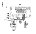
図1は、本実施形態で使用するインクジェット記録装置1(以下、記録装置1)の内部構成図である。図において、x方向は水平方向、y方向(紙面垂直方向)は後述する記録ヘッド8において吐出口が配列される方向、z方向は鉛直方向をそれぞれ示す。
<<
FIG. 1 is an internal configuration diagram of an inkjet recording device 1 (hereinafter, recording device 1) used in the present embodiment. In the figure, the x direction indicates the horizontal direction, the y direction (the direction perpendicular to the paper surface) indicates the direction in which the discharge ports are arranged in the
記録装置1は、プリント部2とスキャナ部3を備える複合機であり、記録動作と読取動作に関する様々な処理を、プリント部2とスキャナ部3で個別にあるいは連動して実行することができる。スキャナ部3は、ADF(オートドキュメントフィーダ)とFBS(フラットベッドスキャナ)を備えており、ADFで自動給紙される原稿の読み取りと、ユーザによってFBSの原稿台に置かれた原稿の読み取り(スキャン)を行うことができる。なお、本実施形態はプリント部2とスキャナ部3を併せ持った複合機であるが、スキャナ部3を備えない形態であってもよい。図1は、記録装置1が記録動作も読取動作も行っていない待機状態にあるときを示す。
The
プリント部2において、筐体4の鉛直方向下方の底部には、記録媒体(カットシート)Sを収容するための第1カセット5Aと第2カセット5Bが着脱可能に設置されている。第1カセット5AにはA4サイズまでの比較的小さな記録媒体が、第2カセット5BにはA3サイズまでの比較的大きな記録媒体が、平積みに収容されている。第1カセット5A近傍には、収容されている記録媒体を1枚ずつ分離して給送するための第1給送ユニット6Aが設けられている。同様に、第2カセット5B近傍には、第2給送ユニット6Bが設けられている。記録動作が行われる際にはいずれか一方のカセットから選択的に記録媒体Sが給送される。
In the
搬送ローラ7、排出ローラ12、ピンチローラ7a、拍車7b、ガイド18、インナーガイド19およびフラッパ11は、記録媒体Sを所定の方向に導くための搬送機構である。搬送ローラ7は、記録ヘッド8の上流側および下流側に配され、不図示の搬送モータによって駆動される駆動ローラである。ピンチローラ7aは、搬送ローラ7と共に記録媒体Sをニップして回転する従動ローラである。排出ローラ12は、搬送ローラ7の下流側に配され、不図示の搬送モータによって駆動される駆動ローラである。拍車7bは、記録ヘッド8の下流側に配される搬送ローラ7及び排出ローラ12と共に記録媒体Sを挟持して搬送する。
The
ガイド18は、記録媒体Sの搬送経路に設けられ、記録媒体Sを所定の方向に案内する。インナーガイド19は、y方向に延在する部材で湾曲した側面を有し、当該側面に沿って記録媒体Sを案内する。フラッパ11は、両面記録動作の際に、記録媒体Sが搬送される方向を切り替えるための部材である。排出トレイ13は、記録動作が完了し排出ローラ12によって排出された記録媒体Sを積載保持するためのトレイである。
The
本実施形態の記録ヘッド8は、フルラインタイプのカラーインクジェット記録ヘッドであり、記録データに従ってインクを吐出する吐出口が、図1におけるy方向に沿って記録媒体Sの幅に相当する分だけ複数配列されている。記録ヘッド8が待機位置にあるとき、記録ヘッド8の吐出口面8aは、図1のように鉛直下方を向きキャップユニット10によってキャップされている。記録動作を行う際は、後述するプリントコントローラ202によって、吐出口面8aがプラテン9と対向するように記録ヘッド8の向きが変更される。プラテン9は、y方向に延在する平板によって構成され、記録ヘッド8によって記録動作が行われる記録媒体Sを背面から支持する。記録ヘッド8の待機位置から記録位置への移動については、後に詳しく説明する。
The
インクタンクユニット14は、記録ヘッド8へ供給される4色のインクをそれぞれ貯留する。インク供給ユニット15は、インクタンクユニット14と記録ヘッド8を接続する流路の途中に設けられ、記録ヘッド8内のインクの圧力及び流量を適切な範囲に調整する。本実施形態では循環型のインク供給系を採用しており、インク供給ユニット15は記録ヘッド8へ供給されるインクの圧力と記録ヘッド8から回収されるインクの流量を適切な範囲に調整する。
The
メンテナンスユニット16は、キャップユニット10とワイピングユニット17を備え、所定のタイミングにこれらを作動させて、記録ヘッド8に対するメンテナンス動作を行う。メンテナンス動作については後に詳しく説明する。
The
図2は、記録装置1における制御構成を示すブロック図である。制御構成は、主にプリント部2を統括するプリントエンジンユニット200と、スキャナ部3を統括するスキャナエンジンユニット300と、記録装置1全体を統括するコントローラユニット100によって構成されている。プリントコントローラ202は、コントローラユニット100のメインコントローラ101の指示に従ってプリントエンジンユニット200の各種機構を制御する。スキャナエンジンユニット300の各種機構は、コントローラユニット100のメインコントローラ101によって制御される。以下に制御構成の詳細について説明する。
FIG. 2 is a block diagram showing a control configuration in the
コントローラユニット100において、CPUにより構成されるメインコントローラ101は、ROM107に記憶されているプログラムや各種パラメータに従って、RAM106をワークエリアとしながら記録装置1全体を制御する。例えば、ホストI/F102またはワイヤレスI/F103を介してホスト装置400から印刷ジョブが入力されると、メインコントローラ101の指示に従って、画像処理部108が受信した画像データに対して所定の画像処理を施す。そして、メインコントローラ101はプリントエンジンI/F105を介して、画像処理を施した画像データをプリントエンジンユニット200へ送信する。
In the
なお、記録装置1は無線通信や有線通信を介してホスト装置400から画像データを取得しても良いし、記録装置1に接続された外部記憶装置(USBメモリ等)から画像データを取得しても良い。無線通信や有線通信に利用される通信方式は限定されない。例えば、無線通信に利用される通信方式として、Wi−Fi(Wireless Fidelity)(登録商標)やBluetooth(登録商標)が適用可能である。また、有線通信に利用される通信方式としては、USB(Universal Serial Bus)等が適用可能である。また、例えばホスト装置400から読取コマンドが入力されると、メインコントローラ101は、スキャナエンジンI/F109を介してこのコマンドをスキャナ部3に送信する。
The
操作パネル104は、ユーザが記録装置1に対して入出力を行うための機構である。ユーザは、操作パネル104を介してコピーやスキャン等の動作を指示したり、印刷モードを設定したり、記録装置1の情報を認識したりすることができる。
The operation panel 104 is a mechanism for the user to input / output to / from the
プリントエンジンユニット200において、CPUにより構成されるプリントコントローラ202は、ROM203に記憶されているプログラムや各種パラメータに従って、RAM204をワークエリアとしながら、プリント部2が備える各種機構を制御する。コントローラI/F201を介して各種コマンドや画像データが受信されると、プリントコントローラ202は、これを一旦RAM204に保存する。記録ヘッド8が記録動作に利用できるように、プリントコントローラ202は画像処理コントローラ205に、保存した画像データを記録データへ変換させる。記録データが生成されると、プリントコントローラ202は、ヘッドI/F206を介して記録ヘッド8に記録データに基づく記録動作を実行させる。この際、プリントコントローラ202は、搬送制御部207を介して図1に示す給送ユニット6A、6B、搬送ローラ7、排出ローラ12、フラッパ11を駆動して、記録媒体Sを搬送する。プリントコントローラ202の指示に従って、記録媒体Sの搬送動作に連動して記録ヘッド8による記録動作が実行され、印刷処理が行われる。
In the
ヘッドキャリッジ制御部208は、記録装置1のメンテナンス状態や記録状態といった動作状態に応じて記録ヘッド8の向きや位置を変更する。インク供給制御部209は、記録ヘッド8へ供給されるインクの圧力が適切な範囲に収まるように、インク供給ユニット15を制御する。メンテナンス制御部210は、記録ヘッド8に対するメンテナンス動作を行う際に、メンテナンスユニット16におけるキャップユニット10やワイピングユニット17の動作を制御する。
The head
スキャナエンジンユニット300においては、メインコントローラ101が、ROM107に記憶されているプログラムや各種パラメータに従って、RAM106をワークエリアとしながら、スキャナコントローラ302のハードウェアリソースを制御する。これにより、スキャナ部3が備える各種機構は制御される。例えばコントローラI/F301を介してメインコントローラ101がスキャナコントローラ302内のハードウェアリソースを制御することにより、ユーザによってADFに搭載された原稿を、搬送制御部304を介して搬送し、センサ305によって読み取る。そして、スキャナコントローラ302は読み取った画像データをRAM303に保存する。なお、プリントコントローラ202は、上述のように取得された画像データを記録データに変換することで、記録ヘッド8に、スキャナコントローラ302で読み取った画像データに基づく記録動作を実行させることが可能である。
In the
図3は、記録装置1が記録状態にあるときを示す。図1に示した待機状態と比較すると、キャップユニット10が記録ヘッド8の吐出口面8aから離間し、吐出口面8aがプラテン9と対向している。本実施形態において、プラテン9の平面は水平方向に対して約45度傾いており、記録位置における記録ヘッド8の吐出口面8aも、プラテン9との距離が一定に維持されるように水平方向に対して約45度傾いている。
FIG. 3 shows when the
記録ヘッド8を図1に示す待機位置から図3に示す記録位置に移動する際、プリントコントローラ202は、メンテナンス制御部210を用いて、キャップユニット10を図3に示す退避位置まで降下させる。これにより、記録ヘッド8の吐出口面8aは、キャップ部材10aと離間する。その後、プリントコントローラ202は、ヘッドキャリッジ制御部208を用いて記録ヘッド8の鉛直方向の高さを調整しながら45度回転させ、吐出口面8aをプラテン9と対向させる。記録動作が完了し、記録ヘッド8が記録位置から待機位置に移動する際は、プリントコントローラ202によって上記と逆の工程が行われる。
When the
次に、プリント部2における記録媒体Sの搬送経路について説明する。記録コマンドが入力されると、プリントコントローラ202は、まず、メンテナンス制御部210およびヘッドキャリッジ制御部208を用いて、記録ヘッド8を図3に示す記録位置に移動する。その後、プリントコントローラ202は搬送制御部207を用い、記録コマンドに従って第1給送ユニット6Aおよび第2給送ユニット6Bのいずれかを駆動し、記録媒体Sを給送する。
Next, the transport path of the recording medium S in the
図4(a)〜(c)は、第1カセット5Aに収容されているA4サイズの記録媒体Sが給送されるときの搬送経路を示す図である。第1カセット5A内の1番上に積載された記録媒体Sは、第1給送ユニット6Aによって2枚目以降の記録媒体から分離され、搬送ローラ7とピンチローラ7aにニップされながら、プラテン9と記録ヘッド8の間の記録領域Pに向けて搬送される。図4(a)は、記録媒体Sの先端が記録領域Pに到達する直前の搬送状態を示す。記録媒体Sの進行方向は、第1給送ユニット6Aに給送されて記録領域Pに到達する間に、水平方向(x方向)から、水平方向に対して約45度傾いた方向に変更される。
4 (a) to 4 (c) are diagrams showing a transport path when the A4 size recording medium S housed in the
記録領域Pでは、記録ヘッド8に設けられた複数の吐出口から記録媒体Sに向けてインクが吐出される。インクが付与される領域の記録媒体Sは、プラテン9によってその背面が支持されており、吐出口面8aと記録媒体Sの距離が一定に保たれている。インクが付与された後の記録媒体Sは、搬送ローラ7と拍車7bに案内されながら、先端が右に傾いているフラッパ11の左側を通り、ガイド18に沿って記録装置1の鉛直方向上方へ搬送される。図4(b)は、記録媒体Sの先端が記録領域Pを通過して鉛直方向上方に搬送される状態を示す。記録媒体Sの進行方向は、水平方向に対し約45度傾いた記録領域Pの位置から、搬送ローラ7と拍車7bによって鉛直方向上方に変更されている。
In the recording area P, ink is ejected toward the recording medium S from a plurality of ejection ports provided in the
記録媒体Sは、鉛直方向上方に搬送された後、排出ローラ12と拍車7bによって排出トレイ13に排出される。図4(c)は、記録媒体Sの先端が排出ローラ12を通過して排出トレイ13に排出される状態を示す。排出された記録媒体Sは、記録ヘッド8によって画像が記録された面を下にした状態で、排出トレイ13上に保持される。
The recording medium S is conveyed upward in the vertical direction and then discharged to the
図5(a)〜(c)は、第2カセット5Bに収容されているA3サイズの記録媒体Sが給送されるときの搬送経路を示す図である。第2カセット5B内の1番上に積載された記録媒体Sは、第2給送ユニット6Bによって2枚目以降の記録媒体から分離され、搬送ローラ7とピンチローラ7aにニップされながら、プラテン9と記録ヘッド8の間の記録領域Pに向けて搬送される。
5 (a) to 5 (c) are diagrams showing a transport path when the A3 size recording medium S housed in the
図5(a)は、記録媒体Sの先端が記録領域Pに到達する直前の搬送状態を示す。第2給送ユニット6Bに給送されて記録領域Pに到達するまでの搬送経路には、複数の搬送ローラ7とピンチローラ7aおよびインナーガイド19が配されることで、記録媒体SはS字上に湾曲されてプラテン9まで搬送される。
FIG. 5A shows a transport state immediately before the tip of the recording medium S reaches the recording area P. A plurality of
その後の搬送経路は、図4(b)および(c)で示したA4サイズの記録媒体Sの場合と同様である。図5(b)は、記録媒体Sの先端が記録領域Pを通過して鉛直方向上方に搬送される状態を示す。図5(c)は、記録媒体Sの先端が排出ローラ12を通過して排出トレイ13に排出される状態を示す。
The subsequent transport path is the same as in the case of the A4 size recording medium S shown in FIGS. 4 (b) and 4 (c). FIG. 5B shows a state in which the tip of the recording medium S passes through the recording area P and is conveyed upward in the vertical direction. FIG. 5C shows a state in which the tip of the recording medium S passes through the
図6(a)〜(d)は、A4サイズの記録媒体Sの裏面(第2面)に対して記録動作(両面記録)を行う場合の搬送経路を示す。両面記録を行う場合、第1面(表面)を記録した後に第2面(裏面)に記録動作を行う。第1面を記録する際の搬送工程は図4(a)〜(c)と同様であるので、ここでは説明を省略する。以後、図4(c)以後の搬送工程について説明する。 6 (a) to 6 (d) show a transport path when a recording operation (double-sided recording) is performed on the back surface (second surface) of the A4 size recording medium S. When double-sided recording is performed, the recording operation is performed on the second surface (back surface) after recording the first surface (front surface). Since the transfer process for recording the first surface is the same as in FIGS. 4 (a) to 4 (c), the description thereof will be omitted here. Hereinafter, the transfer process after FIG. 4C will be described.
記録ヘッド8による第1面への記録動作が完了し、記録媒体Sの後端がフラッパ11を通過すると、プリントコントローラ202は、搬送ローラ7を逆回転させて記録媒体Sを記録装置1の内部へ搬送する。この際、フラッパ11は、不図示のアクチュエータによってその先端が左側に傾くように制御されるため、記録媒体Sの先端(第1面の記録動作における後端)はフラッパ11の右側を通過して鉛直方向下方へ搬送される。図6(a)は、記録媒体Sの先端(第1面の記録動作における後端)が、フラッパ11の右側を通過する状態を示す。
When the recording operation on the first surface by the
その後記録媒体Sは、インナーガイド19の湾曲した外周面に沿って搬送され、再び記録ヘッド8とプラテン9の間の記録領域Pに搬送される。この際、記録ヘッド8の吐出口面8aに、記録媒体Sの第2面が対向する。図6(b)は、第2面の記録動作のために、記録媒体Sの先端が記録領域Pに到達する直前の搬送状態を示す。
After that, the recording medium S is conveyed along the curved outer peripheral surface of the
その後の搬送経路は、図4(b)および(c)で示した第1面記録の場合と同様である。図6(c)は、記録媒体Sの先端が記録領域Pを通過して鉛直方向上方に搬送される状態を示す。この際、フラッパ11は、不図示のアクチュエータにより先端が右側に傾いた位置に移動するように制御される。図6(d)は、記録媒体Sの先端が排出ローラ12を通過して排出トレイ13に排出される状態を示す。
The subsequent transport route is the same as in the case of the first surface recording shown in FIGS. 4 (b) and 4 (c). FIG. 6C shows a state in which the tip of the recording medium S passes through the recording area P and is conveyed upward in the vertical direction. At this time, the
<メンテナンス動作>
次に、記録ヘッド8に対するメンテナンス動作について説明する。図1でも説明したように、本実施形態のメンテナンスユニット16は、キャップユニット10とワイピングユニット17とを備え、所定のタイミングにこれらを作動させてメンテナンス動作を行う。
<Maintenance operation>
Next, the maintenance operation for the
図7は、記録装置1がメンテナンス状態のときの図である。記録ヘッド8を図1に示す待機位置から図7に示すメンテナンス位置に移動する際、プリントコントローラ202は、記録ヘッド8を鉛直方向において上方に移動させるとともにキャップユニット10を鉛直方向下方に移動させる。そして、プリントコントローラ202は、ワイピングユニット17を退避位置から図7における右方向に移動させる。その後、プリントコントローラ202は、記録ヘッド8を鉛直方向下方に移動させメンテナンス動作が可能なメンテナンス位置に移動させる。
FIG. 7 is a diagram when the
一方、記録ヘッド8を図3に示す記録位置から図7に示すメンテナンス位置に移動する際、プリントコントローラ202は、記録ヘッド8を45度回転させつつ鉛直方向上方に移動させる。そして、プリントコントローラ202は、ワイピングユニット17を退避位置から右方向に移動させる。その後プリントコントローラ202は、記録ヘッド8を鉛直方向下方に移動させて、メンテナンスユニット16によるメンテナンス動作が可能なメンテナンス位置に移動させる。
On the other hand, when the
図8(a)はメンテナンスユニット16が待機ポジションにある状態を示す斜視図であり、図8(b)はメンテナンスユニット16がメンテナンスポジションにある状態を示す斜視図である。図8(a)は図1に対応し、図8(b)は図7に対応している。記録ヘッド8が待機位置にあるとき、メンテナンスユニット16は図8(a)に示す待機ポジションにあり、キャップユニット10は鉛直方向上方に移動しており、ワイピングユニット17はメンテナンスユニット16の内部に収納されている。キャップユニット10はy方向に延在する箱形のキャップ部材10aを有し、これを記録ヘッド8の吐出口面8aに密着させることにより、吐出口からのインクの蒸発を抑制することができる。また、キャップユニット10は、キャップ部材10aに予備吐出等で吐出されたインクを回収し、回収したインクを不図示の吸引ポンプに吸引させる機能も備えている。
FIG. 8A is a perspective view showing a state in which the
一方、図8(b)に示すメンテナンスポジションにおいて、キャップユニット10は鉛直方向下方に移動しており、ワイピングユニット17がメンテナンスユニット16から引き出されている。ワイピングユニット17は、ブレードワイパユニット171とバキュームワイパユニット172の2つのワイパユニット(ワイピング部材)を備えている。
On the other hand, in the maintenance position shown in FIG. 8B, the
ブレードワイパユニット171には、吐出口面8aをx方向に沿ってワイピングするためのブレードワイパ171aが吐出口の配列領域に相当する長さだけy方向に配されている。ブレードワイパユニット171を用いてワイピング動作を行う際、ワイピングユニット17は、記録ヘッド8がブレードワイパ171aに当接可能な高さに位置決めされた状態で、ブレードワイパユニット171をx方向に移動する。この移動により、吐出口面8aに付着するインクなどはブレードワイパ171aに拭き取られる。
In the
ブレードワイパ171aが収納される際のメンテナンスユニット16の入り口には、ブレードワイパ171aに付着したインクを除去するとともにブレードワイパ171aにウェット液を付与するためのウェットワイパクリーナ16aが配されている。ブレードワイパ171aは、メンテナンスユニット16に収納される度にウェットワイパクリーナ16aによって付着物が除去されウェット液が塗布される。そして、次に吐出口面8aをワイピングしたときにウェット液を吐出口面8aに転写し、吐出口面8aとブレードワイパ171a間の滑り性を向上させている。
At the entrance of the
一方、バキュームワイパユニット172は、y方向に延在する開口部を有する平板172aと、開口部内をy方向に移動可能なキャリッジ172bと、キャリッジ172bに搭載されたバキュームワイパ172cとを有する。バキュームワイパ172cは、キャリッジ172bの移動に伴って吐出口面8aをy方向にワイピング可能に配されている。バキュームワイパ172cの先端には、不図示の吸引ポンプに接続された吸引口が形成されている。このため、吸引ポンプを作動させながらキャリッジ172bをy方向に移動すると、記録ヘッド8の吐出口面8aに付着したインク等は、バキュームワイパ172cによって拭き寄せられながら吸引口に吸い込まれる。この際、平板172aと開口部の両端に設けられた位置決めピン172dは、バキュームワイパ172cに対する吐出口面8aの位置合わせに利用される。
On the other hand, the
本実施形態では、ブレードワイパユニット171によるワイピング動作を行いバキュームワイパユニット172によるワイピング動作を行わない第1のワイピング処理と、両方のワイピング処理を順番に行う第2のワイピング処理を実施することができる。第1のワイピング処理を行う際、プリントコントローラ202は、まず、記録ヘッド8を図7のメンテナンス位置よりも鉛直方向上方に退避させた状態で、ワイピングユニット17をメンテナンスユニット16から引き出す。そして、プリントコントローラ202は、記録ヘッド8をブレードワイパ171aに当接可能な位置まで鉛直方向下方に移動させた後、ワイピングユニット17をメンテナンスユニット16内へ移動させる。この移動により、吐出口面8aに付着するインク等はブレードワイパ171aに拭き取られる。すなわち、ブレードワイパ171aは、メンテナンスユニット16から引き出された位置からメンテナンスユニット16内へ移動する際に吐出口面8aをワイピングする。
In the present embodiment, it is possible to carry out a first wiping process in which the wiping operation by the
ブレードワイパユニット171が収納されると、プリントコントローラ202は、次にキャップユニット10を鉛直方向上方に移動させ、キャップ部材10aを記録ヘッド8の吐出口面8aに密着させる。そして、プリントコントローラ202は、その状態で記録ヘッド8を駆動して予備吐出を行わせ、キャップ部材10a内に回収されたインクを吸引ポンプによって吸引する。
When the
一方、第2のワイピング処理を行う際、プリントコントローラ202は、まず、記録ヘッド8を図7のメンテナンス位置よりも鉛直方向上方に退避させた状態で、ワイピングユニット17をメンテナンスユニット16からスライドさせて引き出す。そして、プリントコントローラ202は、記録ヘッド8をブレードワイパ171aに当接可能な位置まで鉛直方向下方に移動させた後、ワイピングユニット17をメンテナンスユニット16内へ移動させる。これにより、ブレードワイパ171aによるワイピング動作が吐出口面8aに対して行われる。次に、プリントコントローラ202は、再び記録ヘッド8を図7のメンテナンス位置よりも鉛直方向上方に退避させた状態で、ワイピングユニット17をメンテナンスユニット16からスライドさせて所定位置まで引き出す。続いて、プリントコントローラ202は、記録ヘッド8を図7に示すワイピング位置に下降させながら、平板172aと位置決めピン172dを用いて吐出口面8aとバキュームワイパユニット172の位置決めを行う。その後、プリントコントローラ202は、上述したバキュームワイパユニット172によるワイピング動作を実行する。プリントコントローラ202は、記録ヘッド8を鉛直方向上方に退避させ、ワイピングユニット17を収納した後、第1のワイピング処理と同様に、キャップユニット10によるキャップ部材内への予備吐出と回収したインクの吸引動作を行う。
On the other hand, when performing the second wiping process, the
<記録ヘッドとキャップユニットとの複数の相対位置が求められる理由>
次に、記録ヘッド8とキャップユニット10との相対的な位置(相対位置)を複数規定することが求められている理由を説明する。複数の相対位置を規定することで以下のような様々なメンテナンスの態様が可能になる。
<Reason why multiple relative positions of the recording head and cap unit are required>
Next, the reason why it is required to specify a plurality of relative positions (relative positions) between the
第1の態様として、第1の相対位置において第1のインクの予備吐出を行い、第2の相対位置において第1のインクとは異なる種類の第2のインクの予備吐出を行う態様が挙げられる。予備吐出とは、所定時間未使用であった吐出口のインクの乾燥や混色を防止するために、記録とは無関係な位置(例えば、キャップ部材10a上の位置)で排出するための動作である。前述したように、記録ヘッド8の吐出口面8aは、キャップユニット10のキャップ部材10aに密着してキャッピングが行われ、その状態で記録ヘッドが駆動されて予備吐出が行われる。
As a first aspect, a mode in which the first ink is pre-discharged at the first relative position and the second ink of a type different from the first ink is pre-discharged at the second relative position can be mentioned. .. Preliminary ejection is an operation for ejecting ink at a position unrelated to recording (for example, a position on the
インクの中には、他のインクよりも増粘しやすいインク(例えば顔料を多く含むブラックのインク)がある。記録ヘッド8とキャップユニット10との相対位置が固定的な状態(一義的に位置決めされた状態)で予備吐出を行うと、キャップ部材10a上で予備吐出されるインクの位置関係は、吐出口列の配列と同じ位置関係となる。つまり、増粘しやすいインクは、キャップ部材10a上において同一の位置に対して吐出され続ける。この結果、増粘しやすいインクがキャップ部材10a上において堆積してしまう場合がある。そこで、予備吐出したインクがキャップ部材10a上に堆積してしまうことを抑制するために、増粘しにくいカラーインクが着弾しているキャップ部材10aの上の領域に、増粘しやすいブラックインクを予備吐出したいというニーズがある。また逆に、増粘しやすいブラックインクを予備吐出した領域に、カラーインクが重なるように予備吐出したい、というニーズもある。なお、予備吐出によってインクが着弾する場所は「位置」と称し、キャップ部材10a上に着弾済みのインクの場所を「領域」と称する。これは、着弾したインクが吸収体115(図18参照)上で広がって領域を形成する場合があるためである。
Some inks are more viscous than other inks (for example, black inks containing a large amount of pigment). When the preliminary ejection is performed in a state where the relative positions of the
本実施形態において記録ヘッド8は、フルラインタイプのカラーインクジェット記録ヘッドであり、吐出口列は記録媒体Sの幅に相当する分だけ延在して配列されている。各インクの各吐出口列は、吐出口列が延在する方向と交差する第1の方向(X方向)に並んでいる。キャップ部材10aは、これらの吐出口列を覆うようにY方向に延在した部材となっている。予備吐出されるブラックインクが着弾する位置を、キャップ部材10a上でカラーインクが着弾している領域に重ねようとすると、記録ヘッド8とキャップ部材10aとの相対位置を第1の方向(X方向)において複数規定する必要がある。すなわち、記録ヘッド8とキャップユニット10とを、第1の方向において異なる位置に位置決めすることが求められる。
In the present embodiment, the
第2の態様として、キャッピングをする位置と予備吐出を行う位置とを異ならせる態様が挙げられる。例えば、第1の相対位置でキャッピングをして吸引を行い、第2の相対位置で特定の色の予備吐出を行う態様がある。 As a second aspect, there is an aspect in which the capping position and the preliminary discharge position are different from each other. For example, there is an embodiment in which capping is performed at the first relative position to perform suction, and pre-discharge of a specific color is performed at the second relative position.
第3の態様として、複数の位置でキャッピングする態様が挙げられる。例えば、キャップユニット10がキャッピングの位置に移動する際の記録ヘッド8の位置に応じてキャッピング位置を異ならせる態様がある。すなわち、複数箇所のキャッピング位置を有する場合は移動距離が短い方のキャッピング位置に移動する態様がある。あるいは、キャッピング状態を維持している待機状態の場合のキャッピング位置と、吸引動作を行う際のキャッピング位置とを異ならせる態様もある。
As a third aspect, there is an aspect of capping at a plurality of positions. For example, there is an embodiment in which the capping position is changed according to the position of the
以下の実施形態では、上述した第1の態様、すなわち、予備吐出を行う位置を異ならせる形態を例に挙げて、記録ヘッド8とキャップユニット10との複数の相対位置を規定する形態を説明する。
In the following embodiment, the first aspect described above, that is, the embodiment in which the pre-discharge position is different, will be taken as an example to explain the embodiment in which a plurality of relative positions of the
<記録ヘッドとキャップユニットとの位置決め>
記録ヘッド8とキャップユニット10との相対的な位置を決める位置決め部の構成を説明する。
<Positioning of recording head and cap unit>
The configuration of the positioning unit that determines the relative positions of the
図9は、記録ヘッド8とキャップユニット10との相対的な位置を決める位置決め部を説明する図である。図9(a)は、記録ヘッド8の吐出口面8aを含む部分的な斜視図である。図9(b)は、キャップユニット10の斜視図である。
FIG. 9 is a diagram illustrating a positioning unit that determines a relative position between the
図9(a)に示すように、記録ヘッド8の長手方向(Y方向)の両端部には、位置決め部として用いられる位置決め部材8bが備えられている。本実施形態では、位置決め部材8bの第1の方向(X方向)に形成されている面が、記録ヘッド8の位置決め面として用いられる。
As shown in FIG. 9A, positioning
図9(b)に示すキャップユニット10は、キャップホルダ110を備えており、キャップホルダ110には、キャップ部材10aが備えられている。また、キャップホルダ110において、キャップ部材10aの長手方向(Y方向)の両端部には、位置決め部として用いられる第1の位置決め部材10bと第2の位置決め部材10cとがそれぞれ備えられている。図9(b)に示すように、第1の位置決め部材10bは、キャップユニット10のX方向において、キャップユニット10が退避する側(図1の左側)に備えられている。第2の位置決め部材10cは、キャップユニット10のX方向において、第1の位置決め部材10bと対向する位置に設けられている。すなわち、第2の位置決め部材10cは図1における右側に備えられている。本実施形態では、第1の位置決め部材10bは、固定部材であり、第2の位置決め部材10cは、可動部材である。
The
第1の位置決め部材10bと第2の位置決め部材10cとの間の第1の方向(X方向)の長さは、記録ヘッド8の位置決め部材8bの第1の方向(X方向)の長さよりも長い。このため、記録ヘッド8の位置決め部材8bが、第1の位置決め部材10bと第2の位置決め部材10cとの間に入り込むことができる。そして、キャップユニット10(キャップ部材10a)の第1の方向(X方向)の移動を制御することで、複数の相対的な位置の位置決めを行うことができる。すなわち、記録ヘッド8の位置決め部材8bの第1の位置決め面81と、キャップユニット10の第1の位置決め部材10bとが当接する第1の相対位置を位置決めできる。また、記録ヘッド8の位置決め部材8bの第2の位置決め面82(第1の位置決め面81とは反対側の面)と、キャップユニット10の第2の位置決め部材10cとが当接する第2の相対位置を位置決めできる。このように、本実施形態では、キャップホルダ110のY方向の両端に設けられた第1の位置決め部材10bおよび第2の位置決め部材10cと、記録ヘッド8のY方向の両端に設けられた位置決め部材8bとを用いて位置決めがされる。
The length in the first direction (X direction) between the
<キャップユニットの移動について>
図10は、キャップユニット10を説明する図である。図10を用いて、キャップユニット10が水平状態を保ったまま、図3に示す退避位置から図1に示すキャッピング位置へ移動する例を説明する。
<About moving the cap unit>
FIG. 10 is a diagram illustrating the
図10(a)は、キャップユニット10が図1に示すキャッピング位置に移動した図である。図10(b)は、キャップユニット10が図3に示す退避位置に移動した図である。図10(c)は、キャップユニット10のギア列の例を示す図である。図10(d)は、図10(a)の矢印A方向から見たキャップユニット10の部分拡大図である。
FIG. 10A is a diagram in which the
図10(a)および図10(c)に示すように、キャップユニット10は、セクタギア501、第1ギア502、第2ギア503、およびキャップホルダギア504を含むギア列を備えている。ギア列は、装置の前面側(図10の手前側)と背面側(図10の奥側)とに対称的に備えられており、駆動モータ505によって前面側のギア列と背面側のギア列とが同時に駆動される。
As shown in FIGS. 10 (a) and 10 (c), the
本実施形態では、セクタギア501と第1ギア502のギア中心が同一である。また、セクタギア501はベース部材507に回転可能に保持され、第1ギア502はベース部材507に回転不能に固定されている。キャップホルダギア504と第2ギア503とは、セクタギア501に回転可能に保持されており、第2ギア503は第1ギア502およびキャップホルダギア504の双方に連結されている。また、第1ギア502とキャップホルダギア504とのギアの緒元(歯数)は同じである。
In this embodiment, the gear centers of the
このような構成でセクタギア501を回動させると、第1ギア502は回転しないため、第1ギア502に噛み合う第2ギア503が第1ギア502の周りを自転しながら、セクタギア501と共に公転することとなる。ここで第1ギア502とキャップホルダギア504との諸元(歯数)が同じなので、両者の回転数は等しい。これにより、セクタギア501が回転した角度と同じだけキャップホルダギア504が逆方向に回転し、キャップホルダギア504の姿勢は、セクタギア501の角度に関係なく一定となる。キャップホルダ110が水平のまま移動できる構成となっている。
When the
なお、ギアで回転させると、バックラッシュやキャップホルダ110の重量などの影響で、キャップホルダギア504の自由端側が垂れ下がり、傾きやすくなる。そこで、キャップユニット10の姿勢保持のために、図10(d)のバネ506(付勢部材)で重力方向の上方に付勢し、自由端側を釣り上げている。キャッピングの際には、記録ヘッド8によってキャップホルダ110がメンテナンスユニット16のベース部材(不図示)に押し付けられて、姿勢が固定される。
When rotated by a gear, the free end side of the
駆動モータ505は、メンテナンス制御部210の制御によって駆動量が制御され、メンテナンス制御部210は、プリントコントローラ202からの指示に応じて駆動量の制御を行う。
The drive amount of the
<移動シーケンスの概要>
次に、記録ヘッド8とキャップユニット10とが移動する移動シーケンスの概要を説明する。図11、図12、および図13は、キャップユニット10が移動する概要を説明する図である。これらの図は、図1などと同様に、装置の前面側から見た模式図であり、関連する部分を抜粋して示している。また、部分的にギアを透過的に示している。
<Overview of movement sequence>
Next, the outline of the movement sequence in which the
図11(a)は、図3に示す退避位置からセクタギアが回動し、キャップホルダ110が少し上昇している図である。水平方向に対して約45度傾いていた記録ヘッド8(図では、記録ヘッドの位置決め部材8bを示す。図12および図13においても同様)は、吐出口面8aを鉛直方向の下方に向けた姿勢となっている。図11(b)は、図11(a)の状態の後、セクタギア501が図11における時計回りに回動することでキャップホルダ110が記録ヘッド8の鉛直方向の下方に位置していることを示す図である。図11(c)は、図11(b)の状態の後に、さらにセクタギア501が回動して、キャップ準備位置に到達したことを示す図である。キャップ準備位置とは、記録ヘッド8が降下を開始する際のキャップユニット10の位置である。
FIG. 11A is a diagram in which the sector gear rotates from the retracted position shown in FIG. 3 and the
図12(a)は、キャップユニット10がキャップ準備位置に達した後に、記録ヘッド8が降下したことを示す図である。すなわち、図12(a)は、図11(c)の状態の後に、プリントコントローラ202からの指示に応じてヘッドキャリッジ制御部208が記録ヘッド8を降下させた状態の図である。図12(b)は、記録ヘッド8が降下した後に、セクタギア501をさらに回動して、位置決め部材8bの第1の位置決め面81と、キャップホルダ110の第1の位置決め部材10bとを当接させた状態の図である。すなわち、図12(b)は、記録ヘッド8の位置決め部材8bの第1の位置決め面81と、キャップホルダ110の第1の位置決め部材10bとが当接して第1の相対位置になっている。図12(c)は、図12(b)の後に記録ヘッド8が降下し、キャップ部材10aに記録ヘッド8が押し当てられた状態、すなわち、キャッピングが行われる状態を示す図である。図12(c)の状態を第1の相対位置としてもよい。
FIG. 12A is a diagram showing that the
図13(a)は、図12(c)の状態の後に、記録ヘッド8を上昇させた図である。図13(b)は、これまでとは反対側(図13における反時計回り)にセクタギア501を回動させて、位置決め部材8bの第2の位置決め面82と、キャップホルダ110の第2の位置決め部材10cとを水平方向に当接させた状態の図である。すなわち、図13(b)は、記録ヘッド8の位置決め部材8bの第2の位置決め面82と、キャップホルダ110の第2の位置決め部材10cとが当接して第2の相対位置になっている。以上が移動シーケンスの概要である。
FIG. 13 (a) is a diagram in which the
<第1の相対位置への移動制御>
次に、記録ヘッド8とキャップユニット10とが第1の相対位置に移動する移動シーケンスの詳細を説明する。
<Movement control to the first relative position>
Next, the details of the movement sequence in which the
図14は、キャップユニット10が、図11(c)のキャップ準備位置に位置した状態の部分的な斜視図である。図14は、図11(c)の矢印Cの方向から見た図である。以降では、主に断面位置Aの断面図と断面位置Bの断面図とを用いて移動制御を説明する。なお、断面位置Aは、位置決め部材8b、位置決め部材10b、10cを含む断面である。断面位置Bは、断面位置Aよりも記録ヘッド8(またはキャップユニット10)の長手方向における中央側の断面であり、位置決め部材8b、位置決め部材10b、10cを含まず、吐出口を含む断面である。
FIG. 14 is a partial perspective view showing a state in which the
図15(a)は、図11(c)のキャップ準備位置におけるキャップホルダ110付近の拡大図である。メンテナンス制御部210は、キャップユニット10がキャップ準備位置に到達すると、駆動モータ505を停止して、セクタギア501の回動を停止する。これにより、キャップユニット10の移動が停止する。図15(b)は、図15(a)のキャップ準備位置における断面位置Aにおける断面を示す図である。位置決め部材8bの第1の位置決め面81と、キャップホルダ110の第1の位置決め部材10bとの間には、距離d1の隙間が設けられている。この隙間は、記録ヘッド8が降下した場合に、記録ヘッドの位置決め部材8bが、第1の位置決め部材10bと接触しないようにするために設けられている。また、このときの記録ヘッド8の位置決め部材8bは、キャップホルダ110の第2の位置決め部材10c(可動部材)の鉛直方向の上方に位置する。第2の位置決め部材10cは、バネ111が設けられており、鉛直方向に移動可能に構成されている可動部材である。このため、記録ヘッド8が降下して位置決め部材8bが第2の位置決め部材10cに突き当たると、第2の位置決め部材10cは、記録ヘッド8の降下に応じて鉛直方向の下方に移動して、退避する。
FIG. 15A is an enlarged view of the vicinity of the
このように第2の位置決め部材10cを可動部材として構成している理由は、第1の相対位置と第2の相対位置との間の移動量(ずらし量)が少ないケースを考慮しているからである。例えば、第1の相対位置と第2の相対位置との間の移動量が3mmの場合を想定する。ここで、仮に第2の位置決め部材10cを固定部材とした場合には、キャップ準備位置でのキャップユニット10の停止精度によっては、記録ヘッド8を降下した場合に第2の位置決め部材10cに衝突してしまう場合がある。第2の位置決め部材10cを可動部材にすることで、位置決め部材10cは、記録ヘッド8の降下に応じて退避できるので、記録ヘッド8と第2の位置決め部材10cとの衝突を防止できる。
The reason why the
図16は、図12(a)の状態の断面位置Aにおける断面を示す図である。すなわち、キャップユニット10がキャップ準備位置に達した後に、プリントコントローラ202からの指示に応じてヘッドキャリッジ制御部208が記録ヘッド8を降下させた状態の図である。記録ヘッド8の降下によって、位置決め部材8bと、キャップホルダ110の第2の位置決め部材10cとが、鉛直方向において当接する。また、記録ヘッド8の降下に応じて、キャップホルダ110の第2の位置決め部材10cが鉛直方向に押し込まれている。
FIG. 16 is a diagram showing a cross section at the cross section position A in the state of FIG. 12 (a). That is, after the
図17は、図12(b)の状態の断面位置Aにおける断面を示す図である。すなわち、記録ヘッド8が降下した後に、セクタギア501をさらに回動して、記録ヘッドの位置決め部材8bと、キャップホルダ110の第1の位置決め部材10bとを当接させた状態の図である。図17に示すように、セクタギア501の回動に応じてキャップホルダ110の位置が、図17の矢印E方向に移動する。このため、距離d2に示すように、記録ヘッド8の位置決め部材8bとキャップホルダ110の第2の位置決め部材10c(可動部材)とが離間し、隙間が生じる。このため、押し込まれていたバネが復元され、第2の位置決め部材10cが、押し込まれる前の状態に戻る。図17では、記録ヘッド8の位置決め部材8bの第1の位置決め面81と、キャップユニット10の第1の位置決め部材10bとが当接する第1の相対位置となっている。
FIG. 17 is a diagram showing a cross section at the cross section position A in the state of FIG. 12 (b). That is, after the
図18(a)は、図12(c)の状態の断面位置Aにおける断面を示す図であり、図18(b)は、図12(c)の状態の断面位置Bにおける断面を示す図である。すなわち図18は、記録ヘッド8が降下してキャッピングが行われる状態を示す図である。図18(a)に示すように、記録ヘッド8が降下することにより、吐出口面8aとキャップ部材10aとが当接し、キャップホルダ110も所定の位置まで押し下げられる。図18(b)に示すように、キャップホルダ110の下部には、キャップホルダ110を所定圧で記録ヘッド8の吐出口面8aに押し当てるキャップバネ112が設けられている。このキャップバネ112の反力で、キャップホルダ110がメンテナンスユニット16のベース部材に当接する。
FIG. 18 (a) is a diagram showing a cross section at the cross-sectional position A in the state of FIG. 12 (c), and FIG. 18 (b) is a diagram showing a cross section at the cross-sectional position B in the state of FIG. 12 (c). be. That is, FIG. 18 is a diagram showing a state in which the
この図18における記録ヘッド8とキャップユニット10との第1の方向(X方向)における相対的な位置は、図17の位置と同じである。よって、図18もまた、記録ヘッド8とキャップユニット10とが第1の相対位置にある状態を示す図である。この状態において、プリントコントローラ202は、図18(b)に示すように、記録ヘッド8にカラーインクの予備吐出を行わせる。記録ヘッド8の吐出口面8aには、吐出口80a、80b、80c、80dが備えられており、それぞれイエロー、マゼンタ、シアン、ブラックの各インクの吐出口列に対応する。第1の相対位置においては、ブラックインク以外のカラーインクの吐出口80a〜80cから予備吐出が行われる。予備吐出されたインクは、キャップ吸収体115に吸収される。
The relative positions of the
<第2の相対位置への移動制御>
次に、記録ヘッド8とキャップユニット10とが第1の相対位置から第2の相対位置になるように移動する移動制御を説明する。
<Movement control to the second relative position>
Next, the movement control in which the
図19は、図13(a)の状態の断面位置Aにおける断面を示す図である。すなわち、図19は、図18の状態の後に、記録ヘッド8を上昇させた図である。図19では、記録ヘッドの吐出口面8aがキャップ部材10aから離間している。
FIG. 19 is a diagram showing a cross section at the cross section position A in the state of FIG. 13 (a). That is, FIG. 19 is a diagram in which the
図20(a)は、図13(b)の状態の断面位置Aにおける断面を示す図であり、図20(b)は、図13(b)の状態の断面位置Bにおける断面を示す図である。すなわち、図20は、これまでとは反対側にセクタギアを回動させて記録ヘッドの位置決め部材8bと、キャップホルダ110の第2の位置決め部材10cとを水平方向に当接させた状態の図である。図20(a)に示すように、記録ヘッド8の位置決め部材8bの第2の位置決め面82と、キャップユニット10の第2の位置決め部材10cとが水平方向で当接する第2の相対位置が位置決めされる。図20(b)に示すように、この第2の相対位置においてブラックの吐出口80dから予備吐出を行うと、カラーインクの予備吐出が着弾している領域にブラックインクが重なるように着弾する。
20 (a) is a diagram showing a cross section at the cross-sectional position A in the state of FIG. 13 (b), and FIG. 20 (b) is a diagram showing a cross section at the cross-sectional position B in the state of FIG. 13 (b). be. That is, FIG. 20 is a view showing a state in which the sector gear is rotated to the opposite side to the previous one so that the
なお、図20の例では、記録ヘッド8の吐出口面8aと、キャップ部材10aとが離間している状態で予備吐出を行う場合を例に挙げて説明したが、これに限られるものではない。記録ヘッド8がさらに降下して吐出口面8aと、キャップ部材10aとが当接してキャッピングされた状態で予備吐出が行われてもよい。つまり、記録ヘッド8がキャッピングされた状態についても第2の相対位置に位置決めされた状態であるとしてもよい。なお、前述の図18で説明した、カラーインクが予備吐出される場合も、キャッピング状態でなくてもよく、記録ヘッド8の吐出口面8aとキャップ部材10aとが離間している状態で予備吐出が行われてもよい。
In the example of FIG. 20, the case where the preliminary discharge is performed in a state where the
以上説明したように、本実施形態によれば、記録ヘッド8とキャップユニット10とを、吐出口列と交差する第1の方向(X方向)において異なる位置に位置決めすることできる。このため、記録ヘッド8とキャップユニット10との相対的な位置を複数規定したいというニーズに応えることが可能となる。
As described above, according to the present embodiment, the
なお、上述した実施形態では、キャップユニット10の第1の位置決め部材10bを固定部材とし、第2の位置決め部材10cを可動部材とする形態を例に挙げて説明したが、これに限られるものではない。第1の位置決め部材10bを可動部材とし、第2の位置決め部材10cを固定部材としてもよい。また、第1の位置決め部材10bおよび第2の位置決め部材10cを可動部材としてもよい。また、第1の相対位置と第2の相対位置との間の移動量(ずらし量)が、記録ヘッド8やキャップユニット10の移動精度を考慮しなくて済む程度に大きい場合には、第1の位置決め部材10bおよび第2の位置決め部材10cを固定部材としてもよい。
In the above-described embodiment, the
また、上述した実施形態では、記録ヘッド8の位置決め部材8bと、キャップユニット10の位置決め部材10b、10cが、長手方向の両端に対称的に備えられている形態を例に挙げて説明した。すなわち、2つの位置決め部材8bのサイズは同じ大きさであり、対向する位置決め部材10bと位置決め部材10cとの間の長さはそれぞれ同じ大きさである例を説明した。しかしながら、記録ヘッド8やキャップユニット10の長手方向の一端の形状やサイズが、他端の形状やサイズと異なっていても良い。この場合、各端において、第1の相対位置および第2の相対位置に位置決めする際の移動量に応じて適したサイズや形状の位置決め部材8b、10b、10cを適宜採用すればよい。
Further, in the above-described embodiment, the configuration in which the
<<実施形態2>>
実施形態1では、第1の相対位置では、記録ヘッド8の第1の位置決め部(第1の位置決め面81)に対して、キャップユニット10の第2の位置決め部(第1の位置決め部材10b)が当接する形態を説明した。また、第2の相対位置では、記録ヘッド8の第3の位置決め部(第2の位置決め面82)に対して、キャップユニット10の第4の位置決め部(第2の位置決め部材10c)が当接する形態を説明した。つまり、それぞれの相対位置で当接する部位が、記録ヘッド8もキャップユニット10もどちらも異なる部位である形態を説明した。
<<
In the first embodiment, in the first relative position, the second positioning portion (first positioning
本実施形態では、記録ヘッド8の1箇所の位置決め部に対して、キャップユニット10の異なる部位の位置決め部によって、複数の相対位置を位置決めする形態を説明する。
In the present embodiment, a mode will be described in which a plurality of relative positions are positioned with respect to one positioning portion of the
図21は、実施形態1で説明した例と同様に、図14の断面位置Aにおける断面を示す図である。本実施形態では、キャップホルダ110が、実施形態1とは異なっている。本実施形態のキャップホルダ110は、X方向の一端側の位置決め部材10hが、複数の段差形状で構成されている。すなわち、位置決め部材10hのX方向における厚さがキャップホルダ110の下部に向けて段階的に大きくなるように構成されている。また、各段差の間には、斜面が形成されている。本実施形態では、図21に示すように、キャップホルダ110の位置決め部材10hは、第1の位置決め面10d、第2の位置決め面10e、第1の斜面10fおよび第2の斜面10gが形成されている。また、キャップユニット10は、キャップホルダバネ113を備えており、キャップホルダバネ113によってキャップユニット10(キャップホルダ110を含む)は、図21の矢印E方向に付勢されている(左寄せ)。図21は、本実施形態のキャップ準備位置を示す図である。本実施形態のキャップ準備位置は、第1の斜面10fの鉛直方向の上方に記録ヘッド8の位置決め部8bの角部が対向する位置である。
FIG. 21 is a diagram showing a cross section at the cross-sectional position A of FIG. 14, similar to the example described in the first embodiment. In this embodiment, the
図22は、図21と同様に、断面位置Aにおける断面を示す図である。図22(a)は、本実施形態の第1の相対位置を示す図であり、図22(b)は、本実施形態の第2の相対位置を示す図である。図21に示す状態から、記録ヘッド8が下降する。記録ヘッド8が下降する際に位置決め部材8bは、第1の斜面10f、第2の位置決め面10e、第2の斜面10g、第1の位置決め面10dの順に当接する。このとき、第1の斜面10fおよび第2の斜面10gによって、キャップホルダ110が図22(a)の矢印F方向(右方向)に寄せられる。記録ヘッド8の吐出口面8aがキャップ部材10aと当接する位置まで記録ヘッド8が降下することで、記録ヘッド8の位置決め部材8bの位置決め面が、キャップホルダ110の第1の位置決め面10dと当接する。これにより、記録ヘッド8とキャップユニット10とは第1の相対位置となる。
FIG. 22 is a diagram showing a cross section at the cross section position A, similarly to FIG. 21. FIG. 22A is a diagram showing a first relative position of the present embodiment, and FIG. 22B is a diagram showing a second relative position of the present embodiment. The
図22(b)は、図22(a)に示す状態から、記録ヘッド8を上昇させた図である。記録ヘッド8を上昇させると、位置決め部材8bの位置決め面が、第1の位置決め面10dから離間する。ヘッドキャリッジ制御部208は、キャップホルダ110の第2の位置決め面10eと位置決め部材8bの位置決め面とが当接可能な位置で記録ヘッド8の上昇を停止させる。キャップホルダ110は、キャップホルダバネ113により図22(b)の矢印E方向に付勢されているので、第2の位置決め面10eが、記録ヘッドの位置決め部材8bの位置決め面と当接する。これにより、記録ヘッド8とキャップユニット10とは第2の相対位置となる。
FIG. 22B is a view in which the
以上説明したように、本実施形態では、記録ヘッド8の1箇所の位置決め部に対して、キャップユニット10の異なる部位の位置決め部によって、複数の相対位置を位置決めすることが可能である。
As described above, in the present embodiment, it is possible to position a plurality of relative positions with respect to one positioning portion of the
<<実施形態3>>
本実施形態では、キャップユニット10の1箇所の位置決め部に対して、記録ヘッド8の異なる部位の位置決め部のそれぞれによって、複数の相対位置を位置決めすることが可能な形態を説明する。
<<
In the present embodiment, a mode in which a plurality of relative positions can be positioned with respect to one positioning portion of the
図23(a)および(b)は、本実施形態を説明する概略図である。本実施形態では、実施形態1とは記録ヘッド8の位置決め部材8bの形状が異なる。本実施形態の記録ヘッド8の位置決め部材8bは、第1の方向(X方向)の一端側が、複数の段差形状で構成されている。すなわち、記録ヘッド8のX方向の厚さが、鉛直下方に向けて段階的に小さくなるように構成されている。また、各段差の間には、斜面が形成されている。本実施形態では、図23(a)に示すように、記録ヘッド8の位置決め部材8bは、第1の位置決め面8c、第2の位置決め面8d、第1の斜面8eおよび第2の斜面8fを形成する。なお、実施形態2と同様に、キャップホルダ110は、図23の左方向に付勢手段によって付勢されていてもよい。あるいは、記録ヘッド8の鉛直方向の移動後に、実施形態1で説明したようにセクタギアの回動に応じてキャップホルダ110が移動してもよい。図23(a)は、第1の相対位置を示し、図23(b)は、第2の相対位置を示している。図23(a)では、記録ヘッド8の位置決め部材8bの第1の位置決め面8cとキャップホルダ110の位置決め部材114とが当接している。図23(b)では、記録ヘッド8の位置決め部材8bの第2の位置決め面8dとキャップホルダの位置決め部材114とが当接している。
23 (a) and 23 (b) are schematic views explaining this embodiment. In the present embodiment, the shape of the
このように、キャップユニット10の1箇所の位置決め部に対して、記録ヘッド8の異なる部位の位置決め部のそれぞれによって、複数の相対位置を位置決めすることができる。
In this way, a plurality of relative positions can be positioned with respect to one positioning portion of the
<<実施形態4>>
これまでの実施形態では、第1の相対位置および第2の相対位置の位置決めが、位置決め部材を当接させることで行う形態を例に挙げて説明した。本実施形態では、記録ヘッド8またはキャップユニット10のうちの一方が、凸部形状の位置決め部を備え、他方がこの凸部形状に対応した凹部形状の位置決め部を備える形態を説明する。
<< Embodiment 4 >>
In the embodiments so far, an embodiment in which the positioning of the first relative position and the second relative position is performed by bringing the positioning members into contact with each other has been described as an example. In the present embodiment, one of the
図24は、本実施形態を説明する概略図である。記録ヘッド8の位置決め部材8bには、複数の凹部85、86が第1の方向(X方向)に形成されている。キャップホルダ110は、底面部に凸部形状の位置決め部116を備えている。図24(a)は、第1の相対位置を示し、図24(b)は、第2の相対位置を示している。このように、当接する形態ではなく、嵌合して位置決めをする形態を採用してもよい。
FIG. 24 is a schematic diagram illustrating the present embodiment. A plurality of
また、これらの例に限らず、記録ヘッド8とキャップユニット10との相対的な位置を位置決めできる形態であれば、いずれの形態を採用してもよい。
Further, the present invention is not limited to these examples, and any form may be adopted as long as the relative positions of the
<<その他の実施形態>>
以上説明した形態においては、第1の相対位置と第2の相対位置とが、吐出口列と交差する第1の方向(X方向)において異なる形態を説明した。吐出口列は、記録ヘッドの長手方向(Y方向)に延在してもよいし、Y方向に対して所定の角度の方向に延在してもよい。いずれの形態でも、第1の方向(X方向)は、吐出口列と交差する方向である。
<< Other Embodiments >>
In the form described above, the first relative position and the second relative position are different in the first direction (X direction) where the discharge port row intersects. The discharge port row may extend in the longitudinal direction (Y direction) of the recording head, or may extend in a direction of a predetermined angle with respect to the Y direction. In either form, the first direction (X direction) is the direction that intersects the discharge port row.
また、実施形態1において、位置決め部材として可動部材が用いられる形態を説明したが、他の実施形態でも位置決め部材として可動部材が用いられてもよい。実施形態2および3では、記録ヘッド8の位置決め部材8bと当接するキャップホルダの位置決め部材が、可動部材であってもよい。また、実施形態4では、キャップホルダの凸部形状の位置決め部が可動部材であってもよい。また、実施形態1において、位置決め部材10bまたは10cが、実施形態2のように段差を有していても構わない。これにより、3ヶ所以上の位置決めも可能となる。
Further, although the embodiment in which the movable member is used as the positioning member has been described in the first embodiment, the movable member may be used as the positioning member in other embodiments as well. In the second and third embodiments, the positioning member of the cap holder that comes into contact with the positioning
また、位置決め部材は、記録ヘッド8とキャップユニット10の長手方向の両端部に備えられている形態を例に挙げて説明したが、これに限られない。記録ヘッド8とキャップユニット10の長手方向の任意の位置に備えられていてよい。
Further, the positioning member has been described by exemplifying a form provided at both ends of the
なお、上述した実施形態ではフルラインタイプの記録ヘッド8を例に説明したが、これに限らず、シリアルタイプの記録ヘッドに対しても適用することができる。
In the above-described embodiment, the full-line
8 記録ヘッド
8b 位置決め部材
10 キャップユニット
10b 第1の位置決め部材
10c 第2の位置決め部材
8
Claims (13)
前記吐出口列を保護するキャップユニットと、
前記記録ヘッドを重力方向に移動可能な第1移動手段と、
前記キャップユニットを前記第1方向および前記重力方向と交差する第2方向に移動可能な第2移動手段と、を備え、
前記キャップユニットは、前記記録ヘッドのヘッド位置決め部と当接することで前記記録ヘッドと前記キャップユニットとを第1の相対位置に位置決めするための第1位置決め部と、前記ヘッド位置決め部と当接することで前記記録ヘッドと前記キャップユニットとを前記第2方向において前記第1の相対位置と異なる第2の相対位置に位置決めするための第2位置決め部と、が設けられていることを特徴とする液体吐出装置。 A liquid discharge device that records by a recording head provided with a row of discharge ports for discharging droplets in the first direction.
A cap unit that protects the discharge port row and
A first moving means capable of moving the recording head in the direction of gravity,
The cap unit is provided with a second moving means capable of moving the cap unit in the first direction and a second direction intersecting the gravity direction.
The cap unit comes into contact with a first positioning portion for positioning the recording head and the cap unit at a first relative position by contacting with the head positioning portion of the recording head, and with the head positioning portion. The liquid is provided with a second positioning portion for positioning the recording head and the cap unit at a second relative position different from the first relative position in the second direction. Discharge device.
前記吐出口列を保護するキャップユニットと、
前記記録ヘッドを重力方向に移動可能な第1移動手段と、
前記キャップユニットを前記第1方向および前記重力方向と交差する第2方向に移動可能な第2移動手段と、を備え、
前記キャップユニットは、前記記録ヘッドの第1ヘッド位置決め部と当接することで前記記録ヘッドと前記キャップユニットとを第1の相対位置に位置決めするための第1位置決め部と、前記記録ヘッドの第2ヘッド位置決め部と当接することで前記記録ヘッドと前記キャップユニットとを前記第2方向において前記第1の相対位置と異なる第2の相対位置に位置決めするための第2位置決め部と、が設けられていることを特徴とする液体吐出装置。 A liquid discharge device that records by a recording head provided with a row of discharge ports for discharging droplets in the first direction.
A cap unit that protects the discharge port row and
A first moving means capable of moving the recording head in the direction of gravity,
The cap unit is provided with a second moving means capable of moving the cap unit in the first direction and a second direction intersecting the gravity direction.
The cap unit has a first positioning unit for positioning the recording head and the cap unit at a first relative position by contacting the first head positioning unit of the recording head, and a second positioning unit of the recording head. A second positioning unit for positioning the recording head and the cap unit at a second relative position different from the first relative position in the second direction by contacting with the head positioning unit is provided. A liquid discharge device characterized by being
前記吐出口列を保護するキャップユニットと、
前記記録ヘッドを重力方向に移動可能な第1移動手段と、
前記キャップユニットを前記第1方向および前記重力方向と交差する第2方向に移動可能な第2移動手段と、を備え、
前記記録ヘッドは、前記キャップユニットの第1位置決め部と当接することで前記記録ヘッドと前記キャップユニットとを第1の相対位置に位置決めするための第1ヘッド位置決め部と、前記第1位置決め部と当接することで前記記録ヘッドと前記キャップユニットとを前記第2方向において前記第1の相対位置と異なる第2の相対位置に位置決めするための第2ヘッド位置決め部と、が設けられていることを特徴とする液体吐出装置。 A liquid discharge device that records by a recording head provided with a row of discharge ports for discharging droplets in the first direction.
A cap unit that protects the discharge port row and
A first moving means capable of moving the recording head in the direction of gravity,
The cap unit is provided with a second moving means capable of moving the cap unit in the first direction and a second direction intersecting the gravity direction.
The recording head includes a first head positioning unit for positioning the recording head and the cap unit at a first relative position by contacting the first positioning unit of the cap unit, and the first positioning unit. A second head positioning portion for positioning the recording head and the cap unit at a second relative position different from the first relative position in the second direction by abutting the recording head is provided. A characteristic liquid discharge device.
Priority Applications (2)
| Application Number | Priority Date | Filing Date | Title |
|---|---|---|---|
| JP2017133537A JP6938252B2 (en) | 2017-07-07 | 2017-07-07 | Liquid discharge device |
| US16/024,977 US10843467B2 (en) | 2017-07-07 | 2018-07-02 | Liquid ejecting apparatus |
Applications Claiming Priority (1)
| Application Number | Priority Date | Filing Date | Title |
|---|---|---|---|
| JP2017133537A JP6938252B2 (en) | 2017-07-07 | 2017-07-07 | Liquid discharge device |
Publications (3)
| Publication Number | Publication Date |
|---|---|
| JP2019014148A JP2019014148A (en) | 2019-01-31 |
| JP2019014148A5 JP2019014148A5 (en) | 2020-08-27 |
| JP6938252B2 true JP6938252B2 (en) | 2021-09-22 |
Family
ID=64904109
Family Applications (1)
| Application Number | Title | Priority Date | Filing Date |
|---|---|---|---|
| JP2017133537A Active JP6938252B2 (en) | 2017-07-07 | 2017-07-07 | Liquid discharge device |
Country Status (2)
| Country | Link |
|---|---|
| US (1) | US10843467B2 (en) |
| JP (1) | JP6938252B2 (en) |
Families Citing this family (6)
| Publication number | Priority date | Publication date | Assignee | Title |
|---|---|---|---|---|
| JP7057081B2 (en) * | 2017-09-07 | 2022-04-19 | キヤノン株式会社 | Liquid discharge device |
| JP7051518B2 (en) | 2018-03-22 | 2022-04-11 | キヤノン株式会社 | Liquid discharge device and control method of liquid discharge device |
| JP7242215B2 (en) | 2018-08-10 | 2023-03-20 | キヤノン株式会社 | Maintenance device and liquid ejection device |
| JP7224835B2 (en) | 2018-10-05 | 2023-02-20 | キヤノン株式会社 | Recording device and judgment method |
| JP7224836B2 (en) | 2018-10-05 | 2023-02-20 | キヤノン株式会社 | Recording device and recovery method |
| JP7250467B2 (en) | 2018-10-05 | 2023-04-03 | キヤノン株式会社 | Inkjet recording device and control method |
Family Cites Families (24)
| Publication number | Priority date | Publication date | Assignee | Title |
|---|---|---|---|---|
| KR980001283U (en) * | 1996-06-30 | 1998-03-30 | Head capping device of inkjet printer | |
| JP3483410B2 (en) * | 1996-11-26 | 2004-01-06 | キヤノン株式会社 | Ink jet recording device |
| JP4086590B2 (en) | 2002-08-28 | 2008-05-14 | キヤノン株式会社 | Recording apparatus and preliminary discharge control method |
| JP4086593B2 (en) | 2002-08-30 | 2008-05-14 | キヤノン株式会社 | Ink jet recording apparatus and preliminary discharge method |
| JP4590150B2 (en) | 2002-08-30 | 2010-12-01 | キヤノン株式会社 | Inkjet recording apparatus and recovery control method |
| JP3950770B2 (en) | 2002-09-12 | 2007-08-01 | キヤノン株式会社 | Ink jet recording apparatus and preliminary discharge method |
| JP2008229943A (en) * | 2007-03-19 | 2008-10-02 | Seiko Epson Corp | Liquid jet apparatus |
| JP5668448B2 (en) * | 2010-12-10 | 2015-02-12 | セイコーエプソン株式会社 | Liquid ejector |
| JP5725835B2 (en) | 2010-12-17 | 2015-05-27 | キヤノン株式会社 | Inkjet recording device |
| JP5921137B2 (en) | 2011-10-21 | 2016-05-24 | キヤノン株式会社 | Ink jet recording apparatus and preliminary discharge method |
| JP5927989B2 (en) | 2012-02-29 | 2016-06-01 | 株式会社リコー | Image forming apparatus |
| JP5955053B2 (en) | 2012-03-28 | 2016-07-20 | キヤノン株式会社 | Recording apparatus and recording apparatus control method |
| JP6222965B2 (en) | 2012-05-07 | 2017-11-01 | キヤノン株式会社 | Recording apparatus and recording apparatus control method |
| JP2013252697A (en) | 2012-05-08 | 2013-12-19 | Canon Inc | Recording device and control method for the same |
| JP6226623B2 (en) | 2013-08-06 | 2017-11-08 | キヤノン株式会社 | Recording apparatus and control method |
| JP6217262B2 (en) * | 2013-09-10 | 2017-10-25 | 株式会社リコー | Image forming apparatus and liquid discharge head unit |
| JP2016020082A (en) | 2013-12-27 | 2016-02-04 | キヤノン株式会社 | Inkjet recording method and inkjet recording device |
| JP6410525B2 (en) | 2014-08-25 | 2018-10-24 | キヤノン株式会社 | Ink jet recording apparatus and recording head suction method |
| JP6406924B2 (en) | 2014-08-25 | 2018-10-17 | キヤノン株式会社 | Recording apparatus, control method, program, and recording medium |
| JP6395510B2 (en) | 2014-08-25 | 2018-09-26 | キヤノン株式会社 | Ink jet recording apparatus and control method thereof |
| JP6679219B2 (en) | 2015-05-27 | 2020-04-15 | キヤノン株式会社 | Inkjet recording apparatus and method for controlling inkjet recording apparatus |
| US10265951B2 (en) | 2016-06-29 | 2019-04-23 | Canon Kabushiki Kaisha | Inkjet printing apparatus and control method |
| JP2018012246A (en) | 2016-07-20 | 2018-01-25 | キヤノン株式会社 | Ink jet recording device and recovery processing method |
| JP6929637B2 (en) | 2016-12-01 | 2021-09-01 | キヤノン株式会社 | Recording device and recording method |
-
2017
- 2017-07-07 JP JP2017133537A patent/JP6938252B2/en active Active
-
2018
- 2018-07-02 US US16/024,977 patent/US10843467B2/en active Active
Also Published As
| Publication number | Publication date |
|---|---|
| US20190009553A1 (en) | 2019-01-10 |
| US10843467B2 (en) | 2020-11-24 |
| JP2019014148A (en) | 2019-01-31 |
Similar Documents
| Publication | Publication Date | Title |
|---|---|---|
| JP7451630B2 (en) | recording device | |
| JP6938252B2 (en) | Liquid discharge device | |
| JP6736497B2 (en) | Inkjet recording device | |
| JP6921662B2 (en) | Inkjet recording device | |
| JP4241795B2 (en) | Liquid ejector | |
| JP6904819B2 (en) | Inkjet recording device and control method | |
| JP7057081B2 (en) | Liquid discharge device | |
| JP6896503B2 (en) | Inkjet recording device | |
| JP5703267B2 (en) | Inkjet recording device | |
| JP2013091276A (en) | Inkjet recording apparatus | |
| JP6896502B2 (en) | Inkjet recording device and processing liquid holding unit | |
| JP5820791B2 (en) | Inkjet recording device | |
| JP2012030451A (en) | Inkjet recorder | |
| JP5375660B2 (en) | Recording device and wipe device | |
| JP2023065690A (en) | Liquid discharge device and control method | |
| JP5865967B2 (en) | Inkjet recording device | |
| JP2008254188A (en) | Printer | |
| JP7009566B2 (en) | Inkjet recording device | |
| JPH11170563A (en) | Ink jet printer | |
| JP2020179576A (en) | Recording device, control method and detection method | |
| JP2020059135A (en) | Ink jet recording apparatus | |
| JP2009045892A (en) | Inkjet recording device |
Legal Events
| Date | Code | Title | Description |
|---|---|---|---|
| A521 | Written amendment |
Free format text: JAPANESE INTERMEDIATE CODE: A523 Effective date: 20200703 |
|
| A621 | Written request for application examination |
Free format text: JAPANESE INTERMEDIATE CODE: A621 Effective date: 20200703 |
|
| A977 | Report on retrieval |
Free format text: JAPANESE INTERMEDIATE CODE: A971007 Effective date: 20210423 |
|
| A131 | Notification of reasons for refusal |
Free format text: JAPANESE INTERMEDIATE CODE: A131 Effective date: 20210511 |
|
| A521 | Written amendment |
Free format text: JAPANESE INTERMEDIATE CODE: A523 Effective date: 20210709 |
|
| TRDD | Decision of grant or rejection written | ||
| A01 | Written decision to grant a patent or to grant a registration (utility model) |
Free format text: JAPANESE INTERMEDIATE CODE: A01 Effective date: 20210803 |
|
| A61 | First payment of annual fees (during grant procedure) |
Free format text: JAPANESE INTERMEDIATE CODE: A61 Effective date: 20210901 |
|
| R151 | Written notification of patent or utility model registration |
Ref document number: 6938252 Country of ref document: JP Free format text: JAPANESE INTERMEDIATE CODE: R151 |