WO2013031202A1 - 金属接合装置 - Google Patents
金属接合装置 Download PDFInfo
- Publication number
- WO2013031202A1 WO2013031202A1 PCT/JP2012/005425 JP2012005425W WO2013031202A1 WO 2013031202 A1 WO2013031202 A1 WO 2013031202A1 JP 2012005425 W JP2012005425 W JP 2012005425W WO 2013031202 A1 WO2013031202 A1 WO 2013031202A1
- Authority
- WO
- WIPO (PCT)
- Prior art keywords
- solution
- bonded
- joined
- bonding apparatus
- metal bonding
- Prior art date
- Legal status (The legal status is an assumption and is not a legal conclusion. Google has not performed a legal analysis and makes no representation as to the accuracy of the status listed.)
- Ceased
Links
Images



Classifications
-
- B—PERFORMING OPERATIONS; TRANSPORTING
- B23—MACHINE TOOLS; METAL-WORKING NOT OTHERWISE PROVIDED FOR
- B23K—SOLDERING OR UNSOLDERING; WELDING; CLADDING OR PLATING BY SOLDERING OR WELDING; CUTTING BY APPLYING HEAT LOCALLY, e.g. FLAME CUTTING; WORKING BY LASER BEAM
- B23K20/00—Non-electric welding by applying impact or other pressure, with or without the application of heat, e.g. cladding or plating
- B23K20/24—Preliminary treatment
-
- B—PERFORMING OPERATIONS; TRANSPORTING
- B23—MACHINE TOOLS; METAL-WORKING NOT OTHERWISE PROVIDED FOR
- B23K—SOLDERING OR UNSOLDERING; WELDING; CLADDING OR PLATING BY SOLDERING OR WELDING; CUTTING BY APPLYING HEAT LOCALLY, e.g. FLAME CUTTING; WORKING BY LASER BEAM
- B23K20/00—Non-electric welding by applying impact or other pressure, with or without the application of heat, e.g. cladding or plating
- B23K20/02—Non-electric welding by applying impact or other pressure, with or without the application of heat, e.g. cladding or plating by means of a press ; Diffusion bonding
- B23K20/023—Thermo-compression bonding
-
- B—PERFORMING OPERATIONS; TRANSPORTING
- B23—MACHINE TOOLS; METAL-WORKING NOT OTHERWISE PROVIDED FOR
- B23K—SOLDERING OR UNSOLDERING; WELDING; CLADDING OR PLATING BY SOLDERING OR WELDING; CUTTING BY APPLYING HEAT LOCALLY, e.g. FLAME CUTTING; WORKING BY LASER BEAM
- B23K20/00—Non-electric welding by applying impact or other pressure, with or without the application of heat, e.g. cladding or plating
- B23K20/10—Non-electric welding by applying impact or other pressure, with or without the application of heat, e.g. cladding or plating making use of vibrations, e.g. ultrasonic welding
-
- B—PERFORMING OPERATIONS; TRANSPORTING
- B23—MACHINE TOOLS; METAL-WORKING NOT OTHERWISE PROVIDED FOR
- B23K—SOLDERING OR UNSOLDERING; WELDING; CLADDING OR PLATING BY SOLDERING OR WELDING; CUTTING BY APPLYING HEAT LOCALLY, e.g. FLAME CUTTING; WORKING BY LASER BEAM
- B23K20/00—Non-electric welding by applying impact or other pressure, with or without the application of heat, e.g. cladding or plating
- B23K20/16—Non-electric welding by applying impact or other pressure, with or without the application of heat, e.g. cladding or plating with interposition of special material to facilitate connection of the parts, e.g. material for absorbing or producing gas
-
- B—PERFORMING OPERATIONS; TRANSPORTING
- B23—MACHINE TOOLS; METAL-WORKING NOT OTHERWISE PROVIDED FOR
- B23K—SOLDERING OR UNSOLDERING; WELDING; CLADDING OR PLATING BY SOLDERING OR WELDING; CUTTING BY APPLYING HEAT LOCALLY, e.g. FLAME CUTTING; WORKING BY LASER BEAM
- B23K20/00—Non-electric welding by applying impact or other pressure, with or without the application of heat, e.g. cladding or plating
- B23K20/22—Non-electric welding by applying impact or other pressure, with or without the application of heat, e.g. cladding or plating taking account of the properties of the materials to be welded
- B23K20/233—Non-electric welding by applying impact or other pressure, with or without the application of heat, e.g. cladding or plating taking account of the properties of the materials to be welded without ferrous layer
-
- B—PERFORMING OPERATIONS; TRANSPORTING
- B23—MACHINE TOOLS; METAL-WORKING NOT OTHERWISE PROVIDED FOR
- B23K—SOLDERING OR UNSOLDERING; WELDING; CLADDING OR PLATING BY SOLDERING OR WELDING; CUTTING BY APPLYING HEAT LOCALLY, e.g. FLAME CUTTING; WORKING BY LASER BEAM
- B23K2101/00—Articles made by soldering, welding or cutting
- B23K2101/36—Electric or electronic devices
- B23K2101/42—Printed circuits
-
- B—PERFORMING OPERATIONS; TRANSPORTING
- B23—MACHINE TOOLS; METAL-WORKING NOT OTHERWISE PROVIDED FOR
- B23K—SOLDERING OR UNSOLDERING; WELDING; CLADDING OR PLATING BY SOLDERING OR WELDING; CUTTING BY APPLYING HEAT LOCALLY, e.g. FLAME CUTTING; WORKING BY LASER BEAM
- B23K2103/00—Materials to be soldered, welded or cut
- B23K2103/08—Non-ferrous metals or alloys
- B23K2103/12—Copper or alloys thereof
-
- H—ELECTRICITY
- H10—SEMICONDUCTOR DEVICES; ELECTRIC SOLID-STATE DEVICES NOT OTHERWISE PROVIDED FOR
- H10W—GENERIC PACKAGES, INTERCONNECTIONS, CONNECTORS OR OTHER CONSTRUCTIONAL DETAILS OF DEVICES COVERED BY CLASS H10
- H10W72/00—Interconnections or connectors in packages
- H10W72/01—Manufacture or treatment
- H10W72/016—Manufacture or treatment of strap connectors
- H10W72/01671—Cleaning, e.g. oxide removal or de-smearing
-
- H—ELECTRICITY
- H10—SEMICONDUCTOR DEVICES; ELECTRIC SOLID-STATE DEVICES NOT OTHERWISE PROVIDED FOR
- H10W—GENERIC PACKAGES, INTERCONNECTIONS, CONNECTORS OR OTHER CONSTRUCTIONAL DETAILS OF DEVICES COVERED BY CLASS H10
- H10W72/00—Interconnections or connectors in packages
- H10W72/071—Connecting or disconnecting
- H10W72/0711—Apparatus therefor
- H10W72/07118—Means for cleaning, e.g. brushes
-
- H—ELECTRICITY
- H10—SEMICONDUCTOR DEVICES; ELECTRIC SOLID-STATE DEVICES NOT OTHERWISE PROVIDED FOR
- H10W—GENERIC PACKAGES, INTERCONNECTIONS, CONNECTORS OR OTHER CONSTRUCTIONAL DETAILS OF DEVICES COVERED BY CLASS H10
- H10W72/00—Interconnections or connectors in packages
- H10W72/071—Connecting or disconnecting
- H10W72/0711—Apparatus therefor
- H10W72/07141—Means for applying energy, e.g. ovens or lasers
-
- H—ELECTRICITY
- H10—SEMICONDUCTOR DEVICES; ELECTRIC SOLID-STATE DEVICES NOT OTHERWISE PROVIDED FOR
- H10W—GENERIC PACKAGES, INTERCONNECTIONS, CONNECTORS OR OTHER CONSTRUCTIONAL DETAILS OF DEVICES COVERED BY CLASS H10
- H10W72/00—Interconnections or connectors in packages
- H10W72/071—Connecting or disconnecting
- H10W72/0711—Apparatus therefor
- H10W72/07168—Means for storing or moving the material for the connector
-
- H—ELECTRICITY
- H10—SEMICONDUCTOR DEVICES; ELECTRIC SOLID-STATE DEVICES NOT OTHERWISE PROVIDED FOR
- H10W—GENERIC PACKAGES, INTERCONNECTIONS, CONNECTORS OR OTHER CONSTRUCTIONAL DETAILS OF DEVICES COVERED BY CLASS H10
- H10W72/00—Interconnections or connectors in packages
- H10W72/071—Connecting or disconnecting
- H10W72/076—Connecting or disconnecting of strap connectors
- H10W72/07602—Connecting or disconnecting of strap connectors using an auxiliary member
- H10W72/07604—Connecting or disconnecting of strap connectors using an auxiliary member the auxiliary member being temporary, e.g. a sacrificial coating
-
- H—ELECTRICITY
- H10—SEMICONDUCTOR DEVICES; ELECTRIC SOLID-STATE DEVICES NOT OTHERWISE PROVIDED FOR
- H10W—GENERIC PACKAGES, INTERCONNECTIONS, CONNECTORS OR OTHER CONSTRUCTIONAL DETAILS OF DEVICES COVERED BY CLASS H10
- H10W72/00—Interconnections or connectors in packages
- H10W72/071—Connecting or disconnecting
- H10W72/076—Connecting or disconnecting of strap connectors
- H10W72/07611—Treating the bonding area before connecting, e.g. by applying flux or cleaning
-
- H—ELECTRICITY
- H10—SEMICONDUCTOR DEVICES; ELECTRIC SOLID-STATE DEVICES NOT OTHERWISE PROVIDED FOR
- H10W—GENERIC PACKAGES, INTERCONNECTIONS, CONNECTORS OR OTHER CONSTRUCTIONAL DETAILS OF DEVICES COVERED BY CLASS H10
- H10W72/00—Interconnections or connectors in packages
- H10W72/071—Connecting or disconnecting
- H10W72/076—Connecting or disconnecting of strap connectors
- H10W72/07631—Techniques
- H10W72/07632—Compression bonding, e.g. thermocompression bonding
-
- H—ELECTRICITY
- H10—SEMICONDUCTOR DEVICES; ELECTRIC SOLID-STATE DEVICES NOT OTHERWISE PROVIDED FOR
- H10W—GENERIC PACKAGES, INTERCONNECTIONS, CONNECTORS OR OTHER CONSTRUCTIONAL DETAILS OF DEVICES COVERED BY CLASS H10
- H10W72/00—Interconnections or connectors in packages
- H10W72/60—Strap connectors, e.g. thick copper clips for grounding of power devices
- H10W72/631—Shapes of strap connectors
- H10W72/634—Cross-sectional shape
-
- H—ELECTRICITY
- H10—SEMICONDUCTOR DEVICES; ELECTRIC SOLID-STATE DEVICES NOT OTHERWISE PROVIDED FOR
- H10W—GENERIC PACKAGES, INTERCONNECTIONS, CONNECTORS OR OTHER CONSTRUCTIONAL DETAILS OF DEVICES COVERED BY CLASS H10
- H10W72/00—Interconnections or connectors in packages
- H10W72/60—Strap connectors, e.g. thick copper clips for grounding of power devices
- H10W72/651—Materials of strap connectors
- H10W72/652—Materials of strap connectors comprising metals or metalloids, e.g. silver
Definitions
- the present invention relates to a metal bonding apparatus. More specifically, the present invention relates to a copper-copper joining apparatus.
- Copper is widely used as a conductive material such as a wiring layer constituting a wiring board and a surface of an element electrode of a semiconductor chip.
- a joining surface is soldered via solder.
- a method of bonding a method of bonding under pressure while heating the bonding surface to a high temperature, a method of bonding by activating the bonding surface by ion irradiation or the like in a vacuum, and the like.
- the conventional method of bonding copper to each other via solder there is room for improving the connection reliability of the bonded portion. Further, the conventional method of heating the bonding surface to a high temperature may cause damage to the wiring board or the semiconductor chip.
- the present invention has been made in view of these problems, and an object of the present invention is to provide a technique capable of joining copper at a relatively low temperature while ensuring connection reliability.
- An aspect of the present invention is a metal bonding apparatus.
- the metal bonding apparatus includes a first base material portion made of a metal containing copper as a main component and a first coating portion made of an oxide containing copper oxide as a main component and covering the surface of the first base material portion.
- a solution supply unit that supplies a solution from which an oxide mainly composed of copper oxide is eluted to at least one of the second coating portions of the second bonded portion having two coating portions; a first bonded portion;
- a pressurizing unit that pressurizes the first bonded unit and the second bonded unit so as to reduce the distance between the bonded unit, a heating unit that heats the first bonded unit and the second bonded unit, The copper and the second bonded portion of the first bonded portion exposed by the solution in a state where the first bonded portion and the second bonded portion are pressurized and heated. Characterized by joining the copper.
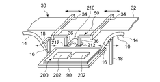
- FIG. 1 is a perspective view showing a schematic structure of a metal bonding apparatus according to Embodiment 1.
- FIG. FIG. 3 is an enlarged schematic view near the stage of the metal bonding apparatus according to the first embodiment.
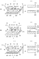
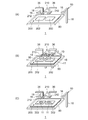
- FIGS. 3A to 3C are schematic diagrams for explaining the operation of the metal bonding apparatus.
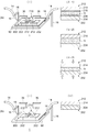
- 4A and 4B are schematic diagrams for explaining the operation of the metal bonding apparatus.
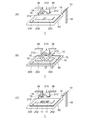
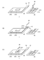
- FIGS. 5A to 5C are schematic diagrams for explaining the operation of the metal bonding apparatus according to the first modification.
- 6A to 6C are schematic diagrams for explaining the operation of the metal bonding apparatus according to the second modification.
- FIGS. 7A to 7C are schematic diagrams for explaining the operation of the metal bonding apparatus according to the third modification.
- FIGS. 9A to 9C are schematic views for explaining the operation of the metal bonding apparatus according to the fifth modification.
- FIGS. 10A to 10D are schematic views for explaining the operation of the metal bonding apparatus according to the sixth modification. It is a perspective view which shows schematic structure of the metal joining apparatus which concerns on Embodiment 2.
- FIG. 9A to 9C are schematic views for explaining the operation of the metal bonding apparatus according to the fifth modification.
- FIGS. 10A to 10D are schematic views for explaining the operation of the metal bonding apparatus according to the sixth modification. It is a perspective view which shows schematic structure of the metal joining apparatus which concerns on Embodiment 2.
- FIG. 9A to 9C are schematic views for explaining the
- the wiring board or the semiconductor chip may be damaged by heat or pressure.
- a large facility such as a vacuum apparatus is required, and an increase in cost is inevitable.
- FIG. 1 is a perspective view showing a schematic structure of the metal bonding apparatus according to the first embodiment.
- FIG. 2 is an enlarged schematic view of the vicinity of the stage of the metal bonding apparatus according to the first embodiment.
- FIG. 1 in order to show the internal structure of the metal bonding apparatus, a part of the lid of the metal bonding apparatus is not shown.
- the metal bonding apparatus 1 includes a solution supply unit 10, a pressurization unit 30, a heating unit 50, as main components in an accommodation space formed by the housing 2 and the lid 3. Is provided.
- the lid 3 has a window 3a through which the inside of the accommodation space can be observed, a monitor 4 for displaying various setting conditions and states of the metal bonding apparatus 1 such as a solution supply amount, pressure, and temperature, An exhaust pipe 5 for exhausting gas is provided.
- the housing 2 is provided with an operation unit 6 for instructing the setting of the operation of the metal bonding apparatus 1 and the start / stop of the operation. Further, a control unit 7 for executing various controls of the metal bonding apparatus 1 is accommodated in the accommodation space.
- the metal joining apparatus 1 which concerns on this embodiment, it has the 1st member supply part 70 in which the 1st member 200 which has the 1st to-be-joined part 202 is stored, and the 2nd to-be-joined part 212.
- a second member supply unit 80 in which the second member 210 is stored is provided.
- the first bonded portion 202 of the first member 200 and the second bonded portion 212 of the second member 210 are objects to be bonded by the metal bonding apparatus 1.
- a stage 90 is provided in the housing space where the first bonded portion 202 and the second bonded portion 212 are pressurized and heated.
- the first member supply unit 70, the stage 90, and the second member supply unit 80 are arranged in this order, and the arm rail extends so as to extend along the first member supply unit 70, the stage 90, and the second member supply unit 80.
- 32 is provided.
- the arm rail 32 is provided with two arms 34 so as to be slidable.
- Member holding portions 36 (chucks) are respectively provided at the tips of the two arms 34.
- the member holding portion 36 has a tip portion facing downward of the apparatus.
- a suction hole (both not shown) connected to the intake pump is provided at the tip of the member holding portion 36.
- the member holding portion 36 can adsorb and hold the member by driving the intake pump in a state where the member to be held is in contact with the tip portion.
- the member holding part 36 has a built-in heater, and the adsorbed member can be heated. Therefore, in the metal bonding apparatus 1 according to the present embodiment, the member holding unit 36 itself constitutes the heating unit 50.
- sequence order of the 1st member supply part 70, the 2nd member supply part 80, and the stage 90 is not specifically limited.
- the heater may be provided as a separate body outside the member holding portion 36.
- the arm rail 32 is disposed at a position that does not overlap the first member supply unit 70, the second member supply unit 80, and the stage 90 when the metal bonding apparatus 1 is viewed from above (in plan view).
- the arm 34 extends from the arm rail 32 toward the side where the first member supply unit 70, the second member supply unit 80, and the stage 90 are arranged.
- the member holding portion 36 connected to the tip of the arm 34 is disposed at a position overlapping the stage 90 in a plan view with the arm 34 positioned substantially at the center of the arm rail 32. As the arm 34 slides along the arm rail 32, the member holding unit 36 can move from above the stage 90 to above the first member supply unit 70 or the second member supply unit 80. Note that the two arms 34 can slide along the arm rail 32 independently of each other.
- Rail support portions 38 are connected to both ends of the arm rail 32.
- the rail support portion 38 is substantially L-shaped when viewed from the side of the apparatus, one end is fixed to the end of the arm rail 32, and the other end is located behind and below the apparatus with respect to the arm rail 32.
- the other end of the rail support portion 38 is connected to a drive mechanism (not shown) accommodated in the housing 2, and can be displaced in the vertical direction of the apparatus by this drive mechanism.
- the metal joining device 1 slides the arm 34 toward the first member supply unit 70, displaces the rail support unit 38 downward, and moves the tip of the member holding unit 36 closer to the first member supply unit 70.
- the first member 200 stored in the member supply unit 70 is sucked and held by the member holding unit 36.
- the rail support portion 38 is displaced upward in the apparatus, the tip of the member holding portion 36 is retracted from the first member supply portion 70, and the arm 34 is slid to the stage 90 side.
- the metal bonding apparatus 1 again displaces the rail support portion 38 downward, brings the tip of the member holding portion 36 closer to the stage 90, and places the first member 200 held by suction on the stage 90. .
- the arm rail 32, the arm 34, the member holding unit 36, and the rail support unit 38 include a first transport unit that transports the first member 200 having the first joined portion 202 to the stage 90, and a first transport unit.
- 2nd conveyance part which conveys the 2nd member 210 which has 2 joined parts 212 to stage 90 is constituted.
- the first member 200 is placed on the stage 90, and the first member 200 is displaced by moving the rail support portion 38 downward while the second member 210 is held by the member holding portion 36.
- the first bonded portion 202 and the second bonded portion 212 can be pressurized so as to reduce the distance between the bonded portion 202 and the second bonded portion 212 of the second member 210. Therefore, in the present embodiment, the arm rail 32, the arm 34, the member holding part 36, and the rail support part 38 constitute the pressurizing part 30.
- the solution tank 12 is fixed to the rail support portion 38.
- One end side of two solution supply tubes 14 is connected to the solution tank 12.
- Each of the two solution supply tubes 14 has the other end extending to the vicinity of the tip of the member holding portion 36, and the nozzle 16 is provided at the other end.
- the nozzle 16 has a dropper structure.
- Each nozzle 16 is connected to an arm 18 connected to a drive mechanism (not shown) housed in the housing 2. The arm 18 can make the nozzle 16 approach and retreat with respect to the bonding region between the first bonded portion 202 and the second bonded portion 212.
- the solution stored in the solution tank 12 is dropped from the nozzle 16 through the solution supply tube 14 in a state where the nozzle 16 is close to the joining region between the first joined portion 202 and the second joined portion 212 of the stage 90.
- the solution is supplied to at least one of the first bonded portion 202 and the second bonded portion 212. Therefore, in the present embodiment, the solution supply unit 10 is configured by the solution tank 12, the solution supply tube 14, the nozzle 16 and the arm 18.
- 3A to 3C, 4A, and 4B are schematic diagrams for explaining the operation of the metal bonding apparatus.
- (I) in each figure is an enlarged schematic view in the vicinity of the stage, and (ii) ((ii-1) to (ii-3) in FIG. 4A) shows the first joined portion and the second joined portion.
- It is a schematic diagram which shows the state of a to-be-joined part.
- 3A to 3C, 4A, and 4B the illustration of the arm rail 32, the arm 34, and the like is omitted.
- you may provide the solution heating part which heats the solution 11 previously by attaching a heater to the solution tank 12. By doing so, in the joining process described later, the solution 11 can be evaporated in a short time, and the entire joining process can be shortened.
- the metal joining apparatus 1 transports the first member 200 having the first joined portion 202 from the first member supply portion 70 and places it on the stage 90, and then places the second subject.
- the second member 210 having the joint portion 212 is held by the member holding portion 36 and disposed above the first member 200.
- the first bonded portion 202 includes a first base material portion 204 made of a metal whose main component is copper, and a first coating portion 206 that covers the surface of the first base material portion 204 on the bonding surface side.
- the second bonded portion 212 includes a second base material portion 214 made of a metal whose main component is copper, and a second coating portion 216 that covers the surface of the second base material portion 214 on the bonding surface side. .
- Both the first coating portion 206 and the second coating portion 216 are formed of an oxide containing copper oxide as a main component.
- “mainly composed of copper” and “mainly composed of copper oxide” means that the content of copper or copper oxide is larger than 50%. .
- the 1st base material part 204 and the 2nd base material part 214 should just be formed with the metal which has copper as a main component, and the form in particular is not restrict
- the first base material portion 204 and the second base material portion 214 may be, for example, a deposited layer made of copper formed on a substrate such as a Si substrate by a sputtering method, and patterning a copper plate such as a copper foil.
- the external terminal portion of the wiring layer formed by the above may be used.
- the first film part 206 and the second film part 216 are thin film films formed of Cu 2 O, CuO, or the like, and the thickness thereof is, for example, 10 nm.
- the first film part 206 and the second film part 216 may be a film formed intentionally or a film formed unintentionally.
- the first coating portion 206 and the second coating portion 216 are natural oxide films formed by oxidizing copper in the atmosphere.
- the metal bonding apparatus 1 uses the arm 18 so that the tip of the nozzle 16 is positioned between the first bonded portion 202 and the second bonded portion 212. Move. Then, the solution 11 is dropped from the nozzle 16 onto the surface of the first coating part 206. As a result, as shown in FIG. 3C, the solution 11 is applied to the surface of the first coating part 206. Thereby, the solution 11 in which the oxide mainly composed of copper oxide is eluted or dissolved is supplied between the first coating portion 206 and the second coating portion 216.
- the metal bonding apparatus 1 displaces the nozzle 18 from the space sandwiched between the second member 210 and the second bonded portion 212 by displacing the arm 18.
- the solution 11 is ammonia water.
- the solution 11 may be applied to the second bonded portion 212 side.
- the metal bonding apparatus 1 includes a solution 11 in which the second coating portion 216 of the second bonded portion 212 is applied onto the first coating portion 206 of the first bonded portion 202.
- the member holding portion 36 is moved closer to the stage 90 until it comes into contact with (see (ii-1) in FIG. 4A).
- the copper oxide constituting the first coating portion 206 and the second coating portion 216 is eluted into the solution 11 (see (ii-2) in FIG. 4A).
- the first base material portion 204 and the second base member are respectively formed on the outermost surface (exposed surface on the bonding surface side) of the first bonded portion 202 and the outermost surface (exposed surface on the bonding surface side) of the second bonded portion 212. Copper constituting the material part 214 is exposed. Further, in the solution 11, a copper complex is formed by ammonia ions and copper ions serving as ligands. In the present embodiment, the copper complex is considered to exist as a thermally decomposable tetraammine copper complex ion represented by [Cu (NH 3 ) 4 ] 2+ . In addition, since ammonia water is inactive with respect to copper, the copper which comprises the 1st base material part 204 and the 2nd base material part 214 remains without reacting with ammonia water.
- the metal bonding apparatus 1 causes the member holding portion 36 to further approach the stage 90 and the first bonded portion 202 and the second bonded portion so that the distance between the first bonded portion 202 and the second bonded portion 212 is reduced.
- the portion 212 is pressurized (see (ii-3) in FIG. 4A).
- the pressure at the time of pressurization is 1 MPa, for example.
- the metal bonding apparatus 1 uses the member holding portion 36 to perform the second bonded at a relatively low temperature of 200 ° C. to 300 ° C.
- the part 212, the solution 11, and the first joined part 202 are heated.
- moisture is evaporated by heating, and the tetraammine copper complex ions are thermally decomposed to evaporate the ammonia component.
- the ratio of copper gradually increases in the solution 11, and the distance between the outermost surface of the first bonded portion 202 and the outermost surface of the second bonded portion 212 is reduced by the pressurization by the pressurizing unit 30.
- the copper exposed on the surface of the first bonded portion 202 due to the approach between the outermost surface of the first bonded portion 202 and the outermost surface of the second bonded portion 212.
- Solid phase diffusion of copper exposed on the surface of the second bonded portion 212 occurs.
- the 1st to-be-joined part 202 and the 2nd to-be-joined part 212 are joined.
- the metal joining apparatus 1 stops heating by the member holding unit 36 and retracts the member holding unit 36 from the stage 90 to release the pressure. With the above processing, the joining of the first joined portion 202 and the second joined portion 212 is completed.
- the time from the start to the stop of heating is, for example, 30 seconds.
- the first bonded portion 202 and the second bonded portion 212 are heated after pressurization, but the order of pressurization and heating is not particularly limited, and is heated before pressurization. It may be simultaneous. For example, you may press the 2nd to-be-joined part 212 heated beforehand against the 1st to-be-joined part 202 which apply
- the first film portion 206 and the second film portion 216 are eluted into the solution 11, thereby bonding the first bonded portion 202 and the second bonded portion 212. Copper is exposed on each surface.
- the bonding surfaces of the first bonded portion 202 and the second bonded portion 212 are activated.
- bonding is performed by solid phase diffusion of exposed copper. Thereby, copper can be joined under comparatively low temperature conditions. Also, copper can be bonded under relatively low pressure conditions.
- the solution 11 is dripped from the nozzle 16 that is brought close to the joining region between the first joined portion 202 and the second joined portion 212, an appropriate amount of the solution 11 can be locally supplied. Thereby, it can be avoided that the solution 11 scatters to the surroundings at the time of pressurization and the first member 200 and the second member 210 are corroded and that the joining time is increased due to an excessive supply amount of the solution 11. it can.
- ammonia water is used as the solution 11 used for metal bonding.
- the solution is not limited to this as long as the solution includes a ligand that forms a complex with copper.
- a carboxylic acid aqueous solution may be used.
- carboxylic acid used for the preparation of the aqueous carboxylic acid solution examples include monocarboxylic acids such as acetic acid, dicarboxylic acids such as oxalic acid, malonic acid, succinic acid, glutaric acid, phthalic acid, and maleic acid, and tartaric acid and citric acid. And oxycarboxylic acids such as lactic acid and salicylic acid.
- the carboxylic acid aqueous solution preferably has a carboxylic acid to be a multidentate ligand.
- a carboxylic acid aqueous solution having a carboxylic acid to be a multidentate ligand at least two ligands of the carboxylic acid coordinate to one copper ion, and the carboxylic acid and copper form a chelate to form a copper complex.
- the formation of chelates by tartaric acid is described on page 593 of “Science and Chemistry Dictionary, 4th edition (Iwanami Shoten)”.
- chelation means that the stability of the complex is greatly increased by forming a ring with a multidentate ligand.
- the solution supply unit 10 includes a spray nozzle that sprays the solution 11 on at least one of the first bonded portion 202 and the second bonded portion 212. That is, in this modification, the nozzle 16 is a spray nozzle.
- the metal bonding apparatus 1 according to Modification 1 will be described with reference to FIGS. 5 (A) to 5 (C).
- FIGS. 5A to 5C are schematic views for explaining the operation of the metal joining apparatus according to the first modification.
- 5A to 5C schematically show the vicinity of the stage, and the illustration of the arm rail 32, the arm 34, the solution supply tube 14, and the like is omitted.
- the metal bonding apparatus 1 places the first member 200 having the first bonded portion 202 on the stage 90, and the second member 210 having the second bonded portion 212. It is held by the member holding part 36 and arranged above the first member 200.
- the metal bonding apparatus 1 moves the nozzle 16 by the arm 18 so that the nozzle 16 is positioned between the first bonded portion 202 and the second bonded portion 212.
- the solution 11 is sprayed from the nozzle 16 onto the surface of the first bonded portion 202.
- the solution 11 is applied to the surface of the first bonded portion 202.
- the metal bonding apparatus 1 retracts the nozzle 16 from the space sandwiched between the second member 210 and the second bonded portion 212.
- the solution 11 may be applied to the second bonded portion 212 side. Subsequent operations are the same as those in FIGS. 4A and 4B, and a description thereof will be omitted.
- the nozzle 16 is a spray nozzle, the solution 11 can be uniformly applied to the surface of the first coating portion 206 or the second coating portion 216, and the solution 11 is applied excessively. Can be suppressed.
- the solution supply unit 10 includes an inkjet nozzle that discharges the solution 11 to at least one of the first bonded portion 202 and the second bonded portion 212. That is, in this modification, the nozzle 16 is an inkjet nozzle.
- the metal bonding apparatus 1 according to Modification 2 will be described with reference to FIGS. 6 (A) to 6 (C).
- 6 (A) to 6 (C) are schematic diagrams for explaining the operation of the metal bonding apparatus according to the second modification.
- 6A to 6C schematically show the vicinity of the stage, and the illustration of the arm rail 32, the arm 34, the solution supply tube 14 and the like is omitted.
- the metal bonding apparatus 1 places the first member 200 having the first bonded portion 202 on the stage 90 and the second member 210 having the second bonded portion 212. It is held by the member holding part 36 and arranged above the first member 200.
- the metal bonding apparatus 1 moves the nozzle 16 by the arm 18 so that the nozzle 16 is positioned between the first bonded portion 202 and the second bonded portion 212. Let Then, the solution 11 is discharged from the nozzle 16 onto the surface of the first bonded portion 202.
- the metal bonding apparatus 1 discharges the solution 11 onto the surface of the first bonded portion 202 while scanning the nozzle 16 so that the solution 11 is applied to a preset region.
- the region to which the solution 11 is applied is input in advance from the operation unit 6 to the control unit 7, for example.
- the solution 11 is applied to the surface of the first bonded portion 202.
- the metal bonding apparatus 1 retracts the nozzle 16 from the space sandwiched between the second member 210 and the second bonded portion 212.
- the solution 11 may be applied to the second bonded portion 212 side. Subsequent operations are the same as those in FIGS. 4A and 4B, and a description thereof will be omitted.
- nozzle 16 is an inkjet nozzle
- various shapes of solution application regions can be formed in accordance with the shape of the first bonded portion 202 or the second bonded portion 212.
- the solution supply unit 10 includes a shower head that sprays the solution 11 on at least one of the first bonded portion 202 and the second bonded portion 212. That is, in this modification, the nozzle 16 is a shower head.
- the metal bonding apparatus 1 according to Modification 3 will be described with reference to FIGS. 7 (A) to 7 (C).
- 7A to 7C are schematic diagrams for explaining the operation of the metal bonding apparatus according to the third modification.
- 7A to 7C schematically show the vicinity of the stage, and illustration of the arm rail 32, the arm 34, the solution supply tube 14 and the like is omitted.
- the metal bonding apparatus 1 places the first member 200 having the first bonded portion 202 on the stage 90, and the second member 210 having the second bonded portion 212. It is held by the member holding part 36 and arranged above the first member 200.
- the metal bonding apparatus 1 moves the nozzle 16 by the arm 18 so that the nozzle 16 is positioned between the first bonded portion 202 and the second bonded portion 212.
- the solution 11 is discharged from the nozzle 16 to the surface of the first bonded portion 202.
- the solution 11 is applied to the surface of the first bonded portion 202.
- the metal bonding apparatus 1 retracts the nozzle 16 from the space sandwiched between the second member 210 and the second bonded portion 212.
- the solution 11 may be applied to the second bonded portion 212 side. Subsequent operations are the same as those in FIGS. 4A and 4B, and a description thereof will be omitted.
- the nozzle 16 is a shower head, it can be suitably employed when the area where the solution 11 is applied is relatively wide.
- the solution supply unit 10 includes a partition wall that surrounds a region to which the solution 11 is supplied in at least one of the first bonded section 202 and the second bonded section 212.
- the solution 11 is supplied to the area covered with.
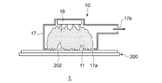
- FIG. 8 is a schematic diagram for explaining the operation of the metal bonding apparatus according to the fourth modification.
- FIG. 8 schematically shows the vicinity of the nozzle and the first bonded portion.
- the nozzle 16 shown in FIG. 8 is a spray nozzle.
- the metal bonding apparatus 1 has a partition wall (clamper) 17 surrounding the periphery of the nozzle 16.
- the partition wall portion 17 has a substantially casing shape, and the nozzle 16 is fixed to the inner wall of the upper surface. Further, an opening 17a through which the solution 11 sprayed from the nozzle 16 is sent to the outside is provided on the lower surface, and an exhaust port 17b is provided on the side wall.
- the opening 17 a has the same shape as the shape of the application region of the solution 11.
- the region for supplying the solution 11 is surrounded by the partition wall 17. Therefore, when the solution 11 is sprayed from the nozzle 16, the solution 11 is applied only to a region covered with the partition wall portion 17, that is, a region overlapping with the opening 17 a of the partition wall portion 17.
- the nozzle 16 is not limited to a spray nozzle, and may be a dropper, a shower head, or the like.
- the solution 11 can be applied only to the region to which the solution 11 is to be applied, that is, the bonded portion, and the solution 11 is applied to other regions. Can be prevented from scattering.
- FIGS. 9A to 9C are schematic views for explaining the operation of the metal bonding apparatus according to the fifth modification. 9A to 9C, the illustration of the arm 18, the arm rail 32, the arm 34, and the like is omitted.
- the metal bonding apparatus 1 has a container 19 for the solution 11.
- the solution supply tube 14 (see FIG. 1) is connected to the container 19 and the solution 11 in the solution tank 12 (see FIG. 1) is supplied to the container 19 via the solution supply tube 14.
- a container can be mentioned, for example.
- a porous material such as sponge impregnated with the solution 11 may be used.
- the metal bonding apparatus 1 places the first member 200 having the first bonded portion 202 on the stage 90. Further, the member holding part 36 is moved above the second member supply part 80 to hold the second member 210 having the second joined part 212 by suction.
- the metal bonding apparatus 1 moves the member holding part 36 onto the accommodating part 19 and displaces the member holding part 36 below the apparatus to hold it at the tip.
- the second bonded portion 212 of the second member 210 is immersed in the housing portion 19, and the solution 11 is applied to the second bonded portion 212.
- the metal bonding apparatus 1 moves the member holding portion 36 onto the stage 90. Then, the member holding portion 36 is moved closer to the stage 90 until the solution 11 applied to the second bonded portion 212 comes into contact with the first bonded portion 202. Subsequent operations are the same as those in FIGS. 4A and 4B, and a description thereof will be omitted.
- the solution 11 may be applied to the first bonded portion 202 side. Of the first member 200 having the first bonded portion 202 and the second member 210 having the second bonded portion 212, the solution 11 may be applied. It is preferable to contact the solution 11 with a smaller area of a region located on the same plane as the first bonded portion 202 or the second bonded portion 212. Thereby, it can avoid that the solution 11 adheres to area
- the structure of the solution supply portion 10 can be simplified. it can.
- the solution supply unit 10 includes a soft porous body that can be impregnated with the solution 11, and the porous body impregnated with the solution 11 is the first bonded portion 202 and the first bonded body. 2 Press against at least one of the joined parts 212.
- the metal bonding apparatus 1 according to Modification 6 will be described with reference to FIGS. 10 (A) to 10 (D).
- FIGS. 10A to 10D are schematic views for explaining the operation of the metal bonding apparatus according to the sixth modification. 10A to 10D schematically show the vicinity of the stage, and the illustration of the arm rail 32, the arm 34, and the like is omitted.
- the metal bonding apparatus 1 has a soft porous body 20 that can be impregnated with the solution 11.
- Examples of the porous body 20 include a sponge.
- An arm 18 is connected to the porous body 20.
- the metal bonding apparatus 1 has a storage unit 19 for the solution 11.
- the solution supply tube 14 (see FIG. 1) is connected to the container 19 and the solution 11 in the solution tank 12 (see FIG. 1) is supplied to the container 19 via the solution supply tube 14.
- a container (bat) can be mentioned, for example.
- the metal bonding apparatus 1 immerses the porous body 20 in the housing part 19 and impregnates the porous body 20 with the solution 11 in the housing part 19. Further, the metal bonding apparatus 1 places the first member 200 having the first bonded portion 202 on the stage 90 and holds the second member 210 having the second bonded portion 212 by the member holding portion 36.
- the first member 200 is disposed above the first member 200.
- the metal bonding apparatus 1 is porous by the arm 18 so that the porous body 20 is positioned between the first bonded portion 202 and the second bonded portion 212.
- the body 20 is moved.
- the member holding part 36 is brought close to the stage 90, and the porous body 20 impregnated with the solution 11 is sandwiched between the first joined part 202 and the second joined part 212. Thereby, the solution 11 is applied to the first bonded portion 202 and the second bonded portion 212.
- the metal bonding apparatus 1 moves the member holding part 36 backward from the stage 90 and returns the porous body 20 to the housing part 19. Subsequent operations are the same as those in FIGS. 4A and 4B, and a description thereof will be omitted.
- the porous body 20 may be pressed against the first bonded portion 202 or the second bonded portion 212, and the solution 11 may be applied only to the first bonded portion 202 side or the second bonded portion 212 side.
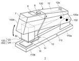
- FIG. 11 is a perspective view illustrating a schematic structure of the metal bonding apparatus according to the second embodiment.
- the metal bonding apparatus 1 includes a first arm part 100 and a second arm part 110.
- the second arm portion 110 has one end 110 a side thereof rotatably connected to the one end 100 a side of the first arm portion 100.
- the one end 100a side of the first arm portion 100 and the one end 110a side of the second arm portion 110 are connected by a movable portion 102 such as a hinge so as to be relatively rotatable. Therefore, the first arm portion 100 and the second arm portion 110 can be operated so that the other end 100b side of the first arm portion 100 and the other end 110b side of the second arm portion 110 are relatively close to each other.
- a pair of pedestals 120 are provided on the opposing surfaces of the other end 100 b of the first arm 100 and the other end 110 b of the second arm 110.
- the pair of pedestals 120 includes a first pedestal 122 provided on the first arm portion 100 and a second pedestal 124 provided on the second arm portion 110.
- a space into which the first bonded portion 202 and the second bonded portion 212 are inserted is formed between the pair of pedestals 120 in a state where the first arm portion 100 and the second arm portion 110 are not operated.
- the first arm portion 100 and the second arm portion 110 are rotated relative to each other about the movable portion 102, whereby the other end 100b side of the first arm portion 100 and the other end 110b side of the second arm portion 110.
- the first bonded portion 202 and the second bonded portion 212 inserted into the space between the first pedestal 122 and the second pedestal 124 can be pressurized. Therefore, in the metal bonding apparatus 1 according to the present embodiment, the first arm portion 100, the second arm portion 110, and the pair of pedestals 120 are included in the pressurizing unit 30.
- the first pedestal 122 and the second pedestal 124 of the pair of pedestals 120 contain heaters, respectively, and the first and second joined portions 202 and 202 are inserted by the first pedestal 122 and the second pedestal 124. Portion 212 can be heated. Therefore, in the metal bonding apparatus 1 according to the present embodiment, the pair of pedestals 120 constitutes the heating unit 50.
- the solution tank 12 is provided on the side of the first arm 100 opposite to the second arm 110 on the one end 100a side.
- the solution tank 12 is provided with a solution inlet 12a for filling the solution 11 into the tank.
- a nozzle 16 is provided on the other end 100 b side of the first arm portion 100.
- the nozzle 16 supplies the solution 11 in the solution tank 12 to at least one of the first bonded portion 202 and the second bonded portion 212 inserted into the space between the first pedestal 122 and the second pedestal 124.
- the solution tank 12 and the nozzle 16 are connected by a solution supply tube 14 laid inside the first arm 100.
- a control unit 7 is provided adjacent to the solution tank 12 on the surface of the first arm 100 opposite to the second arm 110.
- An operation unit 6 and a solution supply button 8 are provided on the upper surface of the control unit 7.
- the operation unit 6 may have a display function such as a set temperature and a remaining amount of solution. That is, the monitor 4 may be incorporated. By pressing the solution supply button 8, the solution 11 in the solution tank 12 can be sent out from the nozzle 16.
- the operation method of the metal bonding apparatus 1 is as follows. First, the user holds the metal bonding apparatus 1 and inserts the first bonded portion 202 (see FIG. 2) between the first pedestal 122 and the second pedestal 124. Then, the solution supply button 8 is pressed to supply the solution 11 to the first bonded portion 202. Subsequently, a second bonded portion 212 (see FIG. 2) is inserted between the first bonded portion 202 and the first pedestal 122, and the first arm portion 100 and the second arm portion 110 are pivoted about the movable portion 102. Operate to rotate. As a result, the solution 11 supplied to the first bonded portion 202 comes into contact with the second bonded portion 212.
- the 1st to-be-joined part 202 and the 2nd to-be-joined part 212 are pressurized by further pushing operation. Then, in a state where the first bonded portion 202 and the second bonded portion 212 are pressurized, the first bonded portion 202 and the second bonded portion 212 are pressed by the pair of pedestals 120. By the above operation, the first bonded portion 202 and the second bonded portion 212 can be bonded.
- the pressurizing operation of the metal bonding apparatus 1 conforms to the stapler operation.
- the user can perform a pressurizing process by causing the first arm portion 100 and the second arm portion 110 to approach the axis of the movable portion 102 by a grip operation.
- the second arm part 110 can be fixed on a desk or the like, and the first arm part 100 can be pressed down with the movable part 102 as an axis to perform the pressure treatment.
- the first bonded portion and the second bonded portion are both copper, but one or both of the first bonded portion and the second bonded portion may be a metal other than copper. it can.
- the first bonded portion may be copper and the second bonded portion may be aluminum.
- the first bonded portion may be iron and the second bonded portion may be aluminum.
- heating and pressurization are performed when the first bonded portion and the second bonded portion are metal-bonded, but ultrasonic waves are applied instead of heating and pressing.
- heating or pressurization may be replaced with ultrasonic application, or ultrasonic waves may be applied in addition to heating and pressurization.
- [Item 1] 1st to-be-joined part which has the 1st base material part which consists of a metal which has copper as a main component, and the 1st film part which consists of the oxide which has copper oxide as a main component, and coat
- a solution supply unit that supplies a solution from which an oxide mainly composed of copper oxide elutes to at least one of the second coating portions of the second bonded portion including: A pressure unit that pressurizes the first bonded part and the second bonded part so as to reduce a distance between the first bonded part and the second bonded part; A heating part for heating the first joined part and the second joined part, Bonding the copper of the first bonded portion and the copper of the second bonded portion exposed by the solution in a state where
- a metal bonding apparatus characterized by.
- the solution supply unit includes an inkjet nozzle that discharges the solution to at least one of the first bonded portion and the second bonded portion.
- the solution supply unit includes a partition wall that surrounds a region for supplying a solution in at least one of the first bonded portion and the second bonded portion.
- the metal bonding apparatus includes a storage unit for the solution, and contacts at least one of the first bonded unit and the second bonded unit with the solution in the storage unit.
- the solution supply part is on the same plane as the first joined part or the second joined part among the first member having the first joined part and the second member having the second joined part.
- Item 6 The metal bonding apparatus according to Item 5, wherein a region having a smaller area is brought into contact with the solution.
- the solution supply section includes a porous body that can be impregnated with the solution, and the porous body impregnated with the solution is pressed against at least one of the first bonded section and the second bonded section.
- Metal bonding apparatus as described in. [Item 8] 8. The metal joining apparatus according to item 7, wherein the solution supply unit sandwiches the porous body impregnated with the solution between the first joined portion and the second joined portion. [Item 9] The metal bonding apparatus according to item 1, wherein the solution supply unit includes a solution heating unit that heats the solution. [Item 10] A stage on which pressurization and heating of the first bonded portion and the second bonded portion are performed; A first transport unit that transports the first member having the first joined portion to the stage; A second transport unit that transports the second member having the second joined portion to the stage; 10.
- the metal bonding apparatus according to any one of items 1 to 9, further comprising: [Item 11] A first arm portion, and a second arm portion whose one end side is rotatably connected to one end side of the first arm portion, and a second arm portion operable to approach the other end side of the first arm portion.
- the pressurizing unit has a pair of pedestals provided on opposite surfaces of the other end side of the first arm unit and the other end side of the second arm unit, and between the pair of pedestals, A space into which the first joined portion and the second joined portion are inserted is formed, and the other end side of the first arm portion and the other end side of the second arm portion are inserted into the space. Item 2.
- the metal bonding apparatus according to Item 1, wherein the first bonded portion and the second bonded portion are pressurized.
- the solution supply unit includes a solution tank provided in the first arm portion and the first joint to be provided on the other end side of the first arm portion, and the solution in the solution tank is inserted into the space. And a nozzle for supplying at least one of the second bonded portion and the second bonded portion.
- the heating unit includes a heater accommodated in the pair of pedestals.
- the solution includes a ligand that forms a complex with copper.
- [Item 16] 16 The metal bonding apparatus according to any one of items 1 to 15, wherein the solution is ammonia water or a carboxylic acid aqueous solution.
- the carboxylic acid contained in the carboxylic acid aqueous solution is a multidentate ligand.
- Item 18 Item 18. The metal bonding apparatus according to Item 17, wherein among the multidentate ligands, at least two ligands are coordinated to one copper ion.
- 1 metal bonding apparatus 10 solution supply unit, 11 solution, 12 solution tank, 16 nozzle, 17 partition unit, 19 accommodating unit, 20 porous body, 30 pressurizing unit, 50 heating unit, 90 stage, 100 first arm unit , 100a one end, 100b other end, 110 second arm part, 110a one end, 110b other end, 120 pair of pedestals, 200 first member, 202 first joined part, 204 first base part, 206 first coating part 210, second member, 212, second bonded portion, 214, second base material portion, 216, second coating portion.
- the present invention can be used for a metal bonding apparatus.
Landscapes
- Engineering & Computer Science (AREA)
- Mechanical Engineering (AREA)
- Pressure Welding/Diffusion-Bonding (AREA)
Abstract
金属接合装置(1)は、銅を主成分とする第1基材部と、酸化銅を主成分とする第1被膜部とを有する第1被接合部の第1被膜部、および銅を主成分とする第2基材部と、酸化銅を主成分とする第2被膜部とを有する第2被接合部の第2被膜部の少なくとも一方に、酸化銅を主成分とする酸化物が溶出する溶液を供給する溶液供給部(10)と、第1被接合部と第2被接合部との間の距離を縮めるように第1被接合部と第2被接合部とを加圧する加圧部(30)と、第1被接合部および第2被接合部を加熱する加熱部(50)と、を備える。
Description
本発明は、金属接合装置に関する。より具体的には、銅と銅の接合装置に関する。
配線基板を構成する配線層や半導体チップの素子電極表面等の導電性材料として、銅が幅広く使用されている。従来、配線基板の配線層等の第1の被接合部材に半導体チップの素子電極など第2の被接合部材を電気的に接続する金属の接合方法としては、はんだを介して接合面をはんだ接合する方法、接合面を高温に加熱しながら加圧下で接合する方法、真空中でイオン照射等により接合面を活性化させて接合する方法などが知られている。
はんだを介して銅同士を接合する従来の方法では、接合部分の接続信頼性を向上させる余地があった。また、接合面を高温に加熱する従来の方法では、配線基板や半導体チップにダメージが生じるおそれがあった。
本発明はこうした課題に鑑みてなされたものであり、その目的は、接続信頼性を確保しつつ、比較的低温で銅同士を接合することのできる技術の提供にある。
本発明のある態様は、金属接合装置である。当該金属接合装置は、銅を主成分とする金属からなる第1基材部と、酸化銅を主成分とする酸化物からなり第1基材部の表面を被覆する第1被膜部とを有する第1被接合部の第1被膜部、および銅を主成分とする金属からなる第2基材部と、酸化銅を主成分とする酸化物からなり第2基材部の表面を被覆する第2被膜部とを有する第2被接合部の第2被膜部の少なくとも一方に、酸化銅を主成分とする酸化物が溶出する溶液を供給する溶液供給部と、第1被接合部と第2被接合部との間の距離を縮めるように第1被接合部と第2被接合部とを加圧する加圧部と、第1被接合部および第2被接合部を加熱する加熱部と、を備え、第1被接合部と第2被接合部とを加圧および加熱した状態で、溶液により露出した第1被接合部の銅と第2被接合部の銅とを接合することを特徴とする。
本発明によれば、接続信頼性を確保しつつ、比較的低温で銅同士を接合することのできる技術を提供することができる。
以下、本発明の実施の形態を図面を参照して説明する。なお、すべての図面において、同様な構成要素には同様の符号を付し、適宜説明を省略する。まず、実施の形態を具体的に説明する前に、基礎となった知見を説明する。従来行われていた、はんだを介して銅同士を接合する方法において、通常使用されるSnを成分とするはんだを用いた場合、銅とはんだとの接合界面にCu-Sn合金が生じる。Cu-Sn合金は電気抵抗が比較的大きく、かつ延性が乏しいため、接合部分の電気特性や接続信頼性が低下するという課題がある。また、接合面を高温に加熱して加圧により接合する方法では、配線基板や半導体チップに熱や加圧によるダメージが生じる可能性がある。また、真空中で接合面を活性化させて接合する方法では、真空装置などの大がかりな設備が必要となりコストの増大が避けられない。
(実施形態1)
図1は、実施形態1に係る金属接合装置の概略構造を示す斜視図である。図2は、実施形態1に係る金属接合装置のステージ近傍の拡大模式図である。なお、図1では、金属接合装置の内部の構造を示すために、金属接合装置の蓋体の一部の図示を省略している。
図1は、実施形態1に係る金属接合装置の概略構造を示す斜視図である。図2は、実施形態1に係る金属接合装置のステージ近傍の拡大模式図である。なお、図1では、金属接合装置の内部の構造を示すために、金属接合装置の蓋体の一部の図示を省略している。
本実施形態に係る金属接合装置1は、筐体2と、蓋体3とで形成される収容空間内に、主な構成として溶液供給部10と、加圧部30と、加熱部50と、を備える。蓋体3には、収容空間内を観察可能な窓部3aと、溶液供給量、圧力、温度などの金属接合装置1の各種設定条件や状態を表示するためのモニタ4と、収容空間内の気体を排出するための排気管5が設けられている。筐体2には、金属接合装置1の動作の設定、動作の開始停止等の指示を行うための操作部6が設けられている。また、収容空間内には、金属接合装置1の各種制御を実行するための制御ユニット7が収容されている。
また、本実施形態に係る金属接合装置1の収容空間内には、第1被接合部202を有する第1部材200が格納される第1部材供給部70と、第2被接合部212を有する第2部材210が格納される第2部材供給部80とが設けられている。第1部材200の第1被接合部202と、第2部材210の第2被接合部212とが、金属接合装置1による接合の対象となる。また、収容空間内には、第1被接合部202および第2被接合部212の加圧および加熱が行われるステージ90が設けられている。
第1部材供給部70、ステージ90および第2部材供給部80は、この順に配列されており、第1部材供給部70、ステージ90および第2部材供給部80に沿って延在するようアームレール32が設けられている。アームレール32には、スライド可能に2つのアーム34が設けられている。2つのアーム34の先端には、それぞれ部材保持部36(チャック)が設けられている。部材保持部36は、先端部が装置下方を向いている。部材保持部36の先端部には、吸気ポンプに連結された吸着孔(ともに図示せず)が設けられている。部材保持部36は、保持しようとする部材を先端部に当接させた状態で吸気ポンプを駆動させることで、部材を吸着して保持することができる。また、部材保持部36には、ヒータが内蔵されており、吸着した部材を加熱することができる。したがって、本実施形態に係る金属接合装置1では、部材保持部36自体が加熱部50を構成している。なお、第1部材供給部70、第2部材供給部80およびステージ90の配列順序は特に限定されない。また、ヒータは部材保持部36の外部に別体として設けられていてもよい。
アームレール32は、金属接合装置1を上方から見て(平面視で)、第1部材供給部70、第2部材供給部80およびステージ90と重ならない位置に配置されている。アーム34は、アームレール32から第1部材供給部70、第2部材供給部80およびステージ90が並ぶ側に向けて延在している。アーム34の先端に連結された部材保持部36は、アーム34がアームレール32の略中央に位置する状態で、平面視でステージ90と重なる位置に配置されている。アーム34がアームレール32に沿ってスライドすることで、部材保持部36はステージ90上から第1部材供給部70あるいは第2部材供給部80の上方に移動することができる。なお、2つのアーム34は、互いに独立にアームレール32に沿ってスライド可能である。
アームレール32の両端部には、レール支持部38が接続されている。レール支持部38は、装置側方から見て略L字形状であり、一端がアームレール32の端部に固定され、他端がアームレール32に対して装置後方かつ下方に位置している。レール支持部38は、他端が筐体2内に収容された駆動機構(図示せず)に連結されており、この駆動機構によって装置上下方向に変位することができる。レール支持部38が装置上下方向に変位すると、アームレール32、アーム34および部材保持部36がレール支持部38に連動して装置上下方向に変位する。これにより、部材保持部36の先端部を第1部材供給部70、第2部材供給部80あるいはステージ90に対して接近後退させることができる。
金属接合装置1は、アーム34を第1部材供給部70側にスライドさせ、レール支持部38を装置下方に変位させて部材保持部36の先端を第1部材供給部70に接近させ、第1部材供給部70に格納された第1部材200を部材保持部36で吸着保持する。そして、レール支持部38を装置上方に変位させて部材保持部36の先端を第1部材供給部70から後退させ、アーム34をステージ90側にスライドさせる。その後、金属接合装置1は、再びレール支持部38を装置下方に変位させて部材保持部36の先端をステージ90に接近させ、吸着保持していた第1部材200をステージ90上に載置する。同様に、第2部材210についても、第2部材供給部80からステージ90上に搬送することができる。したがって、本実施形態では、アームレール32、アーム34、部材保持部36およびレール支持部38が、第1被接合部202を有する第1部材200をステージ90に搬送する第1搬送部と、第2被接合部212を有する第2部材210をステージ90に搬送する第2搬送部とを構成している。
また、ステージ90上に第1部材200が載置され、部材保持部36で第2部材210を保持した状態で、レール支持部38を装置下方に変位させることで、第1部材200の第1被接合部202と第2部材210の第2被接合部212との間の距離を縮めるように第1被接合部202と第2被接合部212とを加圧することができる。したがって、本実施形態では、アームレール32、アーム34、部材保持部36およびレール支持部38が、加圧部30を構成している。
レール支持部38には、溶液タンク12が固定されている。溶液タンク12には、2本の溶液供給チューブ14の一端側が連結されている。2本の溶液供給チューブ14は、それぞれ他端側が部材保持部36の先端部近傍まで延在しており、その他端にノズル16が設けられている。本実施形態では、ノズル16はスポイト構造を有する。それぞれのノズル16には、筐体2内に収容された駆動機構(図示せず)に接続されたアーム18が連結されている。アーム18は、ノズル16を第1被接合部202と第2被接合部212との接合領域に対して接近後退させることができる。ノズル16がステージ90の第1被接合部202と第2被接合部212との接合領域に接近した状態で、溶液タンク12に貯留された溶液が溶液供給チューブ14を通ってノズル16から滴下される。これにより、第1被接合部202および第2被接合部212の少なくとも一方に、溶液が供給される。したがって、本実施形態では、溶液タンク12、溶液供給チューブ14、ノズル16およびアーム18により溶液供給部10が構成されている。
続いて、本実施形態に係る金属接合装置1の動作について説明する。以下に説明する動作は、制御ユニット7によって制御される。図3(A)~図3(C)、図4(A)および図4(B)は、金属接合装置の動作を説明するための模式図である。各図における(i)は、ステージ近傍の拡大模式図であり、(ii)(図4(A)については(ii-1)~(ii-3))は、第1被接合部および第2被接合部の状態を示す模式図である。なお、図3(A)~図3(C)、図4(A)および図4(B)では、アームレール32、アーム34等の図示を省略している。なお、溶液タンク12にヒータを取り付けることで、溶液11を予め加温する溶液加温部を備えてもよい。そうすることで、後述の接合工程において、溶液11を短時間で蒸発させることができ、接合工程全体の短縮を図ることができる。
図3(A)に示すように、金属接合装置1は、第1被接合部202を有する第1部材200を第1部材供給部70から搬送してステージ90上に載置し、第2被接合部212を有する第2部材210を部材保持部36により保持して、第1部材200の上方に配置する。第1被接合部202は、銅を主成分とする金属からなる第1基材部204と、第1基材部204の接合面側の表面を被覆する第1被膜部206とを有する。また、第2被接合部212は、銅を主成分とする金属からなる第2基材部214と、第2基材部214の接合面側の表面を被覆する第2被膜部216とを有する。第1被膜部206および第2被膜部216はともに酸化銅を主成分とする酸化物で形成されている。ここで、「銅を主成分とする」および「酸化銅を主成分とする」という表現中、「主成分とする」は、銅または酸化銅の含有量が50%よりも大きいことを意味する。
第1基材部204および第2基材部214は、銅を主成分とする金属で形成されていればよく、その形態は特に制限されない。第1基材部204および第2基材部214は、たとえば、スパッタ法によりSi基板などの基板上に形成された銅からなる堆積層であってもよく、銅箔などの銅板をパターニングすることにより形成した配線層の外部端子部分であってもよい。第1被膜部206および第2被膜部216は、具体的には、Cu2O、CuOなどで形成された薄膜状の被膜であり、その厚さは、たとえば、10nmである。第1被膜部206および第2被膜部216は、意図的に形成された被膜であっても、意図せず形成された被膜であってもよい。本実施形態では、第1被膜部206および第2被膜部216は、銅が大気中で酸化することにより形成される自然酸化膜である。
次に、図3(B)に示すように、金属接合装置1は、ノズル16の先端が第1被接合部202と第2被接合部212の間に位置するように、アーム18によってノズル16を移動させる。そして、ノズル16から第1被膜部206の表面に溶液11を滴下する。その結果、図3(C)に示すように、第1被膜部206の表面に溶液11が塗布される。これにより、第1被膜部206と第2被膜部216との間に、酸化銅を主成分とする酸化物が溶出または溶解する溶液11が供給される。金属接合装置1は、アーム18を変位させて第2部材210と第2被接合部212とで挟まれた空間からノズル16を退避させる。なお、本実施形態では、溶液11はアンモニア水である。溶液11は、第2被接合部212側に塗布してもよい。
次に図4(A)に示すように、金属接合装置1は、第2被接合部212の第2被膜部216が第1被接合部202の第1被膜部206上に塗布された溶液11と接触するまで、部材保持部36をステージ90に接近させる(図4(A)の(ii-1)参照)。溶液11との接触により、第1被膜部206および第2被膜部216を構成する酸化銅が溶液11に溶出する(図4(A)の(ii-2)参照)。その結果、第1被接合部202の最表面(接合面側の露出面)および第2被接合部212の最表面(接合面側の露出面)にそれぞれ第1基材部204および第2基材部214を構成する銅が露出する。また、溶液11中では、配位子となるアンモニアイオンと銅イオンとにより銅錯体が形成される。本実施形態では、銅錯体は、[Cu(NH3)4]2+で表される加熱分解性のテトラアンミン銅錯イオンとして存在すると考えられる。なお、アンモニア水は銅に対して不活性であるため、第1基材部204および第2基材部214を構成する銅はアンモニア水と反応せずに残存している。
金属接合装置1は、部材保持部36をステージ90にさらに接近させ、第1被接合部202と第2被接合部212との間の距離が縮むように第1被接合部202と第2被接合部212とを加圧する(図4(A)の(ii-3)参照)。加圧時の圧力は、たとえば、1MPaである。
第1被接合部202と第2被接合部212とが加圧された状態で、金属接合装置1は、部材保持部36により200℃~300℃の比較的低温な条件で、第2被接合部212、溶液11および第1被接合部202を加熱する。本実施形態では、加熱により水分が蒸発するとともに、テトラアンミン銅錯イオンが熱分解してアンモニア成分が蒸発する。これにより、溶液11において銅の割合が徐々に高まるとともに、加圧部30による加圧により第1被接合部202の最表面と第2被接合部212の最表面との距離が近づく。
次に、図4(B)に示すように、第1被接合部202の最表面と第2被接合部212の最表面との接近により、第1被接合部202の表面に露出する銅と第2被接合部212の表面に露出する銅とが固相拡散する。これにより、第1被接合部202と第2被接合部212とが接合される。接合が完了した後、金属接合装置1は、部材保持部36による加熱を停止して部材保持部36をステージ90から後退させて加圧を解除する。以上の処理により、第1被接合部202と第2被接合部212との接合が完了する。なお、加熱の開始から停止までの時間は、例えば30秒である。また、本実施形態では、第1被接合部202および第2被接合部212を加圧後に加熱しているが、加圧および加熱の順序は特に限定されず、加圧よりも先に加熱してもよいし同時であってもよい。例えば、溶液11を塗布した第1被接合部202に、予め加熱しておいた第2被接合部212を押し付けて両者を加圧してもよい。
以上説明した本実施形態に係る金属接合装置1は、第1被膜部206および第2被膜部216を溶液11中に溶出させることにより、第1被接合部202および第2被接合部212の接合面にそれぞれ銅を露出させている。言い換えると第1被接合部202および第2被接合部212の接合面を活性化している。そして、第1被接合部202の接合面と、第2被接合部212の接合面とを活性化した後、露出した銅の固相拡散により接合する。これにより、比較的低温な条件下で銅同士を接合することができる。また、比較的低圧な条件下で銅同士を接合することができる。そのため、第1被接合部202および第2被接合部212にダメージが生じる可能性を低減することができる。また、第1被接合部202の接合面と第2被接合部212の接合面との間にボイドが発生したり副生成物が介在することが抑制されるため、第1被接合部202と第2被接合部212との接続信頼性を高めることができる。
また、第1被接合部202と第2被接合部212との接合領域に接近させたノズル16から溶液11を滴下しているため、局所的に適量の溶液11を供給することができる。これにより、加圧時に溶液11が周囲に飛散して第1部材200や第2部材210が腐食することや、溶液11の供給量の過剰が原因で接合時間が増大することを回避することができる。
(金属接合に用いる溶液)
上述した実施形態1に係る金属接合装置1では、金属接合に用いる溶液11としてアンモニア水が用いられているが、銅と錯体を形成する配位子を含む溶液であれば、これに限られず、たとえば、カルボン酸水溶液であってもよい。
上述した実施形態1に係る金属接合装置1では、金属接合に用いる溶液11としてアンモニア水が用いられているが、銅と錯体を形成する配位子を含む溶液であれば、これに限られず、たとえば、カルボン酸水溶液であってもよい。
カルボン酸水溶液の調製に用いられるカルボン酸としては、酢酸などのモノカルボン酸、また、シュウ酸、マロン酸、コハク酸、グルタル酸、フタル酸、マレイン酸などのジカルボン酸、さらに、酒石酸、クエン酸、乳酸、サリチル酸などのオキシカルボン酸が挙げられる。
このうち、カルボン酸水溶液は多座配位子となるカルボン酸を有することが好ましい。多座配位子となるカルボン酸を有するカルボン酸水溶液では、カルボン酸の少なくとも2つの配位子が1つの銅イオンに対して配位し、カルボン酸と銅がキレートを形成することにより銅錯体の安定性が非常に大きくなる。この結果、接合に必要な温度をより低温化させることができる。なお、酒石酸がキレートを形成することについては、「理化学辞典 第4版(岩波書店)」の第593頁に記載されている。また、酒石酸、シュウ酸などがキレートを形成することは「ヘスロップジョーンズ 無機化学(下) 齋藤喜彦 訳」の第666頁に記載されている。ここで、キレート化とは、多座配位子によって環が形成されることによって錯体の安定度が非常に大きくなることをいう。
(カルボン酸水溶液を用いた接合実験)
金属接合に用いる溶液として、酢酸溶液(酢酸濃度10wt%)、シュウ酸溶液(シュウ酸濃度10wt%)を用いて金属の接合実験を行った。なお、接合時の圧力は1MPaとした。
金属接合に用いる溶液として、酢酸溶液(酢酸濃度10wt%)、シュウ酸溶液(シュウ酸濃度10wt%)を用いて金属の接合実験を行った。なお、接合時の圧力は1MPaとした。
金属接合に用いる溶液として、モノカルボン酸を含む酢酸溶液を用いた場合には、接合温度が150℃のとき、せん断応力25MPa以上の接合強度が得られたが、接合温度が125℃では、十分な接合強度が得られなかった。
一方、金属接合に用いる溶液として、ジカルボン酸を含むシュウ酸溶液を用いた場合には、接合温度が125℃の低温条件においても、せん断応力25MPa以上の接合強度が得られた。さらに接合温度を100℃に下げて接合実験を行ったところ、十分な接合強度が得られなかった。
上記接合実験により、銅イオンとキレートを形成するシュウ酸溶液を用いることにより、接合温度を125℃程度まで低温化することができることが確認された。このような低温条件下での金属接合の実現は従来の技術では困難であり、本金属接合技術の特徴事項と言える。今後、本金属接合技術は電子部品の接合に限られず幅広い分野での適用が期待される。
上述した実施形態1に係る金属接合装置1には、以下の変形例を挙げることができる。
(変形例1)
変形例1に係る金属接合装置1では、溶液供給部10は、第1被接合部202および第2被接合部212の少なくとも一方に溶液11を噴霧するスプレーノズルを有する。すなわち、本変形例では、ノズル16がスプレーノズルである。以下、図5(A)~図5(C)を参照しながら変形例1に係る金属接合装置1について説明する。
変形例1に係る金属接合装置1では、溶液供給部10は、第1被接合部202および第2被接合部212の少なくとも一方に溶液11を噴霧するスプレーノズルを有する。すなわち、本変形例では、ノズル16がスプレーノズルである。以下、図5(A)~図5(C)を参照しながら変形例1に係る金属接合装置1について説明する。
図5(A)~図5(C)は、変形例1に係る金属接合装置の動作を説明するための模式図である。なお、図5(A)~図5(C)は、ステージ近傍を模式的に示しており、アームレール32、アーム34、溶液供給チューブ14等の図示を省略している。
図5(A)に示すように、金属接合装置1は、第1被接合部202を有する第1部材200をステージ90上に載置し、第2被接合部212を有する第2部材210を部材保持部36により保持して、第1部材200の上方に配置する。
次に、図5(B)に示すように、金属接合装置1は、ノズル16が第1被接合部202と第2被接合部212の間に位置するように、アーム18によってノズル16を移動させる。そして、ノズル16から第1被接合部202の表面に溶液11を噴霧する。その結果、図5(C)に示すように、第1被接合部202の表面に溶液11が塗布される。金属接合装置1は、第2部材210と第2被接合部212とで挟まれた空間からノズル16を退避させる。なお、溶液11は、第2被接合部212側に塗布してもよい。以降の動作は、図4(A)および図4(B)と同様であるため説明は省略する。
本変形例では、ノズル16をスプレーノズルとしているため、第1被膜部206あるいは第2被膜部216の表面に溶液11を均一に塗布することができるとともに、過剰に溶液11が塗布されることを抑制することができる。
(変形例2)
変形例2に係る金属接合装置1では、溶液供給部10は、第1被接合部202および第2被接合部212の少なくとも一方に溶液11を吐出するインクジェットノズルを有する。すなわち、本変形例では、ノズル16がインクジェットノズルである。以下、図6(A)~図6(C)を参照しながら変形例2に係る金属接合装置1について説明する。
変形例2に係る金属接合装置1では、溶液供給部10は、第1被接合部202および第2被接合部212の少なくとも一方に溶液11を吐出するインクジェットノズルを有する。すなわち、本変形例では、ノズル16がインクジェットノズルである。以下、図6(A)~図6(C)を参照しながら変形例2に係る金属接合装置1について説明する。
図6(A)~図6(C)は、変形例2に係る金属接合装置の動作を説明するための模式図である。なお、図6(A)~図6(C)は、ステージ近傍を模式的に示しており、アームレール32、アーム34、溶液供給チューブ14等の図示を省略している。
図6(A)に示すように、金属接合装置1は、第1被接合部202を有する第1部材200をステージ90上に載置し、第2被接合部212を有する第2部材210を部材保持部36により保持して、第1部材200の上方に配置する。
次に、図6(B)に示すように、金属接合装置1は、ノズル16が第1被接合部202と第2被接合部212の間に位置するように、アーム18によってノズル16を移動させる。そして、ノズル16から第1被接合部202の表面に溶液11を吐出する。金属接合装置1は、予め設定された領域に溶液11が塗布されるように、ノズル16を走査しながら第1被接合部202の表面に溶液11を吐出させる。溶液11を塗布する領域は、例えば操作部6から制御ユニット7に予め入力される。その結果、図6(C)に示すように、第1被接合部202の表面に溶液11が塗布される。金属接合装置1は、第2部材210と第2被接合部212とで挟まれた空間からノズル16を退避させる。なお、溶液11は、第2被接合部212側に塗布してもよい。以降の動作は、図4(A)および図4(B)と同様であるため説明は省略する。
本変形例では、ノズル16をインクジェットノズルとしているため、第1被接合部202あるいは第2被接合部212の形状に合わせて、様々な形状の溶液塗布領域を形成することができる。
(変形例3)
変形例3に係る金属接合装置1では、溶液供給部10は、第1被接合部202および第2被接合部212の少なくとも一方に溶液11を散布するシャワーヘッドを有する。すなわち、本変形例では、ノズル16がシャワーヘッドである。以下、図7(A)~図7(C)を参照しながら変形例3に係る金属接合装置1について説明する。
変形例3に係る金属接合装置1では、溶液供給部10は、第1被接合部202および第2被接合部212の少なくとも一方に溶液11を散布するシャワーヘッドを有する。すなわち、本変形例では、ノズル16がシャワーヘッドである。以下、図7(A)~図7(C)を参照しながら変形例3に係る金属接合装置1について説明する。
図7(A)~図7(C)は、変形例3に係る金属接合装置の動作を説明するための模式図である。なお、図7(A)~図7(C)は、ステージ近傍を模式的に示しており、アームレール32、アーム34、溶液供給チューブ14等の図示を省略している。
図7(A)に示すように、金属接合装置1は、第1被接合部202を有する第1部材200をステージ90上に載置し、第2被接合部212を有する第2部材210を部材保持部36により保持して、第1部材200の上方に配置する。
次に、図7(B)に示すように、金属接合装置1は、ノズル16が第1被接合部202と第2被接合部212の間に位置するように、アーム18によってノズル16を移動させる。そして、ノズル16から第1被接合部202の表面に溶液11を放出する。その結果、図7(C)に示すように、第1被接合部202の表面に溶液11が塗布される。金属接合装置1は、第2部材210と第2被接合部212とで挟まれた空間からノズル16を退避させる。なお、溶液11は、第2被接合部212側に塗布してもよい。以降の動作は、図4(A)および図4(B)と同様であるため説明は省略する。
本変形例では、ノズル16をシャワーヘッドとしているため、溶液11を塗布する領域が比較的広範囲である場合に、好適に採用することができる。
(変形例4)
変形例3に係る金属接合装置1では、溶液供給部10は、第1被接合部202および第2被接合部212の少なくとも一方における溶液11を供給する領域を囲う隔壁部を有し、隔壁部で覆われた領域に溶液11を供給する。以下、図8を参照しながら変形例4に係る金属接合装置1について説明する。
変形例3に係る金属接合装置1では、溶液供給部10は、第1被接合部202および第2被接合部212の少なくとも一方における溶液11を供給する領域を囲う隔壁部を有し、隔壁部で覆われた領域に溶液11を供給する。以下、図8を参照しながら変形例4に係る金属接合装置1について説明する。
図8は、変形例4に係る金属接合装置の動作を説明するための模式図である。なお、図8は、ノズルと第1被接合部の近傍を模式的に示している。また、図8に示すノズル16は、スプレーノズルである。
図8に示すように、金属接合装置1は、ノズル16の周囲を囲う隔壁部(クランパー)17を有する。隔壁部17は、略筐体形状であり、上面内壁にノズル16が固定されている。また、下面にはノズル16から噴霧された溶液11が外部に送出される開口17aが設けられており、側壁には排気口17bが設けられている。開口17aは、溶液11の塗布領域の形状と同じ形状を有する。ノズル16を第1被接合部202に接近させると、ノズル16とともに隔壁部17が第1被接合部202に接近し、隔壁部17の下端部が第1被接合部202に当接する。この状態で、溶液11を供給する領域が隔壁部17によって囲われる。したがって、ノズル16から溶液11が噴霧されると、隔壁部17で覆われた領域、すなわち隔壁部17の開口17aと重なる領域のみに溶液11が塗布される。なお、ノズル16は、スプレーノズルに限らず、スポイト、シャワーヘッド等であってもよい。
本変形例では、隔壁部17により溶液11を供給する領域を囲っているため、溶液11を塗布すべき領域、すなわち被接合部のみに溶液11を塗布することができ、他の領域に溶液11が飛散することを防ぐことができる。
(変形例5)
変形例5に係る金属接合装置1では、溶液供給部10は、溶液11の収容部を有し、第1被接合部202および第2被接合部212の少なくとも一方を収容部内の溶液11に接触させる。以下、図9(A)~図9(C)を参照しながら変形例4に係る金属接合装置1について説明する。図9(A)~図9(C)は、変形例5に係る金属接合装置の動作を説明するための模式図である。なお、図9(A)~図9(C)では、アーム18、アームレール32、アーム34等の図示を省略している。
変形例5に係る金属接合装置1では、溶液供給部10は、溶液11の収容部を有し、第1被接合部202および第2被接合部212の少なくとも一方を収容部内の溶液11に接触させる。以下、図9(A)~図9(C)を参照しながら変形例4に係る金属接合装置1について説明する。図9(A)~図9(C)は、変形例5に係る金属接合装置の動作を説明するための模式図である。なお、図9(A)~図9(C)では、アーム18、アームレール32、アーム34等の図示を省略している。
図9(A)に示すように、金属接合装置1は、溶液11の収容部19を有する。本変形例では、収容部19に溶液供給チューブ14(図1参照)が接続されて溶液タンク12(図1参照)内の溶液11が溶液供給チューブ14を介して収容部19に供給される。収容部19としては、例えば容器(バット)を挙げることができる。あるいは、溶液11を含浸させた、スポンジ等の多孔質体であってもよい。金属接合装置1は、第1被接合部202を有する第1部材200をステージ90上に載置する。また、部材保持部36を第2部材供給部80の上方に移動させて、第2被接合部212を有する第2部材210を吸着保持する。
次に、図9(B)に示すように、金属接合装置1は、部材保持部36を収容部19上に移動させ、部材保持部36を装置下方に変位させて、先端に保持している第2部材210の第2被接合部212を収容部19内に浸漬して、第2被接合部212に溶液11を塗布する。
次に、図9(C)に示すように、金属接合装置1は、部材保持部36をステージ90上に移動させる。そして、第2被接合部212に塗布された溶液11が第1被接合部202と接触するまで部材保持部36をステージ90に接近させる。以降の動作は、以降の動作は、図4(A)および図4(B)と同様であるため説明は省略する。なお、溶液11は、第1被接合部202側に塗布してもよいが、第1被接合部202を有する第1部材200および第2被接合部212を有する第2部材210のうち、第1被接合部202あるいは第2被接合部212と同一平面上に位置する領域の面積が小さい方を溶液11に接触させることが好ましい。これにより、溶液11が被接合部以外の領域に付着することを回避することができる。
本変形例では、溶液11の入った容器に第1被接合部202あるいは第2被接合部212を浸漬して溶液11を塗布しているため、溶液供給部10の構造を簡略化することができる。
(変形例6)
変形例6に係る金属接合装置1では、溶液供給部10は、溶液11を含浸可能な軟質の多孔質体を有し、溶液11を含浸させた多孔質体を第1被接合部202および第2被接合部212の少なくとも一方に押し付ける。以下、図10(A)~図10(D)を参照しながら変形例6に係る金属接合装置1について説明する。図10(A)~図10(D)は、変形例6に係る金属接合装置の動作を説明するための模式図である。なお、図10(A)~図10(D)は、ステージ近傍を模式的に示しており、アームレール32、アーム34等の図示を省略している。
変形例6に係る金属接合装置1では、溶液供給部10は、溶液11を含浸可能な軟質の多孔質体を有し、溶液11を含浸させた多孔質体を第1被接合部202および第2被接合部212の少なくとも一方に押し付ける。以下、図10(A)~図10(D)を参照しながら変形例6に係る金属接合装置1について説明する。図10(A)~図10(D)は、変形例6に係る金属接合装置の動作を説明するための模式図である。なお、図10(A)~図10(D)は、ステージ近傍を模式的に示しており、アームレール32、アーム34等の図示を省略している。
図10(A)に示すように、金属接合装置1は、溶液11を含浸可能な軟質の多孔質体20を有する。多孔質体20としては、例えばスポンジを挙げることができる。多孔質体20には、アーム18が連結されている。また、金属接合装置1は、溶液11の収容部19を有する。本変形例では、収容部19に溶液供給チューブ14(図1参照)が接続されて溶液タンク12(図1参照)内の溶液11が溶液供給チューブ14を介して収容部19に供給される。収容部19としては、例えば容器(バット)を挙げることができる。金属接合装置1は、多孔質体20を収容部19に浸漬して、収容部19内の溶液11を多孔質体20に含浸させる。また、金属接合装置1は、第1被接合部202を有する第1部材200をステージ90上に載置し、第2被接合部212を有する第2部材210を部材保持部36により保持して、第1部材200の上方に配置する。
次に、図10(B)に示すように、金属接合装置1は、多孔質体20が第1被接合部202と第2被接合部212の間に位置するように、アーム18によって多孔質体20を移動させる。そして、図10(C)に示すように、部材保持部36をステージ90に接近させて、溶液11を含浸した多孔質体20を第1被接合部202および第2被接合部212で挟み込む。これにより、第1被接合部202および第2被接合部212に溶液11が塗布される。
次に、図10(D)に示すように、金属接合装置1は、部材保持部36をステージ90から後退させ、多孔質体20を収容部19に戻す。以降の動作は、図4(A)および図4(B)と同様であるため説明は省略する。なお、多孔質体20を第1被接合部202または第2被接合部212に押し付けて、第1被接合部202側あるいは第2被接合部212側のみに溶液11を塗布してもよい。
本変形例では、溶液11を含浸させた多孔質体20を第1被接合部202および第2被接合部212で挟み込んで溶液11を塗布しているため、溶液供給部10の構造を簡略化することができる。
(実施形態2)
実施形態2に係る金属接合装置は、ハンディタイプの装置である。以下、図11を参照しながら実施形態2に係る金属接合装置1について説明する。図11は、実施形態2に係る金属接合装置の概略構造を示す斜視図である。
実施形態2に係る金属接合装置は、ハンディタイプの装置である。以下、図11を参照しながら実施形態2に係る金属接合装置1について説明する。図11は、実施形態2に係る金属接合装置の概略構造を示す斜視図である。
本実施形態に係る金属接合装置1は、第1腕部100と、第2腕部110とを有する。第2腕部110は、その一端110a側が第1腕部100の一端100a側に回動可能に連結されている。本実施形態では、第1腕部100の一端100a側と第2腕部110の一端110a側とがヒンジ等の可動部102により相対回動可能に連結されている。したがって、第1腕部100および第2腕部110は、第1腕部100の他端100b側と第2腕部110の他端110b側が相対的に接近離間するよう操作可能である。
第1腕部100の他端100b側および第2腕部110の他端110b側の互いに対向する面には、一対の台座120が設けられている。一対の台座120は、第1腕部100に設けられた第1台座122と、第2腕部110に設けられた第2台座124とを含む。第1腕部100および第2腕部110が操作されていない状態で、一対の台座120の間には第1被接合部202および第2被接合部212が差し込まれる空間が形成される。第1腕部100および第2腕部110を、可動部102を軸にして相対的に回動させることで、第1腕部100の他端100b側と第2腕部110の他端110b側とを接近させ、これにより、第1台座122と第2台座124との間の空間に差し込まれた第1被接合部202および第2被接合部212を加圧することができる。したがって、本実施形態に係る金属接合装置1では、第1腕部100、第2腕部110、一対の台座120が加圧部30に含まれる。
一対の台座120の第1台座122および第2台座124には、それぞれヒータが収容されており、第1台座122および第2台座124によって、差し込まれた第1被接合部202および第2被接合部212を加熱することができる。したがって、本実施形態に係る金属接合装置1では、一対の台座120が加熱部50を構成している。
第1腕部100の第2腕部110と反対側の面には、一端100a側に溶液タンク12が設けられている。溶液タンク12には、溶液11をタンク内に充填するための溶液注入口12aが設けられている。また、第1腕部100の他端100b側には、ノズル16が設けられている。ノズル16は、第1台座122と第2台座124の間の空間に差し込まれた第1被接合部202および第2被接合部212の少なくとも一方に溶液タンク12内の溶液11を供給する。溶液タンク12とノズル16とは、第1腕部100の内部に敷設された溶液供給チューブ14により連結されている。
また、第1腕部100の第2腕部110と反対側の面には、溶液タンク12に隣接して制御ユニット7が設けられている。制御ユニット7の上面には、操作部6と溶液供給ボタン8とが設けられている。操作部6は、設定温度や溶液残量等の表示機能を備えていてもよい。すなわちモニタ4が組み込まれていてもよい。溶液供給ボタン8は、押下することで、溶液タンク12内の溶液11をノズル16から送出することができる。
本実施形態に係る金属接合装置1の操作方法は、例えば次の通りである。まず、使用者は、金属接合装置1を把持して、第1台座122と第2台座124との間に第1被接合部202(図2参照)を挿入する。そして、溶液供給ボタン8を押下して、第1被接合部202に溶液11を供給する。続いて、第1被接合部202と第1台座122との間に第2被接合部212(図2参照)を挿入し、第1腕部100および第2腕部110を可動部102を軸に回動するよう操作する。これにより、第1被接合部202に供給された溶液11と第2被接合部212とが接触する状態となる。そして、さらなる押し込み操作により第1被接合部202と第2被接合部212とが加圧される。そして、第1被接合部202と第2被接合部212とが加圧された状態で、一対の台座120により第1被接合部202および第2被接合部212が加圧される。以上の操作により、第1被接合部202と第2被接合部212とを接合することができる。
本実施形態に係る金属接合装置1の加圧操作は、ステープラーの操作に準じている。すなわち、使用者は、グリップ動作により第1腕部100および第2腕部110を可動部102を軸に接近させて、加圧処理を施すことができる。あるいは、例えば第2腕部110を机上等に固定し、第1腕部100を可動部102を軸として押し下げることで加圧処理を施すことができる。
以上説明した実施形態2に係る金属接合装置1によれば、実施形態1と同様の効果が得られる。
本発明は、上述の各実施の形態に限定されるものではなく、当業者の知識に基づいて各種の設計変更等の変形を加えることも可能であり、そのような変形が加えられた実施の形態も本発明の範囲に含まれうるものである。
上述の各実施の形態では、第1被接合部および第2被接合部がともに銅であるが、第1被接合部および第2被接合部の一方または両方を銅以外の金属とすることもできる。たとえば、第1被接合部を銅とし、第2被接合部をアルミニウムとしてもよい。また、第1被接合部を鉄とし、第2被接合部をアルミニウムとしてもよい。
上述の各実施の形態では、第1被接合部と第2被接合部とを金属接合させる際に、加熱および加圧を行っているが、加熱および加圧に換えて超音波を印加しても良く、また加熱および加圧のうちいずれかを超音波印加に換えても良く、また加熱および加圧に加えて超音波を印加してもよい。
なお、上述の各実施の形態に係る発明は、以下に記載する項目によって特定されてもよい。
[項目1]
銅を主成分とする金属からなる第1基材部と、酸化銅を主成分とする酸化物からなり前記第1基材部の表面を被覆する第1被膜部とを有する第1被接合部の前記第1被膜部、および銅を主成分とする金属からなる第2基材部と、酸化銅を主成分とする酸化物からなり前記第2基材部の表面を被覆する第2被膜部とを有する第2被接合部の前記第2被膜部の少なくとも一方に、酸化銅を主成分とする酸化物が溶出する溶液を供給する溶液供給部と、
前記第1被接合部と前記第2被接合部との間の距離を縮めるように前記第1被接合部と前記第2被接合部とを加圧する加圧部と、
前記第1被接合部および前記第2被接合部を加熱する加熱部と、を備え、
前記第1被接合部と前記第2被接合部とを加圧および加熱した状態で、前記溶液により露出した前記第1被接合部の銅と前記第2被接合部の銅とを接合することを特徴とする金属接合装置。
[項目2]
前記溶液供給部は、前記第1被接合部および前記第2被接合部の少なくとも一方に前記溶液を噴霧するスプレーノズルを有する項目1に記載の金属接合装置。
[項目3]
前記溶液供給部は、前記第1被接合部および前記第2被接合部の少なくとも一方に前記溶液を吐出するインクジェットノズルを有する項目1に記載の金属接合装置。
[項目4]
前記溶液供給部は、前記第1被接合部および前記第2被接合部の少なくとも一方における溶液を供給する領域を囲う隔壁部を有する項目1乃至3のいずれか1項に記載の金属接合装置。
[項目5]
前記溶液供給部は、前記溶液の収容部を有し、前記第1被接合部および前記第2被接合部の少なくとも一方を収容部内の溶液に接触させる項目1に記載の金属接合装置。
[項目6]
前記溶液供給部は、前記第1被接合部を有する第1部材および前記第2被接合部を有する第2部材のうち、前記第1被接合部あるいは前記第2被接合部と同一平面上に位置する領域の面積が小さい方を前記溶液に接触させる項目5に記載の金属接合装置。
[項目7]
前記溶液供給部は、前記溶液を含浸可能な多孔質体を有し、前記溶液を含浸させた前記多孔質体を前記第1被接合部および前記第2被接合部の少なくとも一方に押し付ける項目1に記載の金属接合装置。
[項目8]
前記溶液供給部は、前記溶液を含浸した前記多孔質体を前記第1被接合部および前記第2被接合部で挟み込む項目7に記載の金属接合装置。
[項目9]
前記溶液供給部は、前記溶液を加温する溶液加温部を備えている項目1に記載の金属接合装置。
[項目10]
前記第1被接合部および前記第2被接合部の加圧および加熱が行われるステージと、
前記第1被接合部を有する第1部材を前記ステージに搬送する第1搬送部と、
前記第2被接合部を有する第2部材を前記ステージに搬送する第2搬送部と、
をさらに備える項目1乃至9のいずれか1項に記載の金属接合装置。
[項目11]
第1腕部と、一端側が前記第1腕部の一端側に回動可能に連結され、他端側が前記第1腕部の他端側に接近するよう操作可能な第2腕部と、をさらに備え、
前記加圧部は、前記第1腕部の他端側および前記第2腕部の他端側の互いに対向する面に設けられた一対の台座を有し、当該一対の台座の間には前記第1被接合部および前記第2被接合部が差し込まれる空間が形成され、前記第1腕部の他端側と前記第2腕部の他端側の接近により、当該空間に差し込まれた前記第1被接合部および前記第2被接合部を加圧する項目1に記載の金属接合装置。
[項目12]
前記溶液供給部は、前記第1腕部に設けられた溶液タンクと、前記第1腕部の他端側に設けられ、前記溶液タンク内の溶液を前記空間に差し込まれた前記第1被接合部および前記第2被接合部の少なくとも一方に供給するノズルと、を有する項目11に記載の金属接合装置。
[項目13]
前記加熱部は、前記一対の台座に収容されたヒータを有する項目11または12に記載の金属接合装置。
[項目14]
前記溶液が銅と錯体を形成する配位子を含む項目1乃至13のいずれか1項に記載の金属接合装置。
[項目15]
前記錯体が加熱分解性である項目14に記載の金属接合装置。
[項目16]
前記溶液がアンモニア水またはカルボン酸水溶液である項目1乃至15のいずれか1項に記載の金属接合装置。
[項目17]
カルボン酸水溶液に含まれるカルボン酸が多座配位子である項目16に記載の金属接合装置。
[項目18]
前記多座配位子のうち、少なくとも2つの配位子が1つの銅イオンに対して配位している項目17に記載の金属接合装置。
1 金属接合装置、 10 溶液供給部、 11 溶液、 12 溶液タンク、 16 ノズル、 17 隔壁部、 19 収容部、 20 多孔質体、 30 加圧部、 50 加熱部、 90 ステージ、 100 第1腕部、 100a 一端、 100b 他端、 110 第2腕部、 110a 一端、 110b 他端、 120 一対の台座、 200 第1部材、 202 第1被接合部、 204 第1基材部、 206 第1被膜部、 210 第2部材、 212 第2被接合部、 214 第2基材部、 216 第2被膜部。
本発明は、金属接合装置に利用可能である。
Claims (18)
- 銅を主成分とする金属からなる第1基材部と、酸化銅を主成分とする酸化物からなり前記第1基材部の表面を被覆する第1被膜部とを有する第1被接合部の前記第1被膜部、および銅を主成分とする金属からなる第2基材部と、酸化銅を主成分とする酸化物からなり前記第2基材部の表面を被覆する第2被膜部とを有する第2被接合部の前記第2被膜部の少なくとも一方に、酸化銅を主成分とする酸化物が溶出する溶液を供給する溶液供給部と、
前記第1被接合部と前記第2被接合部との間の距離を縮めるように前記第1被接合部と前記第2被接合部とを加圧する加圧部と、
前記第1被接合部および前記第2被接合部を加熱する加熱部と、を備え、
前記第1被接合部と前記第2被接合部とを加圧および加熱した状態で、前記溶液により露出した前記第1被接合部の銅と前記第2被接合部の銅とを接合することを特徴とする金属接合装置。 - 前記溶液供給部は、前記第1被接合部および前記第2被接合部の少なくとも一方に前記溶液を噴霧するスプレーノズルを有する請求項1に記載の金属接合装置。
- 前記溶液供給部は、前記第1被接合部および前記第2被接合部の少なくとも一方に前記溶液を吐出するインクジェットノズルを有する請求項1に記載の金属接合装置。
- 前記溶液供給部は、前記第1被接合部および前記第2被接合部の少なくとも一方における溶液を供給する領域を囲う隔壁部を有する請求項1乃至3のいずれか1項に記載の金属接合装置。
- 前記溶液供給部は、前記溶液の収容部を有し、前記第1被接合部および前記第2被接合部の少なくとも一方を収容部内の溶液に接触させる請求項1に記載の金属接合装置。
- 前記溶液供給部は、前記第1被接合部を有する第1部材および前記第2被接合部を有する第2部材のうち、前記第1被接合部あるいは前記第2被接合部と同一平面上に位置する領域の面積が小さい方を前記溶液に接触させる請求項5に記載の金属接合装置。
- 前記溶液供給部は、前記溶液を含浸可能な多孔質体を有し、前記溶液を含浸させた前記多孔質体を前記第1被接合部および前記第2被接合部の少なくとも一方に押し付ける請求項1に記載の金属接合装置。
- 前記溶液供給部は、前記溶液を含浸した前記多孔質体を前記第1被接合部および前記第2被接合部で挟み込む請求項7に記載の金属接合装置。
- 前記溶液供給部は、前記溶液を加温する溶液加温部を備えている請求項1に記載の金属接合装置。
- 前記第1被接合部および前記第2被接合部の加圧および加熱が行われるステージと、
前記第1被接合部を有する第1部材を前記ステージに搬送する第1搬送部と、
前記第2被接合部を有する第2部材を前記ステージに搬送する第2搬送部と、
をさらに備える請求項1乃至9のいずれか1項に記載の金属接合装置。 - 第1腕部と、一端側が前記第1腕部の一端側に回動可能に連結され、他端側が前記第1腕部の他端側に接近するよう操作可能な第2腕部と、をさらに備え、
前記加圧部は、前記第1腕部の他端側および前記第2腕部の他端側の互いに対向する面に設けられた一対の台座を有し、当該一対の台座の間には前記第1被接合部および前記第2被接合部が差し込まれる空間が形成され、前記第1腕部の他端側と前記第2腕部の他端側の接近により、当該空間に差し込まれた前記第1被接合部および前記第2被接合部を加圧する請求項1に記載の金属接合装置。 - 前記溶液供給部は、前記第1腕部に設けられた溶液タンクと、前記第1腕部の他端側に設けられ、前記溶液タンク内の溶液を前記空間に差し込まれた前記第1被接合部および前記第2被接合部の少なくとも一方に供給するノズルと、を有する請求項11に記載の金属接合装置。
- 前記加熱部は、前記一対の台座に収容されたヒータを有する請求項11または12に記載の金属接合装置。
- 前記溶液が銅と錯体を形成する配位子を含む請求項1乃至13のいずれか1項に記載の金属接合装置。
- 前記錯体が加熱分解性である請求項14に記載の金属接合装置。
- 前記溶液がアンモニア水またはカルボン酸水溶液である請求項1乃至15のいずれか1項に記載の金属接合装置。
- カルボン酸水溶液に含まれるカルボン酸が多座配位子である請求項16に記載の金属接合装置。
- 前記多座配位子のうち、少なくとも2つの配位子が1つの銅イオンに対して配位している請求項17に記載の金属接合装置。
Priority Applications (1)
| Application Number | Priority Date | Filing Date | Title |
|---|---|---|---|
| US13/772,208 US20130284794A1 (en) | 2011-08-31 | 2013-02-20 | Metal bonding apparatus |
Applications Claiming Priority (2)
| Application Number | Priority Date | Filing Date | Title |
|---|---|---|---|
| JP2011-189244 | 2011-08-31 | ||
| JP2011189244A JP2014210267A (ja) | 2011-08-31 | 2011-08-31 | 金属接合装置 |
Related Child Applications (1)
| Application Number | Title | Priority Date | Filing Date |
|---|---|---|---|
| US13/772,208 Continuation US20130284794A1 (en) | 2011-08-31 | 2013-02-20 | Metal bonding apparatus |
Publications (1)
| Publication Number | Publication Date |
|---|---|
| WO2013031202A1 true WO2013031202A1 (ja) | 2013-03-07 |
Family
ID=47755731
Family Applications (1)
| Application Number | Title | Priority Date | Filing Date |
|---|---|---|---|
| PCT/JP2012/005425 Ceased WO2013031202A1 (ja) | 2011-08-31 | 2012-08-29 | 金属接合装置 |
Country Status (3)
| Country | Link |
|---|---|
| US (1) | US20130284794A1 (ja) |
| JP (1) | JP2014210267A (ja) |
| WO (1) | WO2013031202A1 (ja) |
Citations (9)
| Publication number | Priority date | Publication date | Assignee | Title |
|---|---|---|---|---|
| JPH0615462A (ja) * | 1992-07-02 | 1994-01-25 | Ishikawajima Harima Heavy Ind Co Ltd | 銅製部材の接合方法 |
| JPH06262375A (ja) * | 1992-06-05 | 1994-09-20 | Matsushita Electric Ind Co Ltd | 銅または銅合金の低温拡散接合方法およびそれを用いた導電ペーストおよび多層配線基板の製造方法 |
| JP2004025196A (ja) * | 2002-06-21 | 2004-01-29 | Okutekku:Kk | 固体接合方法 |
| JP2004273230A (ja) * | 2003-03-07 | 2004-09-30 | Okutekku:Kk | 金属接合方法 |
| JP2006222381A (ja) * | 2005-02-14 | 2006-08-24 | Olympus Corp | 電子部品の実装方法及びその製造装置 |
| JP2006334652A (ja) * | 2005-06-03 | 2006-12-14 | Ebara Corp | 金属接合方法 |
| JP2008177378A (ja) * | 2007-01-19 | 2008-07-31 | Hitachi Ltd | 半導体装置及びその製造方法 |
| JP2010277754A (ja) * | 2009-05-27 | 2010-12-09 | Micro Denshi Kk | 電気部品の接続方法とその接続装置 |
| WO2011152423A1 (ja) * | 2010-05-31 | 2011-12-08 | 三洋電機株式会社 | 金属の接合方法 |
Family Cites Families (2)
| Publication number | Priority date | Publication date | Assignee | Title |
|---|---|---|---|---|
| US6806118B2 (en) * | 2002-02-07 | 2004-10-19 | Fujitsu Limited | Electrode connection method, electrode surface activation apparatus, electrode connection apparatus, connection method of electronic components and connected structure |
| JP2006095534A (ja) * | 2004-09-28 | 2006-04-13 | Ebara Corp | 接合方法及び装置 |
-
2011
- 2011-08-31 JP JP2011189244A patent/JP2014210267A/ja not_active Withdrawn
-
2012
- 2012-08-29 WO PCT/JP2012/005425 patent/WO2013031202A1/ja not_active Ceased
-
2013
- 2013-02-20 US US13/772,208 patent/US20130284794A1/en not_active Abandoned
Patent Citations (9)
| Publication number | Priority date | Publication date | Assignee | Title |
|---|---|---|---|---|
| JPH06262375A (ja) * | 1992-06-05 | 1994-09-20 | Matsushita Electric Ind Co Ltd | 銅または銅合金の低温拡散接合方法およびそれを用いた導電ペーストおよび多層配線基板の製造方法 |
| JPH0615462A (ja) * | 1992-07-02 | 1994-01-25 | Ishikawajima Harima Heavy Ind Co Ltd | 銅製部材の接合方法 |
| JP2004025196A (ja) * | 2002-06-21 | 2004-01-29 | Okutekku:Kk | 固体接合方法 |
| JP2004273230A (ja) * | 2003-03-07 | 2004-09-30 | Okutekku:Kk | 金属接合方法 |
| JP2006222381A (ja) * | 2005-02-14 | 2006-08-24 | Olympus Corp | 電子部品の実装方法及びその製造装置 |
| JP2006334652A (ja) * | 2005-06-03 | 2006-12-14 | Ebara Corp | 金属接合方法 |
| JP2008177378A (ja) * | 2007-01-19 | 2008-07-31 | Hitachi Ltd | 半導体装置及びその製造方法 |
| JP2010277754A (ja) * | 2009-05-27 | 2010-12-09 | Micro Denshi Kk | 電気部品の接続方法とその接続装置 |
| WO2011152423A1 (ja) * | 2010-05-31 | 2011-12-08 | 三洋電機株式会社 | 金属の接合方法 |
Also Published As
| Publication number | Publication date |
|---|---|
| JP2014210267A (ja) | 2014-11-13 |
| US20130284794A1 (en) | 2013-10-31 |
Similar Documents
| Publication | Publication Date | Title |
|---|---|---|
| TW570856B (en) | Solder jointing system, solder jointing method, semiconductor device manufacturing method, and semiconductor device manufacturing system | |
| KR101690336B1 (ko) | 전기 부품의 접촉 수단 및 접촉 방법 | |
| JPWO2013021567A1 (ja) | 金属の接合方法および金属接合構造 | |
| CN102017819B (zh) | 接合方法以及接合装置 | |
| JP2006095534A (ja) | 接合方法及び装置 | |
| US20130206821A1 (en) | Metal bonding method | |
| JP2012187633A (ja) | 金属の接合方法 | |
| JP2014210267A (ja) | 金属接合装置 | |
| JP2012028589A (ja) | 加熱溶融処理方法および加熱溶融処理装置 | |
| WO2012117478A1 (ja) | 金属接合構造および金属接合方法 | |
| JP5035133B2 (ja) | 接合膜付き回路基板、接合膜付き回路基板の接合方法、電子デバイスおよび電子機器 | |
| JP2009158866A (ja) | 半導体装置および電子機器 | |
| JP2006032815A (ja) | ウエーハと支持基板の貼り合せ方法及び装置 | |
| CN105390850B (zh) | 能够实现借助于回流焊的表面贴装的囊型电接触端子 | |
| CN101300676A (zh) | 用于半导体芯片封装的接触焊盘的表面处理以及提供这种表面处理的方法 | |
| JP4629284B2 (ja) | 半導体装置およびその製造方法 | |
| JP2019179826A (ja) | 実装装置および実装方法 | |
| JP2010016014A (ja) | 有機金属膜のパターニング方法、接合方法、接合体およびエッチング方法 | |
| JP2009142835A (ja) | フラックス塗布方法とフラックス塗布装置及びコイル製造装置 | |
| JP2013183131A (ja) | 実装装置、および半導体素子実装基板の製造方法 | |
| JP2013052393A (ja) | ワイヤの接合方法 | |
| JP3938696B2 (ja) | 電極接続方法及び汚染物除去装置及び電極接続装置 | |
| JP2012204771A (ja) | 半導体素子の実装方法 | |
| TW200830439A (en) | Method of bonding solder ball and base plate and method of manufacturing pakaging structur of using the same | |
| US20030178473A1 (en) | Solder protective coating and fluxless joining of flip chip devices on laminates with plated solder |
Legal Events
| Date | Code | Title | Description |
|---|---|---|---|
| 121 | Ep: the epo has been informed by wipo that ep was designated in this application |
Ref document number: 12828919 Country of ref document: EP Kind code of ref document: A1 |
|
| NENP | Non-entry into the national phase |
Ref country code: DE |
|
| 122 | Ep: pct application non-entry in european phase |
Ref document number: 12828919 Country of ref document: EP Kind code of ref document: A1 |
|
| NENP | Non-entry into the national phase |
Ref country code: JP |